Article

Using RPA for Performance Monitoring of Dynamic SHM Applications

by
Edison Atencio
1,2,
Sayedmilad Komarizadehasl
3,*,
José Antonio Lozano-Galant
2 and
Matías Aguilera
1
1
School of Civil Engineering, Pontificia Universidad Católica de Valparaíso, Av. Brasil 2147, Valparaiso 2340000, Chile
2
Department of Civil Engineering, Universidad de Castilla-La Mancha, Av. Camilo Jose Cela s/n, 13071 Ciudad Real, Spain
3
Department of Civil and Environment Engineering, Universitat Politècnica de Catalunya, BarcelonaTech. C/Jordi Girona 1-3, 08034 Barcelona, Spain
*
Author to whom correspondence should be addressed.
Buildings 2022, 12(8), 1140; https://doi.org/10.3390/buildings12081140
Submission received: 15 March 2022 / Revised: 13 April 2022 / Accepted: 18 April 2022 / Published: 1 August 2022
(This article belongs to the Special Issue Advanced Methodologies and Technologies in Structural Monitoring)

Abstract

:
Robotic Process Automation (RPA) is a source of growing applications in a number of industries both as an individual technology and as a complement to other technologies (such as Internet of Things (IoT)). RPA allows the automation of human activities on a computer, especially when these activities are repetitive and high in volume. RPA saves man-hours and increases the productive capacity of the processes. The application of RPA in civil engineering is still in its early stages, and there has been little work on the subject in the literature. This paper presents RPA technology, for the first time in the literature, as a long-term management, control, and auto fault correction process for a low-cost accelerometer that can be used in SHM applications. However, this process requires a significant number of man-hours to stay operational, given the architecture of its applications. With the application of an RPA implementation workflow formulated based on the Design Science Research Method (DSRM), the management and control of the data acquisition process of a low-cost accelerometer located on a structural column are automated and put into operation in this study. RPA also made it possible to automatically detect and notify users of errors in the process, restart the process, and bring the process back online every time errors occurred. In this way, an automated process was obtained that operated continually and freed up human labour.

1. Introduction

The growth of the world’s population has resulted in an increasing number of structures such as buildings, bridges, railways, tunnels, and dams. However, some of these structures are known to be outdated, damaged, and unable to meet standard regulations [1]. To solve this problem, there is growing interest in carrying out inspections to assess the structural performance of bridges [2]. These inspections are traditionally complemented by active monitoring to measure the structural response of parameters such as strains, accelerations, and deflections [3,4,5], with a focus on evaluating the health of the structural elements. These procedures, also known as Structural Health Monitoring (SHM) strategies [6], have several applications such as damage detection, calibrating the numerical model of a structure (also known as a digital twin) [7], structural observation through time [8], and the current and future performance assessment of the structure [9,10,11].
One of the premises of the SHM is to transform data into information that summarizes the state of the structure in the form of indicators. In an environment of multiple sensors, the capturing and processing of data have been possible thanks to the application of IoT to make long-term monitoring possible [12]. Then, having a sensor system at its disposal, the challenge of locating damage to a structure arises. For these purposes, sensitivity and probabilistic analysis methods have been developed based on the analysis of the interrelation of vibration and transmissibility [13].
In dynamic monitoring [14,15], accelerometers, which are reported to be the most commonly used sensors for SHM applications by many scholars [16,17,18], are generally employed. However, in static states [19], thermometers, distance sensors, and strain gauges are employed to obtain data from the under-study of a structure [20,21].
It should also be noted that in civil engineering, periodic vibration acquisition is enough to monitor damage evaluation and structure degradation. Nowadays, real-time estimation of the modal parameters of a bridge for damage evaluation is receiving wide attention. Real-time SHM is especially essential for the aftermath of natural or manmade disasters. However, most operational and experimental modal analysis methods are unsuitable for short data arrays. Consequently, they cannot be used in their original shape for real-time implantation [22]. Alternatively, First Order Eigen Perturbation (FOEP) techniques can evaluate iterative eigenspace. In this way, the collection of eigenvectors related to each eigenvalue can be updated at each time instant, enabling real-time damage detection applications [23] with lower computational cost [24].
However, as indicated previously by scholars (such as [25]), the high price of accelerometers and data acquisition systems is one of the main limitations of practical SHM applications. In addition, SHM applications are shifting from temporary structural assessment (also known as time-based evaluations) to long-term monitoring (permanent-based) applications [3]. It should also be noted that the high cost of SHM monitoring includes the post-processing and computational cost of structural modal analysis. This paper aims at the alleviation of the high cost of commercial SHM applications by combining a reliable, low-cost vibration acquisition system with a robotic process automation system. Additionally, by using FOEP methods, low-cost real-time modal analysis of the structure under study can be performed [26]. For example, Bhowmik et al. [27] used FOEP for developing a real-time monitoring application that enables damage detection from the outputs of a single sensor.
In fact, the long-term monitoring of bridges using current dynamic sensors and data acquisition equipment is limited to singular infrastructures with a specific SHM budget. For this reason, bridges generally only have a small amount of long-term monitoring using dynamic SHM applications [18]. Nonetheless, with the use of continuous health monitoring and condition assessment strategies, the early failure identification of important structures such as bridges can be estimated [28]. More than 35% of all bridges in the European Union are over 100 years old. Thus, the absence of continuous health monitoring of these structures poses a high risk for sudden structural collapses. This type of collapse due to increased transfer speed, axle load, train frequency, and many other unknown factors was not considered when these bridges were designed 100 years ago.
Therefore, low-cost sensors based on Arduino technology are currently being developed for SHM purposes to monitor structures with a lower budget [29,30,31,32,33]. Most of these works are based on Arduino or Raspberry Pi technology. Arduino is an easy-to-use microcontroller that can be programmed easily with an open platform [34]. Raspberry Pi 3+ is a low-cost Linux-based computer that supports Arduino technology and can be connected to the Internet using a Wi-Fi or LAN connection [18].
In addition to the use of Arduino and Raspberry Pi as low-cost acquisition equipment, the advent of Micro Electro Mechanical System (MEMS) accelerometers has significantly reduced the cost of SHM using accelerometers [33]. There are a number of low-power wireless structural monitoring systems that have been developed and implemented in health monitoring of bridges using low-cost MEMS accelerometers [4]. Some of the latest low-cost vibration acquisition technologies designed for SHM applications are discussed below.
Grimmelsman et al. [33] presented a solution using a low-cost MEMS accelerometer (ADXL335 [35]). In their work, this low-cost accelerometer’s performance and capability were compared with conventional instrument-grade accelerometers PCB 393A03 [36] and 3741E122G [37]. It should be noted that both accelerometers (instrument graded and low-cost MEMS) were connected to a National Instruments NI-9234 vibration input module for the performed experiment on the bridge under study.
Girolami et al. [38] proposed a system to synchronize several low-cost accelerometers (LIS344ALH [39]) distributed along with a structure. This system is useful for experimental modal analysis purposes. This paper’s used data acquisition equipment is tailored and incorporates a 32-bit ARM Cortex M4 processor and an STM32L433 microcontroller.
Ozdagli et al. [31] proposed a Low-cost, Efficient Wireless Intelligent Sensor (LEWIS) containing a low-cost accelerometer MPU6050 [40] for vibration acquisition of railways. In addition, Aguero et al. [41] have proposed an updated version of LEWIS, which has better resolution and solves a few problems with the previous version of LEWIS, such as battery connection and data storage [41,42].
Komarizadehasl et al. [18] introduced a Cost Hyper Efficient Arduino Product (CHEAP) for SHM of infrastructures. This system uses a number of similar synchronized accelerometers in order to improve the overall noise density of a data acquisition process. A wireless triaxle Super Adaptable Reliable Accelerometer (SARA) was developed by Komarizadehasl et al. [43]. This triaxial accelerometer is the updated version of the CHEAP sensor. It is wireless, has a higher sampling frequency, and can be synchronized with other SARA sensors.
Elhattab et al. [44] presented an application for the fundamental frequency extraction of bridges using a smartphone built-in MEMS accelerometer. This paper uses the stochastic resonance (SR) phenomenon to elevate the sensitivity of an iPhone device accelerometer.
Nikola et al. [45] used an LSM6DSL accelerometer, a low-cost MEMS accelerometer with an ST Microelectronics STM32F3 32 bit microcontroller unit (MCU). This paper presents a low-power/low-cost triaxial vibration acquisition system with local processing and IoT capabilities. This system uses a Raspberry Pi to manage the acquired data and give users remote access to the data acquisition process.
Magdaleno et al. [46] designed a scalable acquisition system based on multiple myRIO devices connected to a series of low-cost MEMS accelerometers (ADXL355). The validation was performed by deploying several accelerometers on a timber platform. The acquired modal parameters were compared with commercial accelerometers.
Table 1 shows the main characteristics of the most popular low-cost systems in the literature and is organized in columns: (1) Reference; (2) Accelerometer type; (3) Range: the acceleration amplitude range, (4) Bandwidth: half of the sampling frequency of an accelerometer is accounted as its bandwidth according to the Nyquist theorem [47]; (5) Root Mean Square (RMS) Noise: RMS noise density of the accelerometer [43]; (6) Synchronisation: the possibility of post-synchronizing the outputs of several low-cost accelerometers after an experimental test. The synchronisation is needed for modal analysis of the under-study structure [48]; and (7) Internet access: the connectivity of the sensor to the Internet for virtually controlling the system.
Analysis of Table 1 shows that the low-cost accelerometers called STAMP and SARA stand out from the rest of the list. These sensors are characterized by their lower noise density (50 and 51 µg/√Hz), synchronization possibility, and Internet access compared to the rest of the sensors. Furthermore, it should be noted that among the presented accelerometers in Table 1, SARA is the only wireless low-cost accelerometer that is successfully used in the validation of the experimental modal analysis of a short-span bridge with a calibrated software model [43].
The effectiveness of the proposed accelerometer and its data acquisition system was validated in [18] for laboratory conditions. Additionally, SARA is calibrated in the Applus company and is validated on the experimental modal analysis of the Polvorines footbridge in Barcelona [43].
Further analysis of Table 1 shows that the majority of the current low-cost accelerometers share one or several of the following drawbacks: (1) High RMS value: Acceleration amplitudes lower than the RMS value of the accelerometer cannot be measured accurately; (2) Low-sampling frequency: The low-sampling frequency of the accelerometer reduces the versatility of the solution to singular structures with a low-sampling frequency; (3) Internet connection: Not being able to be monitored or controlled wirelessly; (4) Not being part of the Internet Of Things (IoT): The data cannot be visualised and stored wirelessly; (5) Synchronisation limitation between several accelerometers: Not being able to synchronise multiple low-cost accelerometers for experimental modal applications; (6) Not being tested on a real structure: The reliability of a system can only be justified if the solution is already verified with an actual structure; (7) High Noise Density (ND): The noise density is another parameter for measuring the resolution of the accelerometer; and (8) Not being smart or automated: Similar to most of the commercial solutions, low-cost accelerometers require operators to setup, control, and check them.
One of the main inconveniences of applying low-cost sensors using low-cost accelerometers (such as SARA) is that data acquisition requires manual work, such as:
  • Executing the Arduino code;
  • Making sure the accelerometer is responsive;
  • Executing the data acquisition code; and
  • Constantly checking the data acquisition process for probable errors.
Furthermore, it should be noted that commercial solutions also require manual work activities, such as:
  • Checking the connectivity of all channels connected to the axis of the accelerometers;
  • Checking the response and status of every accelerometer;
  • Setting the data acquisition process preferences;
  • Controlling the flow of information for any possible irregularity; and
  • Checking the outputs of every single channel to see if every single accelerometer is still operative or if some of the accelerometers have gone offline due to a lack of electricity, excessive ambient temperature, heavy induced vibrations, or other issues that might have broken the accelerometers.
Consequently, long-term structural monitoring will require active control personnel to check the data acquisition, report significant issues, and solve minor problems. The post-processing of data from a long-term SHM application into a server cloud can be a time-consuming, repetitive, and tedious job for an engineer.
There is a considerable lack of civil engineering literature about Robotic Process Automation or RPA. RPA could automatically control the outputs of the sensors for: (1) Systematic errors: Sometimes, after a long operational period, sensors may start reporting the wrong values due to impacts such as a sudden power cut, insufficient input voltage due to cable deterioration or battery ageing, or ambient activity. RPA can easily detect these errors and some of them can be solved automatically. (2) Big data: Long-term data collection requires long-term data processing supervised by an RPA program that can detect errors from dangerous events and notify the person in charge. (3) Sensor failure: A sensor may stop working due to ageing, inadequate primary mounting, or ambient activities, including detaching or harming the data acquisition process that should be reported to the person in charge by RPA. (4) Repetitive steps: a structural system identification method designed to evaluate the health of a structure may contain many repetitive activities that can be taught to RPA applications.
RPA is an emerging technology [49] that is presented as an alternative that covers these needs and provides greater robustness to the SHM process with low-cost sensors. RPA is a type of software that uses business rules and an activity structure to replace human activities, with the same user interface for the software for exactly what a human would do [44,45]. These emulated activities work with greater efficiency, fewer errors, and increased productive capacity (robots do not sleep). Their implementation has resulted in significant savings for equivalent full-time employees (FTEs) [50,51].
RPA does not require a large initial investment or a significant adjustment in the computer systems and processes of its implementation [52]. RPA also enables faster and lighter programming than other technologies such as customised programming [53]. RPA is characterised by user-friendly drag and drop programming and is directly executed in productive environments [54].
RPA is commonly used in several fields such as healthcare and pharmaceuticals, financial services, retail, telecommunications, energy and utilities, and real estate [55]. However, according to the authors’ knowledge, there are few applications of RPA in civil engineering and little monitoring through sensors in the literature. From an operational point of view, RPA is considered a virtual workforce that is able to replace human work [56,57]. This condition becomes more relevant in an SHM context with low-cost sensors giving some advantages, such as long-term monitoring, data acquisition, and checking. These advantages are obtainable through the integration and automatization of SHM activities, reduced labour hours, and error prevention.
RPA has captured the attention of researchers and practitioners in the context of In-industry 4.0 and the Internet of Things (IoT) [58]. IoT has been applied in civil engineering in SHM [59], but it has not yet been combined with RPA.
IoT and RPA are complementary technologies and, in some cases, allow for solving the same problems but through different functionalities and architecture [58].
This paper reviews the use of RPA in civil engineering applications. Then, to illustrate the applicability of this technology to this field, RPA is proposed for the control, management, and auto fault detection of the long-term data acquisition process of a low-cost accelerometer (SARA). SARA is chosen among other low-cost solutions due to its low Root Mean Square (RMS) resolution, sampling frequency, and post-synchronization capability. In fact, the results of an experimental modal analysis using four SARAs were validated with the calibrated analytical model for a footbridge [43].
Therefore, this paper includes the following novelties. First of all, despite its benefits over other technologies (e.g., python programming or IoT), RPA programming is rarely used in civil engineering applications. Secondly, the paper illustrates with a step-by-step example how easy it is to use this technology for a task as complex as automatically and remotely managing the information and performance of long-term data acquisition and sensor control. This application aims to encourage civil engineering researchers to use RPA in their future applications. Finally, this paper proposes the combination of IoT and RPA technologies for developing reliable, self-troubleshooting, long-term monitoring applications.
It should be highlighted that this paper focuses on integrating the RPA technology with an IoT-based low-cost wireless accelerometer (SARA) [43]. Commercial wired accelerometers are typically connected to a data acquisition equipment where their performance functionality is constantly controlled and monitored [18]. However, since low-cost wireless accelerometers are not connected to shared data acquisition equipment, RPA can serve as their monitoring and controlling unit. RPA allows the automation of human activities on a computer, especially when these activities are repetitive and high in volume. This paper discusses the application of RPA for automating the management of the SHM of a structure with low-cost sensors for the first time in the literature. This process requires a significant number of man-hours to stay operational given the architecture of its applications.
This paper is structured as follows. In Section 2, the research methodology that drives this work is explained. In Section 3, a literature review is presented. In this analysis, related papers regarding civil engineering and sensors are summarised. In Section 4, an RPA development workflow is proposed for the automation application. The necessary steps for the data acquisition process of a SARA are presented. In Section 5, the results of the case study on the SHM process automation with the RPA workflow application are explained. In Section 6, the results are discussed. Finally, conclusions are drawn in Section 7.

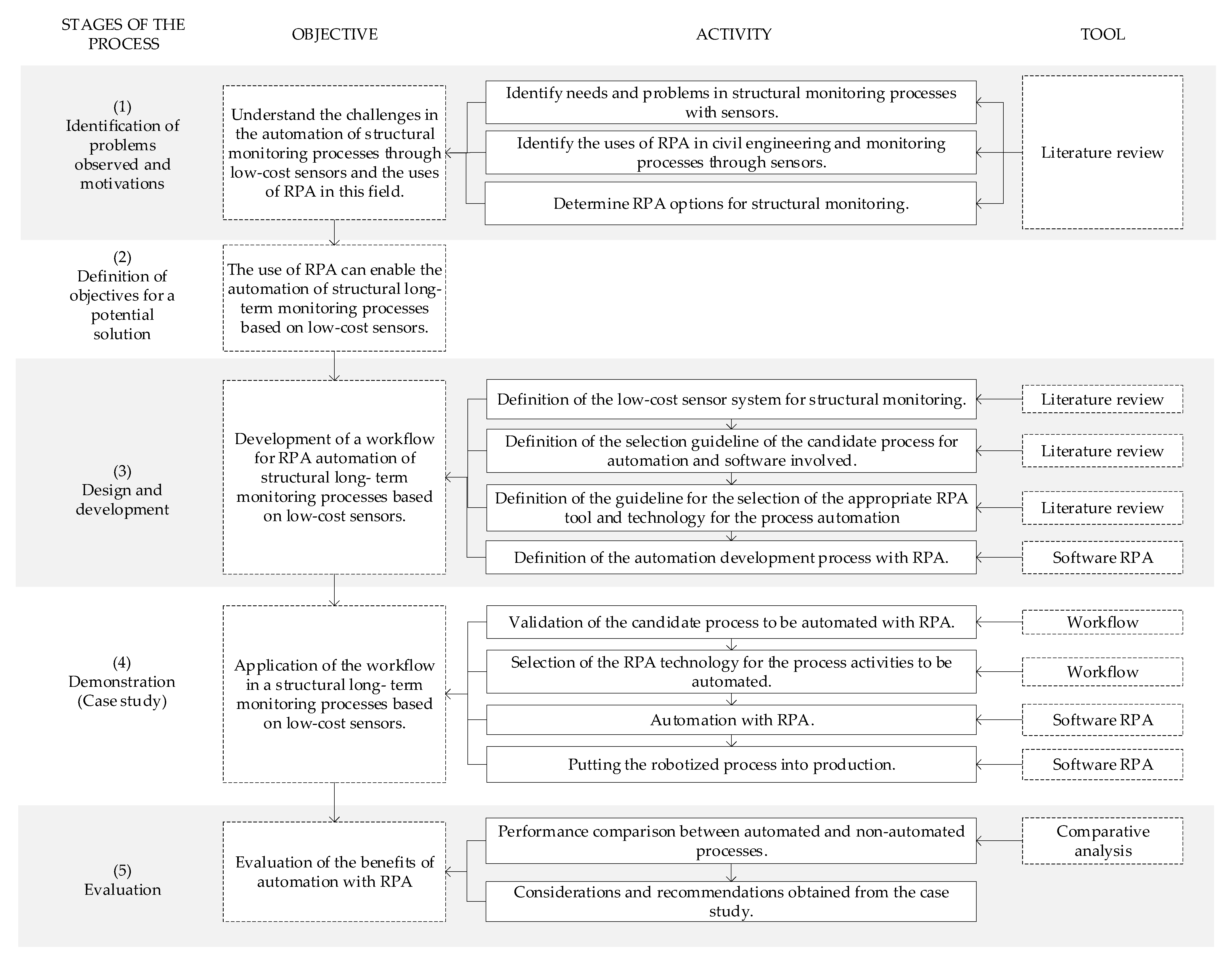
2. Research Methodology

The research methodology for this article was based on Design Sciences (Design Science Research Method–DSRM) [60,61]. This is a suitable method for engineering science and solving real-world problems through artefacts, and the output of DRSM is a proof solution concept [60]. This framework was adopted with reference to the applications made by [62,63,64,65] and structured in the following five stages: (1) Identification of problems observed and motivations, (2) Definition of objectives for a potential solution, (3) Design and development, (4) Demonstration (case study), and finally, (5) Evaluation. The research activities and the tools used in the different stages are summarised in Figure 1:
As shown in Figure 1, in the first stage of the methodology, a literature review was developed with the following aims:
  • Identifying problems and needs in structural monitoring processes with low-cost sensors and the manual data processing.
  • Identifying the uses of RPA in civil engineering and structural monitoring processes.
  • Determining RPA options to apply to the structural monitoring process with low-cost sensors.
Section 3 details the literature review process and the selection of works regarding low-cost sensors in the literature, as well as the differences in how the sensors sent and dealt with the generated information.
In the second stage, based on the literature review and after identifying the literature gap, the objective of a potential solution was defined as the application of RPA to automate structural long-term monitoring processes based on low-cost sensors.
In the third stage, a workflow was proposed for the automation of the structural monitoring process with RPA—the DSRM artefact—through the following four activities: (1) defining the sensor system to be automated, (2) defining how to select the candidate automation process and identifying the software involved, (3) defining how to select the RPA tool and technology for automation, and (4) developing the automation development process with RPA.
In the fourth stage, the proposed workflow was applied in an SHM process, and this step was concluded with the automated process working—the DSRM output. It was also expected that this workflow could be applicable as a straightforward task to other fields of civil engineering with repetitive processes that used feasible applications for automation with RPA.
In the fifth stage, the performance of the automation was evaluated through a controlled test in a time window. The benefits achieved by the automation of the process were also analysed. Finally, considerations and recommendations were established for future studies.

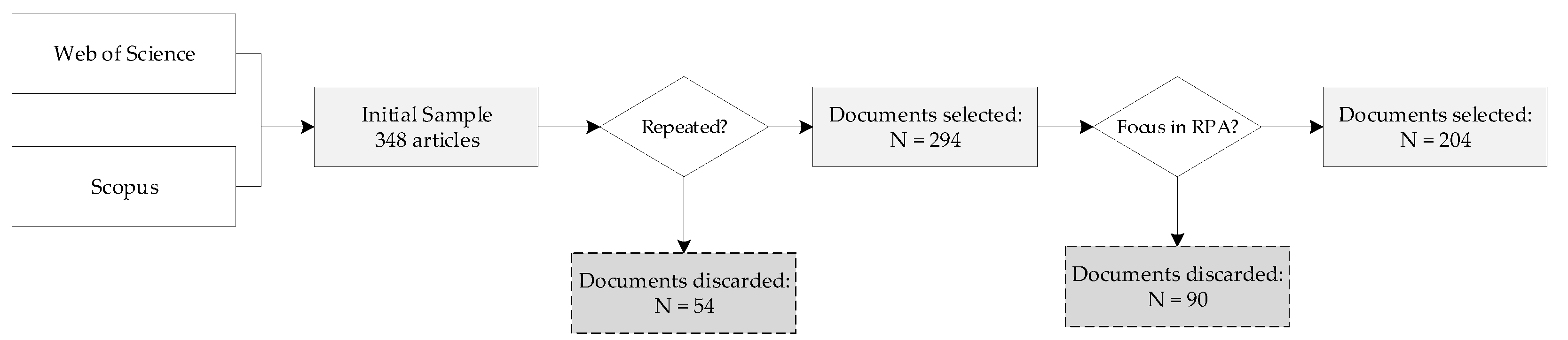
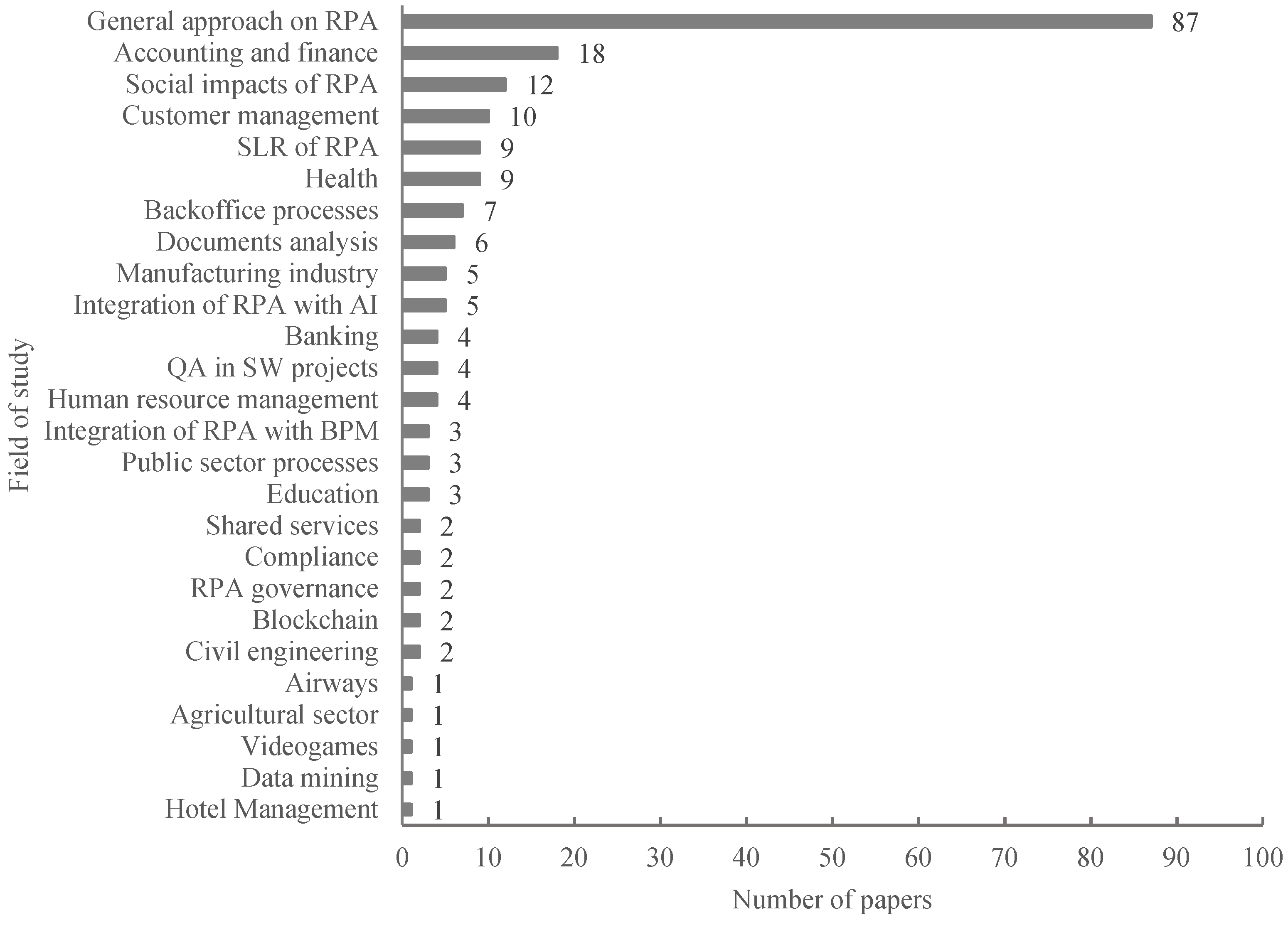
3. Literature Review

3.1. IoT in SHM

Internet of Things (IoT) refers to the protocols for linking physical objects with sensors, software, and other technologies enabling data exchange over the internet [66,67,68,69,70]. Thanks to its advantages, IoT has been widely applied to civil engineering and SHM. In fact, a number of applications have been presented in the literature in these fields. Among many others, these applications include the cultural heritage preservation, the analysis of concrete technology and crack detection, as well as material tracking in the construction process and its monitoring [59]. IoT technology was also used for real time evaluation of dynamic sensor information and to send alerts to the users if fixed thresholds were exceeded (see, e.g., [45]). A detailed review of the application of IoT in SHM was recently reviewed in [59]. Nevertheless, this work includes no reference to the use of RPA protocols. The only applications of RPA connected to IoT technology in the literature are mainly focused on the system connection together with artificial intelligence, machine learning, big data, and blockchain [49,70,71,72,73,74,75,76,77].
IoT and RPA, in general, enable interoperability between devices and applications [59,78]. However, there are differences in the type of application and the number of devices. RPA and IoT are complimentary but different technologies [58]. While RPA is being used to automate activities that involve a high volume of manual effort, IoT is being oriented towards automation and data analysis through the internet [58]. RPA, on the other hand, allows linking between different applications that require a smaller volume of interconnected applications and computers. The application of RPA to enable high levels of iterations has been widely proven in transactional banking processes [79,80].
It should be noted that RPA is not presented in this work as a replacement for IoT technology. The ability of the used low-cost accelerometer to start data acquisition by itself and upload the acquired files to a cloud makes it an IoT-based device. Actually, in this work, RPA is programmed to perform repetitive tasks to enable the control of the data acquisition process, as well as to identify and solve malfunctioning errors while the IoT-based system is working.

3.2. Robotic Process Automation

Automated processes with RPA are also known in the literature as bots or robots, and this automatization is produced with RPA software. Robots usually perform the following tasks: data transfer between applications through screen scraping, email query processing, and collation of payroll data from different sources, similar to what a human user would do [53,81]. To address an overview of RPA in the academic literature, Scopus and the Web of Science were surveyed to determine the productivity in this field. The key terms used were “robotic process automation” or “RPA”, with an initial sample of 348 articles obtained. After discarding duplicates and articles not focused on RPA or RPA applications, a sample of 204 papers was obtained. The selection process is summarised in Figure 2. This process was based on the reading of the abstracts of these papers. In specific cases, the sample paper was consulted when the abstract did not clarify the focus on RPA.
The yearly distribution of the selected articles is shown in Figure 3. As can be seen, RPA has captured increasing interest over the past four years, and 2020 was the year with the highest productivity.
The works were also classified according to their field of study. This information is summarized in Figure 4.
The analysis in Figure 4 shows that the works were focused on a general approach to an RPA field, and a holistic perspective of this technology was applied. Aspects highlighted in this group of works were contextualization in industry 4.0 [82] and trends in its application [83,84] The accounting and finance field included applications such as the automation of typical and repetitive accounting tasks [54], the auditing process [85,86], and case studies [50,87]. The third most developed field was the study of the social impacts of RPA. These papers mainly addressed aspects such as the change to human work with the task substitutions made with RPA [88], RPA–human coexistence [89], and psychological impacts on workers [87].
In the process automation field, technologies can be classified according to task type for automation and level of intelligence. RPA is oriented to performing a digital task and is less smart than machine learning. RPA executes only what has been programmed in a repetitive manner [90]. Considering the limitations of RPA, there are some eligibility specifications for the processes that are required to be automated. [81,91] present the process selection criteria to address efficient process automation considering the perspectives of task, data, system utilized, and human activities. The evaluation criteria include the number of activities, deviation cases, loops, number of systems involved, and users performing task in the process. According to [81], the most important eligibility criteria were the standardisation level of the selected process and their tasks. A standardised sequence of activities had to have a minimum number of exceptions, variations, or outcomes. The perspective of the system focused on the software with which the RPA interacted. The premise was to choose processes with low complexity in terms of the number of applications, sequence of screens, or interfaces. However, from the human viewpoint, processes should not require high interpretation skills, such as drawing a conclusion based on reading a text. The limitation was that the RPA technology was based on a rule-based flow and lacked learning capabilities [81]. As mentioned above, automating processes with RPA involved interactions with different computer applications. Therefore, the automation process and the effectiveness level of these interactions depended on the application architecture that the RPA was faced with. The above, for example, depended on the activity of reading a table on a web page that was developed with HTML language.
Following [92], the Gartner Magic Quadrant gave the most influential global benchmarking of information technology applications. According to the 2021 version of this report, the most prominent RPA business software programs were Uipath, Blueprism, and Automation Anywhere [93]. For these applications, the automation process was based on a series of RPA sub-technologies and mechanisms of interaction with the applications of a computer. The above accounted for different levels of capacity and stability. There were also automation options that were made to work with certain applications due to their massive use, for example, Excel and SAP Enterprise Resource Planning (ERP). These sub-technologies are summarised in the following table, adapted from [94].
As shown in Table 2, the sub-technologies have advantages and disadvantages, addressing different levels of performance for the same need. Desktop Automation is the most reliable sub-technology for automation [94].
The implementation of RPA could be carried out at different scales [95], from the automation of a specific process to the constitution of an environment of multiple robots [96] operating in a coordinated way and maintained by a Centre of Excellence (CoE) [57,91]. This aspect was relevant considering the fact that the implementation of RPA involved the transfer, in part or in whole, of a process that had been previously developed by humans and was now executed by bots. Therefore, in the event of any production environment problems, both the systems the robot interacted with and the RPA software had to maintain a certain level of performance. The above aspects were monitored by a CoE [97].
According to [98,99], the implementation of RPA must follow a certain life cycle for correct operation and the minimisation of risks. This RPA life cycle has the following stages: (1) Process discovery, consisting of studying the documentation of the process and determining whether or not it is a candidate for automation. If the process is eligible to be automated, the (2) design stage is developed, where automatable tasks and data flows are specified. (3) In the development stage, the RPA code is developed, and successive tests are performed to detect errors and ensure the expected performance. Finally, in stage (4), operation and maintenance, the automatised process for working in a productive environment is considered. In this phase, different errors (due to exceptions not detected in the previous stages) or change requirements of the RPA code are resolved.
In an enterprise context of RPA implementation, organisations are attracted to RPA because this technology promises benefits and savings [100]. However, it is not always clear how to manage (or govern) RPA over time [91]. For this reason, an institutional RPA-Governance policy is necessary [100] to capture the automation needs and execute them according to a prioritisation that considers technical feasibility as strategic alignment [101]. Establishing RPA governance allows specifying decision rights and responsibilities for important automation decisions and creates a framework to encourage desirable behaviours in the use of RPA [102].
Regarding the application of RPA in civil engineering, sensors, and monitoring, three papers were found that were published between 2020 and 2021. Then, concerning the field of study shown in Figure 4, [103] was related to the integration between RPA and Artificial Intelligence (AI) and [104] and [105] were linked to civil engineering. These articles are summarised in Table 3.
According to Table 3, in the work of Shah et al. [103], a Facial Emotion Recognition (FER) system was developed using Raspberry Pi 3 B+. RPA was used to automate the FER training process, in which a Python code linked to Raspberry Pi 3 B+ was executed with Uipath. Yamamoto et al. [104] implemented a remotely monitored building energy-saving system in which the applications that were involved were interfaced with RPA through remote control. The automation was based on image capture (Image Automation, according to Table 2) and linked to Excel, where the process rules were recorded.
Finally, a similar approach to this research can be found in the work of Shah et al. [105]. This work was a digital twin framework that was developed for temperature monitoring through sensors linked to Programmable Logic Controller (PLC) programs and open-source software. Uipath was the RPA application used to capture user input (a temperature value) and execute a Computational Fluid Dynamics (CFD) routine with this data.
In the following section, the application of the proposed workflow for the automatization of the data management of low-cost sensors is presented for the first time in the literature.

4. RPA Development Method

4.1. RPA Workflow

As presented in Section 3.2, the implementation of RPA follows a life cycle. For this research, a workflow was proposed for the application of RPA in the SHM processes. This workflow was based on the literature review and is presented in Figure 5.
The application of this workflow was intended to result in an automated process with a minimum of manual work. The proposed workflow was based on the following four stages: (I) Process discovery and RPA governance preconditions: this stage sought to evaluate the process and the preconditions of governance where automation would be installed. The candidate process was evaluated based on the guidelines proposed in Wellmann et al. [81], reviewing the level of standardisation and the correct development of the manual tasks selected for automation. Additionally, the savings of the FTEs could be calculated in this stage for the estimation of benefits. Regarding RPA governance, the existing preconditions for the organisation to adopt this technology had to be validated at this stage. These preconditions were related to (1) the previous RPA developments for reuse, and (2) the maintenance capabilities of the RPA technology, namely the role of the CoE. The above was relevant because the operation of a bot involved permanent monitoring since the stability of the robotic process would depend on the systems involved and the changes they experienced. Finally, (3) the information security requirements were studied. As an output of this first stage, the documentation of the current process (As-Is process [106]) and the identification of the preliminary improvements to the process, also named “quick wins” [107], were obtained. This documentation considered the process diagrams, procedures, screenshots, and videos of the working applications and the analysis of the FTEs.
In the second stage, (II) Process To-Be design, the automated process, called the To-Be process [106], was designed based on the background obtained in the previous stage. This stage began with the analysis of the process documentation, governance, and performance requirements. This analysis was conducted to determine the feasibility of selecting the RPA sub-technology for automatization development. Finally, the process was reformulated, which could involve modifying, adding, or deleting existing tasks. The premise was to define an optimised sequence of activities to be automated, not necessarily the process in its initial pure state.
The third stage, (III) RPA Deployment and testing, consisted of constructing the robot according to the designed process with RPA software. The above was a process of development and successive tests that validated that each task (e.g., a click, reading text, writing text) worked correctly and according to the defined sequence. These tests were performed in a test environment as well as in production environments.
The fourth and final stage, (IV) Operation and maintenance, considered the robots operating in a productive environment according to the designed process developed in stage II. At this stage, the CoE had a leading role and had to take care of the correct functioning of the robots through monitoring. This control was usually carried out with control panels using logs obtained from the automatised process. If errors were detected, changes in the bot workflow would be carried out by the CoE, guaranteeing operational continuity.
In the following section, the application of the proposed workflow is explained for an SHM process case.

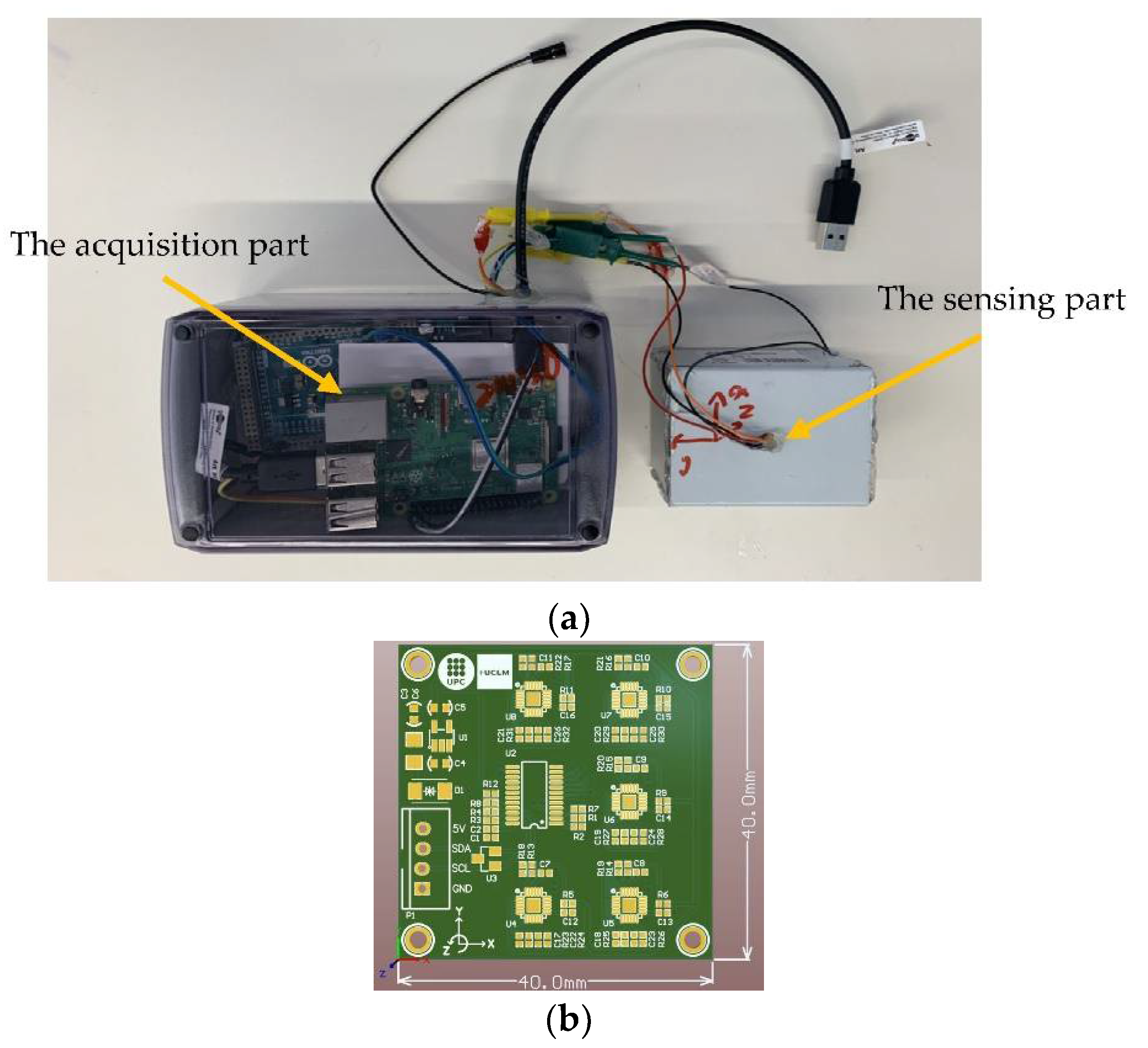
4.2. Representation of the Needed Steps for Data Acquisition Process of a SARA

In this section, first, the reason behind choosing a SARA for this research is outlined. Then, a brief introduction to the sensing part and the data acquisition part of a SARA is presented. Finally, the necessary steps for successfully performing a data acquisition experiment with a SARA are explained.
As it is already presented in Table 1, a SARA is a low-cost accelerometer with many positive aspects such as internet connection, high accuracy, and post-synchronisation capability. A SARA stands out from most of the current low-cost accelerometers in the literature, and the accuracy and the resolution of a SARA can also be compared with those of some piezoelectric accelerometers. Table 4 compares a SARA’s RMS resolution and price with some commercial accelerometers that are widely used in SHM applications intended for bridges and footbridges.
It should be noted that a SARA is the only wireless solution presented in Table 4. Additionally, it is essential to mention that a SARA does not require extra Data Acquisition Equipment (DAQ). However, to acquire data from every single channel of the piezoelectric accelerometers (Numbers 2 and 3), 700 € was needed on average [18].
It is essential to mention that SARA is a low-cost accelerometer that offers post-synchronization capability, has a noise density of 0.00005 m/s2 and is already validated in a field test on a footbridge. Additionally, to validate the robustness and accuracy of SARA, one of them is calibrated in the Applus company [43]. These qualifications make SARA a suitable choice for using cutting-edge technologies such as RPA.
A SARA is a triaxial accelerometer that has improved noise density and accuracy due to the combination of the outputs of five synchronised MPU9250 circuits by using a multiplexor (TCA9548A). It is detailed in [18,43] that reporting the averaged results of five similar low-cost accelerometers aligned and located on a rigid plate has a better RMS resolution, noise density, and accuracy. In addition, a SARA automatically downloads and relocates the latest microcontroller and acquisition code from the cloud to its hard drive. Later, every hour, the SARA uploads its acquired data to a cloud. This way, the hard drive will never become overwhelmed or filled.
The SARA sensor used for this research is shown in Figure 6a, with two essential parts: (1) Sensing part: this part contained the aligned accelerometers and the multiplexor, and (2) Acquisition part: this part contained the Arduino that was responsible for converting the outputs of the accelerometers to a typical acceleration value (g) and the Raspberry Pi 3+ that was used to save the outputs of the Arduino and give internet access to the whole system. Raspberry Pi is a low-cost Linux-based computer. Raspberry Pi worked as the system’s brain and controlled all the processes. The compact version of the SARA circuit developed by the research group is presented in Figure 6b. The performance of this sensor has been validated in laboratory conditions by the Applus company, and for the modal analysis of real structures (such as the Polvorines Footbridge in Barcelona, Spain) [43] with a noise density as low as 0.00005 m/s2.
It should be noted that the information for each SARA corresponded to the averaged measurement of acceleration at a particular location, and this information had to be analysed independently from the information obtained by the other SARAs. Therefore, every SARA had to be individually checked and scheduled for an acquisition process. It should also be clearly stated that this process was manual and required a large amount of work. In addition, this was an unfeasible procedure for the long-term monitoring of a large number of sensors in the monitoring of real structures.
Furthermore, it is essential to point out that SARA uses both Arduino and Raspberry Pi for a robust data acquisition and enabling the post-synchronization of several accelerometers. Arduino works as a data conditioner and Raspberry Pi works as a low-cost data acquisition system that can give wireless access to the data acquisition process and the low-cost accelerometer configuration with microsecond resolution [43]. It is important to highlight that the proposed methodology is not limited to Arduino-based sensors. In fact, its adaptation to other IoT-based sensor solutions (such as ESP32 and ESP8266 based microcontrollers) is a straightforward task.
To start a data acquisition for a single SARA, the Raspberry Pi first had to be reached virtually through the internet. This could be done through the Virtual Network Computing (VNC) software, a remote-control program. With every VNC account, up to five Raspberry Pis could be wirelessly controlled in the free plan. Every Raspberry Pi with a Raspbian operating system had the VNC server software preinstalled. To reach every SARA, a series of steps had to be taken. The required steps are illustrated in Figure 7.
Figure 7 shows the logging panel of the VNC software where the credentials of the account (steps 1 and 2) had to be typed. Figure 7b shows the main window of the virtual software. In step 3, the computer team had to be selected. Figure 7c shows the available sensors of the team where the name of the targeted sensor had to be chosen. Figure 7d shows the necessary credentials of the selected sensor. For higher security, the username and password of each sensor had to be introduced each time a user logged in.
The steps summarised in Figure 7 enabled the user to enter the acquisition environment of a single SARA. However, the VNC platform on the free plan had a team member limitation of five. Therefore, with more than five SARAs, more than one VNC account would be needed. Even though the SARA would download the latest microcontroller and acquisition code to its hard drive from a cloud, it would require help to execute them correctly. Raspberry Pi could be programmed to run both of these codes, but unfortunately, no notice or alarm would be shown in the case of a problem or misbehaviour. After the user entered the desired SARA, the last updated Arduino (Figure 8) code had to be uploaded to the SARA microcontroller. The Arduino code controlled the sensing part and converted the output of the accelerometer into conventional units (g or m/s2). Then, after successfully uploading the newest Arduino code, the Python code for the data acquisition was run. This code was used to obtain the data from the Arduino, add a timestamp with microsecond resolution, and save the data on a file on the Raspberry Pi hard drive. It can be seen from the way the SARA worked that a simple data acquisition procedure required a large amount of effort. Furthermore, during the data acquisition, a few additional problems could appear. For example, in the initiation process of data acquisition, there was always a chance of the sensors malfunctioning. If the ground connection of the sensing part of a SARA was not correctly connected to the ground, an error with a magnitude of −0.06 and a sampling frequency of 1 Hz appeared. From then on, the sensor did not measure any vibrations and did not save the coding error. The only way to solve this problem was to restart the microcontroller by disconnecting it from the power source. To solve this issue, the Raspberry Pi had to be rebooted. In this way, for a short period, the Arduino was discharged. However, to make long-term monitoring energy efficient, data acquisition is not generally permanent [32]. In this case, active personnel would be needed to supervise or to perform the steps as mentioned above for every single attempt of the data acquisition.
The required processes in SARA could be done:
(1) Manually: It was evident that for scheduled data acquisitions, somebody needed to be online for programming, controlling, and rebooting all the sensors in the case of an initiation error. This methodology was verified in a series of site tests. However, these procedures would require a large amount of time and attention. Human errors (such as forgetting about an accelerometer, uploading the wrong file, or not checking all the sensors periodically) could affect the whole data acquisition program. Moreover, repeating the whole data acquisition was necessary because the captured data were not useful.
(2) Automatic processes with Python and Linux: The Raspberry Pi could be scheduled to start up, connect to the internet, mount a shared drive, and bring the latest microcontroller and the Python acquisition codes to the folders of interest. However, through experiments, it was seen that the Raspberry Pi could not correctly upload to the Arduino through the already installed Arduino platform in all its attempts. In addition, in the case of an error with the sensing part or the Arduino microcontroller, the system would become stuck in a loop of rebooting with no way out. Using and learning Python and Linux codes to automatise a SARA was time-consuming, very difficult for implementing changes, challenging to implement in real applications, not user friendly, and required specialised and advanced knowledge of the core coding of Raspberry Pi.
RPA was presented as an alternative to automating SHM with a SARA. RPA was capable of performing actions on different applications. All these actions were orchestrated using a process flow that directed the course of activities based on the information displayed in the applications. Therefore, RPA could make decisions by “reading” what was displayed on the screen. This process flow was executed through visual programming, which made the use of RPA simple and flexible.
Next, we present the robotisation of this SHM with RPA, with the application of the proposed workflow.

5. Case Study: Use of RPA to Control Information from SHM Obtained with a SARA

The following section describes how the RPA workflow was applied to the SHM process to analyse the information from the SHM of the low-cost monitoring system SARA.

5.1. Process Discovery and RPA Governance Preconditions

A summary of the SHM process involved in the SARA development is presented in Figure 8.
Figure 8 corresponds to the (As-Is) process described in the previous section. This figure includes the following five activities: (1) Open the remote control using the VNC viewer. (2) Select the Arduino sensor and run, in order to open the Raspberry Pi microcomputer and run an Arduino code. (3) Run the data acquisition program in the Python code. (4) Check the results of the data acquisition in the sensor’s folder. The sensor data files were generated approximately every ten minutes, with a size of 9 Mb. If the process failed, only one file was generated that slowly increased in size for hours or days without reaching the size of 9 Mb. If the data files were not generated, an error would be considered and activity (5) would be performed, which was the resetting of all applications. If there was no error, the process paused for a period of waiting time, and then rechecking in the form of a loop was performed.
For process automation, Uipath RPA software was used. According to the Gartner Magic Quadrant [66], this application was chosen with consideration of its good reputation and the availability of all its functionalities in unlimited trial mode, which facilitated academic work. For RPA technologies applicable in the process, process activities 1, 2, and 3 had to be performed in a mode using Image Automation through the VNC application. For this case, the robot had to identify the different buttons of the sequence of screens through images.
For the governance preconditions, the owners of the SHM process were researchers from a university who had not used RPA before. Considering the experimental context of the SHM process, there were no information security requirements to consider. It was sufficient to keep the robot operational on a physical computer with access to VNC.

5.2. Process To-Be Design

This section describes how the To-Be process was analysed and redesigned. It was verified that there were difficulties in the RPA automation of activity 4, as described in Figure 8, which were related to error detection. When the data file size grew “slowly” when loading in the sensor’s folder, this error was found. However, the reading of the size of the file had to be performed continuously by reading an image in a file name. The above procedure required a high level of programming effort and knowledge of exceptions. After several tests using Image Automation for activity 4, it was impossible to obtain a stable performance. To resolve this problem, activity 4 of the As-Is process was modified. The SARA was reprogrammed to export a readable file with the name “error” in the sensor’s folder when an error occurred. Then, it was programmed in Python that all the contents of that folder be shared every hour through Google Drive. This shared folder was visible from any computer and was left accessible where Uipath was installed. This solution enabled a more stable performance, reducing time consumption. The second kind of error was verified when the sensor in the directory had generated no data file.
The As-Is process had only two paths, to remain in an error check loop or to reboot the process. Therefore, in the case of any exception that arose throughout the process, the reboot had to be performed. However, if the error persisted, reboot instances could be limited, and a message could be sent to users via email.
Figure 9 shows the redesigned process that was automatised using Uipath in all activities.
Considering the lack of RPA capabilities in the organisation, it was determined that the role of CoE would be assumed collaboratively between two research groups. The UPC (Catalunya Polytechnic University) in Barcelona had physical access to the sensors. The PUCV (Pontifical Catholic University of Valparaíso) was responsible for maintaining the sensors via access to the sensors through the VNC, the shared folder, and the RPA application available on a computer.

5.3. RPA Deployment and Testing

With the definitions from the previous stage, an RPA code was built in Uipath software using Image Automation and Desktop Automation technologies. Figure 10 shows the process implemented in Uipath. The figure also indicates the correspondence between the RPA sub-activities and the activities displayed in the general diagram of Figure 9.
As shown in Figure 10, in activity 1, an open action for the VNC application with the access credentials preinstalled was considered, and activity 1 was kept in the foreground of the screen where the following interactions were made. In activity 2, entering a folder where the executable file for Arduino was located was considered, and the folder was given a “double click.” If the Arduino run was not completed successfully, an error control was implemented to restart the task. This control checked the “error” or “completed” message on the Arduino control screen. Since the deployment time of the different screens could have a delay, this was controlled by incorporating a forced delay between the screens. The values for these delays were between 5 s and 20 s, which were the times identified after the tests to ensure the correct refreshing of the application screens.
In activity 3, a folder where the Python executable file was located was entered using “double click”. The robot then opened Python and executed the code with the sending of the F5 key. After this task, the software was programmed to wait for one hour to continue with activity 5.a. This last activity was controlled through the IF statement, verifying the existence of the “error” file thrown by the Python program or the non-existence of files generated in the directory. If the correct file was found, the process was working properly, and the software waited for another hour. Otherwise, the robot notified the users of the email error, with a built-in Uipath “send email” activity and predefined access credentials, as shown in Figure 11a. Finally, the robot performed the reboot directly in the Raspberry Pi command panel Figure 11b. The robot stopped its operation when the number of errors had been repeated in succession up to n times (n parametric value). The robot sent a notification message by email (activity 5.b).

5.4. Operation and Maintenance

At this stage, the robot was put into production and monitored by the CoE. During this monitoring, minimal errors were detected for the deployment times of the screens, which could have an origin in the internet connectivity. These bugs were corrected by performing adjustments, adding longer timeouts to the Uipath delay actions, and connecting the computer to a VNC account from the UPC university.
The sensor was installed in a column in the Civil Engineering Department of Campus Nord of UPC university Barcelona, Spain. This experiment aimed to check the performance of the RPA tool itself, not the modal analysis of the building under study. The acceleration was recorded along three axes (x, y, z), as shown in Figure 12.
The robot was submitted to a final test for 48 h, with the correct behaviour obtained as defined in the process. This test started on 15 October (day 1) at 17:24 h and finished on day 3 at 17:30. In this test, two errors were forced to evaluate the robot’s behaviour: Error 1 at 13:24 on October 17th and Error 2 at 16:40 on day 3. Figure 13 shows the acceleration records obtained from SARA during the 48 h testing for the three axes (x, y, z). Figure 13 shows the two error events, which generated record discontinuities of 15 and 18 min.
For both errors, notification by email was received according to the defined process, as shown in Figure 14.
The data capture process over 48 h generated 234 files with an average of 9.35 Mb each, every 12 min on average. Figure 15 shows the cumulative volume of data generated, which reached a total of 2200 Mb at the end of the test. Therefore, the hourly volume of data generated was 46 Mb. It should be noted that the acquired data is stored in a hard disk and shared via Google Drive to visualise the RPA process. The generated data are encrypted and stored on a computer (or a virtual machine) [43]. What is sent via email is a notification to users when the RPA detects errors, but no files are sent by this means.
The automated process also saved man-hours. As shown in Table 5, a person spent 5 min every hour reviewing the process. Over 48 h, the person would have worked four man-hours. However, this effort was even greater when it was considered that the human resources would be involved in the process continually, even if the personnel only spent a few minutes on each review. This saving of human effort was one of the most appreciated advantages of RPA.
According to Table 5, applying the RPA allowed a saving of 95.8% of the required man-hours in the SHM process. In economic terms, and considering the cost of a project engineer in Chile—where the CoE is located—the man-hour has a cost of €15 [108]. On the other hand, the annual cost of a Uipath RPA license amounts to 3000 € per year [94]. Considering that the bot can operate 24/7, the hourly cost of this virtual workforce reaches 0.342 €, that is, only 2.28% of the cost of an engineer. This estimated saving is aligned with the findings of other research where the impact of RPA on the reduction of FTEs is revealed. [84,91,100].
It should also be clearly stated that this work focuses on controlling, managing the functional ability, and checking the good programming of a low-cost accelerometer (SARA). With some programming modifications, this system can be applied to other low-cost sensor configurations (no need for Arduino + Raspberry Pi).

6. Discussion

As a proof of concept (POC), this research has developed the application of RPA to automate an SHM process for the first time in the literature. Through this POC, the aim of the RPA technology proposed in this paper is to automate the management of the SHM of a structure. This POC allows the evaluation of the interoperability between RPA technology and low-cost sensor applications inside the SHM process, achieving a functional result. The above is allowed by a simple programming language based on a flowchart and a high-level language that does not require advanced programming skills. RPA developments in other industries take a few weeks [109]. In addition, a limitation of this research is the study of multiple sensor systems. Nevertheless, this technology is used on a daily basis for managing large operations (such as automatic reviews of bank accounts, see, e.g., [79]). Several virtual computers are programmed to work together to handle large amounts of information efficiently in these applications. These works give the precedents for considering that the proposed RPA methodology could be used to handle a different number of sensors efficiently together.
Therefore, future studies could develop the simultaneous execution of several SHM processes in a multi-robot environment. Although the individual automation of each of these processes can be achieved by applying the proposed workflow, an environment of many robots in operation requires orchestration that could be supported by a new robot (a robot that monitors other robots) and the monitoring that corresponds to the CoE. Furthermore, a new study could address the review of acceleration files in real-time and check the files for critical values to alert users using the bot when this occurs. Since robots do not sleep or ask for vacations, they will be continually available. It should be noted that the aim of RPA applications in this future work will not be to control thousands of sensors simultaneously but to monitor the performance of the sensors included in real SHM systems. The number of sensors will obviously depend on the structural characteristics as well as the monitoring budget.
In this paper, RPA was used for short-term monitoring of low-cost sensors, although the aim is to continue this research to prove its strong performance in long-term monitoring. This work has not been carried out yet, but the research will be addressed soon. It is important to highlight this paper’s aim: to illustrate the benefits and potential of using RPA in civil engineering applications to encourage researchers to use it.

7. Conclusions

The Robotic Process Automation (RPA) knowledge base in the literature focuses on a generic approach to technology, followed by the automation of more transactional processes such as accounting, finance, customer management, and back-office, among others. In addition, RPA is a relatively new field of study for which the first articles date from 2016.
This paper is an applied type of research, in which the functional ability of a low-cost accelerometer is managed and controlled. This case study is developed for the first time in civil engineering. In addition, this paper proposes an RPA implementation workflow. This workflow is elaborated on generically to make it replicable for other work and to encourage researchers, civil engineering professionals, and the maker community to venture into this technology area.
The low-cost accelerometer employed in this paper (SARA) uses an Arduino as its signal conditioner and a Raspberry Pi as its data acquisition equipment. Although they have the advantage of being low-cost, these devices have limited functionality, and data capture becomes problematic when they have variable performance. After applying the automation workflow with RPA, it was possible to automate the control, management, and auto fault detection of SARA for a long-term data acquisition process. One of the benefits of this automation is that the data capture process of the device is kept operational, despite the instabilities that might occur. The activities described in the workflow have the aim of challenging the initial process (As-Is) to obtain an improved and optimal version for optimization (To-Be). The workflow led to testing to detect and solve the process variabilities that affected the performance aspects, such as the effect of the connection speed on the scrolling of the screens of the applications mounted on Raspberry Pi.
The control, management, and automatic problem solving of the sensors require a high number of man-hours. RPA allows for the saving of this effort by offering a greater capacity for continuous monitoring. One of the main advantages of RPA is its simple programming.
Future studies could develop the simultaneous execution of several processes in a multi-robot environment. Although the individual automation of each of these processes can be achieved by applying the proposed workflow, an environment of many robots in operation requires orchestration that could be supported by a new robot (a robot that monitors other robots) and the monitoring that corresponds to the CoE. Furthermore, a new study could address the review of acceleration files in real-time and check the files for critical values to alert users of the bot when this occurs. Since robots do not sleep or ask for vacations, they will be continually available.

Author Contributions

This article represents the results of teamwork. E.A. designed the research methodology and developed the literature review. S.K. developed the SARA process. E.A., S.K. and M.A. developed the automation with RPA. E.A., S.K. and J.A.L.-G. reviewed and edited the article. All authors have read and agreed to the published version of the manuscript.

Funding

The Spanish Ministry of Economy and Competitiveness: BIA2017-86811-C2-1-R; The Spanish Ministry of Economy and Competitiveness: BIA2017-86811-C2-2-R; The Secretaria d’ Universitats i Recerca de la Generalitat de Catalunya, Catalunya, Spain: 2017 SGR 1482; Spanish Agencia Estatal de Investigación del Ministerio de Ciencia Innovación y Universidades grant and the Fondo Social Europeo grant: PRE2018-083238.

Institutional Review Board Statement

Not applicable.

Informed Consent Statement

Not applicable.

Data Availability Statement

Not applicable.

Acknowledgments

The authors wish to thank all of the experts who participated in this study. The authors also wish to thank the TIMS space (Technology, Innovation, Management, and Innovation) of the School of Civil Engineering of the Pontificia Universidad Católica de Valparaíso (Chile) and the Universidad de Castilla-La Mancha, where part of the research was carried out. The authors are indebted to the Spanish Ministry of Economy and Competitiveness for the funding provided through the research project BIA2017-86811-C2-1-R, and BIA2017-86811-C2-2-R. All these projects are funded with FEDER funds. It is also to be noted that funding for this research has been provided for Seyedmilad Komarizadehasl by the Spanish Agencia Estatal de Investigación del Ministerio de Ciencia Innovación y Universidades grant and the Fondo Social Europeo grant (PRE2018-083238).

Conflicts of Interest

The authors declare that they have no conflict of interest.

References

  1. Proske, D. Fatalities due to bridge collapse. In Proceedings of the Institution of Civil Engineers—Bridge Engineering; Thomas Telford Ltd.: London, UK, 2020; Volume 173, pp. 1–24. [Google Scholar]
  2. Won, J.; Park, J.-W.; Park, J.; Shin, J.; Park, M. Development of a Reference-Free Indirect Bridge Displacement Sensing System. Sensors 2021, 21, 5647. [Google Scholar] [CrossRef] [PubMed]
  3. Rizzo, P.; Enshaeian, A. Challenges in Bridge Health Monitoring: A Review. Sensors 2021, 21, 4336. [Google Scholar] [CrossRef] [PubMed]
  4. Ha, D.W.; Park, H.S.; Choi, S.W.; Kim, Y. A Wireless MEMS-Based Inclinometer Sensor Node for Structural Health Monitoring. Sensors 2013, 13, 16090–16104. [Google Scholar] [CrossRef] [PubMed] [Green Version]
  5. Mobaraki, B.; Lozano-Galant, F.; Soriano, R.P.; Pascual, F.J.C. Application of Low-Cost Sensors for Building Monitoring: A Systematic Literature Review. Buildings 2021, 11, 336. [Google Scholar] [CrossRef]
  6. Farré-Checa, J.; Komarizadehasl, S.; Ma, H.; Lozano-Galant, J.; Turmo, J. Direct simulation of the tensioning process of cable-stayed bridge cantilever construction, Automation in Construction. Autom. Constr. 2022, 137, 104197. [Google Scholar] [CrossRef]
  7. Kang, J.-S.; Chung, K.; Hong, E.J. Multimedia knowledge-based bridge health monitoring using digital twin. Multimed. Tools Appl. 2021, 80, 34609–34624. [Google Scholar] [CrossRef]
  8. Huang, Y.; Wang, Y.; Fu, J.; Liu, A.; Gao, W. Measurement of the real-time deflection of cable-stayed bridge based on cable tension variations. Meas. J. Int. Meas. Confederat. 2018, 119, 218–228. [Google Scholar] [CrossRef]
  9. Komarizadehasl, S.; Khanmohammadi, M. Novel plastic hinge modification factors for damaged RC shear walls with bending performance. Adv. Concr. Constr. 2021, 12, 355–365. [Google Scholar] [CrossRef]
  10. Komarizadehasl, S.; Mobaraki, B.; Lozano-galant, J.A. A Comprehensive Description of a Low-Cost Wireless Dynamic Real-Time Data Acquisition and Monitoring System. In Proceedings of the 15th Edition of the International Conference on Durability of Building Materials and Components, (DBMC 2020), Barcelona, Catalonia, 20–23 October 2020; pp. 1–6. [Google Scholar]
  11. Sun, L.; Shang, Z.; Xia, Y.; Bhowmick, S.; Nagarajaiah, S. Review of Bridge Structural Health Monitoring Aided by Big Data and Artificial Intelligence: From Condition Assessment to Damage Detection. J. Struct. Eng 2020, 146, 04020073–04020095. [Google Scholar] [CrossRef]
  12. Muttillo, M.; Stornelli, V.; Alaggio, R.; Paolucci, R. Structural Health Monitoring: An IoT Sensor System. Sensors 2020, 20, 4908. [Google Scholar] [CrossRef]
  13. Aloisio, A.; Di Battista, L.; Alaggio, R.; Fragiacomo, M. Sensitivity analysis of subspace-based damage indicators under changes in ambient excitation covariance, severity and location of damage. Eng. Struct. 2020, 208, 11023. [Google Scholar] [CrossRef]
  14. Peng, T.; Nogal, M.; Casas, J.R.; Lozano-Galant, J.A.; Turmo, J. Constrained observability techniques for structural system identification using modal analysis. J. Sound Vib. 2020, 479, 115368–115384. [Google Scholar] [CrossRef]
  15. Peng, T.; Nogal, M.; Casas, J.R.; Turmo, J. Planning low-error SHM strategy by constrained observability method. Autom. Constr. 2021, 127, 103707. [Google Scholar] [CrossRef]
  16. Feng, D.; Feng, M.Q. Model Updating of Railway Bridge Using in Situ Dynamic Displacement Measurement under Trainloads. J. Bridge Eng. 2015, 20, 04015019–04015031. [Google Scholar] [CrossRef]
  17. Guo, T.; Frangopol, D.M.; Chen, Y. Fatigue reliability assessment of steel bridge details integrating weigh-in-motion data and probabilistic finite element analysis. Comput. Struct. 2012, 112–113, 245–257. [Google Scholar] [CrossRef]
  18. Komarizadehasl, S.; Mobaraki, B.; Ma, H.; Lozano-Galant, J.-A.; Turmo, J. Development of a Low-Cost System for the Accurate Measurement of Structural Vibrations. Sensors 2021, 21, 6191. [Google Scholar] [CrossRef]
  19. Komarizadehasl, S.; Mobaraki, B.; Ma, H.; Lozano-Galant, J.-A.; Turmo, J. Low-Cost Sensors Accuracy Study and Enhancement Strategy. Appl. Sci. 2022, 12, 3186. [Google Scholar] [CrossRef]
  20. Lei, J.; Nogal, M.; Lozano-Galant, J.A.; Xu, D.; Turmo, J. Constrained observability method in static structural system identification. Struct. Control. Health Monit. 2018, 25, e2040. [Google Scholar] [CrossRef]
  21. Tomàs, D.; Lozano-Galant, J.A.; Ramos, G.; Turmo, J. Structural system identification of thin web bridges by observability techniques considering shear deformation. Thin-Walled Struct. 2018, 123, 282–293. [Google Scholar] [CrossRef] [Green Version]
  22. Bhowmik, B.; Tripura, T.; Hazra, B.; Pakrashi, V. Robust linear and nonlinear structural damage detection using recursive canonical correlation analysis. Mech. Syst. Signal Process. 2020, 136, 106499. [Google Scholar] [CrossRef]
  23. Giordano, P.; Quqa, S.; Limongelli, M. Statistical Approach for Vibration-Based Damage Localization in Civil Infrastructures Using Smart Sensor Networks. Infrastructures 2021, 6, 22. [Google Scholar] [CrossRef]
  24. Bhowmik, B.; Tripura, T.; Hazra, B.; Pakrashi, V. Real time structural modal identification using recursive canonical correlation analysis and application towards online structural damage detection. J. Sound Vib. 2020, 468, 115101. [Google Scholar] [CrossRef]
  25. Straub, D.; Chatzi, E.; Bismut, E.; Courage, W.; Döhler, M.; Faber, M.H.; Köhler, J.; Lombaert, G.; Omenzetter, P.; Pozzi, M.; et al. Value of information: A roadmap to quantifying the benefit of structural health monitoring. In Proceedings of the 12th International Conference on Structural Safety & Reliability, Vienna, Austria, 6–10 August 2017; pp. 3018–3029. Available online: https://hal.inria.fr/hal-01577257 (accessed on 23 February 2020).
  26. Panda, S.; Tripura, T.; Hazra, B. First-Order Error-Adapted Eigen Perturbation for Real-Time Modal Identification of Vibrating Structures. J. Vib. Acoust. 2021, 143, 051001. [Google Scholar] [CrossRef]
  27. Bhowmik, B.; Panda, S.; Hazra, B.; Pakrashi, V. Feedback-driven error-corrected single-sensor analytics for real-time condition monitoring. Int. J. Mech. Sci. 2022, 214, 106898. [Google Scholar] [CrossRef]
  28. Sekuła, K.; Kołakowski, P. Piezo-based weigh-in-motion system for the railway transport. Struct. Control. Health Monit. 2012, 19, 199–215. [Google Scholar] [CrossRef]
  29. Pathak, B.; Kumar, P.; Sharma, A.; Kumar, R. Earthquake Detector Using Arduino Uno. 2019. Available online: http://122.252.232.85:8080/jspui/handle/123456789/22911 (accessed on 27 December 2019).
  30. Ali, A.S.; Zanzinger, Z.; DeBose, D.; Stephens, B. Open Source Building Science Sensors (OSBSS): A low-cost Arduino-based platform for long-term indoor environmental data collection. Build. Environ. 2016, 100, 114–126. [Google Scholar] [CrossRef] [Green Version]
  31. Ozdagli, A.I.; Liu, B.; Moreu, F. Low-cost, efficient wireless intelligent sensors (LEWIS) measuring real-time reference-free dynamic displacements. Mech. Syst. Signal Process. 2018, 107, 343–356. [Google Scholar] [CrossRef]
  32. Meng, Q.; Zhu, S. Developing iot sensing system for construction-induced vibration monitoring and impact assessment. Sensors 2020, 20, 6120. [Google Scholar] [CrossRef]
  33. Grimmelsman, K.A.; Zolghadri, N. Experimental evaluation of low-cost accelerometers for dynamic characterization of bridges. In Conference Proceedings of the Society for Experimental Mechanics Series; Springer: New York, NY, USA, 2020; pp. 145–152. [Google Scholar] [CrossRef]
  34. Komarizadehasl, S.; Mobaraki, B.; Lozano-Galant, J.A.; Turmo, J. Evaluation of low-cost angular measuring sensors. In Proceedings of the International Conference of Recent Trends in Geotechnical and Geo-Environmental Engineering and Education, Brisbane, Australia, 10–11 September 2020; RTCEE/RTGEE. 2020; pp. 17–21. Available online: https://upcommons.upc.edu/handle/2117/328769 (accessed on 20 September 2020).
  35. Analog Devices, ADXL 335 Data-Sheet, (n.d.). Available online: https://www.sparkfun.com/datasheets/Components/SMD/adxl335.pdf (accessed on 1 August 2020).
  36. PCB Piezotronics, 393A03 Data-Sheet. 2008. Available online: https://www.pcb.com/contentstore/docs/PCB_Corporate/Vibration/Products/Manuals/393A03.pdf (accessed on 1 August 2020).
  37. PCB Piezotronics Model 3711D1FA20G DC Accelerometer Installation and Operating Manual. Available online: https://www.pcbpiezotronics.fr/wp-content/uploads/3741E122G.pdf (accessed on 19 April 2022).
  38. Girolami, A.; Zonzini, F.; De Marchi, L.; Brunelli, D.; Benini, L. Modal Analysis of Structures with Low-cost Embedded Systems. In Proceedings of the International Symposium on Circuits and Systems, Florence, Italy, 27–30 May 2018; pp. 1–4. [Google Scholar] [CrossRef]
  39. ST, LIS344ALH Data-Sheet. 2008. Available online: https://www.st.com/resource/en/datasheet/lis344alh.pdf (accessed on 1 August 2020).
  40. InvenSense, MPU6050 Data-Sheet. 2013. Available online: https://www.invensense.com/wp-content/uploads/2015/02/MPU-6000-Datasheet1.pdf%0A (accessed on 1 August 2020).
  41. Aguero, M.; Ozdagli, A.; Moreu, F. Measuring reference-free total displacements of piles and columns using low-cost, battery-powered, efficientwireless intelligent sensors (LEWIS2). Sensors 2019, 19, 1549. [Google Scholar] [CrossRef] [Green Version]
  42. Huerta, R.C.; Moreu, F.; Galant, J.L. Aerial Tramway Sustainable Monitoring with an Outdoor Low-Cost Efficient Wireless Intelligent Sensor. Sustainability 2021, 13, 6340. [Google Scholar] [CrossRef]
  43. Komarizadehasl, S.; Lozano, F.; Lozano-Galant, J.-A.; Ramos, G.; Turmo, J. Low-Cost Wireless Structural Health Monitoring of Bridges. Sensors 2022, 22, 5725. [Google Scholar] [CrossRef]
  44. Elhattab, A.; Uddin, N.; Obrien, E. OBrien, Extraction of Bridge Fundamental Frequencies Utilizing a Smartphone MEMS Accelerometer. Sensors 2019, 19, 3143. [Google Scholar] [CrossRef] [PubMed] [Green Version]
  45. Testoni, N.; Aguzzi, C.; Arditi, V.; Zonzini, F.; De Marchi, L.; Marzani, A.; Cinotti, T.S. A Sensor Network with Embedded Data Processing and Data-to-Cloud Capabilities for Vibration-Based Real-Time SHM. J. Sens. 2018, 2018, 2107679. [Google Scholar] [CrossRef]
  46. Magdaleno, A.; Villacorta, J.J.; Del-Val, L.; Izquierdo, A.; Lorenzana, A. Measurement of Acceleration Response Functions with Scalable Low-Cost Devices. An Application to the Experimental Modal Analysis. Sensors 2021, 21, 6637. [Google Scholar] [CrossRef]
  47. Guzman-Acevedo, G.M.; Vazquez, E.; Millan-Almaraz, J.R.; Rodriguez-Lozoya, H.E.; Reyes-Salazar, A.; Gaxiola-Camacho, J.R.; Félix, C.A.M. GPS, Accelerometer, and Smartphone Fused Smart Sensor for SHM on Real-Scale Bridges. Adv. Civ. Eng. 2019, 2019, 6429430. [Google Scholar] [CrossRef]
  48. Makoond, N.; Pelà, L.; Molins, C.; Roca, P.; Alarcón, D. Automated data analysis for static structural health monitoring of masonry heritage structures. Struct. Control. Health Monit. 2020, 27, e2581. [Google Scholar] [CrossRef]
  49. Micle, D.; Deiac, F.; Olar, A.; Drența, R.; Florean, C.; Coman, I.; Arion, F. Research on innovative business plan. Smart cattle farming using artificial intelligent robotic process automation. Agriculture 2021, 11, 430. [Google Scholar] [CrossRef]
  50. Asatiani, A.; Penttinen, E. Turning robotic process automation into commercial success—Case OpusCapita. J. Inf. Technol. Teach. Cases 2016, 6, 67–74. [Google Scholar] [CrossRef]
  51. IEEE. IEEE Guide for Terms and Concepts in Intelligent Process Automation; IEEE Corporate Advisory Group: Piscataway, NJ, USA, 2017. [Google Scholar]
  52. Van Chuong, L.; Hung, P.D.; Diep, V.T. Robotic Process Automation and Opportunities for Vietnamese Market. In Proceedings of the 2019 7th International Conference on Computer and Communications Management, Bangkok, Thailand, 27–29 July 2019; Association for Computing Machinery: New York, NY, USA, 2019; pp. 86–90. [Google Scholar] [CrossRef]
  53. Syed, R.; Suriadi, S.; Adams, M.; Bandara, W.; Leemans, S.J.; Ouyang, C.; ter Hofstede, A.H.; van de Weerd, I.; Wynn, M.T.; Reijers, H.A. Robotic Process Automation: Contemporary themes and challenges. Comput. Ind. 2020, 115, 103162. [Google Scholar] [CrossRef]
  54. Kokina, J.; Gilleran, R.; Blanchette, S.; Stoddard, D. Accountant as digital innovator: Roles and competencies in the age of automation. Account. Horiz. 2021, 35, 153–184. [Google Scholar] [CrossRef]
  55. Madakam, S. The Future Digital Work Force: Robotic Process Automation (Rpa). J. Inf. Syst. Technol.Manag.—Jistem USP 2019, 53, 1689–1699. [Google Scholar] [CrossRef]
  56. Geyer-klingeberg, J.; Nakladal, J.; Baldauf, F.; Veit, F. Process Mining and Robotic Process Automation: A Perfect Match Process Mining as Enabler for RPA Implementation. In Proceedings of the 16th International Conference on Business Process, Management 2018, Industry Track Session, Sydney, Australia, 10 September 2018. [Google Scholar]
  57. Blue Prism Software Robots. The Art of Possibility. Available online: https://www.blueprism.com/uploads/resources/white-papers/Blue-Prism-Product-Overview-Enterprise-Edition.pdf (accessed on 19 April 2022).
  58. Karn, S.; Kotecha, R. RPA-based Implementation of IoT. In Proceedings of the 4th International Conference on Advances in Science & Technology (ICAST2021), Mumbai, India, 9 May 2021. [Google Scholar] [CrossRef]
  59. Mishra, M.; Lourenço, P.B.; Ramana, G.V. Structural health monitoring of civil engineering structures by using the internet of things: A review. J. Build. Eng. 2022, 48, 103954. [Google Scholar] [CrossRef]
  60. Van Aken, J.E.; Romme, G.L. A Design Science Approach to Evidence-Based Management; Oxford University Press: Oxford, UK, 2012; pp. 140–184. [Google Scholar]
  61. Peffers, K.; Tuunanen, T.; Rothenberger, M.A.; Chatterjee, S. A Design Science Research Methodology for Information Systems Research A Design Science Research Methodology for Information Systems Research. J. Manag. Inf. Syst. 2007, 24, 45–77. [Google Scholar] [CrossRef]
  62. Romero-Chambi, E.; Villarroel-Quezada, S.; Atencio, E.; Rivera, F.M.-L. Analysis of Optimal Flight Parameters of Unmanned Aerial Vehicles (UAVs) for Detecting Potholes in Pavements. Appl. Sci. 2020, 10, 4157. [Google Scholar] [CrossRef]
  63. Prosser-Contreras, M.; Atencio, E.; La Rivera, F.M.; Herrera, R.F. Use of unmanned aerial vehicles (Uavs) and photogrammetry to obtain the international roughness index (iri) on roads. Appl. Sci. 2020, 10, 8788. [Google Scholar] [CrossRef]
  64. Jacob-Loyola, N.; Rivera, F.M.-L.; Herrera, R.; Atencio, E. Unmanned aerial vehicles (Uavs) for physical progress monitoring of construction. Sensors 2021, 21, 4227. [Google Scholar] [CrossRef] [PubMed]
  65. Díaz, G.; Herrera, R.F.; Rivera, F.M.-L.; Atencio, E. Generative design for dimensioning of retaining walls. Mathematics 2021, 9, 1918. [Google Scholar] [CrossRef]
  66. Lee, J.-L.; Tyan, Y.-Y.; Wen, M.-H.; Wu, Y.-W. Development of an ioT-based bridge safety monitoring system. In Proceedings of the 2017 IEEE International Conference on Applied System Innovation: Applied System Innovation for Modern Technology, Sapporo, Japan, 13–17 May 2017; pp. 84–86. [Google Scholar] [CrossRef]
  67. Raposo, D.; Rodrigues, A.; Sinche, S.; Silva, J.S.; Boavida, F. Industrial IoT monitoring: Technologies and architecture proposal. Sensors 2018, 18, 3568. [Google Scholar] [CrossRef] [PubMed] [Green Version]
  68. Varma, A.; Prabhakar, S.; Jayavel, K. Gas Leakage Detection and Smart Alerting and prediction using IoT. In Proceedings of the 2017 2nd International Conference on Computing and Communications Technologies (ICCCT), Chennai, India, 23–24 February 2017; pp. 327–333. [Google Scholar] [CrossRef]
  69. Kanawaday, A.; Sane, A. Machine learning for predictive maintenance of industrial machines using IoT sensor data. In Proceedings of the IEEE International Conference on Software Engineering and Service Sciences (ICSESS), Beijing, China, 24–26 November 2017; pp. 87–90. [Google Scholar] [CrossRef]
  70. Nagajayanthi, B. Decades of Internet of Things Towards Twenty-first Century: A Research-Based Introspective. Wirel. Pers. Commun. 2021, 123, 3661–3697. [Google Scholar] [CrossRef]
  71. Huo, J.; Lee, C.K. Intelligent workload balance control of the assembly process considering condition-based maintenance. Adv. Eng. Inform. 2021, 49, 101341. [Google Scholar] [CrossRef]
  72. Chmielarz, G. Present state and future application of smart technologies in manufacturing processes. Prod. Eng. Arch. 2019, 24, 14–19. [Google Scholar] [CrossRef] [Green Version]
  73. Santor, E. The Impact of Digitalization on the Economy: A Review Article on the NBER Volume Economics of Artificial Intelligence: An Agenda. Int. Product. Monit. 2020, 39, 81–90. [Google Scholar]
  74. Pillay, C.P.; Njenga, J.K. Opportunities for Reducing Expenses through Digital Innovation: The Case of an Insurance Company. Afr. J. Inf. Syst. 2021, 13, 99–112. [Google Scholar]
  75. Rane, S.B.; Narvel, Y.A.M. Leveraging the industry 4.0 technologies for improving agility of project procurement management processes. Int. J. Syst. Assur. Eng. Manag. 2021, 12, 1146–1172. [Google Scholar] [CrossRef]
  76. Finance, I. The Role of Business Leaders in Information Technology Innovation in the New Era of Disruptive Technology. Asian J. Account. Gov. 2019, 12, 133–142. [Google Scholar] [CrossRef]
  77. Kumar, V.S.; Krishnamoorthi, C. Development of electrical transduction based wearable tactile sensors for human vital signs monitor: Fundamentals, methodologies and applications. Sens. Actuators A Phys. 2021, 321, 112582. [Google Scholar] [CrossRef]
  78. Patel, M.; Shukla, A.; Porwal, R.; Kotecha, R. Customized Automated Email Response Bot using Machine Learning and Robotic Process Automation. In Proceedings of the 2nd International Conference on Advances in Science & Technology (ICAST) 2019, Mumbai, India, 8–9 April 2019; Somaiya, K.J., Ed.; Institute of Engineering & Information Technology: Mumbai, India, 2019. [Google Scholar]
  79. Wojciechowska-Filipek, S. Automation of the process of handling enquiries concerning information constituting a bank secret. Banks Bank Syst. 2019, 14, 175–186. [Google Scholar] [CrossRef]
  80. Souto, F.V.; Coello, R.P.; Olguín Barrón, F.C. COSMIC sizing of RPA software: A case study from a proof of concept implementation in a banking organization. CEUR Workshop Proc. 2020, 2725, 1–15. [Google Scholar]
  81. Wellmann, C.; Stierle, M.; Dunzer, S.; Matzner, M. A Framework to Evaluate the Viability of Robotic Process Automation for Business Process Activities. Lect. Notes Bus. Inf. Process. 2020, 393, 200–214. [Google Scholar] [CrossRef]
  82. Axmann, B.; Harmoko, H. Robotic Process Automation: An Overview and Comparison to Other Technology in Industry 4.0. In Proceedings of the 2020 10th International Conference on Advanced Computer Information Technologies (ACIT), Deggendorf, Germany, 16–18 September 2020; pp. 559–562. [Google Scholar] [CrossRef]
  83. Gupta, S.; Rani, S.; Dixit, A. Recent Trends in Automation-A study of RPA Development Tools. In Proceedings of the 2019 3rd International Conference on Recent Developments in Control, Automation and Power Engineering (RDCAPE), Noida, India, 10–11 October 2019; pp. 159–163. [Google Scholar] [CrossRef]
  84. Dey, S.; Das, A. Robotic process automation: Assessment of the technology for transformation of business processes. Int. J. Bus. Process Integr. Manag. 2019, 9, 220–230. [Google Scholar] [CrossRef]
  85. Huang, F.; Vasarhelyi, M.A. Applying robotic process automation (RPA) in auditing: A framework. Int. J. Account. Inf. Syst. 2019, 35, 100433. [Google Scholar] [CrossRef]
  86. Zhang, C. Intelligent Process Automation in Audit. J. Emerg. Technol. Account. 2019, 16, 69–88. [Google Scholar] [CrossRef]
  87. Cooper, L.A.; Holderness, D.K.; Sorensen, T.L.; Wood, D.A. Robotic process automation in public accounting. Account. Horiz. 2019, 33, 15–35. [Google Scholar] [CrossRef]
  88. Hattingh, M.; Matthee, M.; Smuts, H.; Pappas, I.; Dwivedi, Y.K.; Mäntymäki, M. Correction to: Responsible Design, Implementation and Use of Information and Communication Technology. In Conference on e-Business, e-Services and e-Society; Springer: Cham, Switzerland, 2021. [Google Scholar] [CrossRef]
  89. Oshri, I.; Plugge, A. What Do You See in Your Bot? Lessons from KAS Bank. In International Workshop on Global Sourcing of Information Technology and Business Processes; Springer: Cham, Switzerland, 2020; pp. 145–161. [Google Scholar] [CrossRef]
  90. Di-Francescomarino, C.; Dijkman, R.; Zdun, U. Business Process Management Workshops: Lecture Notes in Business Information Processing Series. In Proceedings of the BPM 2019 International Workshops, Vienna, Austria, 1–6 September 2019; Revised Selected Papers. Springer: Berlin/Heidelberg, Germany, 2019; Volume 17, pp. 523–534. [Google Scholar]
  91. Noppen, P.; Beerepoot, I.; van de Weerd, I.; Jonker, M.; Reijers, H.A. How to keep RPA maintainable? In International Conference on Business Process Management; Springer: Cham, Switzerland, 2020; pp. 453–470. [Google Scholar] [CrossRef]
  92. Snapp, S. Gartner and the Magic Quadrant: A Guide for Buyers; Vendors and Investors, SCM Focus Press: Phoenix, AZ, USA, 2013. [Google Scholar]
  93. UiPath Gartner’s Magic Quadrant RPA. Available online: https://www.uipath.com/es/company/rpa-analyst-reports/gartner-magic-quadrant-robotic-process-automation (accessed on 10 June 2021).
  94. UiPath RPA Technologies. Available online: https://www.uipath.com/es/soluciones/segun-tecnologia (accessed on 10 June 2021).
  95. Axmann, B.; Harmoko, H. The Five Dimensions of Digital Technology Assessment with the Focus on Robotic Process Automation (RPA). Teh. Glas. 2021, 15, 267–274. [Google Scholar] [CrossRef]
  96. Hwang, M.-H.; Na, U.-K.; Lee, S.; Cho, B.; Kim, Y.; Lee, D.; Shin, J. MIORPA: Middleware System for open-source robotic process automation. J. Comput. Sci. Eng. 2020, 14, 19–25. [Google Scholar] [CrossRef]
  97. Anagnoste, S. Robotic Automation Process—The operating system for the digital enterprise. In Proceedings of the International Conference on Business Excellence, Bucharest, Romania, 22–23 March 2018; Volume 12, pp. 54–69. [Google Scholar] [CrossRef] [Green Version]
  98. Martins, C. Robotic Process Automation: A Lean Approach to RPA; Instituto Superior Técnico: Lisboa, Portugal, 2018. [Google Scholar]
  99. Jimenez-Ramirez, A.; Reijers, H.A.; Barba, I.; Del Valle, C. A Method to Improve the Early Stages of the Robotic Process Automation Lifecycle. In Advanced Information Systems Engineering; CAiSE 2019; Lecture Notes in Computer Science; Giorgini, P., Weber, B., Eds.; Springer: Cham, Switzerland, 2019; Volume 11483. [Google Scholar] [CrossRef]
  100. Kokina, J.; Blanchette, S. Early evidence of digital labor in accounting: Innovation with Robotic Process Automation. Int. J. Account. Inf. Syst. 2019, 35, 100431. [Google Scholar] [CrossRef]
  101. Sönmez, E.; Börekçi, D.Y. A conceptual study on RPAs as of intelligent automation. Adv. Intell. Syst. Comput. 2020, 1029, 65–72. [Google Scholar] [CrossRef]
  102. Willcocks, L.; Hindle, J.; Lacity, M. Keys to RPA Sucess—How Blue Prism Clients Are Gaining Superior Long-Term Business Value. Available online: https://www.blueprism.com/resources/white-papers/keys-to-rpa-success-how-blue-prism-clients-are-gaining-superior-long-term-business-value/ (accessed on 19 April 2022).
  103. Saxena, S.; Tripathi, S.; Tsb, S. Deep robot-human interaction with facial emotion recognition using gated recurrent units & robotic process automation. Front. Artif. Intell. Appl. 2020, 332, 115–126. [Google Scholar] [CrossRef]
  104. Shah, K.; Prabhakar, T.V.; Sarweshkumar, C.R.; Abhishek, S.V. Construction of a Digital Twin Framework using Free and Open-Source Software Programs. IEEE Int. Comput. 2021, 7801, 1–8. [Google Scholar] [CrossRef]
  105. Yamamoto, T.; Hayama, H.; Hayashi, T.; Mori, T. Automatic energy-saving operations system using robotic process automation. Energies 2020, 13, 2342. [Google Scholar] [CrossRef]
  106. Zuhaira, B.; Ahmad, N.; Saba, T.; Haseeb, J.; Malik, S.U.R.; Manzoor, U.; Balubaid, M.A.; Anjum, A. Identifying Deviations in Software Processes. IEEE Access 2017, 5, 20319–20332. [Google Scholar] [CrossRef]
  107. Bakker, S.; Haq, G.; Peet, K.; Gota, S.; Medimorec, N.; Yiu, A.; Jennings, G.; Rogers, J. Low-carbon quick wins: Integrating short-term sustainable transport options in climate policy in low-income countries. Sustainability 2019, 11, 4369. [Google Scholar] [CrossRef] [Green Version]
  108. Solution, R.H.T. Salary Guide—Robert Half Talent Solutions. Available online: https://www.roberthalf.cl/guia-salarial/details/operaciones-jefe-de-operaciones/chile (accessed on 19 April 2022).
  109. Ortiz, F.C.M.; Costa, C.J. RPA in Finance: Supporting portfolio management: Software robot in a portfolio optimization problem. In Proceedings of the Iberian Conference on Information Systems and Technologies (CISTI), Sevilla, Spain, 24–27 June 2020; pp. 24–27. [Google Scholar] [CrossRef]
Figure 1. Research methodology.
Buildings 12 01140 g001
Figure 2. Article selection process.
Buildings 12 01140 g002
Figure 3. Yearly distribution of papers published with RPA applications.
Buildings 12 01140 g003
Figure 4. Field of study of the selected papers.
Buildings 12 01140 g004
Figure 5. Proposed workflow for the automatization SHM process.
Buildings 12 01140 g005
Figure 6. An accelerometer (SARA) with its data acquisition equipment: (a) Boxing of SARA and its data acquisition equipment, and (b) compact design of the sensing part of SARA.
Buildings 12 01140 g006
Figure 7. Entering the data acquisition system of a SARA: (a) Signing in to the VNC Viewer platform, (b) Main window of the VNC Viewer, (c) Choosing the accelerometer under study, (d) entering to the data acquisition platform of the selected accelerometer.
Buildings 12 01140 g007
Figure 8. Process to automate (As−Is).
Buildings 12 01140 g008
Figure 9. Process redesign with RPA (To−Be).
Buildings 12 01140 g009
Figure 10. RPA process diagram.
Buildings 12 01140 g010
Figure 11. Tasks for error processing. (a) Email notification. (b) Rebooting process.
Buildings 12 01140 g011
Figure 12. Installed sensor and its acceleration reference system.
Buildings 12 01140 g012
Figure 13. Acceleration amplitude records from SARA.
Buildings 12 01140 g013
Figure 14. Email notifications sent by the robot. (a) Error 1. (b) Error 2.
Buildings 12 01140 g014
Figure 15. Size of files generated (cumulative).
Buildings 12 01140 g015
Table 1. Comparison of the main characteristics of low-cost monitoring systems based on Arduino technology.
ReferenceAccelerometerRange (g)Bandwidth (Hz)Noise Density (µg/√Hz)PriceSynchronizationInternet Access
[33]ADXL335±3 g50300$530NoNo
[38]STAMP±2 g5050No dataYesYes
[31]LEWIS 1±2 g50400$73NoNo
[41]LEWIS 2±2 g250300$91NoNo
[18]CHEAP±2 g42.516284 €NoNo
[43]SARA±2 g166.551140 €YesYes
Table 2. Sub-technologies used in RPA software.
TechnologyCapacityAdvantageDisadvantage
Desktop AutomationRPA understands the user interface of the application and does not depend on the position of the screen elements for capture and consumption during the process.Reliable automation independent of screen resolution and size.Automation option not available for all cases.
Web automationScreen scraping, data extraction, data filling and interaction with elements such as buttons.Compatibility with languages such as HTML, Flash and Java.Only accessible directly with the web. Interactions via remote control (for example, VNC) do not allow integration with RPA.
Interface AutomationInteraction of RPA such as PDF, Chrome and Firefox.Recognition of controls in most Graphical User Interface (GUI) as well as OCR (Optical Character Recognition)There could be controls that RPA is not able to detect, and it is necessary to opt for a less stable technology, such as image recognition.
Screen ScrapingObtaining text from the screens of software.Compatibility with documents format, such as PDF.Automation option not available for all cases.
Image AutomationInteraction with screenshots of applications running live on a remote controller or virtual machine.Recognise items in an app’s screenshot (image).Of all the automation options, this is the least stable, since it depends on the resolution and size of the screen, as well as the relative position of the controls a user interacts with (e.g., a button).
Automation of core systemsInteraction with mainframe systems.Compatibility with T3700, terminals, Java.Automation option not available for all cases.
SAP AutomationNative interaction with SAP ERP.Compatibility with some SAP functionalities.Automation option not available for all SAP functionalities.
Excel AutomationNative interaction with ExcelExecution of Excel controls natively integrated into RPA applications. Some of these commands operate without having to open Excel.Automation option not available for all Excel functionalities.
Table 3. Related papers with civil engineering, sensors, and process monitoring.
ReferenceLocationYearField of StudyUse of RPAApplications AutomatedRPA Software UsedRPA Sub-Technology Used
Saxena et al. [103]India2020Integration of RPA with Artificial IntelligenceIntegrating software activities in Facial Emotion Recognition training process using Raspberry Pi 3PythonUipathPython activity pack with Desktop Automation
Yamamoto et al. [104]Japan2020Civil EngineeringDeveloping a building automation system (BAS) for energy savingExcelNot specifiedImage Automation
Shah et al. [105]India2021Civil EngineeringIntegrating software activities for temperature monitoring in a buildingFreeCAD Eclipse Ditto OpenFlow SimFlow ParaViewUipathImage Automation
Table 4. Comparing a SARA with habitual accelerometers for the SHM of bridges.
NoNamePriceAcceleration RangeSampling FrequencyResolutionSensitivity
gHzmgV/g
1SARA140±2.03330.920.625Triaxial
2IMI 604B31613±5050000.350.100Triaxial
3IMI 607A61324±50100000.350.100Uniaxial
Table 5. Man-hour savings during the monitoring process.
Day 1 (Cumulative Minutes)Day 2 (Cumulative Minutes)
SHM without RPA120240
SHM with RPA510
Total savings of required man-hours 230 (95.8%)
Publisher’s Note: MDPI stays neutral with regard to jurisdictional claims in published maps and institutional affiliations.

