
Study on Damping Performance of Hyperboloid Damper with SMA-Negative Stiffness

Abstract
:1. Introduction
2. SMA-Negative Stiffness Hyperboloid Shock Absorber
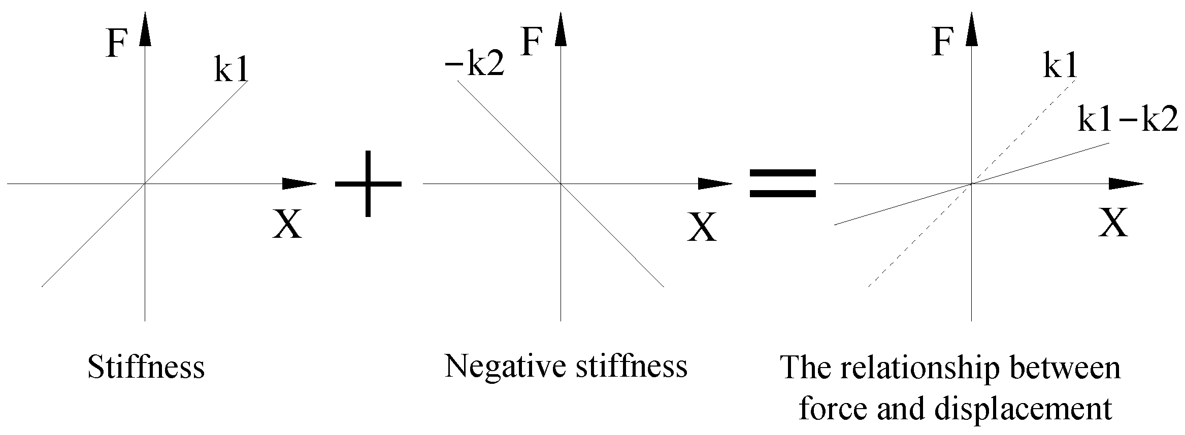
2.1. Design Principle
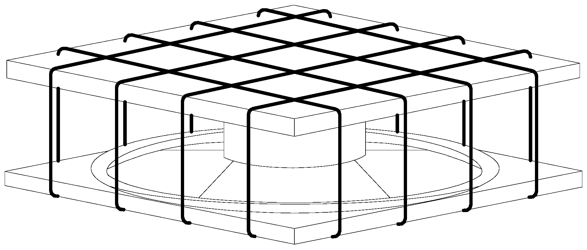
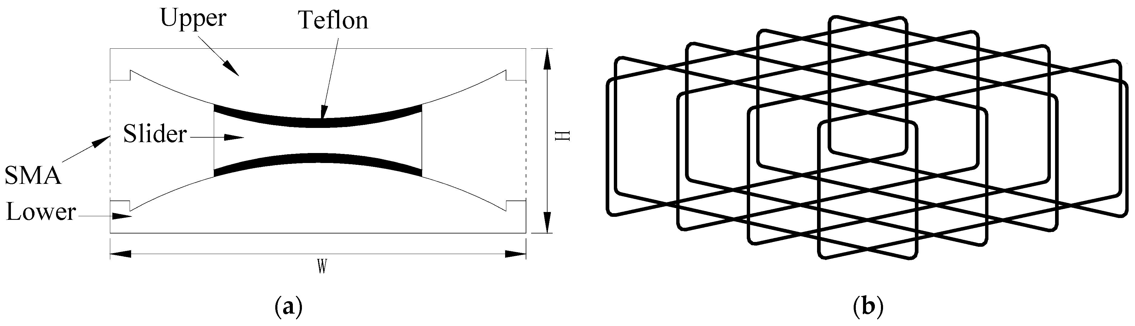
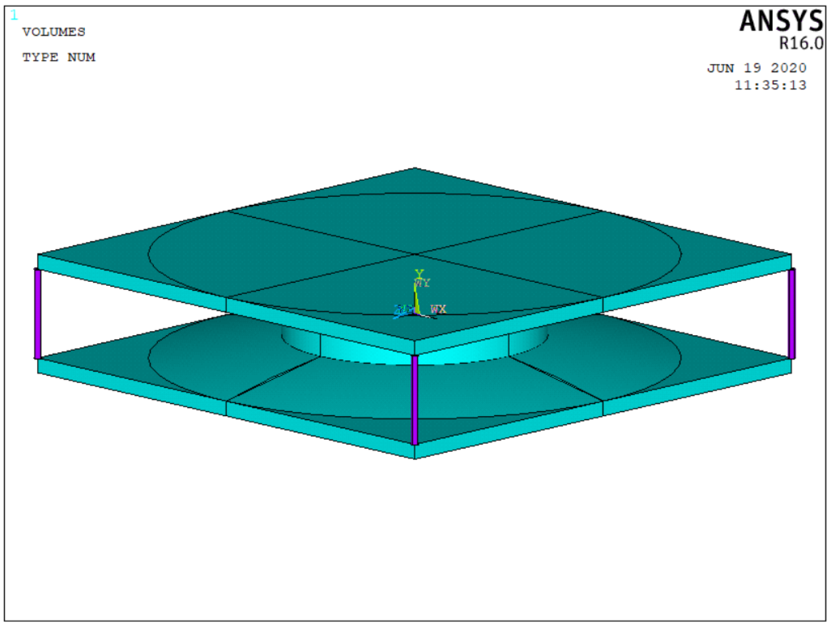
2.2. Structure
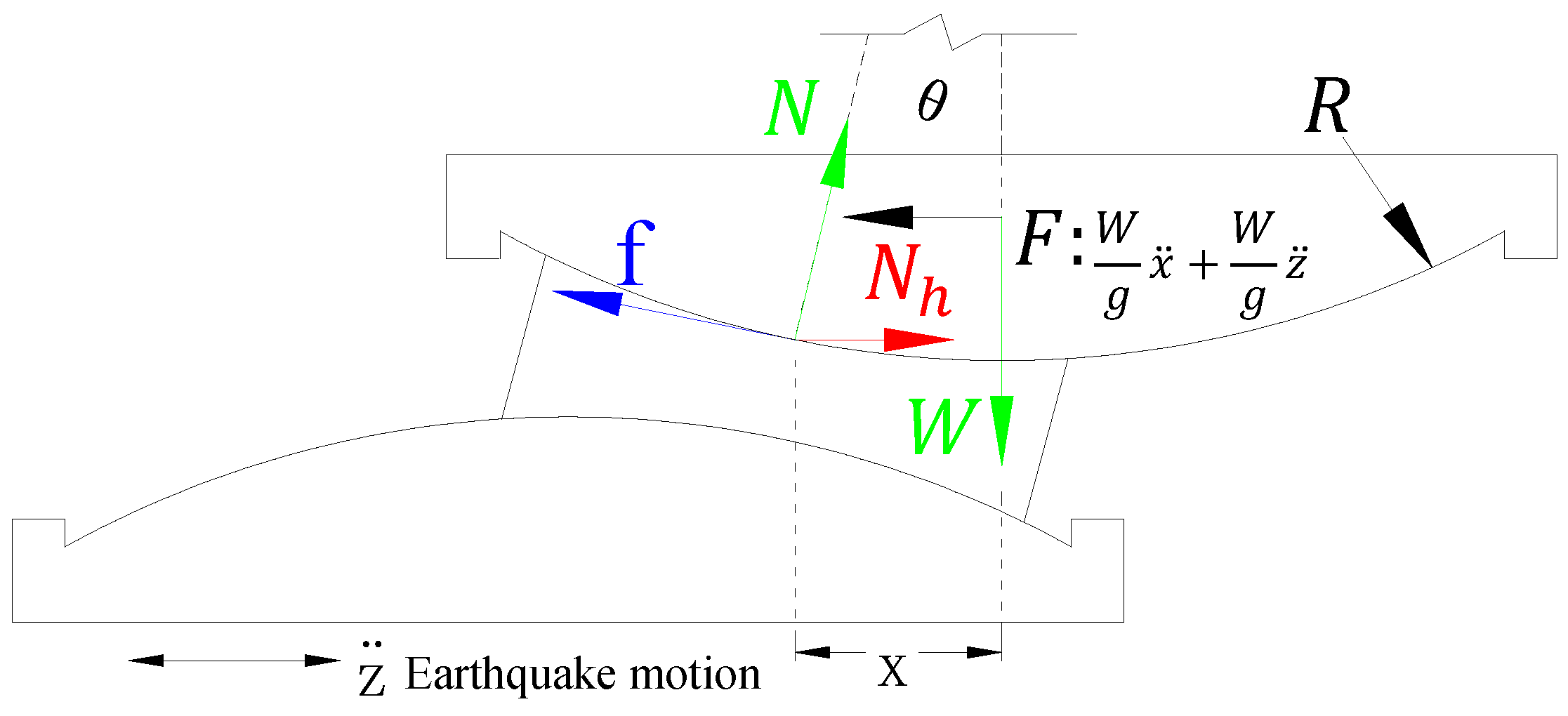
2.3. Mechanism
3. Hysteretic Performance of SMA-Negative Stiffness Hyperboloid Shock Absorber
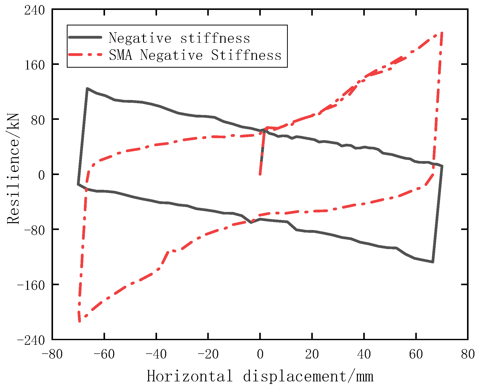
3.1. Restoring Forces and Displacements of SMA Cables and Negative Stiffness Systems
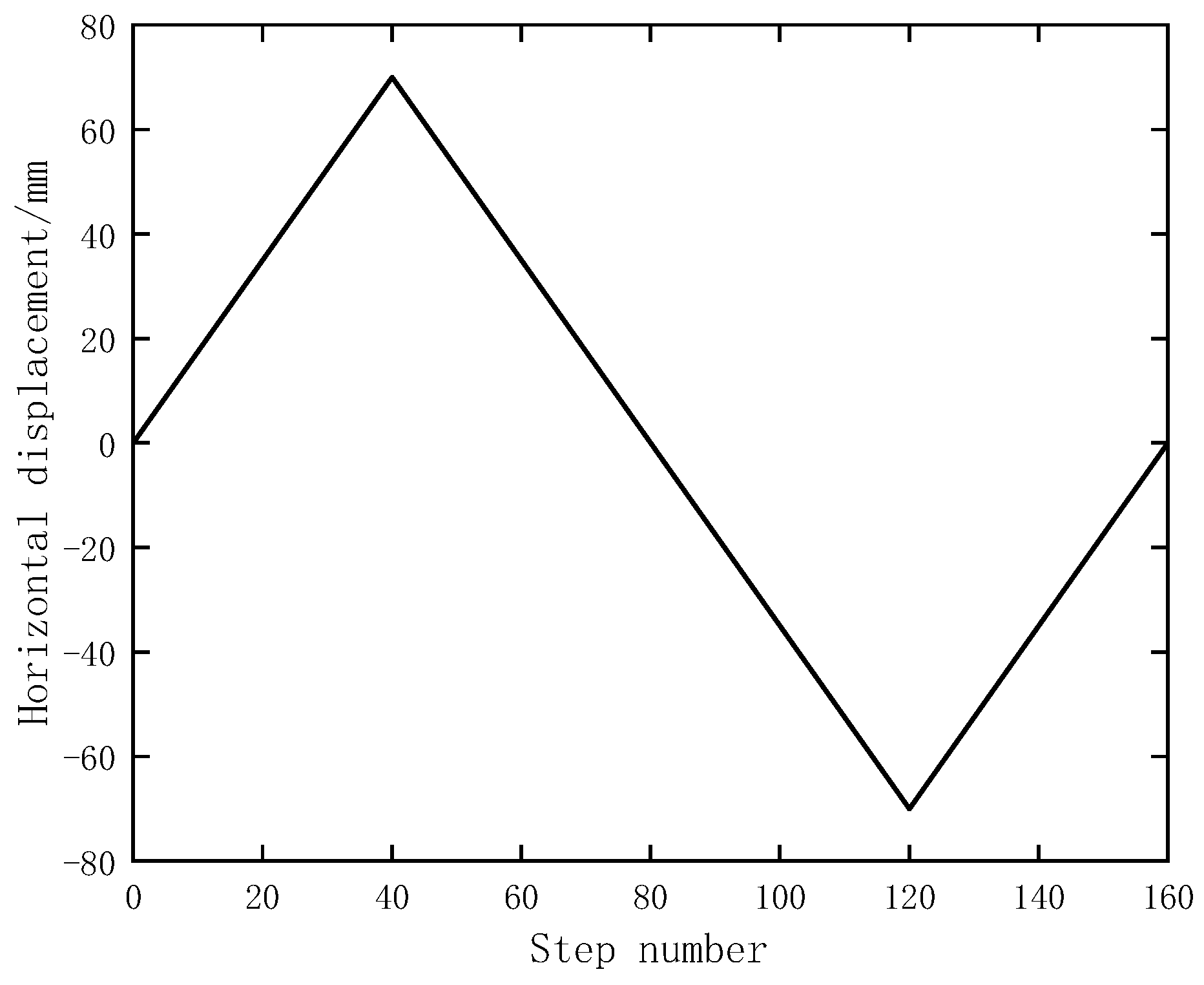
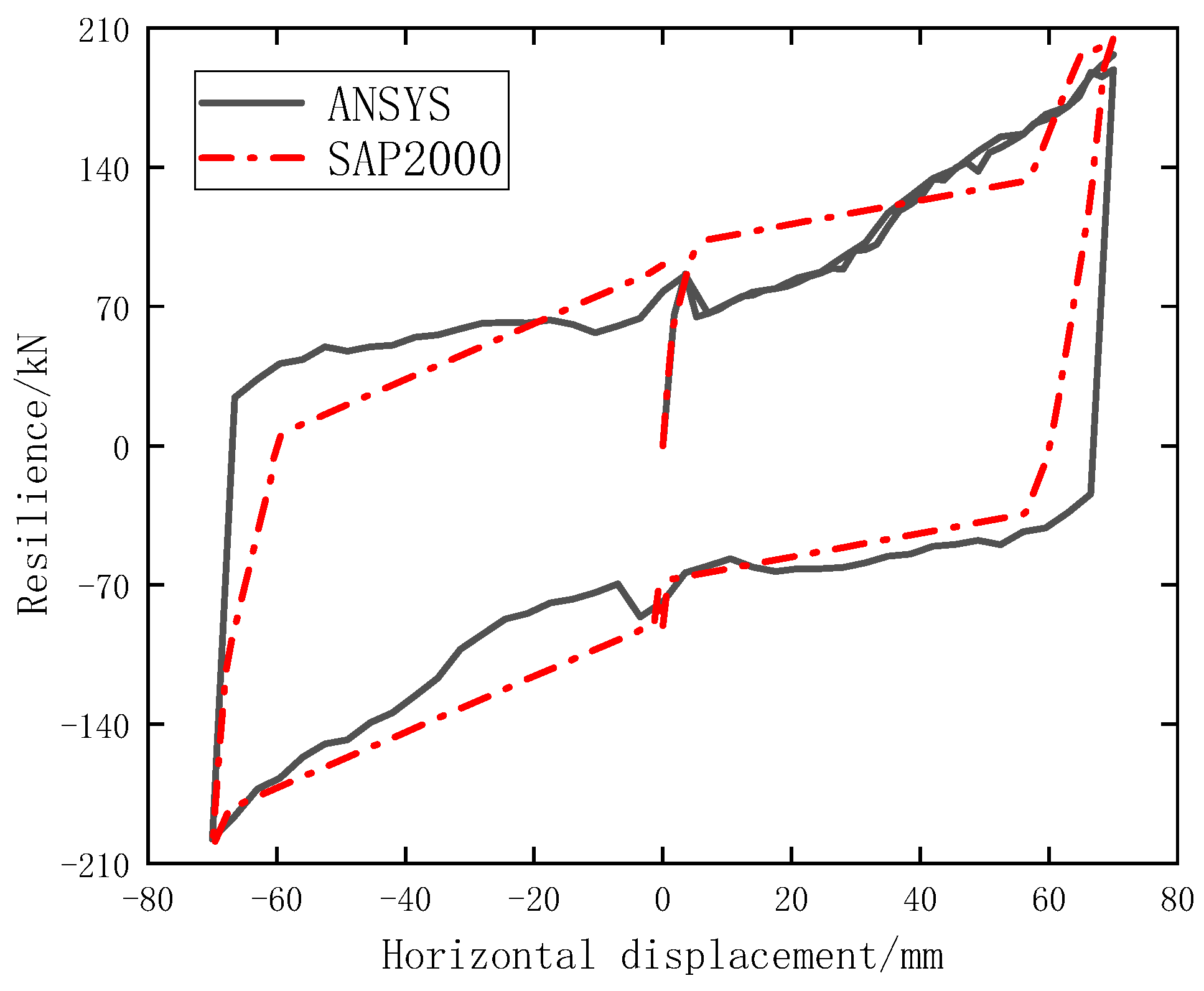
3.2. Numerical Simulation
3.3. Parametric Analysis
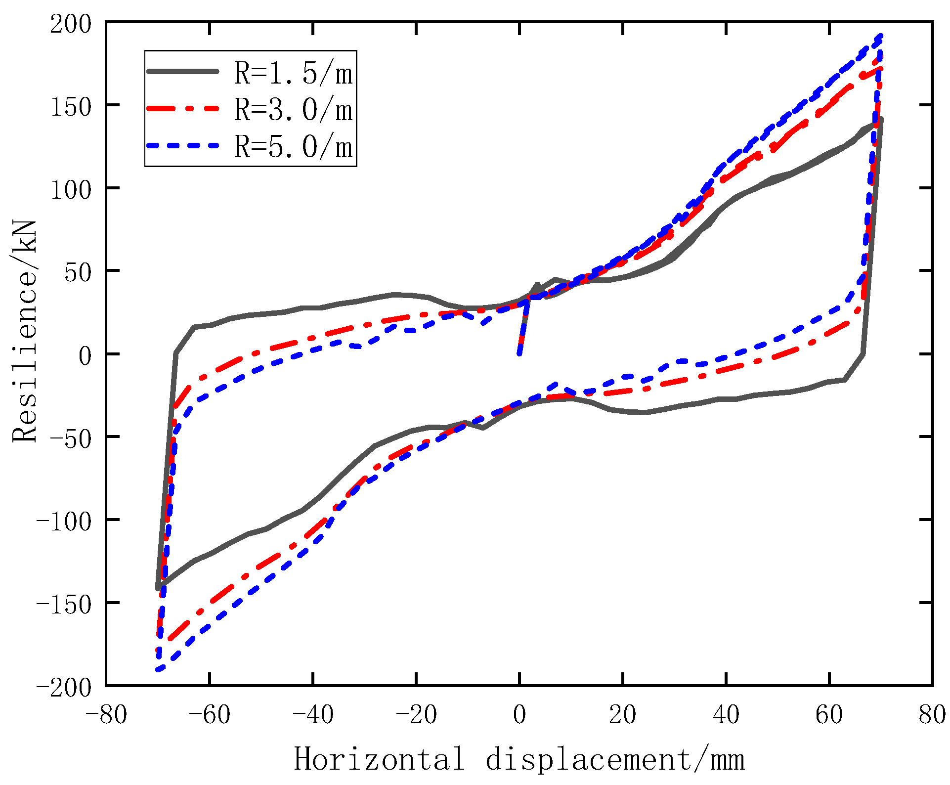
3.3.1. Variation of Mechanical Properties with Radius
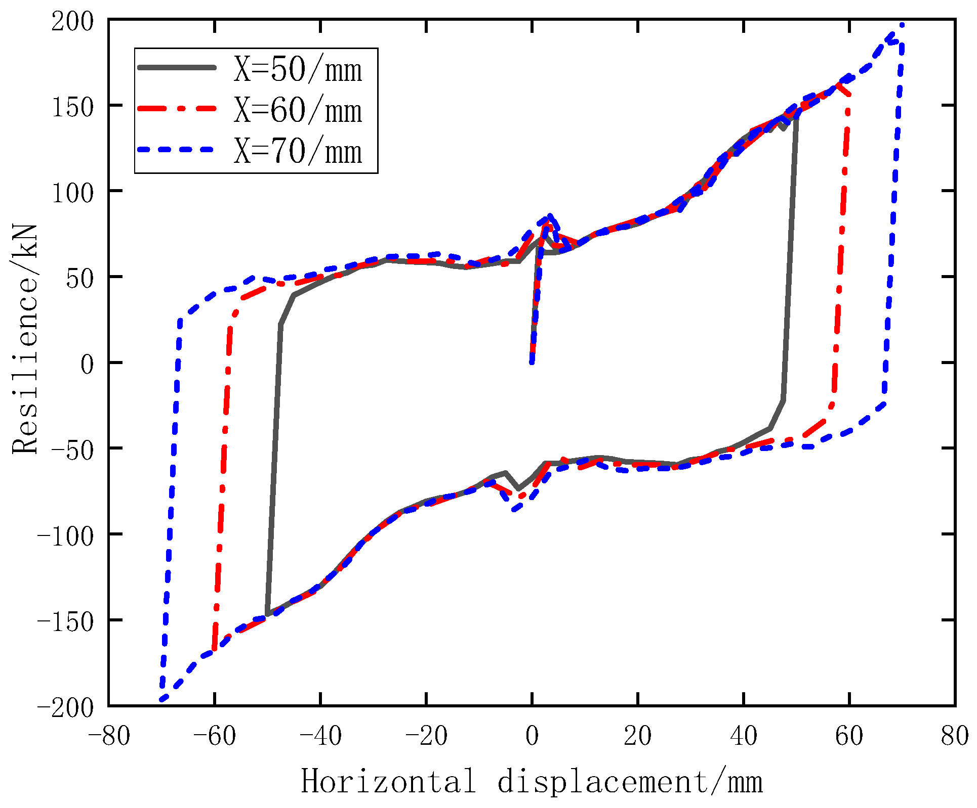
3.3.2. Variation of Mechanical Properties with Horizontal Displacement
3.3.3. Variation of Mechanical Properties with Cross-Sectional Area of SMA Cable
3.3.4. Variation of Mechanical Properties with Vertical Pressure
3.3.5. Effect of Hyperboloid Shape on Mechanical Properties
4. Shock Absorption Performance Analysis
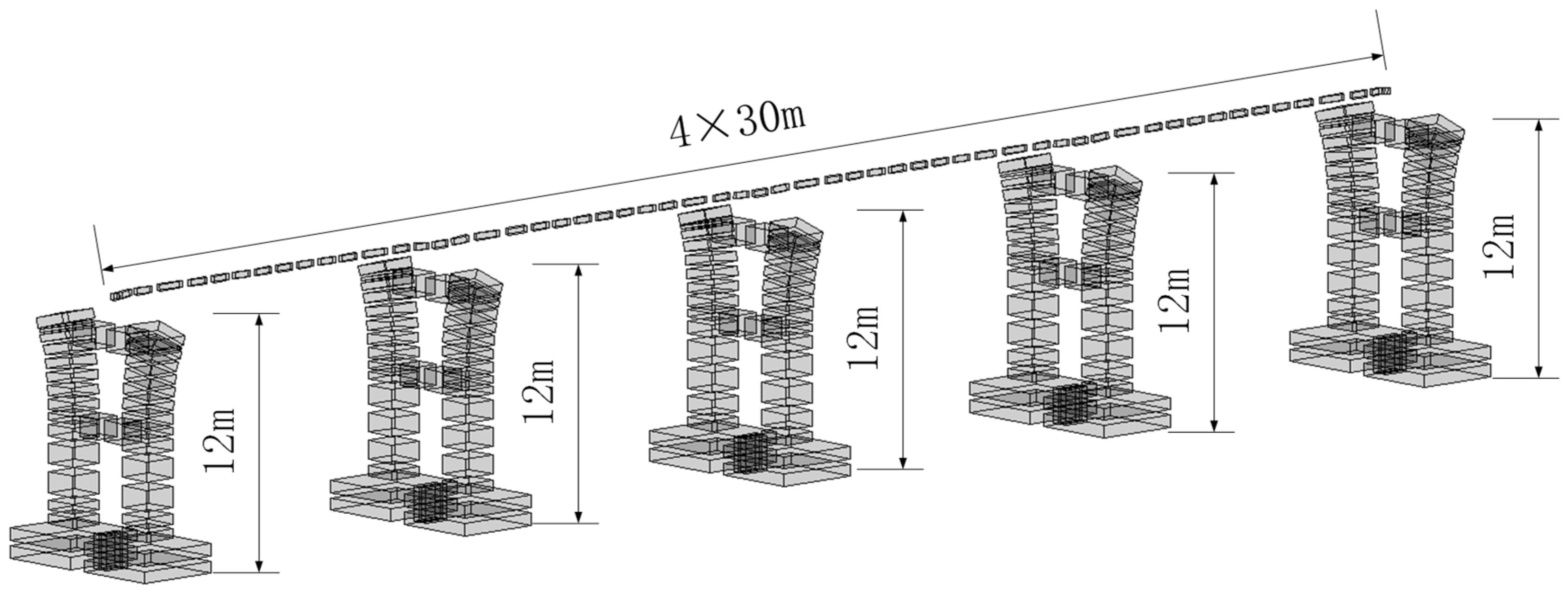
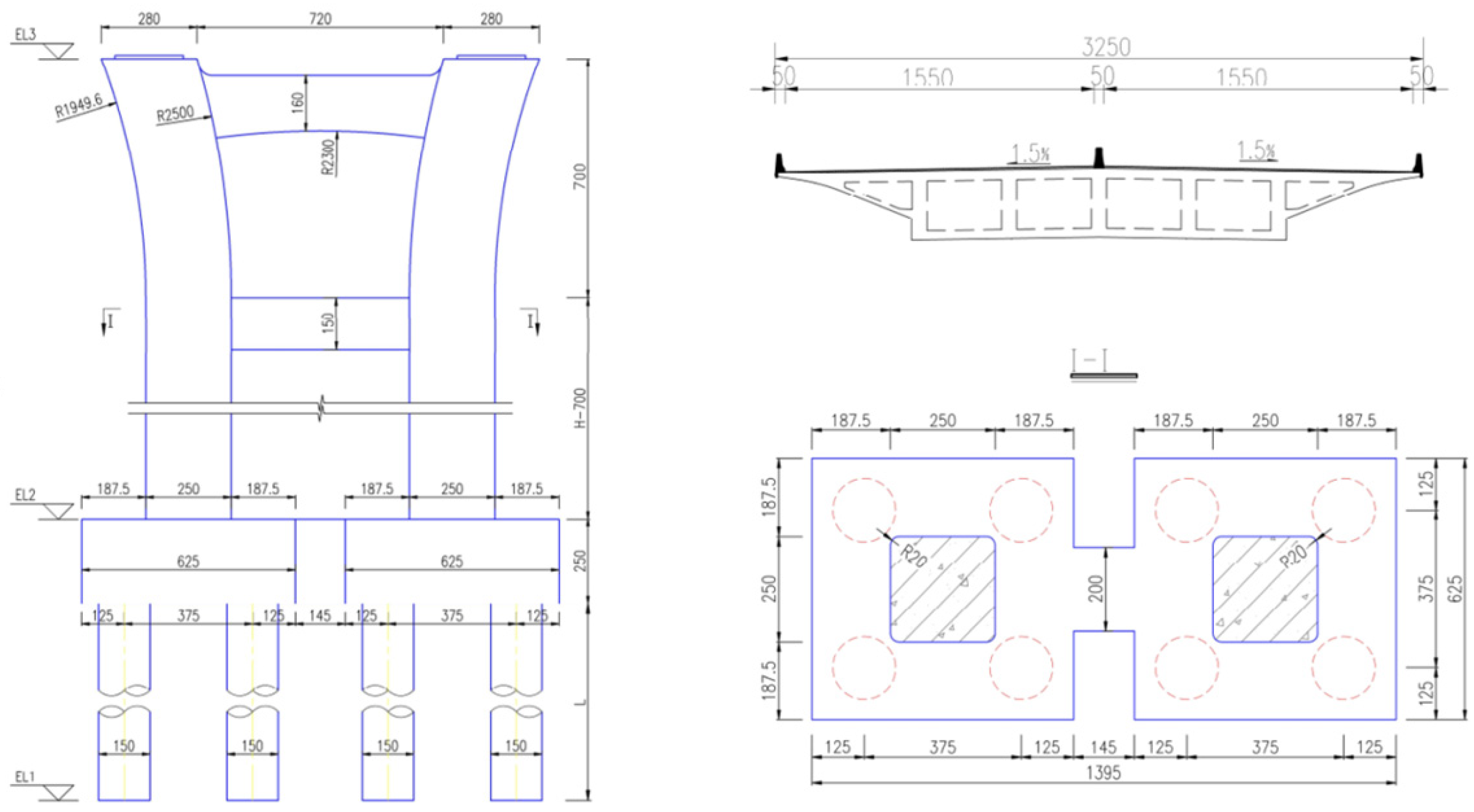
4.1. Finite Element Simulation
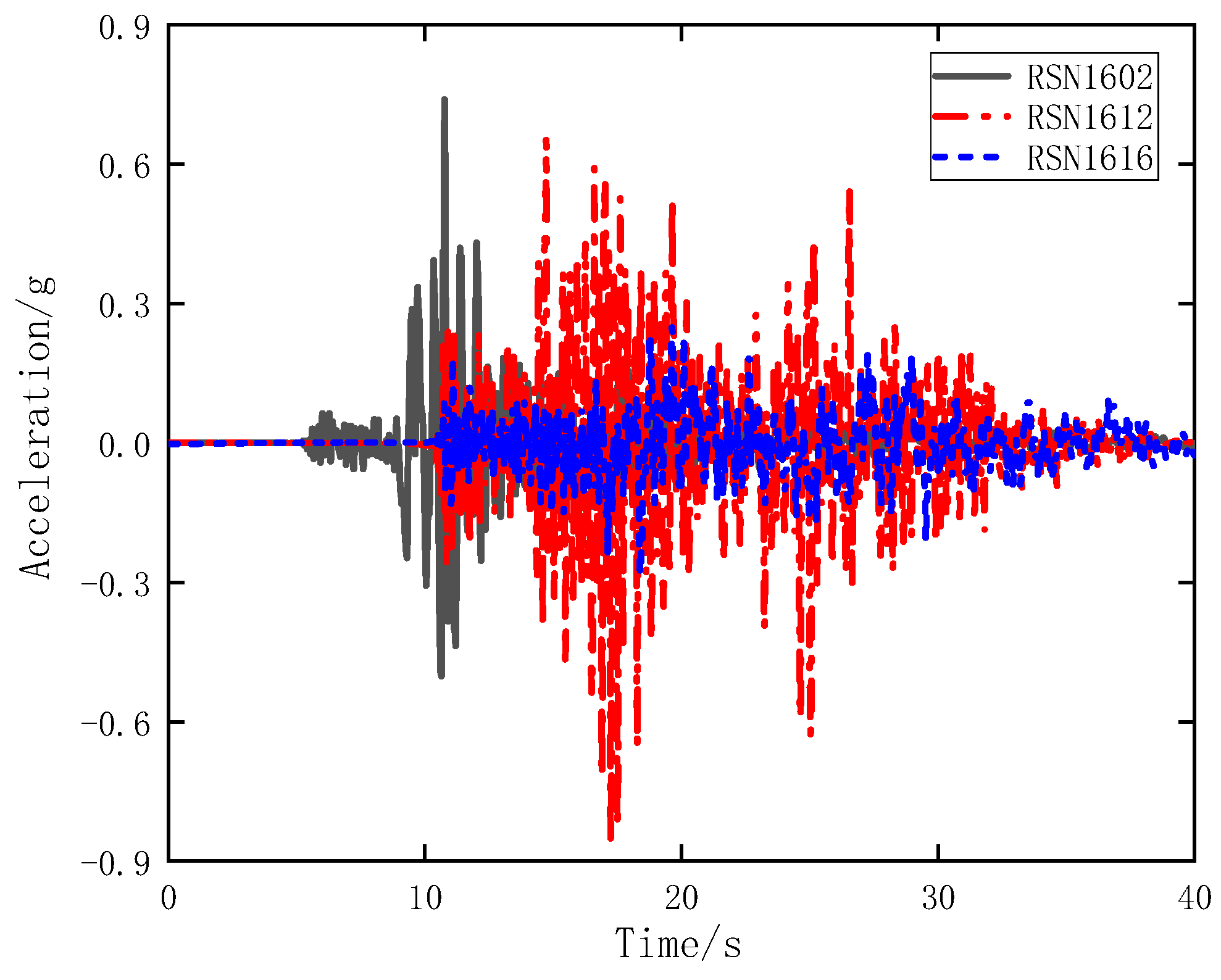
4.2. Selection of Seismic Waves
4.3. Earthquake Response Comparative Analysis
4.3.1. Bearing Displacement Response
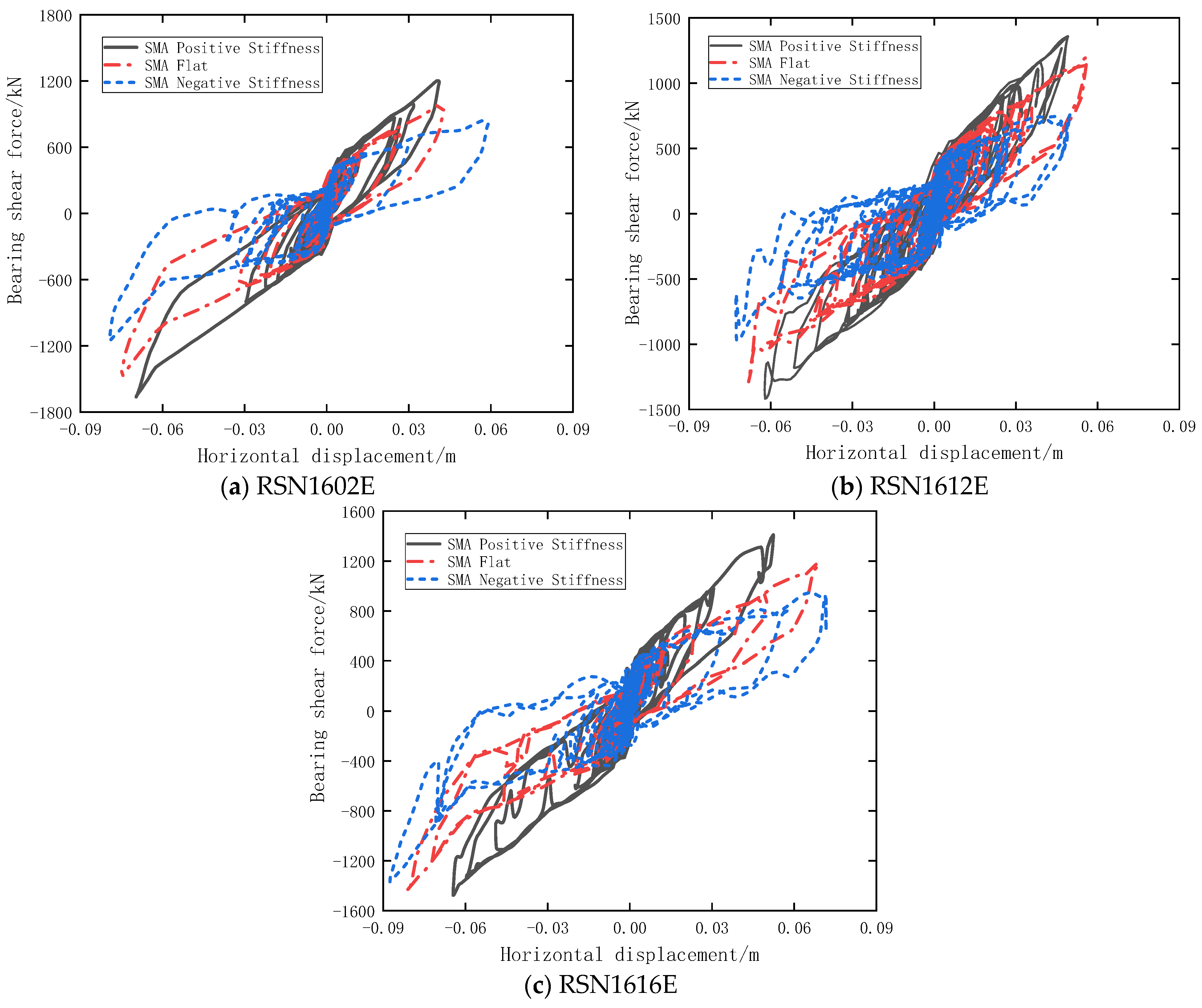
4.3.2. Support Hysteresis Curve
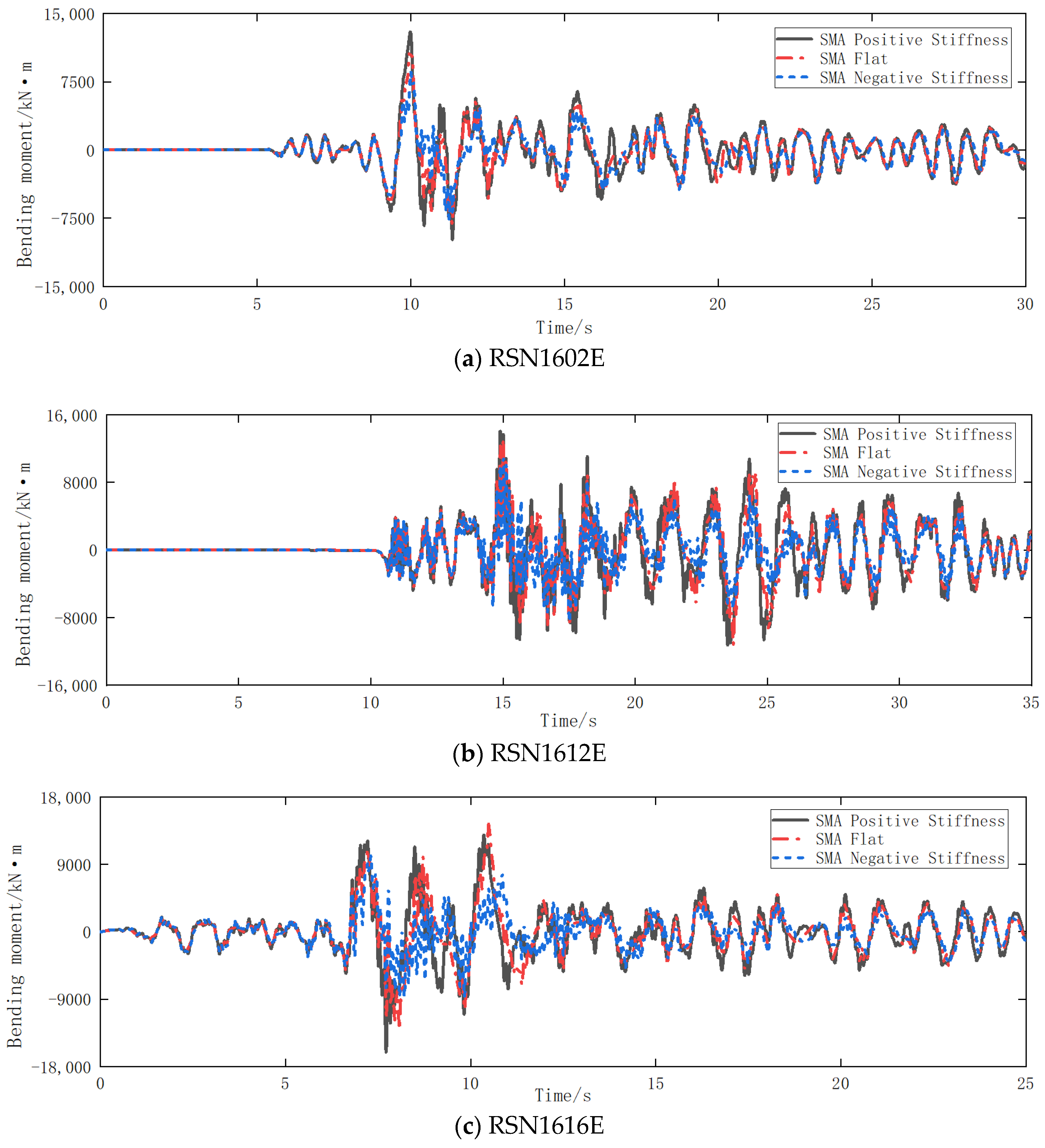
4.3.3. Pier Bottom Bending Moment Response
5. Conclusions
- SMA negative stiffness hyperboloid isolation device can provide self resetting ability for bridges. Compared with SMA positive stiffness hyperboloid isolation device, SMA negative stiffness hyperboloid isolation device can reduce the bearing displacement, increase the damping ratio and energy dissipation capacity, and partially reduce the internal force response of the substructure.
- SMA negative stiffness hyperboloid damping device reduces the bending moment at the bottom of the pier when it vibrates near the site. Compared with the three damping devices, the negative stiffness hyperboloid damping reduces the stiffness of the bridge, resulting in the reduction of the bending moment at the bottom of the pier and the amplitude of the bearing shear force.
- The magnitude of the negative stiffness of the SMA-negative stiffness hyperboloid shock absorber depends on the radius of the curved surface. The smaller the surface radius, the greater the negative stiffness effect. The stiffness optimization of the shock absorber can be achieved by adjusting the radius of the curved surface.
- With the increase of the cross-sectional area of the SMA cable, although the equivalent secant stiffness of the SMA-negative stiffness hyperboloid shock absorber increases, the energy dissipation capacity and the limit capacity increase. This will also increase the internal force response of the structure. With the increase of vertical load, the energy dissipation capacity of the SMA-negative stiffness hyperboloid shock absorber increases.
Author Contributions
Funding
Institutional Review Board Statement
Informed Consent Statement
Data Availability Statement
Conflicts of Interest
References
- Housner, G.W.; Thiel, C.C., Jr. The continuing challenge: Report on the performance of state bridges in the northridge earthquake. Earthq. Spectra 1995, 11, 607–636. [Google Scholar] [CrossRef]
- Bruneau, M.; Wilson, J.C.; Tremblay, R. Performance of steel bridges during the 1995 Hyogo-ken Nanbu (Kobe, Ja). Can. J. Civ. Eng. 1996, 23, 678–713. [Google Scholar] [CrossRef]
- Sun, X.D.; Tao, X.X.; Duan, S.S.; Liu, C.Q. Kappa (k) derived from accelerograms recorded in the 2008 Wenchuan mainshock, Sichuan, China. J. Asian Earth Sci. 2013, 73, 306–316. [Google Scholar] [CrossRef]
- Liu, C.Q.; Fang, D.J.; Zhao, L.J. Reflection on earthquake damage of buildings in 2015 Nepal earthquake and seismic measures for post-earthquake reconstruction. Structures 2021, 30, 647–658. [Google Scholar] [CrossRef]
- Li, J.Z.; Peng, T.; Yan, X. Damage investigation of girder bridges under the Wenchuan earthquake and corresponding seismic design recommendations. Earthq. Eng. Eng. Vib. 2008, 7, 337–344. [Google Scholar] [CrossRef]
- Raheem, S.E.A. Pounding mitigation and unseating prevention at expansion joints of isolated multi-span bridges. Eng. Struct. 2009, 31, 2345–2356. [Google Scholar] [CrossRef]
- Karalar, M.; Padgett, J.E.; Dicleli, M. Parametric analysis of optimum isolator properties for bridges susceptible to near-fault ground motions. Eng. Struct. 2012, 40, 276–287. [Google Scholar] [CrossRef]
- Huang, Z.; Li, H.N.; Fu, X. Optimum design of a re-centering deformation-amplified SMA damper. Eng. Mech. 2019, 36, 202–210. [Google Scholar]
- Hu, S.J.; Gu, Q.; Jiang, G.Q.; Xiong, J.G. Experimental study on seismic performance for an innovative self-centering SMA brace. Eng. Mech. 2021, 38, 109–118. [Google Scholar]
- Andrawes, B.; DesRoches, R. Comparison between shape memory alloy seismicre strainers and other bridge retrofit devices. J. Bridge Eng. 2007, 12, 700–709. [Google Scholar] [CrossRef]
- DesRoches, R.; Pfeifer, T.; Leon, R.T.; Lam, T. Full-scale tests of seismic cable restrainer retrofits for simply supported bridges. J. Bridge Eng. 2003, 8, 191–198. [Google Scholar] [CrossRef]
- Choi, E.; Nam, T.H.; Oh, J.T.; Cho, B.S. An Isolation Bearing for Highway Bridges Using Shape Memory Alloys. In Proceedings of the International Conference on Martensitic Transformations (ICOMAT05), Shanghai, China, 13–17 January 2005. [Google Scholar]
- Shinozuka, M.; Chaudhuri, S.R.; Mishra, S.K. Shape memory-alloy supplemented lead rubber bearing (SMA-LRB) for seismic isolation. Probabilist. Eng. Mech. 2015, 41, 34–45. [Google Scholar] [CrossRef]
- Wang, J.Q.; Li, S.; Dezfuli, F.H.; Alam, M.S. Sensitivity analysis and multi-criteria optimization of SMA cable restrainers for longitudinal seismic protection of isolated simply supported highway bridges. Eng. Struct. 2019, 189, 509–522. [Google Scholar] [CrossRef]
- Liang, D.; Zheng, Y.; Fang, C.; Yam, M.C.H.; Zhang, C.T. Shape memory alloy (SMA)-cable-controlled sliding bearings: Development, testing, and system behavior. Smart Mater. Struct. 2020, 29, 085006. [Google Scholar] [CrossRef]
- Wang, B.; Zhu, S.Y.; Casciati, F. Experimental study of novel self-centering seismic base isolators incorporating superelastic shape memory alloys. J. Struct. Eng. 2020, 146, 1–16. [Google Scholar] [CrossRef]
- Cao, S.S.; Ozbulut, O.E.; Shi, F.; Deng, J.D. Experimental and numerical investigations on hysteretic response of a multi-level SMA/lead rubber bearing seismic isolation system. Smart Mater. Struct. 2022, 31, 035024. [Google Scholar] [CrossRef]
- Cao, S.S.; Ozbulut, O.E.; Shi, F.; Deng, J.D. An SMA cable-based negative stiffness seismic isolator: Development, experimental characterization, and numerical modeling. J. Intel. Mat. Syst. Str. 2022, 33, 1819–1833. [Google Scholar] [CrossRef]
- Cao, S.S.; Yi, J. Shape memory alloy-spring damper for seismic control and its application to bridge with laminated rubber bearings. Adv. Struct. Eng. 2021, 24, 3550–3563. [Google Scholar] [CrossRef]
- Cao, S.S.; Ozbulut, O.E.; Wei, S.W.; Sun, Z.; Deng, J.D. Multi-level SMA/lead rubber bearing isolation system for seismic protection of bridges. Smart Mater. Struct. 2020, 29, 055045. [Google Scholar] [CrossRef]
- Wang, H.; Cao, S.S. Multi-Level Performance Shape Memory Alloy-Based Lead Rubber Bearing. In Proceedings of the 3rd International Conference on Smart City and Systems Engineering (ICSCSE), Xiamen, China, 29–30 December 2018. [Google Scholar]
- Han, Q.; Liang, X.; Wen, J.N.; Zhang, J.; Du, X.L.; Wang, Z.Q. Multiple-variable frequency pendulum isolator with high-performance materials. Smart Mater. Struct. 2020, 29, 075002. [Google Scholar] [CrossRef]
- Hiramoto, K.; Matsuoka, T.; Sunakoda, K. Simultaneous optimal design of the structural model for the semi-active control design and the model-based semi-active control. Struct. Control Health 2014, 21, 522–541. [Google Scholar] [CrossRef]
- Liu, C.Q.; Fang, D.J.; Zhao, L.J.; Zhou, J.H. Seismic fragility estimates of steel diagrid structure with performance-based tests for high-rise buildings. J. Build. Eng. 2022, 52, 104459. [Google Scholar] [CrossRef]
- Zhao, J.; Zhao, Y.; Ruan, X.H.; Gong, X.L.; Zhang, X.C. Experimental research on the seismic properties of shear wall reinforced with high-strength bars and magnetorheological dampers. Struct. Control. Health 2021, 28, e2779. [Google Scholar] [CrossRef]
- Bani-Hani, K.A.; Sheban, M.A. Semi-active neuro-control for base-isolation system using magnetor heological (MR) dampers. Earthq. Eng. Struct. Dyn. 2006, 35, 1119–1144. [Google Scholar] [CrossRef]
- Li, H.; Liu, M.; Ou, J.P. Negative stiffness characteristics of active and semi-active control systems for stay cables. Struct. Control Health 2008, 15, 120–142. [Google Scholar] [CrossRef]
- Iemura, H.; Igarashi, A.; Pradono, M.H.; Kalantari, A. Negative stiffness friction damping for seismically isolated structures. Struct Control Health 2006, 13, 775–791. [Google Scholar] [CrossRef]
- Attary, N.; Symans, M.; Nagarajaiah, S.; Reinhorn, A.M.; Constantinou, M.C.; Sarlis, A.A.; Pasala, D.T.R.; Taylor, D. Numerical simulations of a highway bridge structure employing passive negative stiffness device for seismic protection. Earthq. Eng. Struct. Dyn. 2015, 44, 973–995. [Google Scholar] [CrossRef]
- Attary, N.; Symans, M.; Nagarajaiah, S.; Reinhorn, A.M.; Constantinou, M.C.; Sarlis, A.A.; Pasala, D.T.R.; Taylor, D. Performance evaluation of negative stiffness devices for seismic response control of bridge structures via experimental shake table tests. J. Earthq. Eng. 2015, 19, 249–276. [Google Scholar] [CrossRef]
- Deng, J.D.; Hu, F.L.; Ozbulut, O.E.; Cao, S.S. Verification of Multi-level SMA/lead rubber bearing isolation system for seismic protection of bridges. Soil. Dyn. Earthq. Eng. 2020, 161, 107380. [Google Scholar] [CrossRef]
- Shao, C.X.; Cao, S.S. Test and development of SMA-based negative stiffness isolation device. Adv. Struct. Eng. 2022. [Google Scholar] [CrossRef]
- Chang, H.H.; Cao, S.S.; Ji, H.Y. SMA Negative Stiffness Damper. In Proceedings of the 2020 International Conference on Intelligent Transportation, Big Data & Smart City (ICITBS), Vientiane, Laos, 11–12 January 2020. [Google Scholar]
- Sun, T.; Lai, Z.L.; Nagarajaiah, S.; Li, H.N. Negative stiffness device for seismic protection of smart base isolated benchmark building. Struct. Control Health 2017, 24, e1968. [Google Scholar] [CrossRef]
- Yang, Q.R.; Ran, M.L.; He, W.F.; Yu, W.X.; Liu, W.G. Study on seismic response of isolated structure based on damping negative stiffness device. J. Vib. Eng. 2018, 31, 920–929. [Google Scholar]
- Liu, M.; Zhou, P.; Li, H. Novel self-centering negative stiffness damper based on combination of shape memory alloy and prepressed springs. J. Aerosp. Eng. 2018, 31, 04018100. [Google Scholar] [CrossRef]
- Iemura, H.; Pradono, M.H. Simple algorithm for semi-active seismic response control of cable-stayed bridges. Earthq. Eng. Struct. Dyn. 2005, 34, 409–423. [Google Scholar] [CrossRef]
- Iemura, H.; Pradono, M.H. Advances in the development of pseudo-negative-stiffness dampers for seismicre sponse control. Struct. Control Health 2009, 16, 784–799. [Google Scholar]
- Ozbulut, O.E.; Daghash, S.; Sherif, M.M. Shape memory alloy cables for structural applications. J. Mater. Civ. Eng. 2016, 28, 04015176. [Google Scholar] [CrossRef]
- Auricchio, F.; Taylor, R.L. Shape-memory alloys: Modelling and numerical simulations of the finite-strains uperelastic behavior. Comput. Methods Appl. Mech. Eng. 1997, 143, 175–194. [Google Scholar] [CrossRef]


| Seismic Wave | Positive Stiffness | Flat | Negative Stiffness | |
|---|---|---|---|---|
| RSN1602E | Amplitude/mm | 66.35 | 75.80 | 78.78 |
| RSN1612E | Amplitude/mm | 58.64 | 68.25 | 72.78 |
| RSN1616E | Amplitude/mm | 61.75 | 81.30 | 95.58 |
| Seismic Wave | Positive Stiffness | Flat | Negative Stiffness | |
|---|---|---|---|---|
| RSN1602E | Amplitude/kN | 1695 | 1512 | 906 |
| RSN1612E | Amplitude/kN | 1599 | 1298 | 763 |
| RSN1616E | Amplitude/kN | 1689 | 1535 | 1325 |
| Seismic Wave | Positive Stiffness | Flat | Negative Stiffness | |
|---|---|---|---|---|
| RSN1602E | Amplitude/kN·m | 13,340 | 11,224 | 6596 |
| RSN1612E | Amplitude/kN·m | 14,866 | 13,166 | 9395 |
| RSN1616E | Amplitude/kN·m | 16,084 | 14,628 | 10,137 |
Publisher’s Note: MDPI stays neutral with regard to jurisdictional claims in published maps and institutional affiliations. |
© 2022 by the authors. Licensee MDPI, Basel, Switzerland. This article is an open access article distributed under the terms and conditions of the Creative Commons Attribution (CC BY) license (https://creativecommons.org/licenses/by/4.0/).
Share and Cite
Chang, H.; Liu, L.; Jing, L.; Lu, J.; Cao, S. Study on Damping Performance of Hyperboloid Damper with SMA-Negative Stiffness. Buildings 2022, 12, 1111. https://doi.org/10.3390/buildings12081111
Chang H, Liu L, Jing L, Lu J, Cao S. Study on Damping Performance of Hyperboloid Damper with SMA-Negative Stiffness. Buildings. 2022; 12(8):1111. https://doi.org/10.3390/buildings12081111
Chicago/Turabian StyleChang, Huahui, Leifei Liu, Li Jing, Jingyan Lu, and Sasa Cao. 2022. "Study on Damping Performance of Hyperboloid Damper with SMA-Negative Stiffness" Buildings 12, no. 8: 1111. https://doi.org/10.3390/buildings12081111
APA StyleChang, H., Liu, L., Jing, L., Lu, J., & Cao, S. (2022). Study on Damping Performance of Hyperboloid Damper with SMA-Negative Stiffness. Buildings, 12(8), 1111. https://doi.org/10.3390/buildings12081111