Article

Formwork System Selection in Building Construction Projects Using an Integrated Rough AHP-EDAS Approach: A Case Study

Department of Civil Engineering, Istanbul Technical University, Istanbul 34469, Turkey
*
Author to whom correspondence should be addressed.
Buildings 2022, 12(8), 1084; https://doi.org/10.3390/buildings12081084
Submission received: 20 June 2022 / Revised: 18 July 2022 / Accepted: 22 July 2022 / Published: 25 July 2022
(This article belongs to the Section Construction Management, and Computers & Digitization)

Abstract

:
The successful completion of reinforced concrete (RC) building construction projects depends, in part, on selecting the appropriate formwork system (FWS) since it may significantly affect the project’s cost, time, and quality performance factors. The selection of the FWS depends on a number of compromising and conflicting criteria, while several FWS alternatives may be available. Therefore, the FWS selection has mostly been treated as a multi-criteria-decision-making (MCDM) problem. Although various MCDM methods have been employed to address the FWS selection problem, none have considered the subjectivity and uncertainty arising from a group decision-making process. This study aims to fill this knowledge gap by proposing an integrated approach using recently developed MCDM methods with rough numbers. In the integrated approach, first, a decision-making team is formed to develop the decision hierarchy. Then, the rough analytic hierarchy process (R-AHP) is used to determine rough criteria weights, followed by the rough evaluation based on the distance from average solution (R-EDAS) method to rank the FWS alternatives. Finally, the results are compared using different rough MCDM methods to ensure the stability of the proposed approach. The proposed approach is applied to a real-life building construction project in Turkey to select the most appropriate FWS. The integrated approach was found to be effective, and it was recommended to be used for future FWS selection problems. The proposed integrated approach in this study may be used as a decision support tool for construction professionals and experts to select the FWS in building construction projects.

1. Introduction

The formwork system (FWS) gives the geometry and strength required by the reinforced concrete (RC) structure to attain the desired form and structural design properties of the cured concrete [1,2]. In addition, formwork-related activities such as erecting the FWS, placing the rebar, pouring the concrete, and stripping the FWS are performed continuously throughout the building construction project [3,4]. Therefore, the FWS can have significant effects on the construction project’s time, cost, and quality performance [5,6,7,8]. In general, the FWS may account for up to two-thirds of the entire cost of the RC structural frame [9], and it can significantly affect the total duration of the project since it influences the floor cycle-time of building construction projects [10]. The planning and designing of the FWS can be a major challenge for construction professionals as they are both time-consuming and complex processes [11]. Moreover, the incorrect planning of the FWS may be a significant source of material and time waste in the later phases of the construction project [12]. Therefore, the selected FWS may also affect the sustainability performance of the RC building construction project [13]. In this regard, due to the high level of material waste in RC construction [14,15], the sustainability of the FWS has become an important factor in recent years [16].
The structural design and the selected FWS may affect an RC building construction project’s constructability [17]. Revaluating the building’s structural design in light of the available FWS alternatives may improve constructability and potentially lower the unit cost of the RC structure [18]. In other words, improving the constructability in RC building construction projects may depend on selecting the appropriate FWS [19]. Furthermore, formwork activities (e.g., erecting, stripping, or moving of the FWS) are considered especially dangerous for construction workers due to their association with a high level of construction accidents [20,21]. Hence, the FWS may also affect the safety performance of the RC building construction project. In building construction projects, labour productivity can be measured as a function of the floor cycle time of the FWS [22]. Since different FWS may have varying floor cycle times, labour productivity is another project performance factor affected by the selected FWS [23]. Consequently, selecting the appropriate FWS can save project costs and time, and it can be a critical component in successfully implementing an RC building construction project [8,24,25].
Since the early 1990s, several studies have been conducted to identify the FWS selection criteria and the FWS alternatives to solve the FWS selection problem [26]. The selection of the appropriate FWS depends on various compromising and conflicting criteria, some of which can be interdependent and interrelated [27]. Moreover, the widespread use of industrial FWSs (i.e., modular and reusable FWSs) and technical advancements in formwork engineering have led to the inclusion of new FWS selection criteria and new FWS alternatives for building construction projects [22,27,28]. Therefore, scholars and construction professionals have treated the FWS selection as a multi-criteria decision-making (MCDM) problem based on several FWS selection criteria and FWS alternatives, e.g., [29,30].
The FWS selection is a group decision-making process conducted by experts in the field of formwork engineering [1]. Therefore, consideration of the subjective judgments and the uncertainty in the collected data from these experts in the MCDM model may provide an improved and objective selection process [31]. Although previous studies greatly contribute to the FWS selection problem, they do not consider the subjectivity and uncertainty in the collected data from the decision-making team. The main objective of this study is not to develop a new MCDM methodology but to propose an integrated approach that employs the recently developed rough analytic hierarchy process (R-AHP) and rough evaluation based on distance from average solution (R-EDAS) methods to solve the FWS selection problem. Several studies have combined the AHP and EDAS methods to solve a specific selection problem, e.g., [32]. For instance, Stevic et al. [33] used an integrated fuzzy AHP-EDAS approach to evaluate suppliers in an uncertain environment. Similarly, Karatop et al. [34] utilized the fuzzy AHP and fuzzy EDAS methods to determine the best renewable energy alternative in Turkey. In addition, Toan et al. [35] combined the AHP and EDAS methods to evaluate video conferencing software alternatives and used grey numbers to integrate the subjective judgments of the experts in their case study. In this study’s proposed approach, the subjective opinions of the experts are aggregated, and the uncertainty in the data is incorporated using the rough set theory and rough numbers. The R-AHP method is used to determine the rough weights of the FWS selection criteria, and the R-EDAS method is employed to evaluate and rank the FWS alternatives. In addition, a comparative analysis using other rough MCDM methods is proposed to ensure the stability and validity of the final rankings of the FWS alternatives. In order to illustrate the effectiveness of the proposed approach for the FWS selection problem, it was applied to a real-life building construction project in Turkey.
This study is intended to serve as a decision support tool for construction professionals and experts participating in the FWS decision-making process and is regarded as a considerable contribution to the body of knowledge regarding the FWS selection problem. As the selected FWS may impact the time, cost, quality, safety, sustainability, labour productivity, and the constructability of a building construction project [17,23,36], the integrated approach proposed in this study may be utilized to improve these project performance factors.

2. Literature Review

The selection of FWSs in building construction projects has been the focus of several studies from 1989 until 2022. The majority of these studies fall into two main categories: (1) studies that focus on identifying and/or ranking the quantitative and qualitative FWS selection criteria, e.g., [24,37], and (2) studies that propose solutions to select the most appropriate FWS, which is affected by various compromising and conflicting criteria, e.g., [10,38]. The studies related to the identification and/or ranking of FWS selection criteria have been summarized in a single body of knowledge in Terzioglu et al.’s [27] study, which is a critical review of the relevant literature for building construction projects. Since the main objective of this study is to propose an integrated MCDM approach for selecting FWSs, this section will focus mainly on studies that attempted to solve the FWS selection problem. Value engineering, knowledge-based guidelines, rule-based expert systems, neural networks (NNs), and several MCDM methods are among the proposed solutions for the FWS selection problem. The following is a brief review of these studies in chronological order:
Hanna and Sanvido [39] developed a knowledge-based systematic guideline, specifically for the contractor’s formwork planner, to select vertical FWSs based on Hanna’s factors and FWS alternatives [37]. In this study, five vertical FWS alternatives, including conventional FWS, ganged FWS, jump FWS, slip FWS, and self-raising FWS, were identified for building construction projects in the USA. Hanna et al. [26] presented a rule-based expert system to assist decision-makers and formwork design engineers in selecting vertical and horizontal FWS alternatives for building construction projects in the USA. This study considered traditional wood FWS, conventional metal FWS, flying truss FWS (i.e., Table FWS), column-mounted shoring FWS, and tunnel FWS as horizontal FWS alternatives. Kamarthi et al. [40] and Hanna and Senouci [41] proposed Neural Network (NN) models for the vertical and horizontal FWSs selection problem, respectively, using the previously identified factors and FWS alternatives. Abdel-Razek [42] utilized a value engineering approach to guide decision-makers in the FWS selection process for building construction projects. Elazouni et al. [43] proposed an integrated approach to estimate the acceptability of new horizontal FWSs (e.g., telescopic beam and prop FWS, telescopic beam and shore-brace FWS, shore-brace FWS, s-beam and prop FWS, drop-head FWS), by combining the Analytical Hierarchy Process (AHP) method with NN models. Based on previously developed NN models for the FWS selection problem, e.g., [41], Tam et al. [44] and Shin [45] introduced a probabilistic NN model and an artificial NN model, respectively, to select the most appropriate FWS. In Shin’s [32] study, horizontal FWS alternatives such as aluminium panel FWS, conventional FWS, Table FWS, and drop-head FWS were identified as the most commonly utilized FWSs in Korea’s high-rise building construction projects. Elbeltagi et al.’s [46] study for the selection of horizontal FWS (e.g., conventional FWS, Table FWS, shore-brace FWS, and drop-head FWS), and Elbeltagi et al.’s [29] study for the selection of vertical FWS (e.g., traditional FWS, panel FWS, single-sided FWS, crane-climbing FWS, and self-climbing FWS) both used a knowledge-based systematic guideline and fuzzy logic to determine the most appropriate FWS in building construction projects in Egypt. It should be noted that, in these studies, fuzzy logic was applied to convert linguistic input and output variables associated with FWS selection criteria and FWS alternatives, respectively, to their fuzzy forms. Shin et al. [10] employed a boosted decision tree (BDT) model to select horizontal FWSs in high-rise building construction projects in Korea, based on the most important FWS alternatives and factors affecting the FWS selection identified by Shin [45]. Several studies have proposed well-known MCDM methods to solve the FWS selection problem using experts’ evaluations based on crisp numbers. For instance, Krawczyska-Piechna [47] proposed the Technique for Order of Preference by Similarity to Ideal Solution (TOPSIS) method to select the most appropriate FWS for building construction projects in Poland. Martinez et al. [48] proposed the Choosing by Advantages (CBA) method for the FWS selection problem in Ecuador. However, in these studies, information regarding the various types of FWS alternatives was not provided. Basu and Jha [38] applied the AHP method to solve the FWS selection problem in the Indian building construction sector, based on the FWS selection criteria identified by Hanna et al. [26]. Likewise, Hansen et al. [30] employed the AHP method to select among two FWS alternatives (e.g., conventional FWS and aluminium FWS) based on Indonesia’s most significant FWS selection criteria. Teja et al. [49] developed a fuzzy rule-based system to select vertical FWSs by combining fuzzy logic with the rule-based expert system introduced by Hanna et al. [26]. This study determined that traditional FWS, conventional FWS, panel FWS, crane-climbing FWS, self-climbing FWS, and plastic FWS are the most frequently utilized FWSs in the Indian building construction sector.
In summary, most studies addressing the FWS selection problem employed techniques such as rule-based expert systems, NNs, and other MCDM methods. However, no study has integrated the subjective judgments of the decision-makers into the FWS selection process or considered the vagueness in the collected data from the experts in their evaluation to select the most appropriate FWS. The FWS selection is a group decision-making process [29]. In addition, the early involvement of different stakeholder groups (e.g., the contractor and the formwork fabricator (FWF)) in the planning and design stages of the FWS may improve the time and the cost performance of a building construction project [50,51]. On the other hand, the perspectives and perceptions regarding the FWS alternatives and the importance level of FWS selection criteria of different construction professionals (i.e., experts in the decision-making team) may vary [52]. However, uncertainty arises when decision-makers have varying opinions on alternatives [53]. This might result from inadequate information or the different backgrounds of the decision-makers [53]. Therefore, the subjective judgments and the vagueness in data obtained from the experts should be considered when using MCDM methods for the FWS selection problem. In this regard, using the mathematical tools provided by uncertainty theories such as fuzzy set theory and rough set theory may improve the objectivity of the decision-making process [54,55]; in this case, for evaluating FWS alternatives. To the authors’ knowledge, no study involving MCDM methods to solve the FWS selection problem has incorporated uncertainty into the decision-making process. The main objective of this study is to fill the critical knowledge gap by using rough numbers to evaluate the FWS selection criteria and alternatives. For this purpose, an integrated MCDM approach is proposed, which will be discussed in the following section of this study.

3. Research Methodology

The main objective of this study is to propose an integrated MCDM approach to solve the FWS selection problem using rough numbers, which is intended to incorporate the vagueness and the subjectivity of expert evaluation in the decision-making process. The proposed approach may serve as a valuable tool for construction professionals involved in the FWS’s decision-making process. In addition, the proposed research methodology is in accordance with prior construction management studies, in which integrated MCDM methods are employed to solve a specific selection problem, e.g., [56,57,58,59,60]. As demonstrated in Figure 1, the main stages of the proposed research methodology are as follows:

3.1. Formation of the Decision-Making Team

The selection of the FWS may be performed by different stakeholder groups, such as the engineer, the contractor, and/or the FWF, depending on the project delivery system, construction method, type of structure, and capacity of the stakeholder [4,52]. In addition, there may be significant statistical differences or disagreements in the relative importance level of FWS selection criteria among different groups of construction professionals (e.g., company owners, project managers, construction managers, site engineers, planning engineers, procurement engineers, technical office engineers, formwork design, and/or formwork sales engineers) [8,52].
Therefore, the type of the selected FWS (i.e., the FWS alternative) may depend on the perspective and perception of the different groups of construction professionals. However, the early involvement of all stakeholders during the planning and design stage of the FWS may significantly improve the performance factors of a building construction project, such as the time, the cost, and the quality, while reducing material and time waste in the FWS supply chain [4,52]. Furthermore, selecting the most appropriate FWS requires professional experience in the field of formwork engineering as well as expert advice [41], which should also provide the company owners with cost-effective FWS solutions [61]. As a result, FWS selection is a group decision-making process [1] and may involve decision-makers with different professional backgrounds. In the first stage of the proposed approach, a decision-making team is formed, whose members are experts in formwork engineering. In addition, the decision-making team should have the necessary proficiency and knowledge of the project-specific requirements since FWS selection may greatly depend on the project characteristics (e.g., structural design of the building construction project) [8,17,52].

3.2. Literature Review and Extraction of Experts’ Opinion

A total of 35 FWS selection criteria for building construction projects were identified after a comprehensive literature review. Terzioglu et al.’s study [27] provides a detailed discussion of these 35 FWS selection criteria and a critical review of the relevant literature. Furthermore, Terzioglu et al. [52] conducted a questionnaire study in the Turkish building construction sector, contributing to the applicability and validity of these FWS selection criteria. Table 1 illustrates the FWS selection criteria identified in the literature review and their brief descriptions. It should be noted that the criteria in Table 1 represent the complete set of FWS selection criteria in building construction projects. As part of the second stage of the research methodology, face-to-face interviews are used to elicit the expert’s opinion on the general applicability (i.e., independent from the case study) of the 35 FWS selection criteria. However, some FWS selection criteria may be more critical than others [30,61], and the number of the required criteria for the FWS selection process may vary from case to case [48]. Hence, if necessary, the number of FWS selection criteria may be reduced depending on the project-specific requirements, which will be explained in the next stage of the proposed approach.

3.3. Development of the Decision Hierarchy

The first step in developing the decision hierarchy is identifying the project-related FWS selection criteria and, second, the FWS alternatives. The FWSs for building construction projects are typically classified as either horizontal FWSs for concreting beams and slabs and vertical FWSs for concreting walls and columns [46]. The horizontal and vertical FWS alternatives are in principle different from each other since the fresh concrete load can be applied vertically or horizontally on the FWS [9,24], and the allowable stripping time of formwork for horizontal and vertical structural members are significantly different from each other [65,66]. Moreover, horizontal FWS require temporary shoring structures (e.g., scaffolding systems, telescopic props) to support the FWS and transfer the fresh concrete loads to the ground, whereas vertical FWSs require horizontal structural members (e.g., tie-rods, bracing) to transfer these loads [18]. In this regard, the selection of horizontal and vertical FWSs (i.e., horizontal and vertical FWS alternatives) are treated separately from each other as they have different functions [26]. In addition, numerous FWS alternatives may be available on the local market [29], some of which can be inappropriate for a building construction project. For instance, crane-independent self-climbing formwork (i.e., hydraulic climbing systems) can improve time and cost performance in high-rise buildings but may not be effective and efficient in low-rise or mid-rise buildings [67]. Furthermore, the transportation cost of an FWS can be an essential factor, especially in developing countries where some FWSs may not be available and must be imported from other countries [27].
The FWS selection criteria associated with the local conditions (e.g., weather conditions, site access) and the structural design (e.g., floor-to-floor height, total building height) of the building construction project have a positive and significant influence on the FWS–FWF characteristics (e.g., FWS durability, FWF technical support) related criteria [8,52]. The compatibility of the FWS with the building construction project’s structural design may also significantly affect the FWS selection process [68]. Consequently, the selection of the FWS is highly dependent on the project-specific structural design and local conditions, which the decision-making team may consider. Similarly, the cost (e.g., the initial cost of the FWS, the labour cost of the FWS) and the performance (e.g., speed of construction, labour productivity) related criteria are significantly influenced by the selected FWS [8,52].
Therefore, the project budget and schedule can be two important constraints that the decision-making team may consider while identifying the relevant FWS selection criteria and alternatives. Hence, based on previous literature review and project-specific requirements, the decision-making team identifies the FWS selection criteria. In addition, the decision-making team determines the FWS alternatives based on appropriateness and market availability. The last step of this stage is the decision-making team’s approval of the decision hierarchy. If there is a disagreement among the experts related to the decision hierarchy, then the list of FWS selection criteria and FWS alternatives related to the building construction project is modified until a consensus can be reached. The general structure of the decision hierarchy [69] is shown in Figure 2:

3.4. Determination of the Criteria Weight (R-AHP) and Ranking of the Alternatives (R-EDAS)

This study proposes an integrated approach that incorporates the R-AHP and the R-EDAS methods for selecting the most appropriate FWS for building construction projects. Therefore, preliminaries of the rough set theory and rough numbers will be presented first, followed by the R-AHP and the R-EDAS methodologies utilized in the proposed MCDM approach of this study.

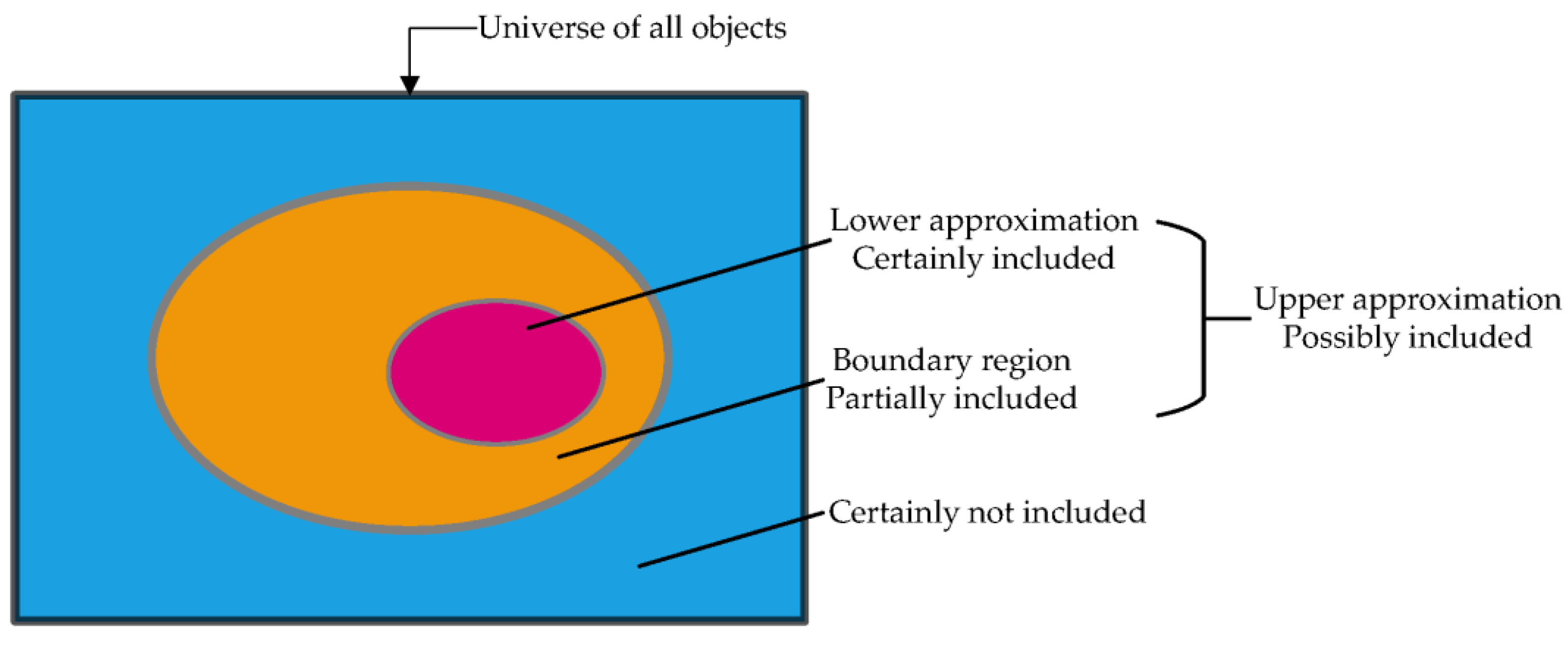
3.4.1. Rough Set Theory and Rough Numbers

Since FWS selection involves a group decision-making process, the use of MCDM methods in this selection problem presents two major challenges: (1) how to combine the individual judgements and preferences of different experts and (2) how to manage their subjectivity. Several studies have successfully integrated the subjective judgments of decision makers into the decision-making process using uncertainty theories and different MCDM methods. For instance, Xu et al. [70] used the fuzzy decision-making trial and evaluation laboratory (DEMATEL) method to determine the critical barriers to the development of hydrogen refuelling stations in China. Similarly, Wu et al. [71] utilized the fuzzy MCDM technique to account for the vagueness of judgments when assessing renewable energy sources in China. Therefore, in this study, rough numbers are proposed to address these issues. Since its introduction by Pawlak [72], the rough set theory has demonstrated its effectiveness as a mathematical tool to deal with uncertainty in the data [73]. As an extension to rough set theory, the use of rough numbers [74] in combination with MCDM methods to solve a particular selection problem has gained popularity in recent years, especially in construction management, e.g., [75,76]. Rough set theory has certain advantages over other set theories, such as fuzzy set theory, which also deals with uncertainty, vagueness, and subjectivity in decision-making. For instance, according to Li et al. [54], a rough number has two main advantages over a fuzzy number: (1) the descriptive information from a rough number can more accurately represent the actual perceptions of experts and decision-makers, hence increasing the objectivity of the original data, and (2) a rough number incorporates the perspectives of all decision-makers combined, not just those of individual decision-makers. Moreover, regarding a rough number, the measurement of uncertainty is based on the vagueness already existing in the data itself [77]. In other words, a rough number is determined directly from the collected data, whereas the fuzzy number is a predefined value [54]. Hence, in contrast to other methods, the rough set theory relies solely on the data’s intrinsic knowledge and requires no external assumptions or auxiliary information [78,79].
A rough number typically consists of a lower limit, an upper limit, and a rough boundary interval that is dependent exclusively on the original data [78]. In addition, based on the lower and upper approximations, each vague concept may be expressed as a couple of exact concepts [80], as shown in Figure 3.
Suppose U is the universe which contains all objects, Y is an arbitrary object of U, R is a set of t classes (G1, G2, …, Gt) that cover all the objects in U, R = {G1, G2, …, Gt}. If these classes are ordered as G1 < G2 < … < Gt, then ∀YU, GqR, 1 ≤ qt, the lower approximation ( A p r _ (Gq)), upper approximation ( A p r ¯ (Gq)), and boundary region (Bnd(Gq)) of classes Gq are defined as [78]:
A p r _ ( G q ) = { Y   U / R ( Y ) G q }
A p r ¯ ( G q ) = { Y   U / R ( Y ) G q }
B n d ( G q ) = { Y   U / R ( Y ) G q }                                                       = { Y   U / R ( Y ) > G q } { Y   U / R ( Y ) < G q }
then, Gq can be represented by a rough number (RN(Gq)), which is determined by its corresponding lower limit ( L i m _ (Gq)) and upper limit ( L i m ¯ (Gq)), where:
L i m _ ( G q ) = 1 M L { Y A p r _ ( G q ) } R ( Y )
L i m ¯ ( G q ) = 1 M U { Y A p r ¯ ( G q ) } R ( Y )
R N ( G q ) = [ L i m _ ( G q ) , L i m ¯ ( G q ) ]
where ML and MU are numbers of objects contained in A p r _ (Gq) and A p r ¯ (Gq), respectively. The difference is defined as a rough boundary interval (IRBnd (Gq)):
I R B n d ( G q ) = L i m ¯ ( G q ) L i m _ ( G q )
A large value of the rough boundary interval denotes greater vagueness, whereas a lower number indicates greater precision [81]. According to Zhai et al. [74], for two rough numbers   R N ( α ) = [ L i m _ ( α ) , L i m ¯ ( α ) ] and R N ( β ) = [ L i m _ ( β ) , L i m ¯ ( β ) ] the arithmetic operations of addition, subtraction, multiplication, and division can be stated as follows:
R N ( α ) + R N ( β ) = [ L i m _ ( α ) + L i m _ ( β ) , L i m ¯ ( α ) + L i m ¯ ( β ) ]
R N ( α ) R N ( β ) = [ L i m _ ( α ) L i m ¯ ( β ) , L i m ¯ ( α ) L i m _ ( β ) ]
R N ( α ) × R N ( β ) = [ L i m _ ( α ) × L i m _ ( β ) , L i m ¯ ( α ) × L i m ¯ ( β ) ]
R N ( α ) ÷ R N ( β ) = [ L i m _ ( α ) ÷ L i m ¯ ( β ) , L i m ¯ ( α ) ÷ L i m _ ( β ) ]
In addition, for a nonzero constant μ, the scalar multiplication of a rough number R N ( α ) is:
μ × R N ( α ) = [ μ × L i m _ ( α ) , μ × L i m ¯ ( α ) ]

3.4.2. R-AHP Method for Criteria Weighting

The AHP method is frequently utilized in various decision-making problems in construction management, particularly for weighing criteria [82,83]. The AHP method enables the measurement of preference consistency, manipulation of different decision-makers and management of decision-making incorporating subjective judgements [78]. In addition, the AHP method is an excellent tool for analysing the selection of technological systems [69], including industrial FWSs. As described in the preceding sections of this study, the selection of the FWS may include several decision-makers with diverse professional backgrounds and motivations towards the building construction project, as well as with different perceptions regarding the relative importance level of FWS selection criteria. Since the decision-making process involves subjectivity and ambiguity, this study proposes using rough numbers to aggregate individual assessments and calculate the weights of the FWS selection criteria in combination with the AHP method (i.e., R-AHP).
The methodology for the R-AHP is presented as follows [78,84]:
Step 1: The decision-making team of k-experts is formed to identify the FWS selection criteria and the FWS alternatives as well as to develop the decision hierarchy, which is described in stages 1, 2, and 3 of the proposed approach in this study. The objective is placed on the top of the hierarchical structure, followed by the FWS selection criteria in the middle and the FWS alternatives at the bottom.
Step 2: Development of a group pairwise comparison matrix by asking each expert in the decision-making team to conduct pairwise comparisons of the FWS selection criteria to determine the weights of the criteria. The lth expert’s pairwise comparison matrix Bl is given as follows:
B l = [ 1 x 12 l x 1 m l x 21 l 1 x 2 m l x m 1 l x m 2 l 1 ] m × m
where, x e r l (1 ≤ em, 1 ≤ rm, 1 ≤ lk) is the relative importance of criterion e on criterion r based on Saaty’s scale [85] given by lth expert, m is the number of FWS selection criteria, and k is the total number of experts. In addition, x e e l = 1, x r e l =1/ x e r l and x e r l 0 .
Calculation of the maximum eigenvalue λ m a x l of matrix Bl and computation of the consistency index C I l = ( λ m a x l m ) / ( m 1 ) .
Determining the random consistency index RI [86] using Table A1 based on the total number of FWS selection criteria m and calculation of the consistency ratio C R l = C I l / R I .
Conducting the consistency test for each comparison matrix Bl. If C R l < 0.1, the comparison matrix Bl is acceptable, otherwise the expert’s evaluation should be adjusted.
Finally, each expert’s judgment is aggregated in the form of an integrated comparison matrix B ˜ as follows:
B ˜ = [ 1 x ˜ 12 x ˜ 1 m x ˜ 21 1 x ˜ 2 m x ˜ m 1 x ˜ m 2 1 ] m × m
where, x ˜ e r = { x e r 1 , x e r 2 , , x e r k } , x ˜ e r is the sequence of relative importance of criterion e on criterion r, which consists of k experts’ evaluation.
Step 3: Using Equations (1)–(6), translate the elements x e r l in the integrated comparison matrix B ˜ into rough number R N ( x e r l ) :
R N ( x e r l ) = x e r l L , x e r l U
where x e r l L is the lower limit, and x e r l U is the upper limit of R N ( x e r l ) . Then the rough sequence R N ( x ˜ e r ) is obtained as follows:
R N ( x ˜ e r ) = { x e r 1 L , x e r 1 U , x e r 2 L , x e r 2 U , , x e r k L , x e r k U }
The average rough number R N ( x e r ) is calculated using the rough arithmetic Equations (8)–(10):
R N ( x e r ) = x e r L , x e r U
x e r L = x e r 1 L + x e r 2 L + + x e r k L k
x e r U = x e r 1 U + x e r 2 U + + x e r k U k
where x e r L is the lower limit and x e r U is the upper limit of average rough number R N ( x e r ) .
The rough comparison matrix M is formed as follows:
M = [ 1 , 1 x 12 L , x 12 U x 1 m L , x 1 m U x 21 L , x 21 U 1 , 1 x 2 m L , x 2 m U x m 1 L , x m 1 U x m 2 L , x m 2 U 1 , 1 ] m × m
Step 4: In the final step the rough-based criteria weights w i and its normalized counterpart w i   are calculated as follows:
w i = w i L , w i U = r = 1 m x e r L m , r = 1 m x e r U m
w i = w i max ( w i U ) = w i L max ( w i U ) , w i U max ( w i U )   i = 1 , 2 , , m

3.4.3. R-EDAS Method for Alternative Evaluation

In general, the AHP method by itself can yield good results in MCDM problems, but better results are frequently obtained by combining AHP with other MCDM techniques [87]. The EDAS method is one of the recently developed MCDM methods [88] and its extended version using rough numbers (i.e., R-EDAS) is even more recent [76,89]. Therefore, only a few studies in the literature combine rough numbers with the EDAS method, e.g., [76,89]. However, the EDAS method is an essential decision-making tool in everyday situations where parameter conflicts are frequent [76]. In addition, its popularity among the MCDM methods to solve engineering problems and/or business decision-making problems is rising, e.g., [90,91,92,93,94]. Moreover, the EDAS method is frequently combined with the AHP method in its traditional or extended forms [95].
The R-EDAS method provides objective aggregation of experts’ evaluation by considering ambiguity and subjectivity in the group decision-making process [76]. In this method, the assessments of the alternatives are based on the measurements of positive and negative deviations/distances from the average solution, which is evaluated using all criteria [88]. In accordance with the previously developed decision hierarchy consisting of m FWS selection criteria (Cm), n FWS alternatives (An), and k experts, and in line with Stevic et al.’s study [89], the following steps are presented for the R-EDAS method:
Step 1: The individual decision matrices of k experts are transformed into a single group rough matrix GRM using Equations (1)–(12) and are presented as follows [74]:
G R M = A 1 A 2 A n [ C 1 C 2 C m x 11 L , x 11 U x 12 L , x 12 U x 1 m L , x 1 m U x 21 L , x 21 U x 22 L , x 22 U x 2 m L , x 2 m U x n 1 L , x n 1 U x n 2 L , x n 2 U x n m L , x n m U ] n × m
Step 2: The average solution matrix RN(AVj) for all criteria is obtained as shown in Equation (24) using Equation (25):
R N ( A V j ) = A V j L , A V j U 1 × m
i = 1 n x i j n = x i j L n , x i j U n
Step 3: Calculation of the positive distance RN(PDA) and the negative distance RN(NDA) from the average solution based on all criteria as shown in Equations (26) and (27), respectively, using Equations (28)–(31):
R N ( P D A ) = P D A i j L , P D A i j U n × m
R N ( N D A ) = N D A i j L , N D A i j U n × m
To determine the elements of matrices shown in (26) and (27), it is required to consider the type of criterion, i.e., whether the criterion belongs to the benefit group or the cost (i.e., expense) group. If the criterion belongs to the benefit group (i.e., it needs to be maximized), then RN(PDA) and RN(NDA) are calculated as follows:
R N ( P D A ) = max ( 0 , [ x i j L A V j U A V j U , x i j U A V j L A V j L ] )
R N ( N D A ) = max ( 0 , [ A V j L x i j U A V j L , A V j U x i j L A V j U ] )
If the criterion belongs to the expense group (i.e., it needs to be minimized), then RN(PDA) and RN(NDA) are calculated as follows:
R N ( P D A ) = max ( 0 , [ A V j L x i j U A V j L , A V j U x i j L A V j U ] )
R N ( N D A ) = max ( 0 , [ x i j L A V j U A V j U , x i j U A V j L A V j L ] )
Since rough numbers are used in Equations (28)–(30), it may be possible that the lower limit may have a negative value while the upper limit has a positive value, or in some cases, both the lower and upper limit may have negative values [89]. Therefore, the following constraints or rules in Equations (32)–(34) are required to ensure that the negative values are reduced to positive values or zero.
i f   P D A i j L + P D A i j U 0   t h e n   R N ( P D A ) = 0
i f   P D A i j L + P D A i j U > 0 ,   w h i l e   P D A i j L > 0   a n d   P D A i j U > 0 ,   t h e n   R N ( P D A ) = [ P D A i j L , P D A i j U ]    
i f   P D A i j L + P D A i j U > 0 ,   b u t   P D A i j L < 0   a n d   P D A i j U > 0 ,   t h e n   R N ( P D A ) = | P D A i j L , P D A i j U |
Equations (32)–(34) can be applied similarly for RN(NDA). These equations can be interpreted as follows: (1) if the sum of the lower limit and the upper limit is less than zero, then the rough number has zero value, (2) if the lower limit and the upper limit have both positive values, then the rough number keeps its value, and (3) if the lower limit has a negative value and the upper limit has a positive value, but the sum of these numbers is a positive number, then the rough number takes its absolute value (i.e., the lower limit is changed to a positive value).
Step 4: Determining the weighted matrices RN(VPi) and RN(VNi) using the previously determined normalized criteria weights ( w i ) and the following equations:
R N ( V P i ) = v p i j L , v p i j U n × m v p i j L = w i L × p d a i j L v p i j U = w i U × p d a i j U
R N ( V N i ) = v n i j L , v n i j U n × m v n i j L = w i L × n d a i j L v n i j U = w i U × n d a i j U
where, w i L and w i U are the lower and upper limits of the normalized criteria weights ( w i ).
Step 5: Calculation of the sum of weighted matrices RN(SPi) and RN(SNi) are as follows:
R N ( S P i ) = s p i L , s p i U = j = 1 m v p i j L , v p i j U
R N ( S N i ) = s n i L , s n i U = j = 1 m v n i j L , v n i j U
Step 6: Normalization of the sum of weighted matrices RN(SPi) and RN(SNi) as follows:
R N ( N S P i ) = s p i L , s p i U m a x s p i L , s p i U
R N ( N S N i ) = 1 s n i L , s n i U m a x s n i L , s n i U
Step 7: Calculation of the RN(ASi) values for each alternative and ranking them in descending order:
R N ( A S i ) = 1 2 [ N S P i + N S N i ]
The alternative with the highest RN(ASi) value represents the most appropriate FWS alternative.

3.5. Validation of the Results and Decision Making

First, the proposed approach to select the most appropriate FWS for building construction projects is validated using other MCDM methods involving rough numbers. In other words, the robustness and stability of the solution (i.e., ranking order) obtained by the R-EDAS approach may be verified by a comparative analysis based on other rough MCDM methods, e.g., [96,97]. In the final step of the proposed approach, the decision-making team selects the FWS based on the validated final rankings.

4. Case Study

In this section, a real-life case study is presented to evaluate the applicability of the proposed approach for selecting the most appropriate FWS in building construction projects. The project consisted of the in-situ RC construction of residential buildings in the Turkish city of Izmir. The project included both high-rise (e.g., tower structure) and low-rise building structures (e.g., underground parking) with different structural design parameters, which may have a significant effect on the selection of FWS alternatives [27]. The total area of RC construction was 150,000 m2, situated on an area of 20,700 m2 and consisting of three towers, a mezzanine floor, and a parking area with four floors underground. The total number of floors above the ground in the first, second and third towers were 37, 38, and 31, while the typical floor areas were 850 m2, 850 m2, and 700 m2, respectively. The typical floor-to-floor height for the towers and underground parking was 3 m, while it was 5 m for the mezzanine floor. The structural slab system of the building construction project included areas mostly designed as flat slabs (i.e., flat plate) and in some areas as slabs with beams (i.e., two-way slab supported by beams) [24]. Once the underground parking structure was completed, the FWS had to be implemented on the mezzanine and tower floors without changing the FWS to minimize time and material waste, and additional costs. Hence, the FWS needed to be adaptable to different heights and variations in RC structural design (i.e., to areas with a flat slab system and with slabs with beams). Moreover, the floor area of the underground parking and mezzanine floor (on average 16,000 m2) was significantly higher than the floor area of the tower structures (700–850 m2). Therefore, the selected FWS needed to provide the optimum cycle time with the optimum amount of FWS material for both large and small floor areas. In addition, the building construction project’s maximum height was 120 m. Therefore, significant wind loads had to be anticipated during the construction phase. In this regard, the tower crane’s performance and the selected FWS’s performance may be impacted by high wind loads, resulting in inefficient utilization of crane time and the FWS [98]. It should be noted that the proposed approach in this study may be implemented for selecting horizontal and/or vertical FWS alternatives. However, in this case study, only horizontal FWS were investigated, primarily because horizontal FWS are more important than vertical FWS in building construction projects, especially high-rise ones [99]. In general, horizontal FWSs may demand a larger initial investment, be more labour intensive [100], and require higher floor cycle time than vertical FWSs [65].

4.1. Formation of the Decision-Making Team and Development of the Decision Hierarchy

In general, a decision-making team should consist of several experts in a specific field [75]. Prior studies that have employed an integrated rough MCDM approach, similar to this study’s methodology, to solve a specific selection problem, conducted expert surveys using the opinions of three to five experts, e.g., [76,97]. In this case study, a decision-making team consisting of five experts was formed. Even though all the experts on the decision-making team were highly skilled and had at least twenty years of experience in the field of formwork engineering, they came from various professional backgrounds. In this regard, it was intended to minimize bias and increase the objectivity of the decision-making process by incorporating construction professionals’ diverse perceptions and perspectives regarding the relative importance of FWS selection criteria [52]. Furthermore, involving the FWF in the formwork plan and design phases with other stakeholder groups (e.g., the engineer and the contractor) may reduce design errors and change orders during the construction phase [51]. The decision-making team consisted of the three stakeholder groups commonly involved in the FWS supply chain, which are the engineer, the contractor, and the FWF [4]: (1) one expert represented the engineer, who was responsible for the design of the building’s RC structural frame, (2) three experts represented the contractor, two of whom worked as the on-site construction team (i.e., project manager/construction manager) and the other as the company’s owner, and (3) one expert represented the FWF (i.e., formwork design/formwork sales engineer). The demographic information of the five experts in the decision-making team is provided in Table 2.
The decision-making team selected 20 out of 35 FWS selection criteria presented in Table 1, which was previously determined based on the initial literature review and experts’ opinions. The selected criteria were project-related and, at the same time, represented the most important FWS selection criteria identified by Terzioglu et al. [52] in the Turkish building construction sector. The FWS selection criteria used in the case study and their corresponding indices are shown in Table 3. In addition, the decision-making team decided which FWS selection criteria belonged to the benefit group and which to the expense group. Initial cost of the FWS (C1), speed of construction (C2), hoisting equipment (C8) and labour cost of the FWS (C14) were assigned as expense criteria (i.e., criteria should be minimized), while the others were assigned as benefit criteria (i.e., criteria should be maximized).
Finally, six horizontal FWS alternatives for building construction projects that are applicable to the case study have been selected for further evaluation and are briefly described below:
(1)
Alternative 1 (A1): This alternative incorporates the “Table FWS” to be used with flat slabs [101,102,103] and the conventional FWS to be used with beams [9]. In general, the “Table FWS” is a pre-assembled and interconnected FWS consisting of plywood sheeting, secondary and primary/main girders (e.g., composed of timber or steel material and fabricated in standard sizes), and a shoring system (e.g., usually telescopic steel props or steel frames) [46,101]. As the “Table FWS” provides a high degree of repetition, it is mainly employed for flat slab structures in high-rise construction projects to ensure maximum efficiency [10,102]. However, the “Table FWS” requires sufficient crane capacity and crane time involvement to be moved from one location to another [101,102].
The conventional FWS is considered the most basic and common FWS among all FWSs [43,61], comprised of plywood sheeting, timber girders, and telescopic props [30]. Since the components of the conventional FWS are not interconnected, the FWS must be assembled on-site, necessitating a large number of formwork labourers for formwork activities [61]. On the other hand, the conventional FWS does not demand a high level of skilled labourers, and it may be a cost-effective FWS alternative, particularly in low-rise building construction projects [24]. Moreover, the components of the conventional FWS may be moved by hand or by crane to different locations, which provides additional flexibility to the conventional FWS compared to others [9,104].
(2)
Alternative 2 (A2): This alternative combines the early striking panel (i.e., drop-head) FWS for flat slabs [46,102] with the conventional FWS to be used with beams. The components of the drop-head FWS include lightweight aluminium panels, steel drop-heads with early striking features and steel (or aluminium) telescopic props [105]. This FWS requires a higher initial cost than other FWS alternatives [10]. However, it can be a cost-effective FWS for high-rise building construction projects provided skilled labour (i.e., high-quality labour) is employed [24,46]. On the other hand, since this FWS comprises modular and standard elements (e.g., aluminium panels) with a high initial cost, it may not be the appropriate FWS alternative for small-size building projects [0] or buildings with irregular floor layouts [11]. Depending on the slab thickness and the ambient temperature, the formwork panels can be removed entirely within 24 h if the FWS’s drop-head feature is utilized [105]. Therefore, the drop-head FWS may provide a high degree of repetition and low floor cycle time (e.g., fast speed of construction).
(3)
Alternative 3 (A3): This alternative incorporates the shore-brace FWS using scaffolding as shoring towers for flat slabs and beams [46,102]. Except for the scaffold-type shoring towers [9,18], the remaining shore-brace FWS components are comparable to the “Table FWS”. The shoring towers consist of steel frames connected by diagonal bracing. Unlike the “Table FWS”, however, this FWS is not preassembled or interconnected, necessitating manual transportation of all components to the desired location, typically by crane [18,102]. This FWS may have the advantage that the flat slab and the beams are manufactured using the same FWS. Moreover, because bracing is utilized, the shore-brace FWS may have an exceptionally high load-bearing capacity [18,46,102].
(4)
Alternative 4 (A4): This alternative is the conventional FWS previously described. In this alternative, the flat slab and the beams are manufactured using the conventional FWS. It should be noted that the conventional FWS, if utilized for the entire building structure (i.e., both for slabs and beams), has the highest floor cycle time and the highest percentage of material waste among all FWS alternatives but requires a low initial investment [106,107,108].
(5)
Alternative 5 (A5): This alternative is the “Tunnel FWS”, which is commonly used in residential building construction with repetitive building layouts [109]. The “Tunnel FWS” can provide a high degree of repetition and may be removed within 72 h, provided the RC reaches its required strength [62]. Consequently, the “Tunnel FWS” has a low floor cycle time (i.e., fast speed of construction) and may be a cost-effective alternative for large-scale projects with a uniform or identical structural design layout within the building [110]. On the other hand, the “Tunnel FWS” requires particular considerations in the ready-mix concrete to speed the curing time [111], and the RC structure should be designed to allow for monolithic casting (i.e., walls and slabs are constructed continuously) [112]. Moreover, the initial cost of the “Tunnel FWS” may be significantly higher than that of other FWSs [24,113].
(6)
Alternative 6 (A6): This alternative is the more recently developed plastic FWS composed of high strength, high durability, and lightweight polymer material [114]. Since the components of the plastic FWS are almost entirely recyclable, it may be more sustainable and may have lower life-cycle costs than other FWSs [115]. In addition, the lightweight plastic FWS may have lower labour cost because its components may be moved manually and do not require crane availability [116]. Some FWFs have developed a plastic FWS that can handle both horizontal and vertical RC structural members (i.e., walls, columns, and slabs) to be manufactured with the same FWS components. The plastic FWS used with the slab provides early striking (i.e., early removal) features without utilising drop heads. In general, the early striking of the FWS may improve the time and cost performance of the project, but necessary precautions should be taken to ensure the integrity and the quality of the RC structure [117].
Figure 4 depicts the final decision hierarchy for selecting the most appropriate FWS for the building construction project in this case study, based on 20 FWS selection criteria and six FWS alternatives.

4.2. Results of the R-AHP Method for Criteria Weighting

To select the most appropriate FWS alternative, the R-AHP is used to aggregate the individual opinions of the experts regarding the relative importance level of the FWS selection criteria and to determine the weights of each criterion. For this purpose, first, each expert’s individual judgments are collected, then the pair-wise comparison matrices are constructed using Equation (13) and step 2 in Section 3.4.2 of this study. The individual pair-wise comparison matrices of the experts as well as their corresponding consistency ratios C R l are presented in Table A2. All five of the comparison matrices are acceptable since the values for C R l < 0.10 (l = 1, 2, …, 5). The integration of each individual comparison matrix is performed using Equation (14), and the integrated comparison matrix B ˜ is obtained as illustrated in Table 4:
The elements of B ˜ are translated into rough numbers and the integrated comparison matrix is converted into a rough comparison matrix using Equations (1)–(10). For instance, for the sequence x ˜ 12 = { 2 , 3 , 3 , 4 , 1 } we get:
L i m _ ( 2 ) = 1 2 ( 2 + 1 ) = 1.50 ,             L i m ¯ ( 2 ) = 1 4 ( 2 + 3 + 3 + 4 ) = 3.00 L i m _ ( 3 ) = 1 4 ( 2 + 3 + 3 + 1 ) = 2.25 ,             L i m ¯ ( 3 ) = 1 3 ( 3 + 3 + 4 ) = 3.33 L i m _ ( 4 ) = 1 5 ( 2 + 3 + 3 + 4 + 1 ) = 2.60 ,             L i m ¯ ( 4 ) = 4.00 L i m _ ( 1 ) = 1.00 ,             L i m ¯ ( 1 ) = 1 5 ( 2 + 3 + 3 + 4 + 1 ) = 2.60
Thus, R N ( x 12 l ) can be expressed in rough numbers as follows:
R N ( x 12 1 ) = 1.50 , 3.00 R N ( x 12 2 ) = 2.25 , 3.33 R N ( x 12 3 ) = 2.25 , 3.33 R N ( x 12 4 ) = 2.60 , 4.00 R N ( x 12 5 ) = 1.00 , 2.60
The generated rough sequences reflect the uncertainty of the experts in the decision-making team, which is the outcome of nonconformity in the criteria evaluation [89]. The average rough number R N ( x 12 ) is obtained using Equations (17)–(19):
x 12 L = x 12 1 L + x 12 2 L + + x 12 k L k = 1.50 + 2.25 + 2.25 + 2.60 + 1.00 5 = 1.92 x 12 U = x 12 1 U + x 12 2 U + + x 12 k U k = 3.00 + 3.33 + 3.33 + 4.00 + 2.60 5 = 3.25
The final average rough number is represented in the form of R N ( x 12 ) = 1.92 , 3.25 . This procedure is applied to every element x ˜ e r of the integrated comparison matrix to obtain the rough comparison matrix M given in Equation (20).
M = [ 1.00 , 1.00 1.92 , 3.25 3.36 , 3.84 3.68 , 5.09 0.34 , 0.66 1.00 , 1.00 3.64 , 3.96 4.16 , 4.64 0.26 , 0.30 0.25 , 0.28 1.00 , 1.00 1.36 , 1.84 0.21 , 0.29 0.22 , 0.24 0.58 , 0.82 1.00 , 1.00 ] 20 × 20
The last step of the R-AHP method is to calculate the rough-based criteria weights w i (for i = 1,2, …, 20) and its normalized counterpart w i   using Equations (21) and (22).
w i = { 2.55 , 3.26 , 2.10 , 2.68 , 0.91 , 1.09 , 1.58 , 1.96 , 0.52 , 0.59 , 0.55 , 0.73 , 1.35 , 1.70 , 0.31 , 0.38 , 0.77 , 0.92 , 0.39 , 0.45 , 3.80 , 4.51 , 0.29 , 0.33 , 0.26 , 0.31 , 2.89 , 3.35 , 0.80 , 0.93 2.60 , 3.08 , 1.62 , 2.04 , 0.28 , 0.33 , 1.10 , 1.33 , 0.92 , 1.12 } w i = { 0.57 , 0.72 , 0.47 , 0.59 , 0.20 , 0.24 , 0.35 , 0.43 , 0.11 , 0.13 , 0.12 , 0.16 , 0.30 , 0.38 , 0.07 , 0.08 , 0.17 , 0.20 , 0.09 , 0.10 , 0.84 , 1.00 , 0.06 , 0.07 , 0.06 , 0.07 , 0.64 , 0.74 , 0.18 , 0.21 0.58 , 0.68 , 0.36 , 0.45 , 0.06 , 0.07 , 0.24 , 0.29 , 0.20 , 0.25 }

4.3. Results of the R-EDAS Method for Alternative Evaluation

Once the normalized criteria weights for the FWS selection criteria have been determined, the decision-making team evaluated the alternatives based on all criteria. It should be noted that some criteria were evaluated quantitatively, as described in Table 1 (i.e., not on a scale-based system). The units of these quantitative criteria in accordance with the relevant literature are as follows: C1 (initial cost of the FWS) in Euro per m2 [24], C2 (speed of construction) in days per floor [10,26], C11 (labour productivity) in m2 per man-hour [23], and C14 (labour cost of the FWS) in Euro per m2. The remaining criteria are qualitative and were evaluated based on a scale from 1 to 9 [78], with 1, 3, 5, 7, and 9 representing “very low”, “low”, “medium”, “high” and “very high”, respectively, while 2, 4, 6 and 8 are intermediate values. The evaluation data from the five experts for six FWS alternatives (A1–A6) compared with 20 FWS selection criteria (C1–C20) are summarized in Table 5.
Using the evaluation data from Table 5, which is in principle the summary of the individual decision matrices of the five experts, and using Equations (1)–(12), the rough group matrix GRM is obtained:
G R M = A 1 A 2 A 3 A 4 A 5 A 6 [ C 1 C 2 C 11 C 20 131.28 , 167.12 6.75 , 8.08 2.74 , 4.89 4.94 , 5.83 213.57 , 266.07 4.36 , 5.25 6.48 , 8.02 4.92 , 6.56 121.80 , 172.72 8.75 , 10.08 2.09 , 3.45 4.92 , 6.56 81.60 , 111.60 10.94 , 11.83 1.63 , 2.16 3.65 , 4.35 266.73 , 296.73 3.65 , 4.35 4.80 , 5.88 4.09 , 6.92 198.18 , 214.43 6.65 , 7.35 4.53 , 5.15 7.02 , 8.54 } 6 × 20
The average solution matrix RN(AVj) for all criteria is calculated using Equations (24) and (25):
R N ( A V j ) = { 165.53 , 204.78 , 6.85 , 7.82 , 5.53 , 6.41 , 4.46 , 6.03 , 3.90 , 5.74 , 4.67 , 5.33 , 4.53 , 6.17 , 4.08 , 4.92 , 4.84 , 5.87 , 4.08 , 5.54 , 3.71 , 4.92 , 3.93 , 5.38 , 3.33 , 5.35 , 1.56 , 1.74 , 3.75 , 4.87 4.63 , 6.40 , 4.34 , 5.19 , 3.51 , 5.57 , 3.79 , 4.74 , 4.92 , 6.46 }
The positive distance RN(PDA) and the negative distance RN(NDA) from the average solution are calculated using Equations (28)–(31) based on the type of the criterion under consideration (i.e., if the criterion belongs to the benefit group or the expense group). In addition, the rules provided in Equations (32)–(34) are applied for each element in matrices RN(PDA) and RN(NDA) to eliminate any negative values. For example, to calculate the element (pda11) Equation (30) will be used since this criterion (C1) belongs to the expense group:
[ A V j L x i j U A V j L , A V j U x i j L A V j U ] = [ 165.53 167.12 165.53 , 204.78 131.28 204.78 ] = [ 0.01 , 0.36 ]
In this illustration, the lower limit of the rough number (pda11) has a negative value, hence it is necessary to apply Equation (34) to convert the negative value to its positive value [ 0.01 , 0.36 ] . The positive distance RN(PDA) and the negative distance RN(NDA) are obtained as follows:
R N ( P D A ) = A 1 A 2 A 3 A 4 A 5 A 6 [ C 1 C 2 C 11 C 20 0.01 , 0.36 0.00 , 0.00 0.00 , 0.00 0.00 , 0.00 0.00 , 0.00 0.23 , 0.44 0.32 , 1.16 0.24 , 0.33 0.04 , 0.41 0.00 , 0.00 0.00 , 0.00 0.24 , 0.33 0.33 , 0.60 0.00 , 0.00 0.00 , 0.00 0.00 , 0.00 0.00 , 0.00 0.36 , 0.53 0.03 , 0.58 0.37 , 0.41 0.00 , 0.00 0.07 , 0.15 0.08 , 0.39 0.09 , 0.74 ] 6 × 20
R N ( P D A ) = A 1 A 2 A 3 A 4 A 5 A 6 [ C 1 C 2 C 11 C 20 0.00 , 0.00 0.14 , 0.18 0.32 , 0.44 0.18 , 0.24 0.04 , 0.61 0.00 , 0.00 0.00 , 0.00 0.00 , 0.00 0.00 , 0.00 0.12 , 0.47 0.07 , 0.57 0.00 , 0.00 0.00 , 0.00 0.40 , 0.73 0.42 , 0.67 0.12 , 0.44 0.30 , 0.79 0.00 , 0.00 0.00 , 0.00 0.00 , 0.00 0.13 , 0.30 0.00 , 0.00 0.00 , 0.00 0.00 , 0.00 ] 6 × 20
The weighted matrices RN(VPi) and RN(VNi) are calculated using Equations (35) and (36) with the previously determined normalized criteria weights ( w i ) from the R-AHP method and are given as follows:
R N ( V P i ) = A 1 A 2 A 3 A 4 A 5 A 6 [ C 1 C 2 C 11 C 20 0.01 , 0.26 0.00 , 0.00 0.00 , 0.00 0.00 , 0.00 0.00 , 0.00 0.11 , 0.26 0.27 , 1.16 0.05 , 0.08 0.02 , 0.29 0.00 , 0.00 0.00 , 0.00 0.05 , 0.08 0.18 , 0.43 0.00 , 0.00 0.00 , 0.00 0.00 , 0.00 0.00 , 0.00 0.17 , 0.32 0.02 , 0.58 0.08 , 0.10 0.00 , 0.00 0.03 , 0.09 0.07 , 0.39 0.02 , 0.18 ] 6 × 20
R N ( V N i ) = A 1 A 2 A 3 A 4 A 5 A 6 [ C 1 C 2 C 11 C 20 0.00 , 0.00 0.06 , 0.11 0.27 , 0.44 0.04 , 0.06 0.02 , 0.44 0.00 , 0.00 0.00 , 0.00 0.00 , 0.00 0.00 , 0.00 0.06 , 0.28 0.06 , 0.57 0.00 , 0.00 0.00 , 0.00 0.19 , 0.43 0.35 , 0.67 0.02 , 0.11 0.17 , 0.57 0.00 , 0.00 0.00 , 0.00 0.00 , 0.00 0.07 , 0.21 0.00 , 0.00 0.00 , 0.00 0.00 , 0.00 ] 6 × 20
By using Equations (37) and (38) the sum of weighted matrices RN(SPi) and RN(SNi) are obtained as follows:
R N ( S P i ) = s p i L , s p i U = j = 1 20 v p i j L , v p i j U = [ 0.15 , 1.21 1.13 , 3.88 0.49 , 2.21 0.32 , 1.22 0.68 , 1.76 0.84 , 2.44 ] R N ( S N i ) = s n i L , s n i U = j = 1 20 v n i j L , v n i j U = [ 0.60 , 1.39 0.05 , 0.50 0.62 , 1.87 1.19 , 2.89 1.05 , 2.57 0.29 , 0.49 ]
In this step, RN(SPi) and RN(SNi) are normalized utilizing Equations (39) and (40), as illustrated by RN(NSP1) and RN(NSN1) (i = 1):
R N ( N S P 1 ) = s p 1 L , s p 1 U m a x s p 2 L , s p 2 U = [ 0.15 3.88 , 1.21 1.13 ] = 0.04 , 1.06 R N ( N S N 1 ) = 1 s n 1 L , s n 1 U m a x s n 4 L , s n 4 U = 1 [ 0.60 2.89 , 1.39 1.19 ] = 0.79 , 0.17
In the final step of the R-EDAS method, the RN(ASi) values are calculated for each alternative using Equation (41), and the alternatives are ranked in descending order. The results of the R-EDAS method, as well as the rankings of the FWS alternatives, are summarized in Table 6.
The results of the R-EDAS approach indicate that alternative A2 is the most appropriate FWS alternative, followed by alternative A6. The ranking order of the FWS alternatives is as follows: A2 > A6 > A3 > A1 > A5 > A4.

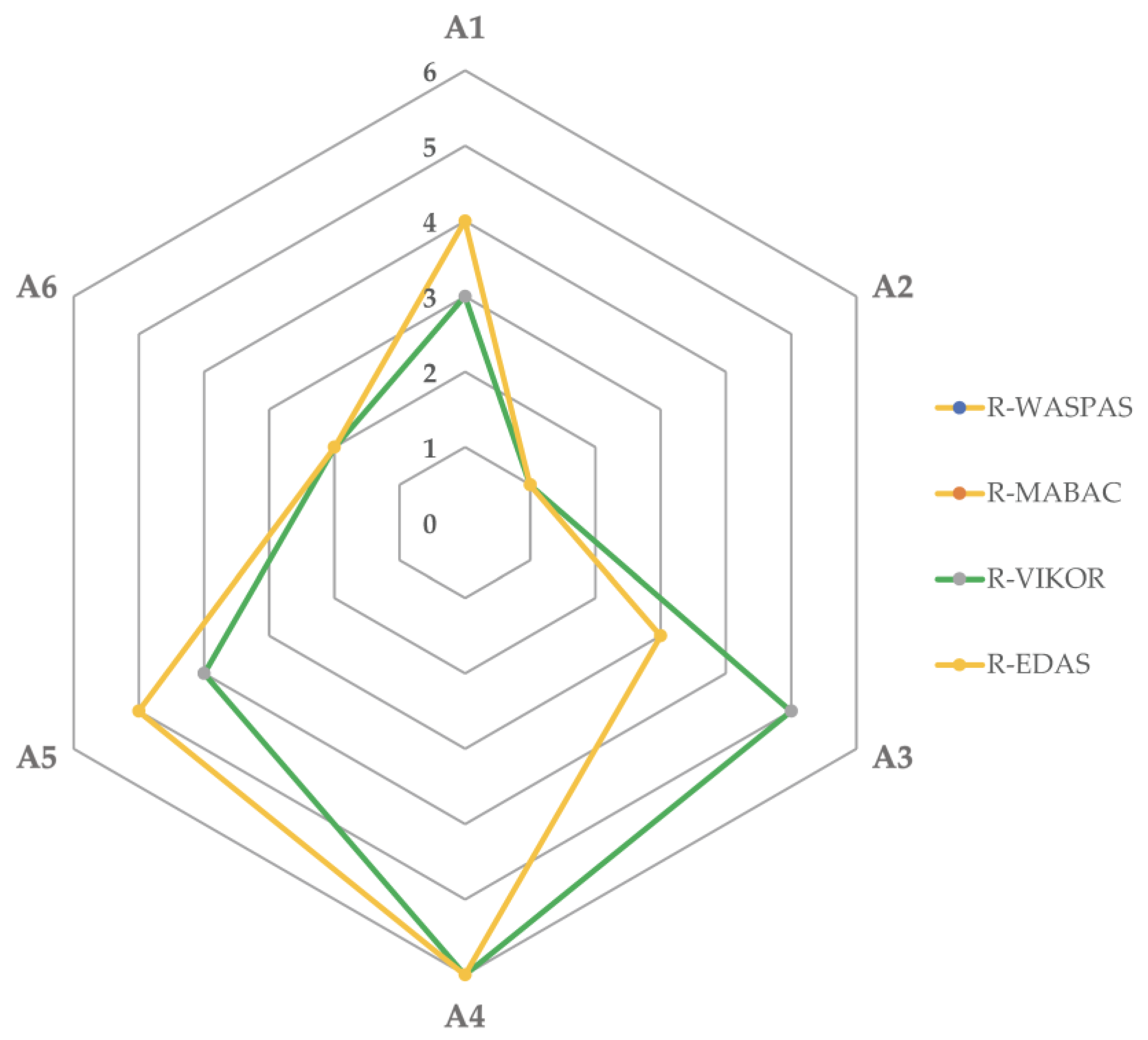
4.4. Results of the Comparative Analysis and Decision Making

In the literature, different MCDM techniques utilize diverse mathematical algorithms and operators to prioritize criteria or evaluate alternatives (e.g., AHP, TOPSIS etc.) [118,119]. In some instances, the results may thus differ depending on the MCDM approach employed, e.g., [89]. In a decision-making process, the purpose of a comparative analysis of different MCDM approaches is to assess the stability of the proposed MCDM approach’s results (i.e., the ranking order of the alternatives) [120]. The proposed approach is considered appropriate for a certain selection problem if the alternatives are ranked consistently by several MCDM approaches [121]. In this regard, the decision-making team can make an objective judgement based on consistent results. Therefore, prior to the decision-making, the results of the R-EDAS method were compared with three recently developed rough MCDM methods to verify the stability of the proposed approach, namely, the rough multi-attribute border approximation area comparison (R-MABAC) [81,84], the rough weighted aggregated sum product assessment (R-WASPAS) [31,75] and the rough VlseKriterijumska Optimizacija I Kompromisno Resenje (R-VIKOR) [78]. The results of the comparative analysis are shown in Figure 5. The stability of the rankings for the alternatives A2, A6, and A4 is unaffected by observing the results from the other methods. Moreover, the R-EDAS, R-WASPAS, and R-MABAC approaches provide identical results for all alternative rankings (i.e., A2 > A6 > A3 > A1 > A5 > A4). On the other hand, compared with other methods, the R-VIKOR method has a different ranking order for alternatives A1, A3, and A5. However, the rankings of the first-best choice (A2) and second-best choice (A6), as well as the ranking of A6, are the same compared with all the other methods. Consequently, alternative A2 (i.e., drop-head FWS for flat slabs and conventional FWS for beams) is the most appropriate FWS for this case study based on the proposed approach and the comparative analysis results. As a result of these findings, the decision-making team selected alternative A2 for the building construction project.

5. Discussion

The cost of the selected FWS may account for as much as 60% of the unit cost of the RC structure [64] and as much as 15% of the total construction cost [50]. In addition, up to 75% of the time spent on the construction of RC structures may be spent on formwork-related activities [101]. In this regard, formwork-related activities can be a substantial source of time waste [12] and material waste [44], which can affect the time and cost performance of the project. Therefore, selecting the FWS plays a crucial part in successfully completing an RC construction project [29]. In this study, an integrated approach was proposed to select the most appropriate FWS alternative for building construction projects, and it was used in a real-life case study. First, a decision-making team of five experts was formed, and the project-relevant FWS selection criteria and FWS alternatives were determined. Then, the R-AHP method was utilized to determine the rough-based criteria weights of the FWS selection criteria. According to the results of the R-AHP method, labour cost of the FWS (C14), labour productivity (C11), initial cost of the FWS (C1), speed of construction (C2), and labour quality (C16) were among the top five FWS selection criteria in the case study. This result is in accordance with Terzioglu et al.’s [52] study, in which the initial cost of the FWS and speed of construction were consistently ranked among the top five FWS selection criteria for the Turkish building construction sector based on the combined perception and perspectives of all respondent groups (e.g., engineer, contractor, and FWF). On the other hand, the relative importance level (i.e., the weight of the criteria) of other FWS selection criteria may vary depending on the type of project and the building structural design parameters (i.e., structural design-related criteria) [8,27]. For instance, the size of the building construction projects (e.g., the total area of building construction) significantly affects some FWS selection criteria, such as labour productivity [52]. Furthermore, depending on the type of the project and the structural design of the structure [122,123], labour productivity and labour cost of the FWS may be critical factors in building construction projects, particularly high-rise ones [22,124]. The weather conditions, such as high wind speeds, may also affect the labour productivity of formwork-related activities [125]. Consequently, in this case study, which could be regarded as a large-scale project (i.e., 20,000 m2 < 150,000 m2) [24] and consisted of three towers of high-rise building construction, where winds speeds may be high, labour productivity, and labour cost of the FWS were identified as critical FWS selection criteria.
Finally, using the criteria weights obtained from the R-AHP method, the R-EDAS method was utilized to compare the six alternatives based on 20 FWS selection criteria. In accordance with the results of the R-EDAS method and the comparative analysis, the decision-making team selected FWS alternative A2 (i.e., drop-head FWS for flat slabs and conventional FWS for beams), which was successfully implemented by the contractor in the building construction project. Based on the feedback from the contactor, the selected FWS both had a low floor cycle time (on average, eight days per floor (C2)) and a high degree of repetition (C3). The construction team was able to strip the FWS after 36 h of casting the concrete by using the drop-head feature of the FWS and back-propping the RC structure to ensure structural integrity. The assembly and disassembly activities of the FWS were performed by only three highly skilled workers (i.e., high labour quality (C16)), and crane time involvement (i.e., hoisting equipment (C8)) was decreased because the modular lightweight components of the FWS could be moved by hand. This was especially important at high wind speeds on the upper floors when the tower crane was inoperable. The initial cost of the FWS (C1) was high compared to most other FWS alternatives. On the other hand, since the selected FWS provided high labour productivity (C11) and low labour cost (C14) compared to others, the total cost for the FWS and its related activities was substantially reduced. In addition, the building construction project was completed within the planned project budget and schedule, while material and time waste were minimized by the selected FWS, further validating the effectiveness of the proposed approach. The proposed approach was recommended as an effective decision support tool for future FWS selection problems.

6. Conclusions and Recommendations

Since the selection of the appropriate FWS depends on compromising and conflicting criteria with a large number of FWS alternatives available, the majority of previous studies have focused on using MCDM methods (e.g., crisp AHP, crisp TOPSIS etc.) to select the appropriate FWS based on the perspectives of contractors or a particular group of construction professionals, e.g., [30,38,47]. However, the selection of the FWS is a group decision-making process in which different groups of construction professionals may perform FWS selection (e.g., company owners, project managers, construction managers, formwork design engineers etc.) [52]. In addition, the relative importance level of the FWS selection criteria and the selected FWS may vary depending on the perspectives and perceptions of these construction professionals [8]. Although previous studies considerably contribute to the existing body of knowledge on the FWS selection problem, the uncertainty, ambiguity, and subjectivity aspects of a group decision-making process [121,126] have mostly been neglected. The subjective judgments of the decision-makers, as well as the vagueness in the collected data from the experts, should be integrated into the MCDM method to improve the objectivity of the FWS selection process. As a result, the main objective of this study was to fill this critical knowledge gap. For this purpose, the proposed integrated approach used rough numbers combined with recently developed MCDM methods (i.e., R-AHP and R-EDAS) to overcome these issues [127]. In addition, the stability of the proposed approach was validated by comparing the results with the R-MABAC, R-WASPAS, and R-VIKOR methods. Finally, the proposed approach was implemented in a real-life case study in Turkey. The contractor’s and decision-making team’s response to project performance factors in the building construction project supported the usefulness of the proposed approach.
The proposed approach in this study is intended to be an important decision support tool for the FWS selection process in building construction projects. Mainly, it may be used to aggregate the perspectives of the engineer, the contractor and the FWF during the planning phase of the FWS since the early involvement of all stakeholders can improve the performance of the FWS supply chain [4]. Consequently, a building construction project’s time, cost, and quality performance may be improved by employing the proposed methodology in this study for the FWS selection problem.
This study has the following limitations:
  • The real-life case study in Section 4 is related to a residential building construction project in Turkey. Hence different results may be obtained if the proposed approach is applied to other types of construction projects in different countries.
  • The real-life case study in Section 4 was applied to only the selection of horizontal FWS. The selection of the vertical FWS may be performed using the proposed approach.
Based on the limitations of this study, the proposed MCDM approach for selecting the most appropriate FWS may be performed for different types of projects and in other countries to validate the results of this study. In addition, other rough MCDM methods can be employed using the methodology described in this study. Hence, in future studies, comparisons and validations with the results of this study should be made.

Author Contributions

Conceptualisation, T.T.; methodology, T.T.; software, T.T.; validation, T.T. and G.P.; formal analysis, T.T.; investigation, T.T.; resources, T.T.; data curation, T.T.; writing—original draft preparation, T.T.; writing—review and editing, G.P.; visualisation, T.T.; supervision, G.P. All authors have read and agreed to the published version of the manuscript.

Funding

This research received no external funding.

Institutional Review Board Statement

Not applicable.

Informed Consent Statement

The material presented in this study is the authors’ own original work, which has not been previously published elsewhere. The article is not currently being considered for publication elsewhere. The article reflects the authors’ own research and analysis in a truthful and complete manner. The article properly credits the meaningful contributions of co-authors and co-researchers. All sources used are properly disclosed. All authors have been personally and actively involved in substantial work leading to the paper, and will take public responsibility for its content.

Data Availability Statement

The data presented in this study are available on request from the corresponding author.

Conflicts of Interest

The authors declare no conflict of interest.

Appendix A

Table A1. Random consistency index (RI) [86].
m1617181920212223
RI15981609161816271634164116471653
Table A2. Individual pair-wise comparison matrices of the experts.
Expert 1 (CR1) = 0.044C1C2C3C4C5C6C7C8C9C10C11C12C13C14C15C16C17C18C19C20
C112325427361/2981412845
C21/21214317261/2671411835
C31/31/211/2221/24131/4441/411/41/2311
C41/21213417131/3661/221/21614
C51/51/41/21/3121/421/41/31/7221/61/21/6121/41/3
C61/41/31/21/41/211/22221/6221/611/61/341/21/2
C71/21214216141/3651/221/21512
C81/71/71/41/71/21/21/611/421/8111/81/21/81/611/51/5
C91/31/21141/214121/4441/311/41/241/41/5
C101/61/61/31/331/21/41/21/211/9111/71/31/71/221/41/5
C1122437638491991813934
C121/91/61/41/61/21/21/611/411/9111/91/31/81/71/21/41/4
C131/81/71/41/61/21/21/511/411/9111/91/31/81/71/21/41/4
C1411426628371991812822
C151/41/411/2211/22131/8331/811/41/4311
C1611426628471881411824
C171/21211316221/3771/2411724
C181/81/81/31/61/21/41/511/41/21/9221/81/31/81/711/51/5
C191/41/3114215441/3441/211/21/2511
C201/51/511/4321/25551/4441/211/41/4511
Expert 2 (CR2) = 0.097C1C2C3C4C5C6C7C8C9C10C11C12C13C14C15C16C17C18C19C20
C113434318271/4872321733
C21/31323226171/4682422844
C31/41/311/3231/33221/3331/511/31/6422
C41/31/2312328241/4771/331/32713
C51/41/31/21/2131/531/41/31/6331/51/31/6231/51/4
C61/31/21/31/31/3111111/6111/721/71/4311
C711/231/25115231/4541/311/22621
C81/81/61/31/81/311/511/531/6221/71/41/51/621/41/6
C91/211/21/2411/25131/3331/411/41/341/31/6
C101/71/71/21/4311/31/31/311/8221/71/41/71/331/41/6
C1144346646381882924845
C121/81/61/31/71/311/51/21/31/21/8121/81/41/61/71/21/31/3
C131/71/81/31/71/311/41/21/31/21/81/211/81/41/61/71/21/31/3
C141/21/2535737471/2881923933
C151/31/411/331/214141/9441/911/31/3422
C161/21/2336725471/2661/2312935
C1711/261/21/241/26331/4771/331/21835
C181/71/81/41/71/31/31/61/21/41/31/8221/91/41/91/811/41/4
C191/31/41/21511/24341/4331/31/21/31/3412
C201/31/41/21/34116661/5331/31/21/51/541/21
Expert 3 (CR3) = 0.067C1C2C3C4C5C6C7C8C9C10C11C12C13C14C15C16C17C18C19C20
C113215328361/3971413745
C21/31214318271/3781411745
C31/21/211/3221/34241/5441/411/41/2311
C411312517141/3661/331/31515
C51/51/41/21/2131/421/31/31/7321/51/21/6121/41/4
C61/31/31/21/51/311/33221/6231/611/61/451/31/2
C71/21314317121/4651/211/31512
C81/81/81/41/71/21/31/711/421/8111/71/21/71/611/51/5
C91/31/21/2131/214121/4331/311/41/341/41/6
C101/61/71/41/431/21/21/21/211/9221/61/41/71/231/41/5
C1133537648491881812743
C121/91/71/41/61/31/21/611/31/21/8121/81/31/81/71/21/31/3
C131/71/81/41/61/21/31/511/31/21/81/211/81/31/91/81/31/41/4
C1411435627361881812723
C151/41/411/32112141/8331/811/31/4412
C1611436637471891311835
C171/31211416321/2781/2411524
C181/71/71/31/51/21/51/511/41/31/7231/71/41/81/511/51/5
C191/41/4114315441/4341/211/31/2512
C201/51/511/5421/25651/3341/31/21/51/451/21
Expert 4 (CR4) = 0.065C1C2C3C4C5C6C7C8C9C10C11C12C13C14C15C16C17C18C19C20
C114315327361/4671423846
C21/41212325271/3781411744
C31/31/211/4221/34241/5441/411/41/2311
C411412517131/3661/331/32413
C51/51/21/21/2121/431/31/21/7321/51/21/6121/41/4
C61/31/31/21/51/211/33221/6221/611/41/451/31/2
C71/21/2314317131/4451/211/31312
C81/71/51/41/71/31/31/711/431/8111/71/21/71/711/51/5
C91/31/21/2131/214121/4331/321/41/341/41/6
C101/61/71/41/321/21/31/31/211/9221/61/41/71/231/41/5
C1143537648491871614734
C121/61/71/41/61/31/21/411/31/21/8121/81/31/81/71/21/31/3
C131/71/81/41/61/21/21/511/31/21/71/211/81/31/91/91/31/41/4
C1411435627361881912722
C151/41/411/321121/241/6331/911/31/4311
C161/21436437471891311824
C171/3121/21417321/4791/2411613
C181/81/71/31/41/21/51/311/41/31/7231/71/31/81/611/51/5
C191/41/4114315441/3341/211/21511
C201/61/411/3421/25651/4341/211/41/3511
Expert 5 (CR5) = 0.093C1C2C3C4C5C6C7C8C9C10C11C12C13C14C15C16C17C18C19C20
C111324528481/3652321533
C211233215461/4682422544
C31/31/211/3231/33221/3331/511/31/6422
C41/21/3312325241/4551/331/32913
C51/41/31/21/2131/531/41/31/9331/51/31/6231/51/4
C61/51/21/31/31/3111111/9111/721/71/4311
C71/2131/25115231/4741/311/21521
C81/81/51/31/51/311/511/531/6221/71/41/51/621/41/6
C91/41/41/21/2411/25131/3331/411/41/341/31/6
C101/81/61/21/4311/31/31/311/8221/71/41/71/331/41/6
C1134349946381892924945
C121/61/61/31/51/311/71/21/31/21/8121/81/41/61/71/21/31/3
C131/51/81/31/51/311/41/21/31/21/91/211/81/41/61/71/21/31/3
C141/21/2535737471/2881823933
C151/31/411/331/214141/9441/811/31/3422
C161/21/2336725471/2661/2312933
C1711/261/21/2416331/4771/331/21635
C181/51/51/41/91/31/31/51/21/41/31/9221/91/41/91/611/41/4
C191/31/41/21511/24341/4331/31/21/31/3412
C201/31/41/21/34116661/5331/31/21/31/541/21

References

  1. Safa, M.; Reinsma, S.; Haas, C.T.; Goodrum, P.M.; Caldas, C.H. A decision-making method for choosing concrete forming systems. Int. J. Constr. Manag. 2016, 18, 53–64. [Google Scholar] [CrossRef]
  2. Jarkas, A.M. Beamless or beam-supported building floors: Is buildability knowledge the missing link to improving productivity? Eng. Constr. Arch. Manag. 2017, 24, 537–552. [Google Scholar] [CrossRef]
  3. Nguyen, L.D.; Nguyen, H.T. Relationship between building floor and construction labor productivity: A case of structural work. Eng. Constr. Arch. Manag. 2013, 20, 563–575. [Google Scholar] [CrossRef]
  4. Terzioglu, T.; Polat, G.; Turkoglu, H. Analysis of industrial formwork systems supply chain using value stream mapping. J. Eng. Proj. Prod. Manag. 2022, 12, 47–61. [Google Scholar] [CrossRef]
  5. Kim, K.; Teizer, J. Automatic design and planning of scaffolding systems using building information modelling. Adv. Eng. Inform. 2014, 28, 66–80. [Google Scholar] [CrossRef]
  6. Kim, K.; Cho, Y.; Zhang, S. Integrating work sequences and temporary structures into safety planning: Automated scaffolding-related safety hazard identification and prevention in BIM. Autom. Constr. 2016, 70, 128–142. [Google Scholar] [CrossRef]
  7. Lee, B.; Choi, H.; Min, B.; Ryu, J.; Lee, D.E. Development of formwork automation design software for improving construction productivity. Autom. Constr. 2021, 126, 103680. [Google Scholar] [CrossRef]
  8. Terzioglu, T.; Polat, G.; Turkoglu, H. Formwork System Selection Criteria for Building Construction Projects: A Structural Equation Modelling Approach. Buildings 2022, 12, 204. [Google Scholar] [CrossRef]
  9. Hurd, M.K. Formwork for Concrete, 7th ed.; ACI (American Concrete Institute): Farmington Hills, MI, USA, 2005. [Google Scholar]
  10. Shin, Y.; Kim, T.; Cho, H.H.; Kang, K.I. A formwork method selection model based on boosted decision trees in tall building construction. Autom. Constr. 2012, 23, 47–54. [Google Scholar] [CrossRef]
  11. Lee, C.; Ham, S. Automated system for form layout to increase the proportion of standard forms and improve work efficiency. Autom. Constr. 2018, 87, 273–286. [Google Scholar] [CrossRef]
  12. Ko, C.H.; Kuo, J.D. Making formwork construction lean. J. Civ. Eng. Manag. 2015, 21, 444–458. [Google Scholar] [CrossRef]
  13. Kannan, M.; Santhi, M. Automated constructability rating framework for concrete formwork systems using building information modeling. Asian J. Civ. Eng. 2018, 19, 387–413. [Google Scholar] [CrossRef]
  14. Rosenbaum, S.; Toledo, M.; Gonzalez, V. Improving environmental and production performance in construction projects using value-stream mapping: Case study. J. Constr. Eng. Manag. 2014, 140, 1–11. [Google Scholar] [CrossRef]
  15. Vilventhan, A.; Ram, V.; Sugumaran, S. Value stream mapping for identification and assessment of material waste in construction: A case study. Waste Manag. Res. 2019, 37, 815–825. [Google Scholar] [CrossRef] [PubMed]
  16. Spitz, N.; Coniglio, N.; Libessart, L.; El Mansori, M.; Djelal, C. Characterizing tribological behavior of fresh concretagainst formwork surfaces. Constr. Build. Mater. 2021, 303, 124233. [Google Scholar] [CrossRef]
  17. Fischer, M.; Tatum, C.B. Characteristics of design-relevant constructability knowledge. J. Constr. Eng. Manag. 1997, 123, 253–260. [Google Scholar] [CrossRef]
  18. Peurifoy, R.L.; Oberlender, G.D. Formwork for Concrete Structures; McGraw-Hill Professional Publishing: New York, NY, USA, 1996. [Google Scholar]
  19. Jiang, L.; Leicht, R.M.; Kremer, G.E.O. Eliciting constructability knowledge for BIM-enabled automated, rule-based constructability review: A case study of formwork. In Proceedings of the 2014 Construction Research Congress, Atlanta, GA, USA, 19–21 May 2014. [Google Scholar] [CrossRef] [Green Version]
  20. Hallowell, M.R.; Gambatese, J.A. Activity-based safety risk quantification for concrete formwork construction. J. Constr. Eng. Manag. 2009, 135, 990–998. [Google Scholar] [CrossRef]
  21. Lee, J.; Cho, J. An inference method of safety accidents of construction workers according to the risk factor reduction of the Bayesian network model in linear scheduling. Int. J. Manag. 2020, 11, 1–12. [Google Scholar]
  22. Zayed, T.; Mohamed, E. A case of productivity model for automatic climbing system. Eng. Constr. Arch. Manag. 2014, 21, 33–50. [Google Scholar] [CrossRef]
  23. Jarkas, A.M. The impacts of buildability factors on formwork labour productivity of columns. J. Civ. Eng. Manag. 2010, 16, 471–483. [Google Scholar] [CrossRef]
  24. Hanna, A.S. Concrete Formwork Systems; Marcel Dekker: New York, NY, USA, 1999. [Google Scholar]
  25. Biruk, S.; Jaskowski, P. Optimization of vertical formwork layout plans using mixed integer linear programming. Int. J. Civ. Eng. 2017, 15, 125–133. [Google Scholar] [CrossRef] [Green Version]
  26. Hanna, A.S.; Willenbrock, J.H.; Sanvido, V.E. Knowledge acquisition and development for formwork selection system. J. Constr. Eng. Manag. 1992, 118, 179–198. [Google Scholar] [CrossRef]
  27. Terzioglu, T.; Turkoglu, H.; Polat, G. Formwork systems selection criteria for building construction projects: A critical review of the literature. Can. J. Civ. Eng. 2022, 49, 617–626. [Google Scholar] [CrossRef]
  28. Darwish, M.; Elsayed, A.Y.; Nassar, K. Design and constructability of a novel funicular arched steel truss falsework. J. Constr. Eng. Manag. 2018, 144, 04018002. [Google Scholar] [CrossRef]
  29. Elbeltagi, E.; Hosny, O.; Elhakeem, A.; Abd-Elrazek, M.; El-Abbasy, M. Fuzzy logic model for selection of vertical formwork systems. J. Constr. Eng. Manag. 2012, 138, 832–840. [Google Scholar] [CrossRef]
  30. Hansen, S.; Siregar, P.H.R.; Jevica, J. AHP-based decision-making framework for formwork system selection by contractors. J. Constr. Dev. Count. 2020, 25, 235–255. [Google Scholar] [CrossRef]
  31. Stojić, G.; Stević, Ž.; Antuchevičienė, J.; Pamučar, D.; Vasiljević, M. A novel rough WASPAS approach for supplier selection in a company manufacturing PVC carpentry products. Information 2018, 9, 121. [Google Scholar] [CrossRef] [Green Version]
  32. Menekşe, A.; Akdağ, H.C. Distance education tool selection using novel spherical fuzzy AHP EDAS. Soft Comput. 2022, 26, 1617–1635. [Google Scholar] [CrossRef]
  33. Stević, Z.; Vasiljević, M.; Puška, A.; Tanackov, I.; Junevičius, R.; Vesković, S. Evaluation of suppliers under uncertainty: A multiphase approach based on fuzzy AHP and fuzzy EDAS. Transport 2019, 34, 52–66. [Google Scholar] [CrossRef] [Green Version]
  34. Karatop, B.; Taşkan, B.; Adar, E.; Kubat, C. Decision analysis related to the renewable energy investments in Turkey based on a fuzzy AHP-EDAS-fuzzy FMEA approach. Comput. Ind. Eng. 2021, 151, 106958. [Google Scholar] [CrossRef]
  35. Toan, P.N.; Dang, T.-T.; Hong, L.T.T. Evaluating Video Conferencing Software for Remote Working Using Two-Stage Grey MCDM: A Case Study from Vietnam. Mathematics 2022, 10, 946. [Google Scholar] [CrossRef]
  36. Huang, R.Y.; Chen, J.J.; Sun, K.S. Planning gang formwork operations for building construction using simulations. Autom. Constr. 2004, 13, 765–779. [Google Scholar] [CrossRef]
  37. Hanna, A.S. An Interactive Knowledge-Based Formwork Selection System for Buildings. Ph.D. Dissertation, Department of Civil Engineering, Pennsylvania State University, State College, PA, USA, 1989. [Google Scholar]
  38. Basu, R.; Jha, K.N. An AHP based model for the selection of horizontal formwork systems in Indian residential construction. Int. J. Struct. Civ. Eng. Res. 2016, 5, 80–86. [Google Scholar] [CrossRef]
  39. Hanna, A.S.; Sanvido, V.E. Interactive vertical formwork selection system. Concr. Int. 1990, 12, 26–32. [Google Scholar]
  40. Kamarthi, S.V.; Sanvido, V.E.; Kumara, S.R.T. Neuroform—neural network system for vertical formwork selection. J. Comp. Civ. Eng. 1992, 6, 178–199. [Google Scholar] [CrossRef]
  41. Hanna, A.S.; Senouci, A.B. NEUROSLAB- neural network system for horizontal formwork selection. Can. J. Civ. Eng. 1995, 22, 785–792. [Google Scholar] [CrossRef]
  42. Abdel-Razek, M.E. Formwork selection systems in building construction. J. Eng. Appl. Sci. Cairo Univ. 1999, 46, 629–644. [Google Scholar]
  43. Elazouni, A.; Ali, A.; Abdel-Razek, R. Estimating the acceptability of new formwork systems using neural networks. J. Constr. Eng. Manag. 2005, 131, 33–41. [Google Scholar] [CrossRef]
  44. Tam, C.M.; Tong, T.K.L.; Lau, T.C.T.; Chan, K.K. Selection of vertical formwork system by probabilistic neural networks models. Constr. Manag. Econ. 2005, 23, 245–254. [Google Scholar] [CrossRef]
  45. Shin, Y. Formwork system selection model for tall building construction using the Adaboost algorithm. J. Korea Inst. Build. Constr. 2011, 11, 523–529. [Google Scholar] [CrossRef]
  46. Elbeltagi, E.; Hosny, O.; Elhakeem, A.; Abd-Elrazek, M.; Abdullah, A. Selection of slab formwork system using fuzzy logic. Constr. Manag. Econ. 2011, 29, 659–670. [Google Scholar] [CrossRef]
  47. Krawczyńska-Piechna, A. Application of TOPSIS method in formwork selection problem. Appl. Mech. Mat. 2015, 797, 101–107. [Google Scholar] [CrossRef]
  48. Martinez, E.; Tommelein, I.D.; Alvear, A. Formwork system selection using choosing by advantages. In Proceedings of the Construction Research Congress 2016, San Juan, Puerto Rico, 31 May–2 June 2016; pp. 1700–1709. [Google Scholar] [CrossRef]
  49. Teja, G.S.; Hanagodimath, A.V.; Naik, S.K. Fuzzy logic model for selection of concrete placement methods and formwork systems. In Proceedings of the 3rd International Conference on Construction, Real Estate, Infrastructure and Project Management, National Institute of Construction Management and Research, Pune, India, 23–25 November 2018; pp. 89–98. [Google Scholar]
  50. Ko, C.H.; Wang, W.; Kuo, J.D. Improving formwork engineering using the Toyota way. J. Eng. Proj. Prod. Manag. 2011, 1, 13–27. [Google Scholar] [CrossRef]
  51. Ko, C.H.; Kuo, J.D. Making formwork design lean. J. Eng. Proj. Prod. Manag. 2019, 9, 29–47. [Google Scholar] [CrossRef] [Green Version]
  52. Terzioglu, T.; Polat, G.; Turkoglu, H. Analysis of formwork system selection criteria for building construction projects: A comparative study. Buildings 2021, 11, 618. [Google Scholar] [CrossRef]
  53. Dikshit-Ratnaparkhi, A.; Bormane, D.; Ghongade, R. A novel entropy-based weighted attribute selection in enhanced multicriteria decision-making using fuzzy TOPSIS model for hesitant fuzzy rough environment. Complex Intell. Syst. 2021, 7, 1785–1796. [Google Scholar] [CrossRef]
  54. Li, X.; Yu, S.; Chu, J. Optimal selection of manufacturing services in cloud manufacturing: A novel hybrid MCDM approach based on rough ANP and rough TOPSIS. J. Intell. Fuzzy Syst. 2018, 34, 4041–4056. [Google Scholar] [CrossRef]
  55. Qi, J.; Hu, J.; Peng, Y.H. Integrated rough VIKOR for customer-involved design concept evaluation combining with customers’ prefrences and designers’ perceptions. Adv. Eng. Inform. 2020, 46, 101138. [Google Scholar] [CrossRef]
  56. Banihashemi, S.A.; Khalilzadeh, M.; Antucheviciene, J.; Šaparauskas, J. Trading off time–cost–quality in construction project scheduling problems with Fuzzy SWARA–TOPSIS approach. Buildings 2021, 11, 387. [Google Scholar] [CrossRef]
  57. Liang, R.; Li, R.; Yan, X.; Xue, Z.; Wei, X. Evaluating and selecting the supplier in prefabricated megaprojects using extended fuzzy TOPSIS under hesitant environment: A case study from China. Eng. Constr. Arch. Manag. 2022. [Google Scholar] [CrossRef]
  58. Eghbali-Zarch, M.; Tavakkoli-Moghaddam, R.; Dehghan-Sanej, K.; Kaboli, A. Prioritizing the effective strategies for construction and demolition waste management using fuzzy IDOCRIW and WASPAS methods. Eng. Constr. Arch. Manag. 2022, 29, 1109–1138. [Google Scholar] [CrossRef]
  59. Mohammadnazari, Z.; Mousapour Mamoudan, M.; Alipour-Vaezi, M.; Aghsami, A.; Jolai, F.; Yazdani, M. Prioritizing post-disaster reconstruction projects using an integrated multi-criteria decision-making approach: A case study. Buildings 2022, 12, 136. [Google Scholar] [CrossRef]
  60. Issa, U.; Saeed, F.; Miky, Y.; Alqurashi, M.; Osman, E. Hybrid AHP-Fuzzy TOPSIS approach for selecting deep excavation support system. Buildings 2022, 12, 295. [Google Scholar] [CrossRef]
  61. Rajeshkumar, V.; Anandaraj, S.; Kavinkumar, V.; Elango, K.S. Analysis of factors influencing formwork material selection in construction buildings. Mater. Today Proc. 2021, 37, 880–885. [Google Scholar] [CrossRef]
  62. Lohana, Y. Analysis of productivity criteria for selection of formwork system for construction of high rise building mega projects. In Proceedings of the 3rd International Conference on Construction, Real Estate, Infrastructure and Project Management, National Institute of Construction Management and Research, Pune, India, 23–25 November 2018; pp. 140–154. [Google Scholar]
  63. Krawczyńska-Piechna, A. An analysis of the decisive criteria in formwork selection problem. Arch. Civ. Eng. 2016, 62, 185–196. [Google Scholar] [CrossRef] [Green Version]
  64. Krawczyńska-Piechna, A. Comprehensive approach to efficient planning of formwork utilisation on the construction site. Procedia Eng. 2017, 182, 366–372. [Google Scholar] [CrossRef]
  65. ACI (American Concrete Institute). Guide to Formwork for Concrete; ACI 347-304; ACI: Farmington Hills, MI, USA, 2004. [Google Scholar]
  66. ACI (American Concrete Institute). Guide to Curing Concrete; ACI 308R-01; ACI: Farmington Hills, MI, USA, 2008. [Google Scholar]
  67. Abou Ibrahim, H.A.; Hamzeh, F.R. Expected lean effects of advanced high-rise formwork systems. In Proceedings of the 23rd Annual Conference of the International Group for Lean Construction, Perth, Australia, 29–31 July 2015; pp. 83–92. [Google Scholar] [CrossRef]
  68. Jiang, L.; Leicht, R.M. Automated rule-based constructability checking: Case study of formwork. J. Manag. Eng. 2015, 31, A4014004. [Google Scholar] [CrossRef]
  69. Miszewska, E.; Niedostatkiewicz, M.; Wiśniewski, R. The selection of anchoring system for floating houses by means of AHP method. Buildings 2020, 10, 75. [Google Scholar] [CrossRef] [Green Version]
  70. Xu, C.; Wu, Y.; Dai, S. What are the critical barriers to the development of hydrogen refueling stations in China? A modified fuzzy DEMATEL approach. Energy Policy 2020, 142, 111495. [Google Scholar] [CrossRef]
  71. Wu, Y.; Xu, C.; Zhang, T. Evaluation of renewable power sources using a fuzzy MCDM based on cumulative prospect theory: A case in China. Energy 2018, 147, 1227–1239. [Google Scholar] [CrossRef]
  72. Pawlak, Z. Rough sets. Int. J. Comput. Inf. Sci. 1982, 11, 341–356. [Google Scholar] [CrossRef]
  73. Akbari, S.; Khanzadi, M.; Gholamian, M.R. Building a rough sets-based prediction model for classifying large-scale construction projects based on sustainable success index. Eng. Constr. Arch. Manag. 2018, 25, 534–558. [Google Scholar] [CrossRef] [Green Version]
  74. Zhai, L.Y.; Khoo, L.P.; Zhong, Z.W. A rough set based QFD approach to the management of imprecise design information in product development. Adv. Eng. Inf. 2009, 23, 222–228. [Google Scholar] [CrossRef]
  75. Pavlovskis, M.; Migilinskas, D.; Antucheviciene, J.; Kutut, V. Ranking of heritage building conversion alternatives by applying BIM and MCDM: A case of Sapieha Palace in Vilnius. Symmetry 2019, 11, 973. [Google Scholar] [CrossRef] [Green Version]
  76. Matić, B.; Jovanović, S.; Marinković, M.; Sremac, S.; Kumar Das, D.; Stević, Ž. A Novel integrated interval rough MCDM model for ranking and selection of asphalt production plants. Mathematics 2021, 9, 269. [Google Scholar] [CrossRef]
  77. Khoo, L.-P.; Zhai, L.-Y. A prototype genetic algorithm enhanced rough set-based rule induction system. Comput. Ind. 2001, 46, 95–106. [Google Scholar] [CrossRef]
  78. Zhu, G.N.; Hu, J.; Qi, J.; Gu, C.C.; Peng, J.H. An integrated AHP and VIKOR for design concept evaluation based on rough number. Adv. Eng. Inf. 2015, 29, 408–418. [Google Scholar] [CrossRef]
  79. Del Giudice, V.; De Paola, P.; Cantisani, G.B. Rough set theory for real estate appraisals: An application to directional district of Naples. Buildings 2017, 7, 12. [Google Scholar] [CrossRef]
  80. Stević, Ž.; Pamučar, D.; Kazimieras Zavadskas, E.; Ćirović, G.; Prentkovskis, O. The selection of wagons for the internal transport of a logistics company: A novel approach based on rough BWM and rough SAW methods. Symmetry 2017, 9, 264. [Google Scholar] [CrossRef] [Green Version]
  81. Chakraborty, S.; Dandge, S.S.; Agarwal, S. Non-traditional machining processes selection and evaluation: A rough multi-attributive border approximation area comparison approach. Comput. Ind. Eng. 2020, 149, 106201. [Google Scholar] [CrossRef]
  82. Beiki Ashkezari, A.; Zokaee, M.; Aghsami, A.; Jolai, F.; Yazdani, M. Selecting an appropriate configuration in a construction project using a hybrid multiple attribute decision making and failure analysis methods. Buildings 2022, 12, 643. [Google Scholar] [CrossRef]
  83. Li, K.; Duan, T.; Li, Z.; Xiahou, X.; Zeng, N.; Li, Q. Development path of construction industry internet platform: An AHP–TOPSIS integrated approach. Buildings 2022, 12, 441. [Google Scholar] [CrossRef]
  84. Roy, J.; Chatterjee, K.; Bandyopadhyay, A.; Kar, S. Evaluation and selection of medical tourism sites: A rough analytic hierarchy process based multi-attributive border approximation area comparison approach. Expert Syst. 2017, 35, e12232. [Google Scholar] [CrossRef] [Green Version]
  85. Saaty, R.W. The Analytic Hierarchy Process—What it is and how it is used. Math. Model. 1987, 9, 161–176. [Google Scholar] [CrossRef] [Green Version]
  86. Alonso, J.A.; Lamata, T. Consistency in the analytic hierarchy process: A new approach. Int. J. Uncertain. Fuzziness Knowl.-Based Syst. 2006, 14, 445–459. [Google Scholar] [CrossRef] [Green Version]
  87. Kang, D.; Park, Y. Review-based measurement of customer satisfaction in mobile service: Sentiment analysis and VIKOR approach. Expert Syst. Appl. 2014, 41, 1041–1050. [Google Scholar] [CrossRef]
  88. Keshavarz Ghorabaee, M.; Zavadskas, E.K.; Olfat, L.; Turskis, Z. Multi-Criteria inventory classification using a new method of evaluation based on distance from average solution (EDAS). Informatica 2015, 26, 435–451. [Google Scholar] [CrossRef]
  89. Stević, Ž.; Pamučar, D.; Vasiljević, M.; Stojić, G.; Korica, S. Novel integrated multi-criteria model for supplier selection: Case study construction company. Symmetry 2017, 9, 279. [Google Scholar] [CrossRef] [Green Version]
  90. Turskis, Z.; Juodagalvienie, B. A novel hybrid multi-criteria decision-making model to assess a stairs shape for dwelling houses. J. Civ. Eng. Manag. 2016, 22, 1078–1087. [Google Scholar] [CrossRef] [Green Version]
  91. Keshavarz Ghorabaee, M.; Amiri, M.; Olfat, L.; Khatami Firouzabadi, S.A. Designing a multi-product multi-period supply chain network with reverse logistics and multiple objectives under uncertainty. Technol. Econ. Dev. Econ. 2017, 23, 520–548. [Google Scholar] [CrossRef] [Green Version]
  92. Kahraman, C.; Keshavarz Ghorabaee, M.; Zavadskas, E.K.; Cevik Onar, S.; Yazdani, M.; Oztaysi, B. Intuitionistic fuzzy EDAS method: An application to solid waste disposal site selection. J. Environ. Eng. Landsc. Manag. 2017, 25, 1–12. [Google Scholar] [CrossRef]
  93. Peng, X.; Liu, C. Algorithms for neutrosophic soft decision making based on EDAS, new similarity measure and level soft set. J. Intell. Fuzzy Syst. 2017, 32, 955–968. [Google Scholar] [CrossRef] [Green Version]
  94. Zavadskas, E.K.; Cavallaro, F.; Podvezko, V.; Ubarte, I.; Kaklauskas, A. MCDM assessment of a healthy and safe built environment according to sustainable development principles: A practical neighborhood approach in Vilnius. Sustainability 2017, 9, 702. [Google Scholar] [CrossRef] [Green Version]
  95. Ecer, F. Third-party logistics (3Pls) provider selection via Fuzzy AHP and EDAS integrated model. Technol. Econ. Dev. Econ. 2018, 24, 615–634. [Google Scholar] [CrossRef]
  96. Pamucar, D.; Mihajlovic, M.; Obradovic, R.; Atanaskovic, P. Novel approach to group multi-criteria decision making based on interval rough numbers: Hybrid DEMATEL-ANP-MAIRCA model. Expert Syst. Appl. 2017, 88, 58–80. [Google Scholar] [CrossRef] [Green Version]
  97. Matić, B.; Jovanović, S.; Das, D.K.; Zavadskas, E.K.; Stević, Ž.; Sremac, S.; Marinković, M. A new hybrid MCDM model: Sustainable supplier selection in a construction company. Symmetry 2019, 11, 353. [Google Scholar] [CrossRef] [Green Version]
  98. Gnida, J. Formwork for high-rise construction. In Proceedings of the CTBUH Word Conference 2010, Mumbai, India, 3 February 2010. [Google Scholar]
  99. Kim, T.; Lim, H.; Lee, U.K.; Cha, M.; Cho, H.; Kang, K.I. Advanced formwork method integrated with a layout planning model for tall building construction. Can. J. Civ. Eng. 2012, 39, 1173–1183. [Google Scholar] [CrossRef]
  100. Al-Tabtabai, H.M. Genetic algorithm optimal model for slab formwork cost and design. Eng. J. Univ. Qatar 2000, 13, 177–192. [Google Scholar]
  101. Jha, K.N. Formwork for Concrete Structures; Tata McGraw-Hill: New Delhi, India, 2012. [Google Scholar]
  102. Jha, J.; Sinha, S.K. Modern Practices in Formwork for Civil Engineering Construction Works; University Science Press: Sausalito, CA, USA, 2014. [Google Scholar]
  103. Shrivastava, A.; Chourasia, D.; Saxena, S. Planning of formwork materials. Mater. Today Proc. 2021, 47, 7060–7063. [Google Scholar] [CrossRef]
  104. Pawar, S.P.; Atterde, P.M. Comparative analysis of formwork in multistory building. Int. J. Res. Eng. Technol. 2014, 3, 22–24. [Google Scholar]
  105. Radziejowska, A.; Sobotka, A. Comparative analysis of slab formwork of monolithic reinforced concrete buildings. Arch. Civ. Eng. 2020, 66, 127–141. [Google Scholar] [CrossRef]
  106. Karke, S.M.; Kumathekar, M.B. Comparison of the use of traditional and modern formwork systems. In Civil Engineering Systems and Sustainable Innovations; Excellent Publishing House: New Delhi, India, 2014; pp. 348–355. [Google Scholar]
  107. Pawar, A.D.; Rajput, B.L.; Agarwal, A.L. Factors affecting selection of concrete structure formwork. In Proceedings of the 3rd International Conference on Construction, Real Estate, Infrastructure and Project Management, National Institute of Construction Management and Research, Pune, India, 23–25 November 2018; pp. 45–52. [Google Scholar]
  108. Terzioglu, T.; Polat, G.; Turkoglu, H. Traditional vs. industrial formwork system supply chains. In Proceedings of the International Civil Engineering and Architecture Conference (ICEARC’19), Trabzon, Turkey, 17–20 April 2019; pp. 87–97. [Google Scholar]
  109. Ray, P.; Bera, D.K.; Rath, A.K. Comparison between the tunnel form system formwork and the MIVAN formwork system in a multi-unit building project. In Recent Developments in Sustainable Infrastructure; Das, B., Barbhuiya, S., Gupta, R., Saha, P., Eds.; Lecture Notes in Civil Engineering; Springer: Singapore; Volume 75, pp. 891–908. [CrossRef]
  110. Dilek, Y.; Karasin, A. Examination of structures built with tunnel formwork in terms of strength and cost according to the earthquake regulations of 2007 and 2018. Adv. Civ. Eng. 2021, 2021, 1–19. [Google Scholar] [CrossRef]
  111. Deshmukh, A.S.; Shalgar, M.A. Study of tunnel formwork vs. aluminum formwork. Int. J. Res. Eng. Technol. 2016, 3, 477–480. [Google Scholar]
  112. Aradhye, T.D.; Apte, M.R. Study of advanced tunnel formwork system in high rise building. Int. J. Res. Eng. Technol. 2016, 5, 529–533. [Google Scholar]
  113. Chaudhary, A.D. Study of tunnel formwork system and comparative analysis with conventional formwork. Int. J. Sci. Eng. Res. 2017, 8, 1281–1286. [Google Scholar] [CrossRef]
  114. Prajapati, R.; Pitroda, J.; Bhavsar, J.J. Plastic formwork: New era for construction sector. In Proceedings of the National Conference on: Trends and Challenges in Today’s Transforming World, Civil Engineering Department S.N.P.I.T. & R.C., Umrakh, India, 29 March 2014. [Google Scholar]
  115. Ghazali, M.A.A.; Bahardin, N.F.; Zaidi, M.A. Literature mapping: Critical factors in industrialized building system plastic formwork application. Int. Rev. Manag. Mark. 2016, 6, 204–208. [Google Scholar]
  116. Das, R.; Bhattacharya, I.; Saha, R. Comparative study between different types of formwork. Int. Res. J. Adv. Eng. Sci. 2016, 1, 173–175. [Google Scholar]
  117. Sohoni, P.; Ghaffar, A.; Matsagar, V.A.; Jha, K.N. Optimization of shoring/reshoring levels in high-rise building construction. Organ. Technol. Manag. Constr. 2018, 10, 1803–1826. [Google Scholar] [CrossRef] [Green Version]
  118. Zavadskas, E.K.; Turskis, Z. Multiple criteria decision making (MCDM) methods in economics: An overview. Technol. Econ. Dev. Econ. 2011, 17, 397–427. [Google Scholar] [CrossRef] [Green Version]
  119. Xu, C.; Ke, Y.; Li, Y.; Chu, H.; Wu, Y. Data-driven configuration optimization of an off-grid wind/PV/hydrogen system based on modified NSGA-II and CRITIC-TOPSIS. Energy Conv. Manag. 2020, 215, 112892. [Google Scholar] [CrossRef]
  120. Hashemi, H.; Mousavi, S.M.; Zavadskas, E.K.; Chalekaee, A.; Turskis, Z. A New Group Decision Model Based on Grey-Intuitionistic Fuzzy-ELECTRE and VIKOR for Contractor Assessment Problem. Sustainability 2018, 10, 1635. [Google Scholar] [CrossRef] [Green Version]
  121. Riaz, M.; Hashmi, M.R.; Kalsoom, H.; Pamucar, D.; Chu, Y.-M. Linear Diophantine Fuzzy Soft Rough Sets for the Selection of Sustainable Material Handling Equipment. Symmetry 2020, 12, 1215. [Google Scholar] [CrossRef]
  122. Dikmen, S.U.; Sonmez, M. An artificial neural networks model for estimation of formwork labour. J. Civ. Eng. Manag. 2011, 17, 340–347. [Google Scholar] [CrossRef]
  123. Jarkas, A.M. Buildability factors affecting formwork labour productivity of building floors. Can. J. Civ. Eng. 2010, 37, 1383–1394. [Google Scholar] [CrossRef]
  124. Lee, D.; Lim, H.; Kim, T.; Cho, H.; Kang, K. Advanced planning model of formwork layout for productivity improvement in high-rise building construction. Autom. Constr. 2018, 85, 232–240. [Google Scholar] [CrossRef]
  125. Malara, J.; Plebankiewicz, E.; Juszczyk, M. Formula for determining the construction workers productivity including environmental factors. Buildings 2019, 9, 240. [Google Scholar] [CrossRef] [Green Version]
  126. Zhang, J.; Yang, D.; Li, Q.; Lev, B.; Ma, Y. Research on Sustainable Supplier Selection Based on the Rough DEMATEL and FVIKOR Methods. Sustainability 2021, 13, 88. [Google Scholar] [CrossRef]
  127. Shojaei, P.; Bolvardizadeh, A. Rough MCDM model for green supplier selection in Iran: A case of university construction project. Built Environ. Proj. Asset Manag. 2020, 10, 437–452. [Google Scholar] [CrossRef]
Figure 1. Research methodology flowchart of the proposed approach.
Buildings 12 01084 g001
Figure 2. The general structure of the decision hierarchy.
Buildings 12 01084 g002
Figure 3. The basic concept of rough set theory.
Buildings 12 01084 g003
Figure 4. Final decision hierarchy for the case study.
Buildings 12 01084 g004
Figure 5. Comparative analysis of proposed approach with other rough MCDM methods.
Buildings 12 01084 g005
Table 1. FWS selection criteria for building construction projects, adapted from Refs. [27,52].
FWS Selection CriteriaDescriptionReferences
Compatibility with type of structural slabThe degree of compatibility of the FWS with the type of the structural slab (e.g., flat plate, two-way slab with beams etc.)[10,26]
Compatibility with type of structural lateral loads-supporting systemThe degree of compatibility of the FWS with the type of the structural lateral loads-supporting system (e.g., shear wall, bearing wall etc.)[40,44]
Total building heightThe degree of effectiveness of the FWS based on the total building height (i.e., low, mid, or high-rise building)[10,45]
Compatibility with variation in column/wall dimensions and locationThe degree of compatibility of the FWS with the variation in column/wall dimensions and location[24,39]
Compatibility with variation in openings/inserts dimensions and locationThe degree of compatibility of the FWS with variation in openings/inserts dimensions and location in the RC structure[24,39]
Degree of repetition of the FWSHigh degree of repetition means the FWS can complete repetitive floor cycles without any damage or modification to the FWS itself[1,38]
Number of floorsThe degree of effectiveness of the FWS based on the total number of floors[10,61]
Floor areaThe degree of effectiveness of the FWS based on the floor area[10,61]
Floor to floor heightThe degree of effectiveness of the FWS based on the floor-to-floor height[29]
Compatibility with uniformity of buildingThe degree of compatibility of the FWS with changing layouts within the building[29]
Type of concrete finishThe degree of surface quality of the finished concrete after the FWS has been removed[39]
Speed of constructionFloor cycle time of the FWS (i.e., erecting, stripping, and moving time of the FWS) calculated as days/floor[1,62]
Labour qualityThe degree of labour quality required to utilize the FWS (e.g., skilled, or unskilled laborers)[26,46]
Labour productivityThe total area of the FWS erected/dismantled (m2) divided by the labour input (man-hours) calculated as m2/man-hour[49,61]
Weather conditionsVariables such as hot and cold outdoor temperatures or local wind speeds which may affect the FWS selection[38]
Site accessThe availability of adequate site access required by the FWS[24,39]
Size of siteThe availability of adequate size of site required by the FWS for assembly and/or disassembly processes[38]
Initial cost of the FWSThe cost of purchasing or renting the FWS calculated as cost/m2[1,46]
Transportation cost of the FWSThe cost of transporting the FWS to the job site and returning the FWS to the desired location for storage calculated as cost/m2[61]
Maintenance cost of the FWSThe cost of maintaining the FWS (e.g., cleaning, repairing, and storing) calculated as cost/m2[52]
Labour cost of the FWSThe cost of striking, stripping and handling of the FWS calculated as cost/m2[1,46]
Potential reuse of the FWS in other projectsThe degree of potential reuse of the FWS in other projects[38]
Hoisting equipmentThe degree of crane time involvement required by the FWS[24,26]
In-house capabilityThe degree of experience with the FWS [41,63]
FWS sustainabilityThe type of material used, potential of recycling, carbon footprint of the material used[1]
FWS safetyThe degree of built-in formwork safety systems[47]
FWS durabilityThe degree of durability of the FWS after repetitive cycles[48,63]
FWS flexibilityThe degree of flexibility of the FWS in regard to the variation in the structural design of the building[1,47]
FWS compatibilityThe degree of compatibility of the FWS in regard to utilizing it in combination with different types of FWS[47,64]
FWS complexityHigh degree of complexity means a large number of accessories and materials are needed to strike the FWS [48]
FWS weightThe maximum weight of formwork panels[47,48]
FWS sizeThe maximum size of formwork panels[48]
FWF technical supportThe degree of engineering services provided by the formwork supplier (i.e., FWF)[47,63]
FWF logistical supportThe degree of logistical services provided by the formwork supplier (i.e., FWF)[24]
FWF BIM supportThe degree of BIM applications provided by the formwork supplier (i.e., FWF)[1]
Table 2. Demographic information of the experts in the decision-making team.
CategoryResponseNumber of ExpertsPercentage (%)
Educational levelBachelor’s or equivalent120.0
Master’s or equivalent360.0
Doctoral or equivalent120.0
Age40–49480.0
≥50120.0
Work experience21–30480.0
≥31120.0
Professional titleCompany owner120.0
Project manager/construction manager240.0
Technical office/design engineer120.0
Formwork design/formwork sales engineer120.0
Table 3. FWS selection criteria determined by the decision-making team for the case study.
IndexFWS Selection Criteria
C1Initial cost of the FWS
C2Speed of construction
C3Degree of repetition of the FWS
C4Compatibility with type of structural slab
C5Compatibility with type of structural lateral loads-supporting system
C6Potential reuse of the FWS in other projects
C7FWS durability
C8Hoisting Equipment
C9Compatibility with uniformity of building
C10Compatibility with variation in column/wall dimensions and location
C11Labour productivity
C12Number of floors
C13Total building height
C14Labour cost of the FWS
C15Floor to floor height
C16Labour quality
C17FWS flexibility
C18FWF technical support
C19FWS safety
C20FWS sustainability
Table 4. Integrated comparison matrix.
CriteriaC1C2...C19C20
C1{1,1,1,1,1}{2,3,3,4,1}...{4,3,4,4,3}{5,3,5,6,3}
C2{1/2,1/3,1/3,1/4,1}{1,1,1,1,1}...{3,4,4,4,4}{5,4,5,4,4}
........
........
........
C19{1/4,1/3,1/4,1/4,1/3}{1/3,1/4,1/4,1/4,1/4}...{1,1,1,1,1}{1,2,2,1,2}
C20{1/5,1/3,1/5,1/6,1/3}{1/5,1/4,1/5,1/4,1/4}...{1,1/2,1/2,1,1/2}{1,1,1,1,1,1}
Table 5. Evaluation data for FWS selection.
Alt.ExpertsEvaluation Criteria
C1C2C3C4C5C6C7C8C9C10C11C12C13C14C15C16C17C18C19C20
A11150.009.00743577535.00641.90563244
2160.007.00565479642.75771.70773645
3165.006.00554568453.50661.80674546
4100.008.00581467626.00722.10453236
5180.007.00654568551.75661.70674556
A21210.006.00843542537.25540.70355547
2275.004.00877584767.00880.60597866
3280.004.00875673777.50770.70486776
4180.005.00932442449.00530.90364443
5265.005.00966673675.50770.60486767
A31120.0011.00577833773.00332.70438246
2185.009.00498893872.25662.40977556
3180.008.00498982773.50662.50966457
480.0010.00467732844.00223.20537343
5180.009.00587982761.25552.40965457
A4185.0012.00487633772.00333.10338344
2115.0011.00367553852.00453.00455424
3110.0010.00355642762.50443.10456334
460.0012.00354622662.00223.40335433
5120.0012.00456642761.00443.00456335
A51270.004.00845279224.50440.70361145
2280.004.00622148116.00110.60121856
3300.004.00711148116.60220.70141657
4250.005.00926147235.00430.90231232
5310.003.00711159114.50220.60141768
A61190.007.00543432335.50330.80335236
2225.007.00767575785.00770.80597848
3220.006.00865664775.00670.90496759
4150.008.00533442455.00221.00446337
5205.007.00856664673.75660.80486759
Table 6. Results of the R-EDAS method and rankings of the FWS alternatives.
AlternativeSPiSNiNSPiNSNiASiRank
A1[0.15, 1.21][0.60, 1.39][0.04, 1.06][0.79, −0.17]0.864
A2[1.13, 3.88][0.05, 0.50][0.29, 3.42][0.98, 0.58]2.641
A3[0.49, 2.21][0.62, 1.87][0.13, 1.95][0.79, −0.57]1.153
A4[0.32, 1.22][1.19, 2.89][0.08, 1.07][0.59, −1.43]0.166
A5[0.68, 1.76][1.05, 2.57][0.17, 1.55][0.64, −1.16]0.605
A6[0.84, 2.44][0.29, 0.49][0.22, 2.15][0.90, 0.59]1.932
Publisher’s Note: MDPI stays neutral with regard to jurisdictional claims in published maps and institutional affiliations.

