Article

Effective Jet-Grouting Application for Improving the State of Deformation of Landmarks

by
Alessandro Severino
1,
Alexandre de Macêdo Wahrhaftig
2,*,
Oleksii Tiutkin
3,
Valentyna Gubashova
4 and
Larysa Neduzha
5
1
Department of Civil Engineering and Architecture, University of Catania, 95123 Catania, Italy
2
Department of Construction and Structures (DCE), Polytechnic School, Federal University of Bahia (UFBA), Rua Aristides Novís, 02, Salvador 40210-91, Brazil
3
Department of Transport Infrastructure, Dnipro National University of Railway Transport named after Academician V. Lazaryan, Lazaryan St. 2, 49010 Dnipro, Ukraine
4
Department of Special and Hydraulic Engineering Works, LLC JV Osnova-Solsif, Kovpaka St. 17, 03150 Kyiv, Ukraine
5
Department of Theoretical and Structural Mechanics, Dnipro National University of Railway Transport Named after Academician V. Lazaryan, Lazaryan St. 2, 49010 Dnipro, Ukraine
*
Author to whom correspondence should be addressed.
Buildings 2022, 12(3), 368; https://doi.org/10.3390/buildings12030368
Submission received: 21 December 2021 / Revised: 24 February 2022 / Accepted: 28 February 2022 / Published: 17 March 2022

Abstract

:
The problem of improving the state of deformation of landmarks is an important aspect when performing civil services, because they have a historical interest and bring symbolisms which relate to an event of particular interest for the community. The engineering–geological surveys, technical evaluation and operational suitability of landmarks of national significance are performed to improve the state of deformation. The conducted analytical assessment of landslide hazard slope stability in the RocScience Slide computational complex shows that in the presence of landslide prevention works, and the stability coefficient is increased by a factor of 1.21–1.37. The regularities of deformation and strength parameters of the soil–cement obtained during the jet-grouting application indicated an increase in strength gain of amplifier elements by an average of 1.6–4.0 times. This proves the effectiveness of the jet-grouting application for improving the state of deformation of landmarks of national significance.

1. Introduction

The historical memory of humanity is, to a greater degree, kept in the form of material objects. The contemporary city is comprised of layers of various historical epochs, and it is expressed in the simultaneous existence of modern buildings and historical monuments. The cultural development of humanity is currently a balance of new construction and the protection and conservation of monuments of the past. The expression of this development is characterized by a paradigm established by the Athenian Charter [1] in 1931 and was continued by the Venice Charter of 1964 [2].
On the basis of these documents, a well-reflected approach to the historical and cultural heritage grounded on the already obtained significant experience has been formed. Within the framework of this approach, the issue of restoration [3,4,5], conservation [6,7], and research of the functioning of the contemporary city [8,9,10] each play an important role. A special issue that characterizes the development of modern research is the use of non-destructive techniques, the representative analysis of which is provided in the study [11]. In line with non-destructive techniques, new techniques have been found that do not affect the soil basements [12,13] and materials [14,15,16]. Such a methodology of minimal interference at the stage of studying the problems upon conservation of historical monuments is the most progressive today [17], since it has almost no impact on the complicated and busy life of the contemporary city.
The functioning of the contemporary city is the result of complex superposition and crosses many processes that occurred in time. These processes are characterized by specific historical moments and affect the citizens’ life and the work of all life-support systems. In particular, these are processes related to a political–economical pattern and geographical location [18], transport [19,20,21], engineering–geological and hydrogeological situations [22], development of territories, passenger flow [23,24,25], etc.
The continuous urban sprawl contributes significant complexity in a general picture of their functioning. It is associated with the redevelopment of the city, expansion of living space, and the emergence of new laws of interaction between areas with established infrastructure and those that are being developed.
The complexity of the city’s functioning also lies in the fact that the intensification of its development process requires the expansion of processes in preserving the historical memory [26]. Therefore, preserving the historical memory plays an essential role in the course of urbanization as new process markers, allowing researchers to evaluate the intensity of the current development [27,28].
However, the sign of our postmodern times is sometimes a non-reflected attitude towards history of national significance and an almost nihilistic attitude to landmarks. This follows from a negligent attitude to ancient buildings that require continuous monitoring. Additionally, the lack of timely intervention in the negative processes can cause the destruction of historical objects. Conversely, a solicitous attitude to them and the preservation of historical memory is a guarantee, not only of the normal functioning of the city, but also of the basis of the worldview of citizens who live in it. Thus, the problem of preserving landmarks is relevant for the functioning of contemporary cities.
The purpose of the article is a comprehensive scientific substantiation of the effectiveness of jet-grouting application to improve the state of deformation of landmarks of national significance, specifically on the example of the St. Nicholas Gate. According to the conducted justification, the state of deformation was effectively reduced for the important building. The practical application of jet-grouting allowed us to save the landmark of national significance.

2. An Overview of the Problem and Solution

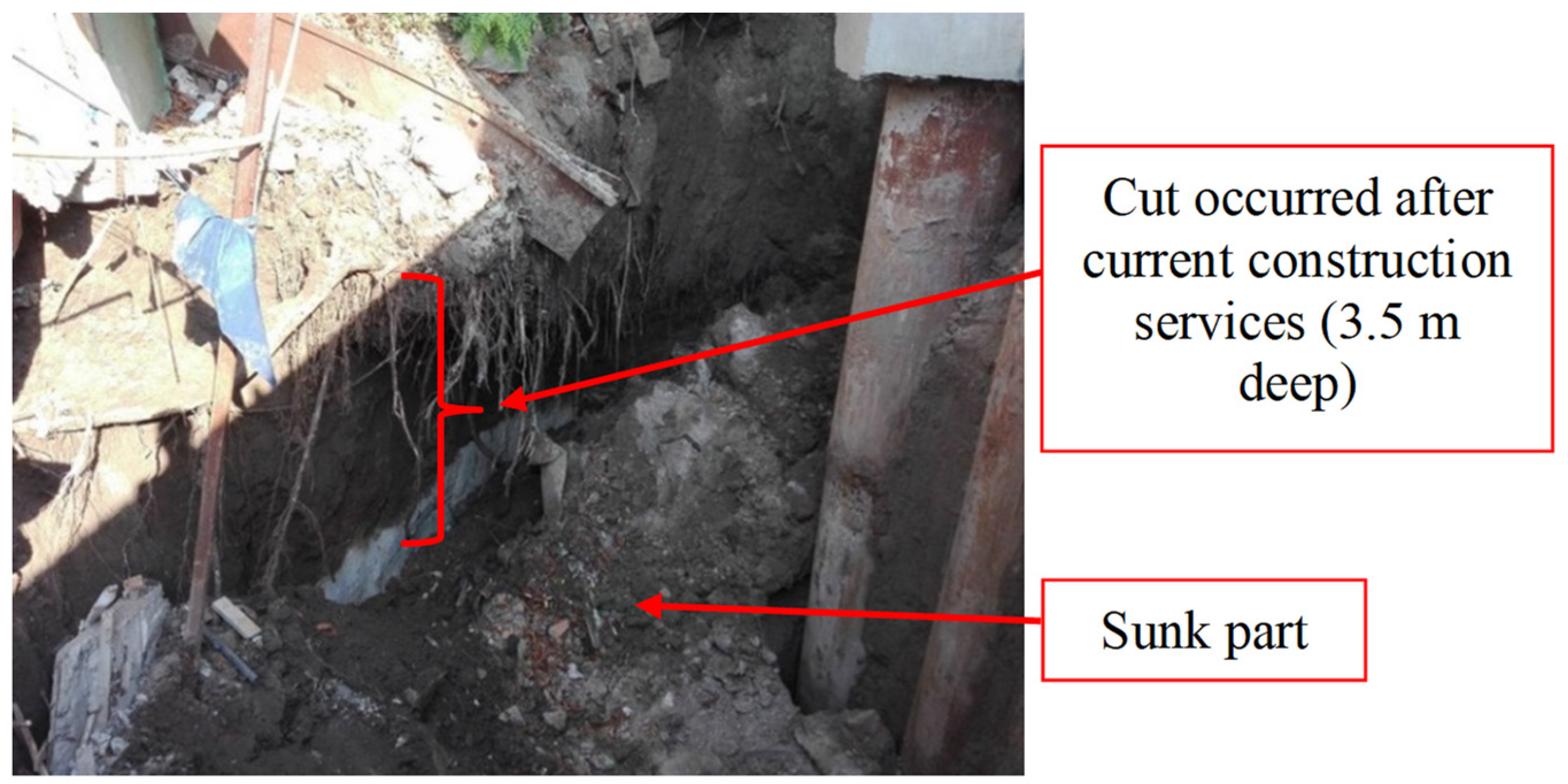
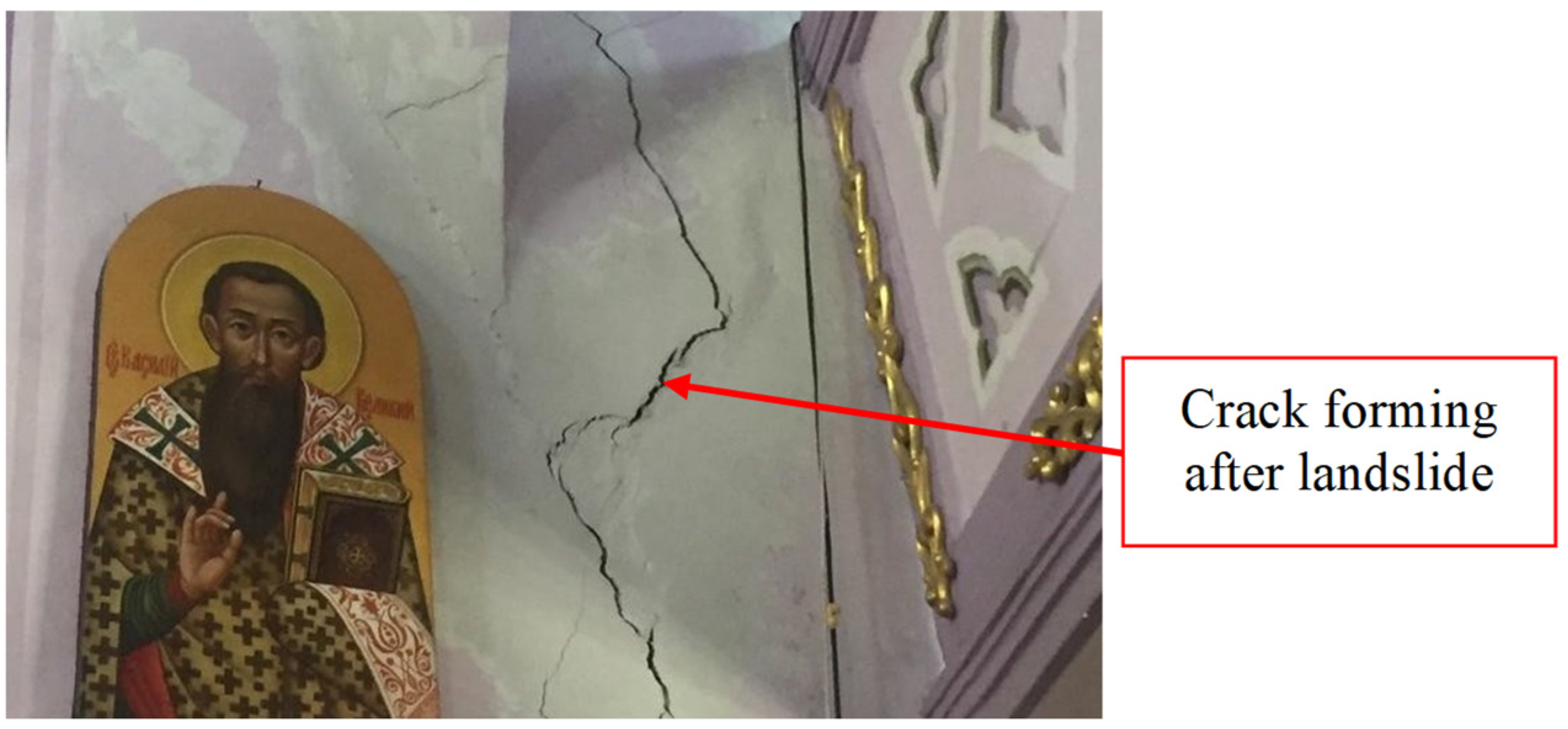
2.1. The Negative Impact on the State of Deformation of Landmarks

There are a number of processes that arise during the city’s functioning, which negatively affect the state of deformation of the territories on which it is built. These processes are often provoked by human engineering activities [29,30,31,32,33]. For example, the desire to wedge in a dense building is always associated with the impact on landmarks of a different value rank. The erection of new high-rise structures within the historic area of the city negatively affects the existing buildings [34,35].
Artificial processes of urbanization are also weighed down by natural influence—geological processes, such as soil degradation [36] and the changing properties of the base [37,38], are permanently acting. It should be noted that the constant straining of the daylight surface of the city is the process that should be characterized as having prime importance. This is not an exaggeration, since the controlled straining of slopes and soil foundations is a guarantee of the normal operation of all buildings, structures, and infrastructure.
The most important process that adversely affects the state of deformation in cities is the expansion of landslide hazard territories [39,40]. In this process, the topographic location of the city, its urban development, and natural landslide formation are connected. It is known that most modern metropolises, the existence of which goes back hundreds or thousands of years, were formed at altitudes (mountains, hills, slopes of beams or steep banks of rivers). This is due to the historical mentality since the location at height is strategic in the sense of the city’s defense. However, in our time, such a topographical position of cities complicates their functioning, since the load from buildings negatively affects the soil foundation.
The impact of temperature variables, weathering, soil suffusion, etc. lead to a gradual decrease in the stability of slopes, and thus engineering intervention is needed [41,42]. However, the expansion of landslide hazard territories is complicated by the presence of seismic processes: natural [43] and associated with engineering [44,45,46,47].
The impact of earthquakes (which are a widespread phenomenon) in many cases leads to the destruction of landslide hazard slopes and the landmarks built on them [48,49]. The emergence of such forceful actions, or their forecasting, requires early engineering alteration (strengthening bases and foundations, increasing the stability of slopes by building the retaining walls, or the use of pile structures, installation of seismically resistant belts, etc.). Even with a small probability of an earthquake, the complexity of seismic safety measures is a guarantee of the absence or minimization in the destruction of landmarks.
Equal impact occurs during the so-called industrial seismic activity. Pile driving, the work of equipment with periodic or pulse modes, transport, explosions during construction of underground structures, etc. should be evaluated on the basis of powerful computational complexes [50,51]. Neglect of such impacts may cause an emergency or even the destruction of landmarks, which requires monetary reconstruction in the future [52].
The presence of vibration actions also negatively affects buildings and structures, in particular those with historical significance [53]. In relation to the evaluation of the impact on rail transport, e.g., the metro, the action of construction equipment should be carried out using modern software [54,55]. In these studies, it is important to predict, in due time, the change in the state of deformation of bases and landslide hazard slopes when increasing the level of vibration [56] to that which the longstanding structures were not designed to withstand.
To illustrate the importance of the above-described multifaceted issue, examples are presented in the development of the state of deformation of landmarks of national significance in Ukraine. Importantly, in these examples, over the course of decades (even in the presence of severe deformations), the engineering protection was minimal. This characterizes negligent attitudes to landmarks and emphasizes the relatively low level of attention to the historical heritage.
On 29 June 2012, in Kyiv, there was a local landslide under the landmark of national significance “St. Andrew’s Church” (the security number is 26071-H). Because of the felling of trees, dynamic transport loads, vibrational impact of construction tools, and the active building of a slope (where the church is located), the subsoil has shifted by approximately 3–5 m3. The observation deck from the Dnieper’s side has lost support and hovered over the crest of the slope. In August 2017, there were local shears and subsidence of a daylight surface to a depth of up to 3.5 m, as a result of the intensification of construction works and cutting of a slope (Figure 1) [57].
On 13 December 2020, after eleven years of restoration works, the St. Andrew’s Church was open to visitors. However, landslide prevention works planned by the developers of Andrew’s Descent were not carried out. The monitoring of the state of deformation was not provided. This demonstrates the possibility of new soil landslides and subsidence of a daylight surface.
On 28 February 2018, in Lviv, the St. Illia Church (a landmark of national significance) received significant deformations (the security number is 130031-H). A landslide due to the technogenic groundwater rise was a cause. After that incident, it was decided to perform the landslide prevention works (Figure 2) [58].
As a third example, the St. Nicholas Gate of Kyiv Fortress is presented, which is also a landmark of national significance (the security number is 867/24). The St. Nicholas Gate is a unique fortified structure in Ukraine. On the edge of Nikolaivska Square (now Ivan Franko Square) in Kyiv, in 1846–1850, according to the architect P. Tamanskyi, a defensive barrack was erected for 500 people. It became a constituent part of the new Pechersk Fortress. In the center of the building, there is the St. Nicholas Gate, which represents two arched passages with columns previously decorated with column caps of Corinthian Order.
In 2017, the results of the building’s structural survey showed its unserviceability through the state of roofs, walls and cylindrical vaulted ceilings. This state was characterized by vertical and inclined cracks with an opening width of up to 20 mm, damage and destruction of brick masonry, etc. In accordance with the report on a preliminary evaluation of the construction impact on the hydrological regime and the slope stability, the local soil shear on the slope and the subsidence of the loessial soil under the foundations are the damage source.
The prediction of the situation suggested that, during soil moistening, there would be an activation of subsidence processes and a significant deterioration of straining soil properties. It was possible to activate the landslide process in the event of lengthy heavy rains or the melting of snow. It was decided that the problem of improving the state of deformation of this landmark of national significance would be solved immediately.

2.2. Ways to Solve the Problem

Improving the state of deformation should be based on innovative geotechnologies [59]. They minimally affect the functioning of the city and effectively reduce the impact of soil medium straining on architectural landmarks.
Geotechnology based on the use of geosynthetics is one of the most scientifically substantiated and approved techniques [60,61]. This geotechnology has been applied for a long time using natural materials. It saw a significant increase in development after the invention of plastics. The immersion of various kinds of canvases, meshes, membranes and antivibration mats into the soil foundation significantly reduces its straining. However, the complexity in the application of this geotechnology when strengthening already existing buildings is the practical impossibility of introducing a geosynthetic element. This geotechnology was most common not during the reconstruction of the old but in the construction of new buildings and structures.
The same complexity indicates the creation of low-stress-related layers in a weak soil foundation [62,63,64], that is, earth-rammer or setting in broken stone [65]. This geotechnology is effective when reducing deformations of buildings and structures. However, its implementation is most appropriate at construction, rather than during the measures to improve the state of deformation [66].
The original geotechnology is the application of special piles [67], screwed into a soil foundation. This technology is expedient to use both during construction and the reconstruction of the structure. However, the European standards have not yet been developed for this type of piles and their significant cost restrains the extensive application of such geotechnology.
From the viewpoint of reducing the state of deformation of soil foundations and landslide hazard slopes, boring, mixing technology and jet-grouting are the most effective ones [68,69,70]. The conceptual scientific idea of these technologies is strengthening weak soil by changing its bond and deformation characteristics. The essence of both of these geotechnologies is the destruction of the soil structure and mixing or partial substitution of it by cementing substance in “mix-in-place” mode [71,72]. Destruction occurs due to a liquid jet, and the liquid itself performs the function of binding the soil particles [73]. The difference in these closest (in the conceptual sense) geotechnologies is the pressure value. When applying boring and mixing technology, the pressure of a cutting jet does not even reach ten atmospheres, whereas in case of jet-grouting it reaches hundreds of atmospheres.
Jet-grouting technology appeared as an alternative one to chemical injection, which is not only an expensive but also a toxic method. This technology has been widely used and distributed since the early 1980s for a wide range of engineering–geological conditions and physical and mechanical properties of soils. They are, in fact, the principal factors affecting the geometric size of elements and hardness of a geomaterial–soil–cement [74]. The elements of reducing the deformation state of soil foundations and landslide hazard slopes columns are formed from it (Figure 3).
Jet-grouting technology allows it to be used when improving the state of deformation for the landslide hazard slopes and soil foundations. Depending on the number of fluid flows involved in the process of forming soil–cement elements, the technology is divided into one-component (one flow), two-component (two flow) and three-component (three flow) varieties.
When improving the state of deformation of the landmark highlighted in the article, a one flow variety of jet-grouting was used [75]. Its essence is the fact that both destruction and cementation of soil occur with the help of cement slurry. It is supplied under high pressure (several hundred atmospheres) through the pump to the jet-blowing monitor. At the exit of the monitor, the velocity of the fluid jet is very quickly reduced. The destructive efficiency of one flow (simple) jet in the direction from the well axis is limited. The working radius of the jet of cement slurry in the soil is equal to several tens of centimeters. As a result of soil treatment with one flow jet, a column is formed from 0.4 to 1.4 m in diameter.
Over the past twenty years, jet-grouting has obtained new solutions that affect the load-carrying capacity of strengthening elements. The main solution is the reinforcement of the soil–cement pile immediately after its creation. The reinforcement by steel frames is currently widespread, but the technology of reinforcing by fiber is the more progressive [76].
Thus, from the above methods to reduce the state of deformation of soil foundations and landslide hazard slopes, jet-grouting is the most rational one, one which minimally affects the ancient building and allows us to increase the strength of the soil.

3. Materials and Methods

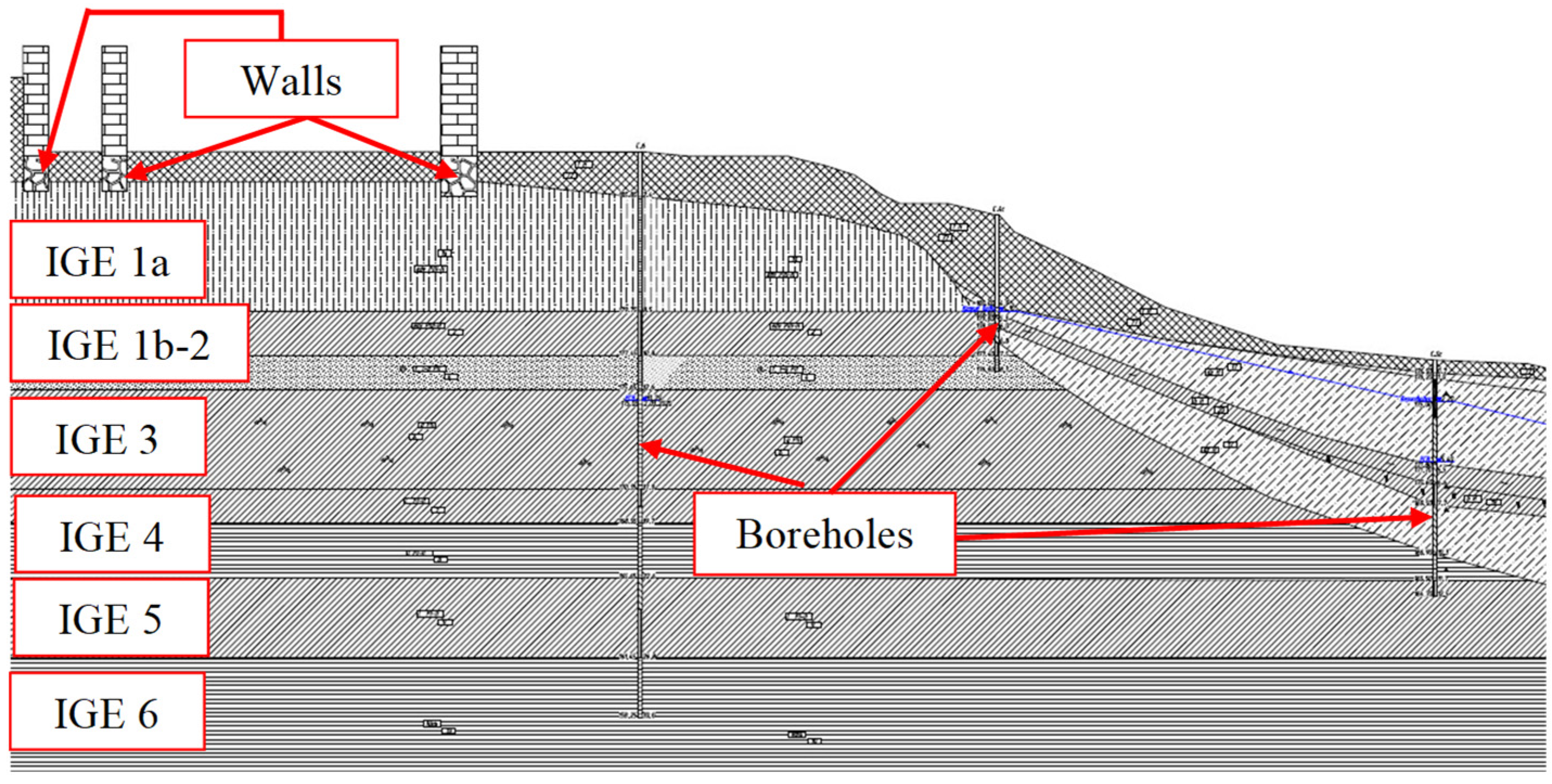
3.1. Analysis of States

Before implementation of actions to improve the state of deformation for the St. Nicholas gate, engineering and geological research, technical evaluation and operational suitability of the building were performed.
In the physical and geographical relation, the investigated area is located at the intersection of the zones of Mixed forests and the Forest-steppe zone of the Pridneprovska headland region. In geomorphological relation, the section of surveys is located in the selvedge of the Kyiv loessial plateau and the crest of the slope to the Dnipro valley. In the northeastern part, the section borders with a steep slope to the Dnipro River.
The evaluation of the state of landslide hazard slopes at the current scientific level is impossible without studying the properties of rocks (components of the slopes) and it is stipulated by a very large number of various factors. Only a detailed recognition of the morphology, steepness, and height of the slopes, the engineering and geological structure and properties of the rocks, as well as a complex set of external impacts, make it possible to resolve the issue of evaluating the stability of landslide hazard slopes. It is also important that the carrying out of such studies allows predicting the behavior both in the course of natural behavior and during the construction activities within slopes.
In accordance with the results of engineering and geological research of this object, the levels of groundwater in the wells were set at depths of 7.7–14.5 m. The site of the project-oriented building is relating to the flooded territories. The structure of the Earth’s upper crust is double-level. The lower structural level is an Archaean–Proterozoic crystalline basement, the upper-Meso-Cenozoic sedimentary apron, which occurs at the denuded surface of the ground, and it has a common flat slope in the northeast direction. Thus, the slope (on which the St. Nicholas gate was erected) has a complex engineering and geological structure of a landslide hazard slope (Figure 4).
The engineering–geological structure of the landslide hazard slope consists of the following engineering–geological elements (IGE):
  • IGE 1a—sandy loam silt, yellow-gray, pale-yellow, stiff, loess-like, subsidental;
  • IGE 1b—sandy loam silt, yellow-gray, loessial, plastic;
  • IGE 2—clay loam light and heavy silty, brownish-yellow, and low-plastic;
  • IGE 3—clay loam light arenaceous and silty, brownish-, yellow-grey, soft-plastic to low-plastic, with rare inclusions of carbonate bundles;
  • IGE 4—sand silt, yellow-grey, dense, from a small degree of water saturation to saturated with water;
  • IGE 5—sandy loam, brownish-grey, brown, plastic to solid, with sand lenses 10%, inclusions of crushed aggregates and grit of crystalline rocks 5%, with carbonate bundles 2.0–12.0 mm 10%;
  • IGE 6—clay loam heavy and light arenaceous, brown, brownish-gray, semi-solid, dense, inclusions of crushed aggregates and grit of crystalline rocks 5%, with carbonate bundles 2.0–12.0 mm 10%.
In the engineering–geological structure, there are technogenic sources of water saturation of the soil, which determines the differentiated moisture of the slope soils and various activity of sheet and linear erosion. The negative features of the engineering–geological conditions of this site include: the presence of weak plastic soils (IGE 3, IGE 6) in the section, expansion of subsidental loess-like soils in the upper part of the site, the presence of a disordered landslide slope and technogenic topwaters within the slope and proximity of neighboring buildings. Loess-like sandy loams present in a section (IGE 1a) have subsidental properties. At a pressure of 0.1 MPa, the value of the relative deformation of the subsidence is 0.012. The initial pressure of the subsidence is 78 kPa on average.

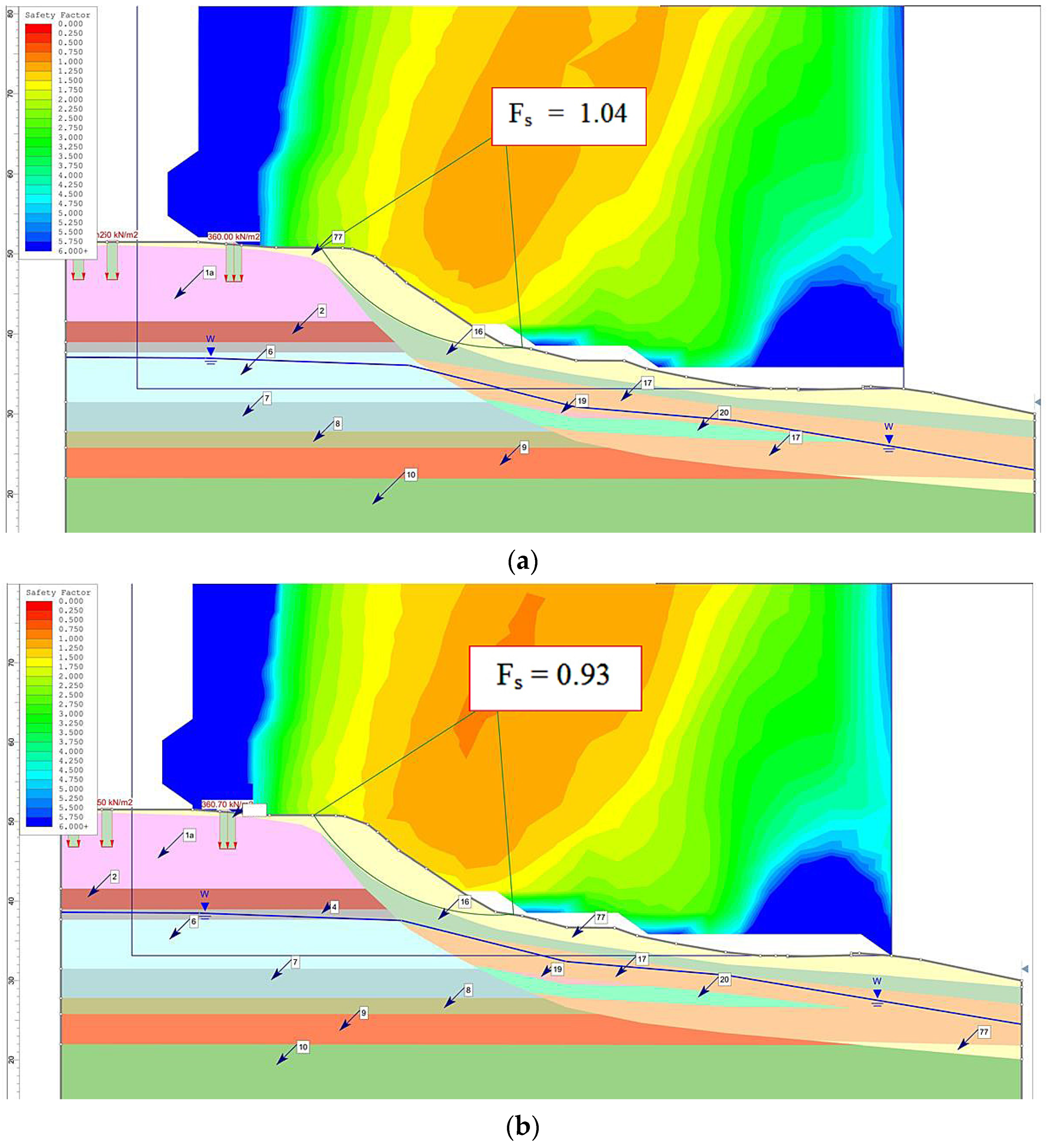
3.2. Analytical Evaluation of the Landslide Hazard Slope Stability

In order to evaluate the state of the landslide hazard slope on which the landmark is built, stability in the natural and predictive states was calculated using the computational complex RocScience Slide. The complex analyzes the stability of the sliding surfaces (using methods of limit equilibrium of vertical modules) and allows you to determine the critical sliding surface for this slope. These methods come from the given below preconditions:
  • The stability loss mechanism is taken as a process of sliding a massif relative to the fixed part of the slope. The dividing line is called a sliding surface;
  • The shearing resistance over the sliding surface is calculated for static conditions. Along the entire surface, it must be upheld the criterion of soil destruction, which is taken in the form of the Coulomb’s law;
  • The true stress of the displacement obtained on the basis of calculation is compared with the limit shearing resistance. The result of this comparison is expressed as the stability safety factor Fs. For the selected sliding surface, the stability safety factor Fs is this indicator when the strength characteristics (an angle of internal friction and the specific cohesion) along the entire surface are reduced by Fs times. The separated massif as a whole will be in a state of limit equilibrium. The stability margin factor of the slope (escarp) Fs is the minimum one among the stability margin factors in all possible sliding surfaces that satisfy the specified limits.
In the computational complex RocScience Slide, several classical methods for the analysis of slopes stability are implemented as follows: Bishop; Spencer; Corps of Engineers No.1; Lowe and Karafiath; Janbu. The differences in the given methods are in static equilibrium conditions (Table 1).
The model of the object under consideration, used to define the slope stability in the computational complex RocScience Slide is shown in Figure 5.
The model of the computational complex RocScience Slide shows all the geometric dimensions of the landslide hazard slope under study as well as the engineering–geological structure of the landslide hazard slope (see Figure 4) and soil properties. As a method for calculating slope stability, the Janbu method is adopted. It gives the realistic value of the stability safety factor Fs, but with some of these values are underestimated. This is further taken into account in the safety margin of construction using jet-grouting technology.

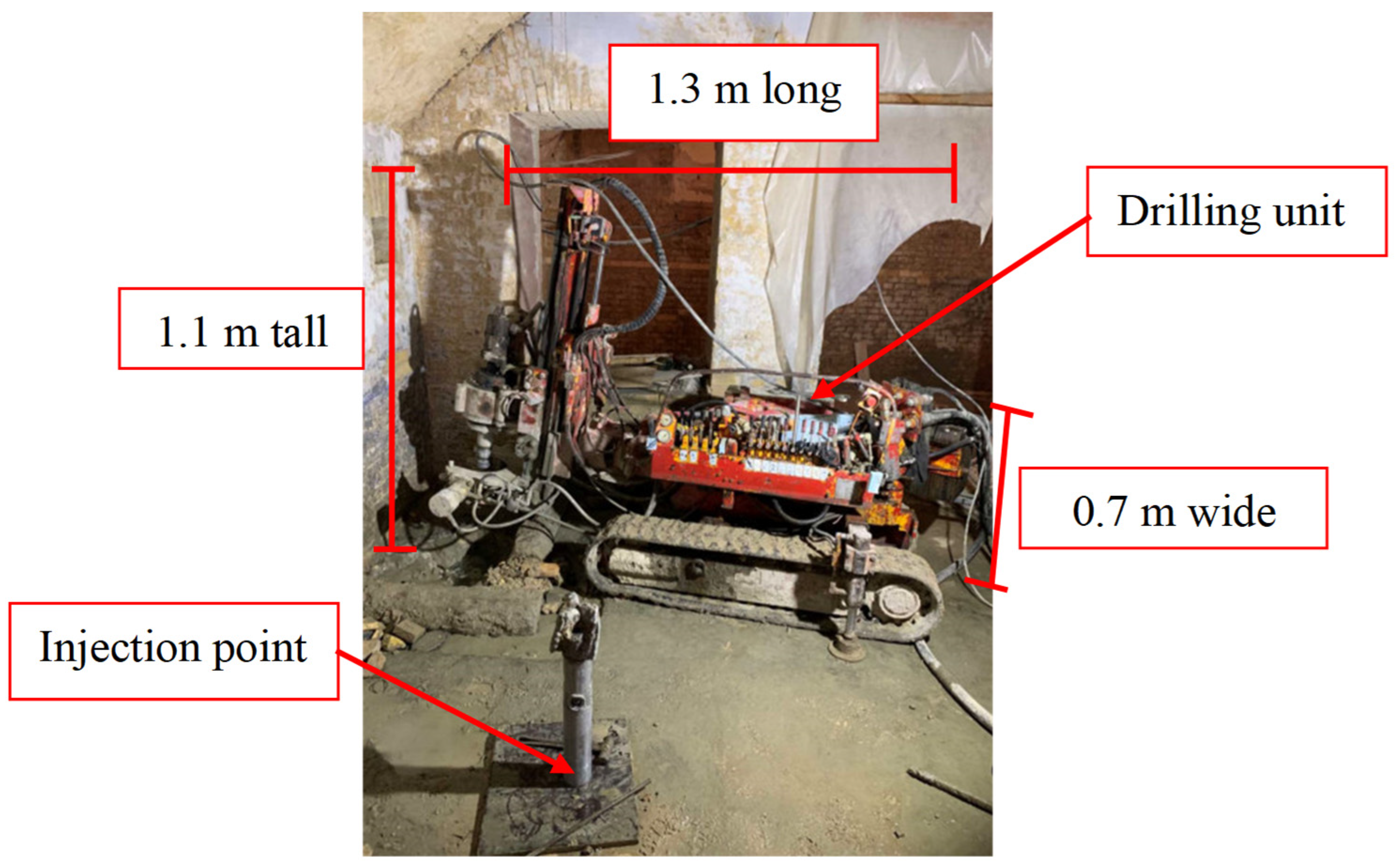
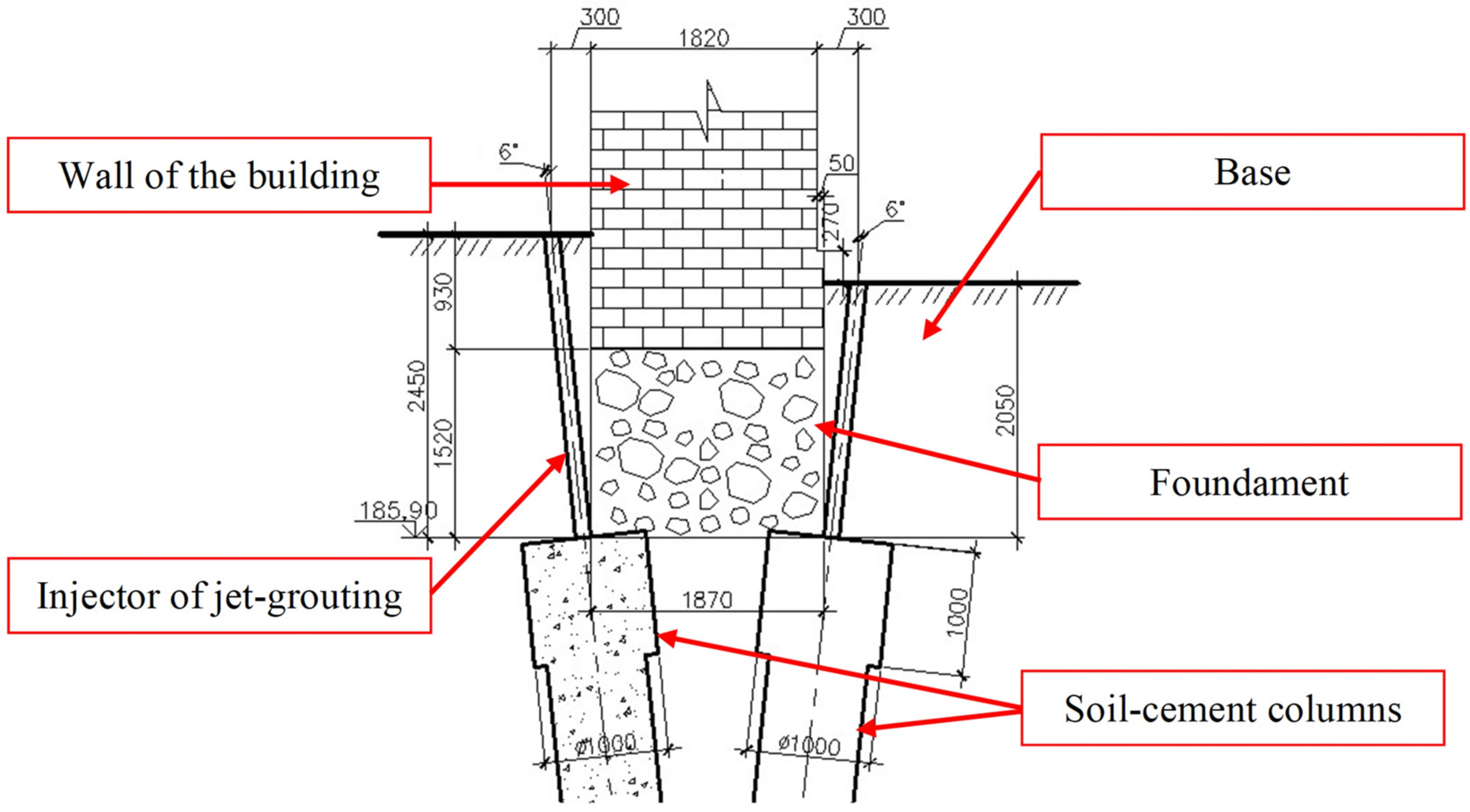
3.3. Jet-Grouting Technology

The problem of improving the state of deformation for the St. Nicholas Gate is urgent and received a decision based on the use of jet-grouting technology.
The structure of jet-grouting technological operations is the following: (1) preliminary drilling of a borehole (∅125–135 mm) with simultaneous lowering of the hydromonitor to the project mark of the bottom of the future element; (2) connecting the hydromonitor to a high pressure pump; (3) supplying the mortar in a flexible sleeve to the monitor’s nozzles under high pressure (∅1.6–2.2 mm); (4) step-by-step raising of a hydromonitor with rotation; (5) eroding the soil with a jet of the mortar and the formation of an element filled with a soil–cement mixture; (6) lifting a part of the eroded soil with the spent mortar toward the surface in the form of pulp on the gap between the borehole and tools.
The main working parameters of the technology of jet cementation are: the rate of raising the hydromonitor and the velocity of its rotation, the pressure of the mortar and its density, mortar rate, diameter and number of nozzles. All these parameters in a varying degree affect the strength, diameter and sizes of soil–cement columns.
For the jet-grouting application, a set of technological equipment is used that ensures all operations. When choosing a drilling unit, the conditions of jet-grouting play an important role. In the open areas, both small-sized and large-sized drilling machines are possible. In a limited space (inside the building, in the basement parts, in door openings) one can use small drilling units (Figure 6).
An important feature of the technology application is strengthening the soil base of the foundations of existing buildings, due to the absence of shock and vibration loads. These advantages of jet-grouting make it maximally efficient to perform the strengthening of the foundations of historic buildings and landmarks, where building machinery can cause irreparable harm.

4. Discussion

4.1. Results of Evaluating the Landslide Hazard Slope Stability

In the model of the RocScience Slide computational complex, several scenarios have been simulated to evaluate the impact of the jet-grouting technology application on the landslide hazard slope stability. The “zero” scenario is the behavior of the slope, where the St. Nicholas Gate was built in natural state. The normative stability safety factor Fs under these conditions is 1.25.
One predicted state (“pessimistic” scenario) was simulated, taking into account the possible raising of groundwater levels by 1.5 m and moisturizing the upper layers of the soil as a result of atmospheric precipitation. In accordance with the obtained results, the slope within the construction site has a risk of landslide (Fs = 1.04–1.41) (Figure 7a), and its separate part is landslide (Fs = 0.92–0.93) (Figure 7b).
Calculations of the slope stability directly adjacent to a part of the building indicate the need for landslide prevention works to improve the state of deformation. The second predicted state (“optimistic” scenario) reflects the situation after landslide prevention works (Figure 7c). The stability margin factor for the “optimistic” scenario (Fs = 1.266), unlike the “zero” and “pessimistic” increases by 1.21–1.37, the depth of passing the minimum calculated sliding curve on the track of the retaining wall is 18–21 m from the Earth’s surface. This indicates the slope stability, and the effectiveness of landslide prevention works to improve the state of deformation for this landmark.
According to the results of the calculations, landslide prevention works were designed to improve the state of deformation of the landslide hazard slope. The design of the landslide protection retaining wall is made of 35 drowning piles, each with a length of 22.0 m, a diameter of 1020 mm and a step of 1.5 m. The total length of a landslide protection wall was 51.0 m. The binder grating is installed on the heads of piles, which provides compatibility of piles work.

4.2. The Practical Solution to the Problem of Improving the State of Deformation

After performing work to improve the state of deformation for the slope adjacent to the building, the strengthening of its soil foundation was conducted (Figure 8).
The strengthening was in the creation of soil–cement columns performed by the jet injection technology. Soil–cement columns had a length of 12 m and a diameter of 0.8 m, with the expansion of 1.0 m in the upper part. The total number of columns amounted to 478 pcs. For the construction of columns, an artificial cement of grade 400 was used. The erection of columns on both sides of the foundations allowed for the uniform distribution of the load from the historical building and reduced the straining of the soil foundation. A small-size drilling unit allowed to perform soil–cement elements inside the building in a limited space.

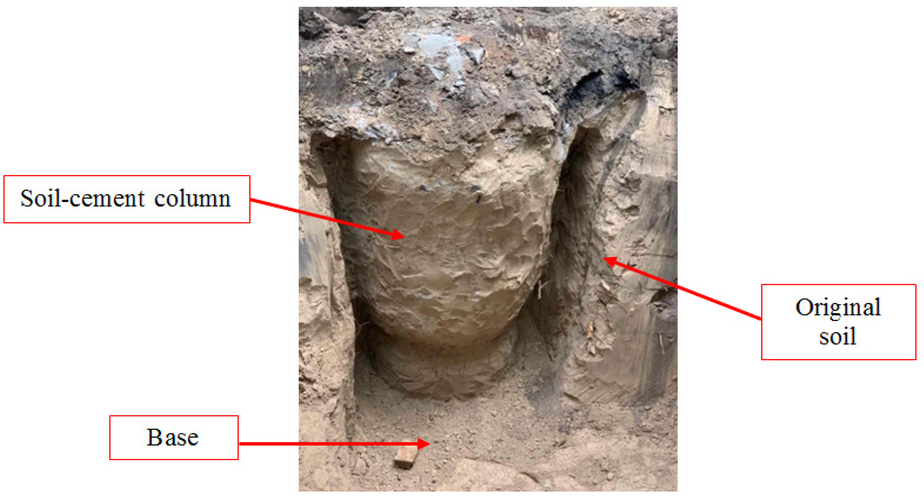
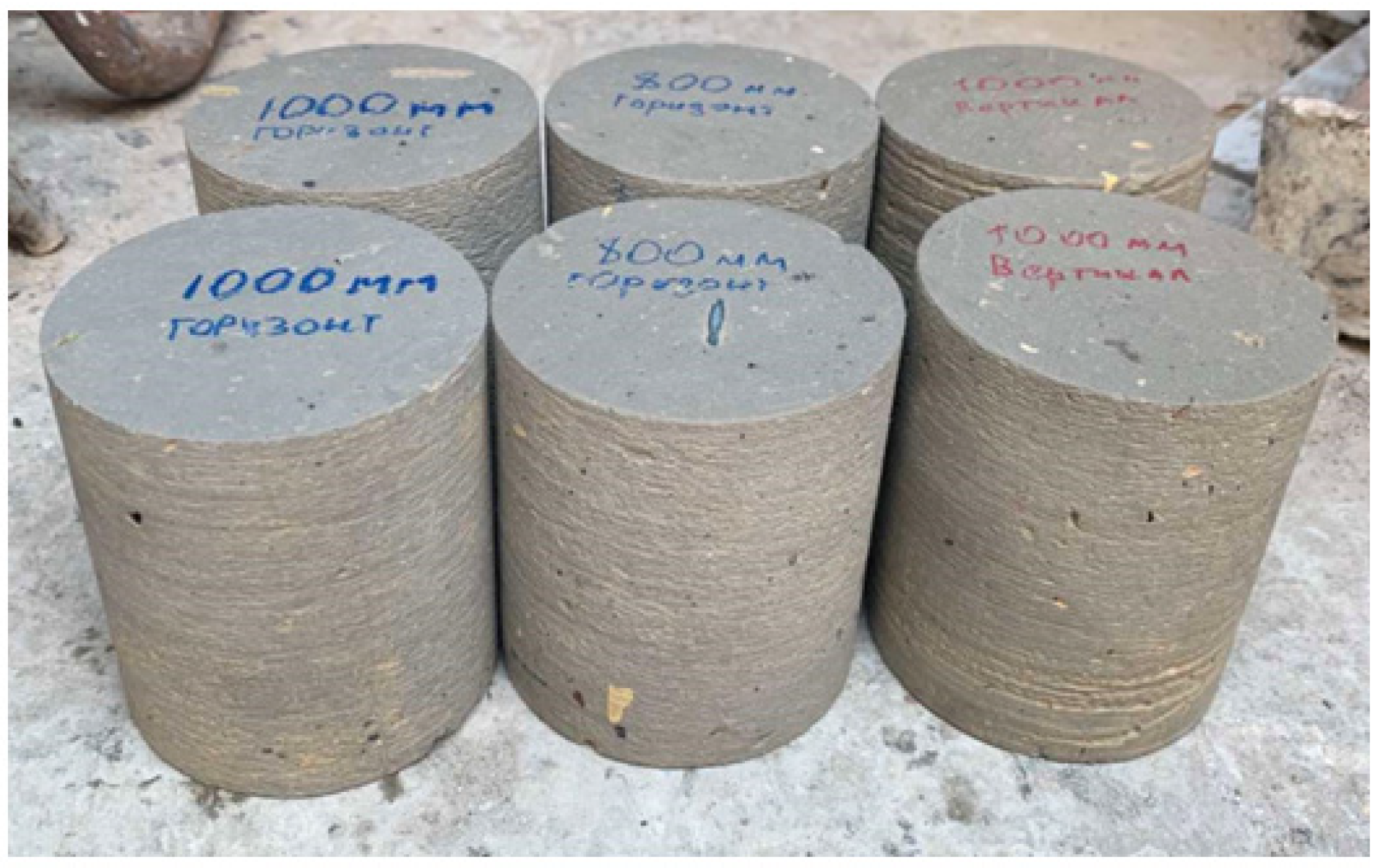
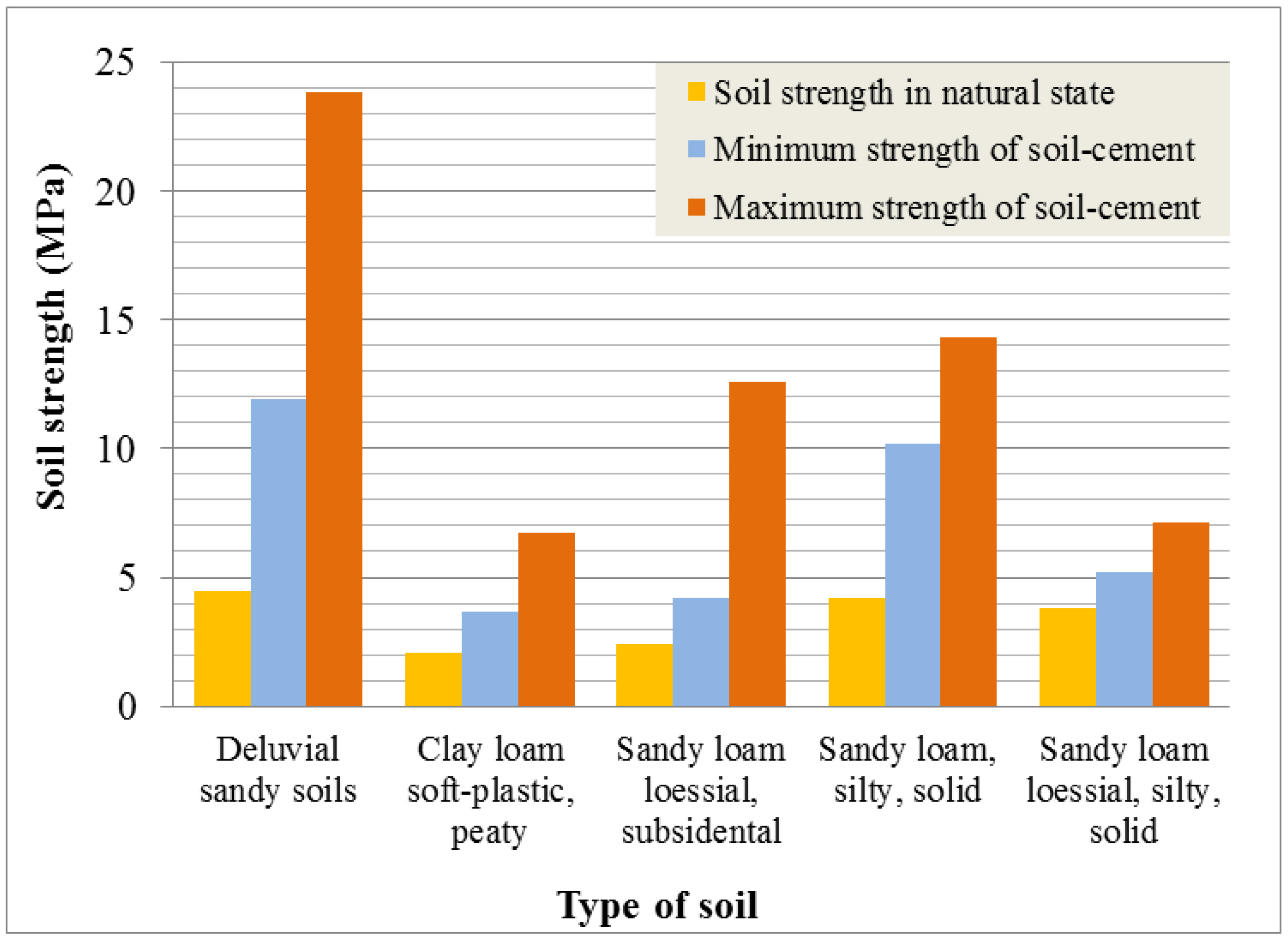
4.3. Patterns of Deformation and Strength Indicators of Soil–Cement

After finishing the complex works, shaft excavation with diameter measurements of the soil–cement column was performed; this is made to study the material of the soil–cement column and confirm the diameters. The samples of soil–cement (cores) were selected from the column that was executed in the soil layer IGE-1-a (sandy-loam loess-like, subsidental) (Figure 9).
The soil layer IGE-1-a (sandy-loam loessial, subsidental) has the following characteristics: in natural state γ = 1.66 ton/m3, c = 24 kPa, φ = 24°, E = 13 MPa; in water saturated state γ = 1.83 ton/m3, c = 9 kPa, φ = 18°, E = 6 MPa. Deformation indicators of soils are obtained in odometers, which exclude the possibility of lateral expansion of the soil sample at its load with vertical pressure up to 0.3–0.6 MPa. Indicators of soil strength are obtained during tests made in the devices of single-plane cut with loads of 0.1–0.15–0.2; 0.1–0.2–0.3; 0.2–0.3–0.4 MPa according to the test schemes of a consolidated-drained and unconsolidated-undrained cut. Tests were carried out on samples of natural moisture and saturated with water.
According to the results of the soil–cement, the lowest compression strength rate was 5.2 MPa, while the highest was 7.1 MPa. The strength on the compression of soil–cement material in the loess-like sandy-loams varied from 3.0 to 12.0 MPa. Based on experimental data (obtained in the creation of soil–cement elements in various engineering–geological conditions in Ukraine), we present the results in Table 2 and in Figure 10.
The comparison of ranges of obtained strength parameters for the soil–cement was performed (which was selected from columns in the strengthening of the St. Nicholas Gate) with previously obtained values in similar ground conditions. Analyzing the strength diagram of soils and soil–cement (Figure 10), we can say about increasing the strength of columns on average 1.6–4.0 times. This indicates the effectiveness of the jet-grouting application, especially in deluvial sandy soils and sandy loams.

5. Conclusions

  • As an example of the effective application of jet-grouting, the St. Nicholas Gate of Kyiv Fortress is given, which is landmarks of national significance (the security number is 867/24). To improve its state of deformation, engineering–geological surveys are performed, evaluating the technical state and operational suitability of the building.
  • An analytical evaluation of the landslide hazard slope stability in the computational complex RocScience Slide is carried out, which shows that in the presence of landslide prevention works, the stability margin factor is increased by 1.21–1.37.
  • The algorithm of the main stages in performing the landslide prevention works to stabilize the adjacent slope, where the St. Nicholas Gate is built, was described. The technological parameters of soil strengthening in the base of a building with the jet-grouting application are presented. The conducted measurements of the performed elements of strengthening prove the correctness in selecting technological parameters of drilling equipment, the correspondence of actual diameters to the projected and expected values of the strength of soil–cement material on compression.
  • The strength parameters of the soil–cement obtained during the jet-grouting application indicate an increase in the strength of columns on average by 1.6–4.0 times. This proves the effective jet-grouting application to improve the state of deformation of the landmarks of national significance. Works upon the realization of this geotechnology, executed on the example of the St. Nicholas Gate, can be recommended for application in such cases in other cities of the world.

Author Contributions

Conceptualization, A.S., A.d.M.W., O.T., V.G. and L.N.; methodology, A.S., A.d.M.W., O.T., V.G. and L.N.; software, A.S., A.d.M.W., O.T., V.G. and L.N.; validation, A.S., A.d.M.W., O.T., V.G. and L.N.; investigation, A.S., A.d.M.W., O.T., V.G. and L.N.; resources, A.S., A.d.M.W., O.T., V.G. and L.N.; writing—original draft preparation, A.S., A.d.M.W., O.T., V.G. and L.N.; writing—review and editing, A.S., A.d.M.W., O.T., V.G. and L.N.; visualization, A.S., A.d.M.W., O.T., V.G. and L.N.; supervision, A.S., A.d.M.W., O.T., V.G. and L.N. All authors have read and agreed to the published version of the manuscript.

Funding

This research received no external funding.

Institutional Review Board Statement

Not applicable.

Informed Consent Statement

Not applicable.

Data Availability Statement

Not applicable.

Conflicts of Interest

The authors declare no conflict of interest.

References

  1. International Council on Monuments and Sites (ICOMOS). The Athens Charter for the Restoration of Historic Monuments. In Proceedings of the First International Congress of Architects and Technicians of Historic Monuments, Athens, Greece, 21–30 October 1931. [Google Scholar]
  2. International Council on Monuments and Sites (ICOMOS). The Venice Charter: International charter for the conservation and restoration of monuments and sites. In Proceedings of the IInd International Congress of Architects and Technicians of Historic Monuments, Venice, Italy, 25–31 May 1964. [Google Scholar]
  3. Chapapría, J.E. Estudios previos a la restauración de monumentos. In Restauración Arquitectónica; Bermejo, I.R., Ed.; University of Valladolid, Secretariat for Publications and Scientific Exchange: Valladolid, Spain, 1998; Volume 1, pp. 159–176. [Google Scholar]
  4. Taraszkiewicz, A. Revitalization of Residential Buildings Dating Back to the Late 19th and Early 20th Century on the Example of “Willa Halina” in Sopot (Poland). Buildings 2021, 11, 279. [Google Scholar] [CrossRef]
  5. Li, Y.; Li, X.; Jiang, Q.; Zhou, Q. Historical Study and Conservation Strategies of “Tianzihao” Colony (Nanjing, China)—Architectural Heritage of the French Catholic Missions in the Late 19th Century. Buildings 2021, 11, 176. [Google Scholar] [CrossRef]
  6. Vitali, F.; Caldi, C.; Benucci, M.; Marzaioli, F.; Moioli, P.; Seccaroni, C.; De Ruggieri, B.; Romagnoli, M. The vernacular sculpture of Saint Anthony the Abbot of Museo Colle del Duomo in Viterbo (Italy). Diagnostic and Wood dating. J. Cult. Herit. 2021, 48, 299–304. [Google Scholar] [CrossRef]
  7. Zysk, E.; Źróbek-Sokolnik, A.; Dynowski, P.; Źróbek-Różańska, A. Sustainable residential development in rural areas in relation to nature conservation. Environmental Engineering. In Proceedings of the 10th International Conference on Environmental Engineering, ICEE, Vilnius, Lithuania, 27–28 April 2017. [Google Scholar] [CrossRef]
  8. Ćwirko, M.; Jastrzębska, M.; Kwiecień, S. The analysis of the usefulness of welded meshes to embankment reinforcement. Studia Geotech. Et Mech. 2017, 39, 3–9. [Google Scholar] [CrossRef] [Green Version]
  9. Lemes, Í.J.M.; Dias, L.E.S.; Silveira, R.A.M.; Silva, A.R.; Carvalho, T.A. Numerical analysis of steel–concrete composite beams with partial interaction: A plastic-hinge approach. Eng. Struct. 2021, 248, 113256. [Google Scholar] [CrossRef]
  10. Mičian, M.; Winczek, J.; Gucwa, M.; Koňár, R.; Málek, M.; Postawa, P. Investigation of welds and heat affected zones in weld surfacing steel plates taking into account the bead sequence. Materials 2020, 13, 5666. [Google Scholar] [CrossRef] [PubMed]
  11. Moropoulou, A.; Labropoulos, K.; Delegou, E.T.; Karoglou, M.; Bakolas, A. Non-destructive techniques as a tool for the protection of built cultural heritage. Constr. Build. Mater. 2013, 48, 1222–1239. [Google Scholar] [CrossRef]
  12. Owen, T.E. Special issue on ground penetrating radar. J. Appl. Geophys. 1995, 33, 1–255. [Google Scholar]
  13. Leucci, G. Ground-penetrating radar survey to map the location of buried structures under two churches. Archaeol. Prospect. 2002, 9, 217–228. [Google Scholar] [CrossRef]
  14. Christaras, B.; Auger, F.; Mosse, E. Determination of the moduli of elasticity of rocks. Comparison of the ultrasonic velocity and mechanical resonance frequency methods with direct static methods. Mater. Struct. 1994, 27, 222–228. [Google Scholar] [CrossRef]
  15. Azimi, M.; Eslamlou, A.D.; Pekcan, G. Data-Driven Structural Health Monitoring and Damage Detection through Deep Learning: State-of-the-Art Review. Sensors 2020, 20, 2778. [Google Scholar] [CrossRef]
  16. Ramiaczek, P.; Chomicz-Kowalska, A.; Stepien, J.; Iwanski, M.M.; Maciejewski, K. Preliminary assessment of the secondary setting of Portland cement in recycled crushed concrete incorporated in cold recycled road base mixes with foamed bitumen. IOP Conf. Ser. Mater. Sci. Eng. 2019, 603, 042076. [Google Scholar] [CrossRef]
  17. Mabkhot, M.M.; Ferreira, P.; Maffei, A.; Podržaj, P.; Mądziel, M.; Antonelli, D.; Lanzetta, M.; Barata, J.; Boffa, E.; Finžgar, M.; et al. Industry 4.0 Enabling Technologies into United Nations Sustainability Development Goals. Sustainability 2021, 13, 2560. [Google Scholar] [CrossRef]
  18. Egidi, G.; Salvati, L.; Cudlin, P.; Salvia, R.; Romagnoli, M. A New ‘Lexicon’ of Land Degradation: Toward a Holistic Thinking for Complex Socioeconomic Issues. Sustainability 2020, 12, 4285. [Google Scholar] [CrossRef]
  19. Pietrzak, K.; Pietrzak, O.; Montwiłł, A. Light Freight Railway (LFR) as an innovative solution for Sustainable Urban Freight Transport. Sustain. Cities Soc. 2021, 66, 102663. [Google Scholar] [CrossRef]
  20. Sekulic, D.; Vdovin, A.; Jacobson, B.; Sebben, S.; MoeJohannesen, S. Effects of wind loads and floating bridge motion on intercity bus lateral stability. J. Wind. Eng. Ind. Aerodyn. 2021, 212, 104589. [Google Scholar] [CrossRef]
  21. Okraszewska, R.; Romanowska, A.; Wołek, M.; Oskarbski, J.; Birr, K.; Jamroz, K. Integration of a multilevel transport system model into sustainable Urban mobility planning. Sustainability 2018, 10, 479. [Google Scholar] [CrossRef] [Green Version]
  22. Sambito, M.; Severino, A.; Freni, G.; Neduzha, L. A Systematic Review of the Hydrological, Environmental and Durability Performance of Permeable Pavement Systems. Sustainability 2021, 13, 4509. [Google Scholar] [CrossRef]
  23. Strelko, O.; Kyrychenko, H.; Berdnychenko, Y.; Petrykovets, O.; Soloviova, L. Enhancement of the technology for the distribution of gondola railcars for loading in a competitive environment. In Proceedings of the 24th International Scientific Conference on Transport Means, Part I, Kaunas, Lithuania, 30 September–2 October 2020; pp. 182–186. [Google Scholar]
  24. Oliskevych, M.; Pelo, R.; Prokudina, I.; Silenko, V.; Sorokivskyi, O.; Zaiats, O. Optimization of vehicle speed forecasting horizont on the intercity highway. East. Eur. J. Enterp. Technol. 2020, 3, 57–68. [Google Scholar] [CrossRef]
  25. Severino, A.; Martseniuk, L.; Curto, S.; Neduzha, L. Routes Planning Models for Railway Transport Systems in Relation to Passengers’ Demand. Sustainability 2021, 13, 8686. [Google Scholar] [CrossRef]
  26. Binda, L.; Saisi, A.; Tiraboschi, C. Investigation procedures for the diagnosis of historic masonries. Constr. Build. Mater. 2000, 14, 199–233. [Google Scholar] [CrossRef]
  27. Kujawa, M.; Lubowiecka, I.; Szymczak, C. Finite element modelling of a historic church structure in the context of a masonry damage analysis. Eng. Fail. Anal. 2020, 107, 104233. [Google Scholar] [CrossRef]
  28. Grilland, N.; Chiozzi, A.; Bondi, F.; Tralli, A.; Manconi, F.; Stochino, F.; Cazzani, A. Numerical insights on the structural assessment of historical masonry stellar vaults: The case of Santa Maria del Monte in Cagliari. Contin. Mech. Thermodyn. 2021, 33, 1–24. [Google Scholar] [CrossRef]
  29. Gallo, M.; Botte, M.; Ruggiero, A.; D’Acierno, L. A Simulation Approach for Optimising Energy-Efficient Driving Speed Profiles in Metro Lines. Energies 2020, 13, 6038. [Google Scholar] [CrossRef]
  30. Goolak, S.; Liubarskyi, B.; Sapronova, S.; Tkachenko, V.; Riabov, I.; Glebova, M. Improving a model of the induction traction motor operation involving non-symmetric stator windings. East. -Eur. J. Enterp. Technol. 2021, 4, 45–58. [Google Scholar] [CrossRef]
  31. Shavolkin, O.; Shvedchykova, I.; Kravchenko, O. Three-phase Grid Inverter for Combined Electric Power System with a Photovoltaic Solar Battery. In Proceedings of the International Conference on Modern Electrical and Energy Systems, MEES 2019, Kremenchuk, Ukraine, 23–25 September 2019; pp. 318–321. [Google Scholar] [CrossRef]
  32. Ticali, D.; Denaro, M.; Barracco, A.; GuHrrieri, M. Piezoelectric Energy Harvesting from Raised Crosswalk Devices. In Proceedings of the International Conference on Numerical Analysis and Applied Mathematics 2014 (ICNAAM-2014), Rhodes, Greece, 22–28 September 2014; Volume 1648, pp. 780006-1–780006-4. [Google Scholar] [CrossRef]
  33. Barberi, S.; Sambito, M.; Neduzha, L.; Severino, A. Pollutant Emissions in Ports: A Comprehensive Review. Infrastructures 2021, 6, 114. [Google Scholar] [CrossRef]
  34. Ayensa, A.; Beltrán, B.; Ibarz, E.; Gracia, L. Application of a new methodology based on eurocodes and finite element simulation to the assessment of a romanesque church. Constr. Build. Mater. 2015, 101, 287–297. [Google Scholar] [CrossRef] [Green Version]
  35. Penelis, G.; Penelis, G. Restoration of the Margirgis Church and Roman Tower in Cairo. Struct. Eng. Int. 2020, 30, 64–73. [Google Scholar] [CrossRef]
  36. Salvati, L.; Gemmiti, R.; Perini, L. Land degradation in Mediterranean urban areas: An unexplored link with planning? Area 2012, 44, 317–325. [Google Scholar] [CrossRef]
  37. Błazik-Borowa, E.; Jami’nska-Gadomska, P.; Pie´nko, M. Influence of Foundation Quality on the Stress in the Elements of Steel Façade Scaffolding. Buildings 2020, 10, 130. [Google Scholar] [CrossRef]
  38. Lepirica, A. Genesis of inner gorges in the Rakitnica Canyon Valley (Central Dinarides Bosnia and Herzegovina). Z. Für Geomorphol. 2015, 59, 515–545. [Google Scholar] [CrossRef]
  39. Bui, D.T.; Moayedi, H.; Gör, M.; Jaafari, A.; Foong, L.K. Predicting Slope Stability Failure through Machine Learning Paradigms. ISPRS Int. J. Geo-Inf. 2019, 8, 395. [Google Scholar] [CrossRef] [Green Version]
  40. Tiutkin, O.; Neduzha, L.; Kalivoda, J. Changing the Stress State of the Track Superstructure while Strengthening the Subgrade. In Proceedings of the 58th International Scientific Conference on Experimental Stress Analysis 2020, online, 19–22 October 2020; pp. 533–539. [Google Scholar]
  41. Strauss, A.; Hauser, M.; Täubling, B.; Ivankovic, A.M.; Skokandic, D.; Matos, J.; Galvão, N.; Benko, V.; Dobrý, J.; Wan-Wendner, R.; et al. Probabilistic and Semi-Probabilistic Analysis of Slender Columns Frequently Used in Structural Engineering. Appl. Sci. 2021, 11, 8009. [Google Scholar] [CrossRef]
  42. Magalhães, K.M.M.; Brasil, R.M.L.R.F.; Wahrhaftig, A.M.; Siqueira, G.H.; Bondarenko, I.; Neduzha, L. Influence of Atmospheric Humidity on the Critical Buckling Load of Reinforced Concrete Columns. Int. J. Struct. Stab. Dyn. 2021, 2250011. [Google Scholar] [CrossRef]
  43. Giarlelis, C.; Keen, J.; Lamprinou, E.; Martin, V.; Poulios, G. The seismic isolated Stavros Niarchos Foundation Cultural Center in Athens (SNFCC). Soil Dyn. Earthq. Eng. 2018, 534–547. [Google Scholar] [CrossRef]
  44. Kuklik, P.; Valek, M.; Bozulic, I.; Gajjar, P.; Mahato, C.; Scacco, J. Church enclosure walls bearing capacity estimations and its validation on 3D models. MATEC Web Conf. 2020, 310, 00023. [Google Scholar] [CrossRef]
  45. Pouraminian, M.; Pourbakhshian, S.; Yousefzadeh, H.; Farsangi, E.N. Reliability-based linear analysis of low-rise RC frames under earthquake excitation. J. Build. Pathol. Rehabil. 2021, 6, 32. [Google Scholar] [CrossRef]
  46. Seventekidis, P.; Zacharakis, I.; Giagopoulos, D. Vibration-Based Damage Detection and Identification in a CFRP Truss with Deep Learning and Finite Element Generated Data. In Data Science in Engineering; Madarshahian, R., Hemez, F., Eds.; Springer: Cham, Switzerland, 2022; Volume 9, pp. 275–282. [Google Scholar]
  47. Noga, M.; Mareczek, M. Vibrations problems in the range extender developed for an electric light commercial vehicle. In AIP Conference Proceedings; AIP Publishing LLC: New York, NY, USA, 2020; Volume 2239, p. 020034. [Google Scholar]
  48. Alguhane, T.M.; Khalil, A.H.; Fayed, M.N.; Ismail, A.M. Seismic assessment of old existing RC buildings with masonry infill in Madinah as per ASCE. Int. Sch. Sci. Res. Innov. 2015, 9, 52–63. [Google Scholar] [CrossRef]
  49. Miranda, E.; Bertero, V. Evaluation of strength reduction factors for earthquake-resistant design. Earthq. Spectra 1994, 10, 357–379. [Google Scholar] [CrossRef]
  50. Grubiši´c, M.; Ivoševi´c, J.; Grubiši´c, A. Reliability analysis of reinforced concrete frame by finite element method with implicit limit state functions. Buildings 2019, 9, 119. [Google Scholar] [CrossRef] [Green Version]
  51. Hall, L.; Bodare, A. Analyses of the cross-hole method for determining shear wave velocities and damping ratios. Soil Dyn. Earthq. Eng. 2000, 20, 167–175. [Google Scholar] [CrossRef]
  52. Liberatore, D.; Doglioni, C.; AlShawa, O.; Atzori, S.; Sorrentino, L. Effects of coseismic ground vertical motion on masonry constructions damage during the 2016 Amatrice-Norcia (Central Italy) earthquakes. Soil Dyn. Earthq. Eng. 2016, 120, 423–435. [Google Scholar] [CrossRef]
  53. Shang, H.Y.; Machado, R.D.; Filho, J.E.A.; Arndt, M. Numerical analysis of plane stress free vibration in severely distorted mesh by generalized finite element method. Eur. J. Mech. A/Solids 2017, 62, 50–66. [Google Scholar] [CrossRef]
  54. Wahrhaftig, A.M.; Silva, M.A.; Brasil, R.M.L.R.F. Analytical determination of the vibration frequencies and buckling loads of slender reinforced concrete towers. Lat. Am. J. Solids Struct. 2019, 16, e196. [Google Scholar] [CrossRef] [Green Version]
  55. Solovey, O.; Ben, A.; Dudchenko, S.; Nosov, P. Development of control model for loading operations on heavy lift vessels based on inverse algorithm. East. -Eur. J. Enterp. Technol. 2020, 5, 48–56. [Google Scholar] [CrossRef]
  56. Cabboi, A.; Gentile, C.; Guidobaldi, M.; Saisi, A. Continuous dynamic monitoring of historic masonry towers using few accelerometers: Methodological aspects and typical results. In Proceedings of the 7th International Conference on Structural Health Monitoring of Intelligent Infrastructures (SHMII 2015), Torino, Italy, 1–3 July 2015. [Google Scholar]
  57. Uain Press. Available online: https://uain.press/news/accents/rujnivne-budivnytstvo-na-andriyivskomu-uzvozi-foto-438526 (accessed on 20 September 2021).
  58. Lviv Home Page. Available online: https://portal.lviv.ua/news/2018/02/28/u-lvovi-cherez-zsuv-gruntu-obvalyuyetsya-budivli-tserkvi-svyatogo-illi (accessed on 20 September 2021).
  59. Amini, F.; Bitaraf, M.; Nasaba, M.S.E.; Javidan, M.M. Impacts of soil-structure interaction on the structural control of nonlinear systems using adaptive control approach. Eng. Struct. 2018, 157, 1–13. [Google Scholar] [CrossRef]
  60. Fiorentino, G.; Cengiz, C.; Luca, F.; Mylonakis, G.; Karamitros, D.; Dietz, M.; Dihoru, L.; Lavorato, D.; Briseghella, B.; Isakovic, T.; et al. Integral abutment bridges: Investigation of seismic soil-structure interaction effects by shaking table testing. Earthq. Eng. Struct. Dyn. 2021, 50, 1517–1538. [Google Scholar] [CrossRef]
  61. Hazarika, H.; Sugano, T.; Kikuchi, Y.; Yasuhara, K.; Murakami, S.; Takeichi, H.; Karmokar, A.K.; Kishida, T.; Mitarai, Y. Flexibility and Stability Enhancement of Structures during Earthquakes using a Novel Geosynthetic Material. Eng. Geosynth. J. 2006, 21, 125–130. [Google Scholar] [CrossRef] [Green Version]
  62. Akl, S.A.; Zidan, A.F.; Metwally, K.G. Numerical and experimental investigation of loose sand-scrap tires mixture stiffness. Int. J. Geomate 2021, 20, 1–8. [Google Scholar] [CrossRef]
  63. Russo, F.; Veropalumbo, R.; Biancardo, S.A.; Oreto, C.; Scherillo, F.; Viscione, N. Reusing Jet Grouting Waste as Filler for Road Asphalt Mixtures of Base Layers. Materials 2021, 14, 3200. [Google Scholar] [CrossRef] [PubMed]
  64. Youwai, S.; Bergado, D. Numerical analysis of reinforced wall using rubber tire chips-sand mixtures as backfill material. Comput. Geotech. 2004, 31, 103–114. [Google Scholar] [CrossRef]
  65. Lindh, P.; Dahlin, T.; Svensson, M. Comparisons between different test methods for soil stabilization. In Proceedings of the ISRM International Symposium 2000, IS 2000, Melbourne, Australia, 19–24 November 2000; Volume 1049. [Google Scholar]
  66. Buzatto, L.M.; Santos, W.W.; Moreira, J.R.; Gonçalves, R.; Martins, F.B.S.; Nóbrega, M.J.R.; Bentes, F.M.; Queiroz, H.R. Considerations on Characteristics and Improvements of Soft Soils. Int. J. Adv. Eng. Res. Sci. (IJAERS) 2020, 7, 342–352. [Google Scholar] [CrossRef]
  67. Mosallanezhad, M.; Moayedi, H. Developing hybrid artificial neural network model for predicting uplift resistance of screw piles. Arab. J. Geosci. 2017, 10. [Google Scholar] [CrossRef]
  68. Tiutkin, O.; Keršys, R.; Neduzha, L. Research of the strained state in the “subgrade-base” system at the variation of deformation parameters. In Proceedings of the 24th International Scientific Conference on Transport Means, Part I, Kaunas, Lithuania, 30 September–2 October 2020; pp. 446–451. [Google Scholar]
  69. Tiutkin, O.; Neduzha, L.; Kalivoda, J. Finite-element Analysis of Strengthening the Subgrade on the Basis of Boring and Mixing Technology. Transp. Probl. 2021, 16, 189–197. [Google Scholar] [CrossRef]
  70. Tiutkin, O.; Keršys, R.; Neduzha, L. Comparative Analysis of Options for Strengthening the Railway Subgrade with Vertical Elements. In Proceedings of the 24th International Scientific Conference on Transport Means, Part II, Kaunas, Lithuania, 6–8 October 2021; pp. 604–608. [Google Scholar]
  71. Gesto, J.M.; Gens, A.; Arroyo, M. Modelling of Jet Grouting and its interactions with surrounding soils. In Proceedings of the ISSMGE—TC 211 International Symposium on Ground Improvement IS-GI, Brussels, Belgium, 31 May–1 June 2012; pp. 247–256. [Google Scholar]
  72. Sanches, S.I.D.P. Reinforcements of Soft Soils in the Foundation of a Deep Soil Mixing Foundation. Case study modeling. Master’s Thesis, University of Porto, Porto, Portugal, 2012. [Google Scholar]
  73. Gurpersaud, N.; Bruce, J. An Innovative Approch for Jet Grouting in Soft Clays. In Proceedings of the 67th Canadian Geotechnical Conference, GeoRegina 2014, Regina, SK, Canada, 28 September–1 October 2014. [Google Scholar]
  74. Guler, E.; Secilen, G.G. Jet grouting technique and strength properties of jet grout columns. J. Phys. 2021, 1928, 012006. [Google Scholar] [CrossRef]
  75. Coulter, S.; Martin, C.D. Single fluid jet-grout strength and deformation properties. Tunn. Undergr. Space Technol. 2006, 21, 690–695. [Google Scholar] [CrossRef]
  76. Dang, L.C.; Fatahi, B.; Khabbaz, H. Behaviour of Expansive Soils Stabilized with Hydrated Lime and Bagasse Fibres. Procedia Eng. 2016, 143, 658–665. [Google Scholar] [CrossRef] [Green Version]
Figure 1. Local shears and subsidence of daylight surfaces near the St. Andrew’s Church.
Buildings 12 00368 g001
Figure 2. Deformations of the St. Illia Church.
Buildings 12 00368 g002
Figure 3. The general view of the soil–cement column (source: authors).
Buildings 12 00368 g003
Figure 4. The engineering–geological structure of landslide hazard slope.
Buildings 12 00368 g004
Figure 5. The model used to define the slope stability in the computational complex RocScience Slide.
Buildings 12 00368 g005
Figure 6. Small drilling unit inside the building (source: authors).
Buildings 12 00368 g006
Figure 7. Results of calculation of the landslide hazard slope stability at the “zero” (a), “pessimistic” (b), and “optimistic” (c) scenarios.
Buildings 12 00368 g007aBuildings 12 00368 g007b
Figure 8. Design of soil strengthening under the foundation (a fragment).
Buildings 12 00368 g008
Figure 9. Selected samples of soil–cement (cores) (source: authors).
Buildings 12 00368 g009
Figure 10. Diagram of soil strength and soil–cement.
Buildings 12 00368 g010
Table 1. Methods of calculating the stability of the slope and static equilibrium conditions.
MethodEquilibrium of ForcesBalance of Moments
VerticallyHorizontally
BishopYesNoYes
SpenserYesYesYes
Corps of Engineers No.1YesYesNo
Lowe and KarafiathYesYesNo
JanbuYesYesNo
Table 2. Physical and mechanical characteristics of the soil in which jet-grouting was applied.
Soil TypePhysical and Mechanical Characteristics
γ (ton/m3)c (kPa)φ (deg)
Deluvial sandy soils1.84818
Clay loam soft-plastic, peaty1.69196
Sandy loam loessial, subsidental1.651022
Sandy loam, silty, solid1.603524
Sandy loam loessial, silty, solid1.623626
Publisher’s Note: MDPI stays neutral with regard to jurisdictional claims in published maps and institutional affiliations.

