Article

Study on Breaking Concrete Structures by Pulse Power Technology

1
School of Architectural and Civil Engineering, Harbin University of Science and Technology, Harbin 150080, China
2
China Mobile Group Design Institute Co., Ltd., Beijing 100080, China
*
Author to whom correspondence should be addressed.
Buildings 2022, 12(3), 274; https://doi.org/10.3390/buildings12030274
Submission received: 3 February 2022 / Revised: 20 February 2022 / Accepted: 24 February 2022 / Published: 26 February 2022
(This article belongs to the Special Issue Dynamic Response of Structures)

Abstract

:
Using pulse power technology to break concrete structures can reduce environmental pollution, save energy, and increase safety and reliability. The whole process of concrete beam subjected to shock wave generated by pulse power discharge was simulated and analyzed. An experiment of breaking reinforced concrete beams by metal wire explosion in liquid was carried out. And the main parameters are pulse power discharge voltage, copper wires section size, concrete beam material strength, drilling parameters, etc. The results show that with the increase of discharge voltage and the total area of copper wire cross section between electrodes, the breaking effect of concrete beam is obviously improved. The breaking effect of the beam is slightly improved when the concrete strength is reduced. The breaking effect of concrete beams with 40 mm aperture is better than that of concrete beams with 50 mm aperture. As the distance between adjacent boreholes decreases, the fractures are easier to connect. According to the test results, the formulas for calculating the crack width of concrete beams were proposed, which takes the output voltage, the number of copper wires between electrodes, the hole spacing, the strength of concrete and other key parameters as independent variables. The calculated results agree well with the test results.

1. Introduction

Pulse power is an electrophysical technology that rapidly compresses, converts or directly releases energy stored slowly with high density to the load [1]. Its essence is to compress the pulse energy on the time scale to obtain high peak power output in a very short time [2]. In recent years, the application research of pulsed power technology in semiconductor, integrated circuit, chemical industry, environmental engineering, medical and other fields has attracted extensive attention and obtained rapid development [3,4,5,6]. In the field of construction, traditional mechanical and chemical blasting [7,8] and other demolition technologies have environmental problems such as large amounts of dust, noise and harmful gases, and have hidden dangers to the surrounding environment [9,10]. In some cases, such as areas with dense buildings and areas with special requirements for the impact on the surrounding environment, the traditional extensive demolition methods are no longer applicable. Pulse power technology is one of the effective methods to solve this technical problem [11,12]. Compared with the expansion agent crushing, electric heating method, rope sawing method and other new concrete structure demolition technology, it has obvious advantages in construction period, easy operation, energy saving and other aspects [13,14].
Scholars have carried out preliminary research work on breaking concrete materials by pulse power technology. For example, N. S. Kuznetsova [15] of Tomsk University of Technology in Russia conducted an experimental study on metal wire electric explosion breaking concrete blocks, and verified that an effective explosion effect can be produced by selecting the diameter and length of metal wire matching the parameters of high voltage pulse discharge. A. S. Yudin [16] carried out crushing tests of reinforced concrete blocks by high-voltage pulse discharge, and used computer simulation to simulate the effect of shock waves generated by pulse discharge on reinforced concrete blocks. Moreover, they proposed that the crushing efficiency of concrete could be improved by increasing the single pulse energy and reducing the electrode spacing. K. J. Uenishi [17] of the University of Tokyo, Japan, conducted a dynamic crushing test of concrete materials caused by high-voltage pulse discharge. In this test, a self-reactive liquid using nitromethane as a raw material was added to the liquid medium to improve the crushing effect. I. V. Lisitsyn and H. Inoue [18] of Kumamoto University, Japan, conducted pulse power crushing experiments on rocks, and analyzed the breakdown mechanism of natural rocks and concrete and other media with high inherent inhomogeneity. S. Sun [19] used high-voltage pulse discharge technology to conduct crushing experiments on concrete, basalt, and granite, and the experiments verified the feasibility of high-voltage pulse discharge to break rock mass.
It can be seen that the pulse power technology has not been widely used in the practice of concrete structure breaking, and the test materials are mainly rocks. The physical and mechanical properties and composition of rock are quite different from that of concrete, so the research results cannot be directly applied to concrete structures [20]. In addition, the current experimental research is mainly used to verify the effectiveness of pulse power technology on concrete crushing effect. However, the influence of the key parameters of the discharge equipment and the building structure on the crushing effect has not been thoroughly studied, which to some extent affects the popularization and application of this technology in the engineering field. Based on the above problems, this paper analyzes the mechanism of concrete crushing by shock wave formed by pulse power discharge through computer simulation and field test. The main parameters are pulse power discharge voltage, copper wires section size, concrete beam material strength, drilling parameters, etc. Moreover, the mathematical expression between the failure degree of concrete members and the corresponding parameters is established.

2. Methodology

2.1. Mechanism Analysis of Breaking Concrete Material by Pulse Power Discharge

2.1.1. Selection of Discharge Method

Pulse power technology can be divided into three types according to its discharge modes: direct discharge method, wire explosion method and electro-hydraulic effect method [21]. Among them, the discharge equipment of the direct discharge method is the most expensive, and the weight and volume are too large. Because the discharge effect is greatly affected by the electrode spacing, the work efficiency is reduced, and it is not suitable for building demolition. The electro-hydraulic effect method requires the use of high-voltage current to break down the liquid to form a plasma. Since it is not easy to break down the water gap, this process consumes a lot of energy, and the development of the discharge channel is uncontrollable, making it difficult to achieve long-gap breakdown [22]. Therefore, this method has high requirements on peak current and current waveform steepness, and discharge failure often occurs, and there is a hidden danger of current reverse short-circuit damage to the equipment. The wire explosion method requires the smallest voltage, the equipment is relatively light, and the discharge success rate is high [23]. Therefore, this paper selects the wire explosion method as the pulse power discharge method for research.

2.1.2. Formation of Shock Loads

T. J. Tucker [24] artificially divided the electric explosion process into six stages: solid state heating, liquefaction, liquid heating, gasification (including phase explosion), breakdown, and plasma according to the characteristics of wire burst discharge parameters. For example, the sudden rise of resistance during metal-insulation conversion in gasification stage is represented by the rapid rise of load voltage and the decline of loop current, while after breakdown/ionization occurs, the decline of resistance and the rise of loop current (when the energy storage is sufficient). In the solid-state heating stage, the diameter of the metal wire changes little, and no shock wave is formed. In the stages between liquefaction and gasification (before phase explosion), volume increases and weak pressure waves are generated. During the phase explosion (rapid and intense gasification) a strong shock wave begins to develop, catching up and merging with the previous weak pressure wave. At the voltage drop, the shock wave separates from the explosion products. At the end of the vaporization stage, electrons collide and ionize, and the metal vapor column continuously diffuses outward to reduce the internal pressure of the metal wire, and the vapor metal wire is electrically heated to form breakdown and discharge to again form a plasma channel. The discharge channel expands rapidly, compresses and disturbs the surrounding water medium, and forms a strong discontinuity surface related to the physical quantity jump change in the surrounding liquid medium [25]. The disturbance propagates radially in water in the form of compression wave, thus forming an impact load on the side wall of the envelope structure.

2.1.3. Simulation of Shock Wave Action

The impact stress P generated by the underwater explosion of the metal wire on the surrounding side wall was calculated according to the formula proposed by Touya et al. [26], as shown in Equation (1).
P = 9000 d E 1 0.35
where: E1—is the energy released from the liquid, and d—is propagation distance of the shock wave.
HJC constitutive model was used to simulate the dynamic response of concrete under copper wire explosion load. The model is mainly defined by yield surface equation damage equation and hydrostatic pressure with volumetric strain. The mesh was divided by mapping grid, the model imposes symmetrical constraint, the bottom imposes fixed constraint, and imposes no reflection constraint on the water medium in the borehole. SOLID164 solid unit was used to simulate concrete unit. The physical and mechanical parameters of concrete are shown in Table 1.
The shock wave generated by pulse discharge is equivalent simulated by *MAT_008 explosive model and *EOS_JWL equation of state, whose equation of state is shown in Equation (2):
P = A ( 1 ω R 1 V ) exp ( R 1 V ) + B ( 1 ω R 2 V ) exp ( R 2 V ) + ω E 0 V
where: A, B, R1, R2 and ω—are the constants determined by the test [27], V—is the relative volume, and E0—is the internal energy.

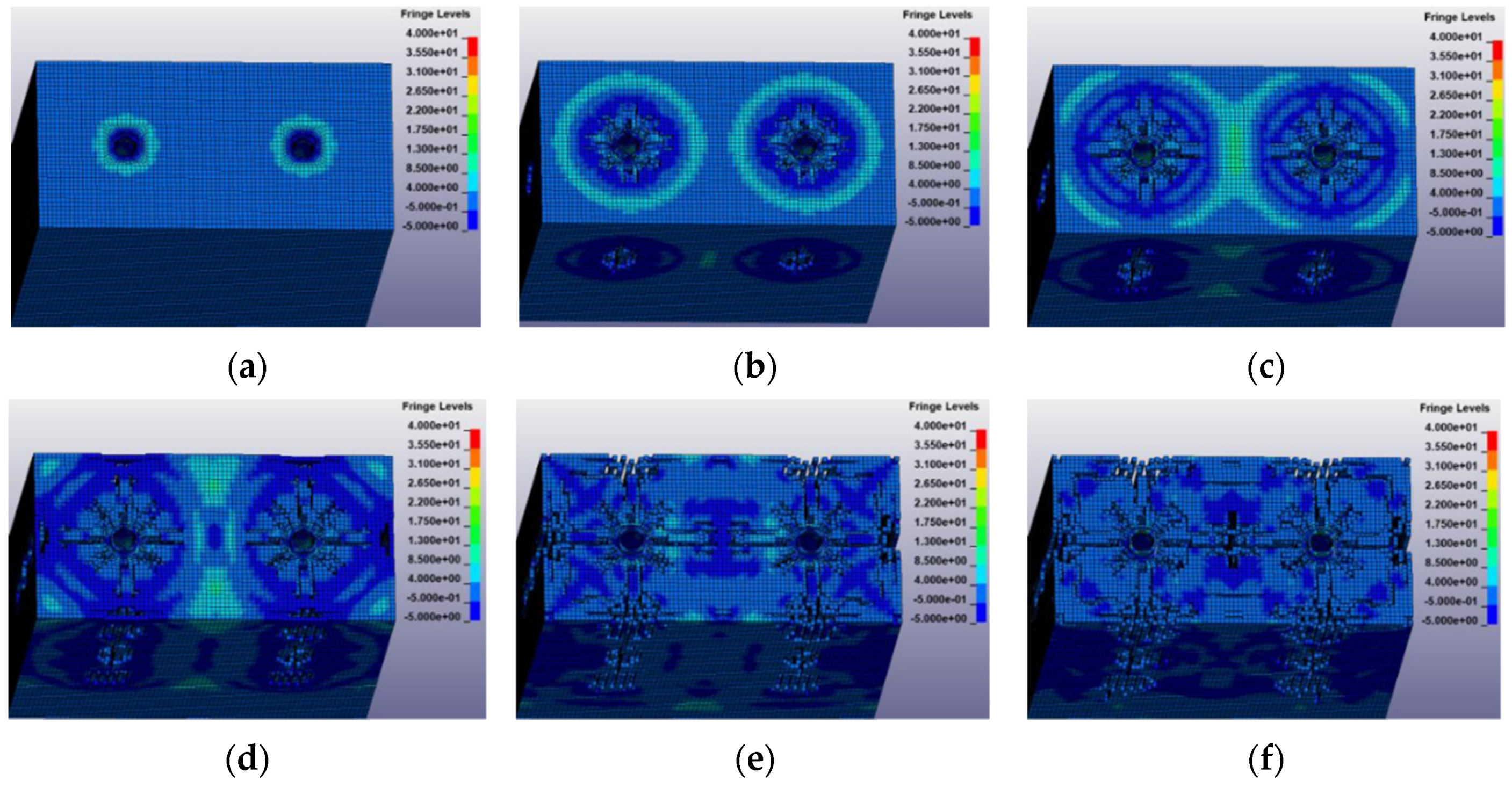
2.1.4. Simulation of a Concrete Beam Subjected to Impact Load

According to the symmetry of concrete members, a section of concrete beam along the length direction is taken as the finite element model analysis object, and only two holes adjacent to the left and right ends are reserved. The crack connectivity between adjacent holes in the actual beam and between the edge holes and the edge of the member is simulated by the two holes in the beam segment. The width of the concrete beam section is 400 mm, the height is 800 mm, and the length varies according to the hole spacing. The width of the concrete beam section is 400 mm, the height is 800 mm and the length is 600 mm. Two vertical boreholes are symmetrically arranged in the beam section and impact loads are applied. The whole process analysis results of the beam section are shown in Figure 1.
As shown in Figure 1, compressive stress is formed around each borehole and distributed in circumferential direction when the shock wave just touches concrete. After that, the range of compressive stress develops outwards with the propagation of shock wave, and the cracks first appear near the borehole and extend to all sides. When the shock wave propagates from the inside of the beam to the side of the beam, the circular distribution of compressive stress also appears on the side of the beam, after which the gradual increase of the compressive stress range also produces cracks on the side of the beam, and the cracks develop vertically on the side of the beam [28]. When the compressive stress range of the two boreholes increases gradually to overlap, the compressive stress of the two intersecting boreholes promotes the continuous development of cracks between the two boreholes until they are connected. When the distance between drilling and beam side and beam end is not large, cracks can extend to beam side and beam end, so that the beam is divided along the transverse and longitudinal.

2.2. Test of the Concrete Beam Broken by Pulse Power Discharge

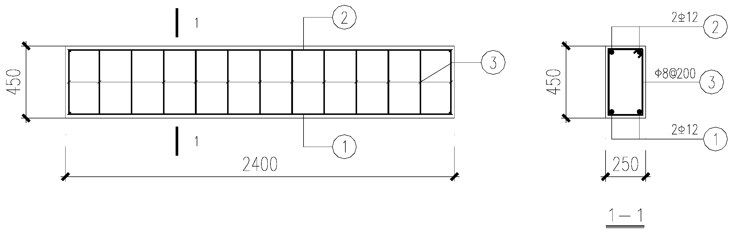
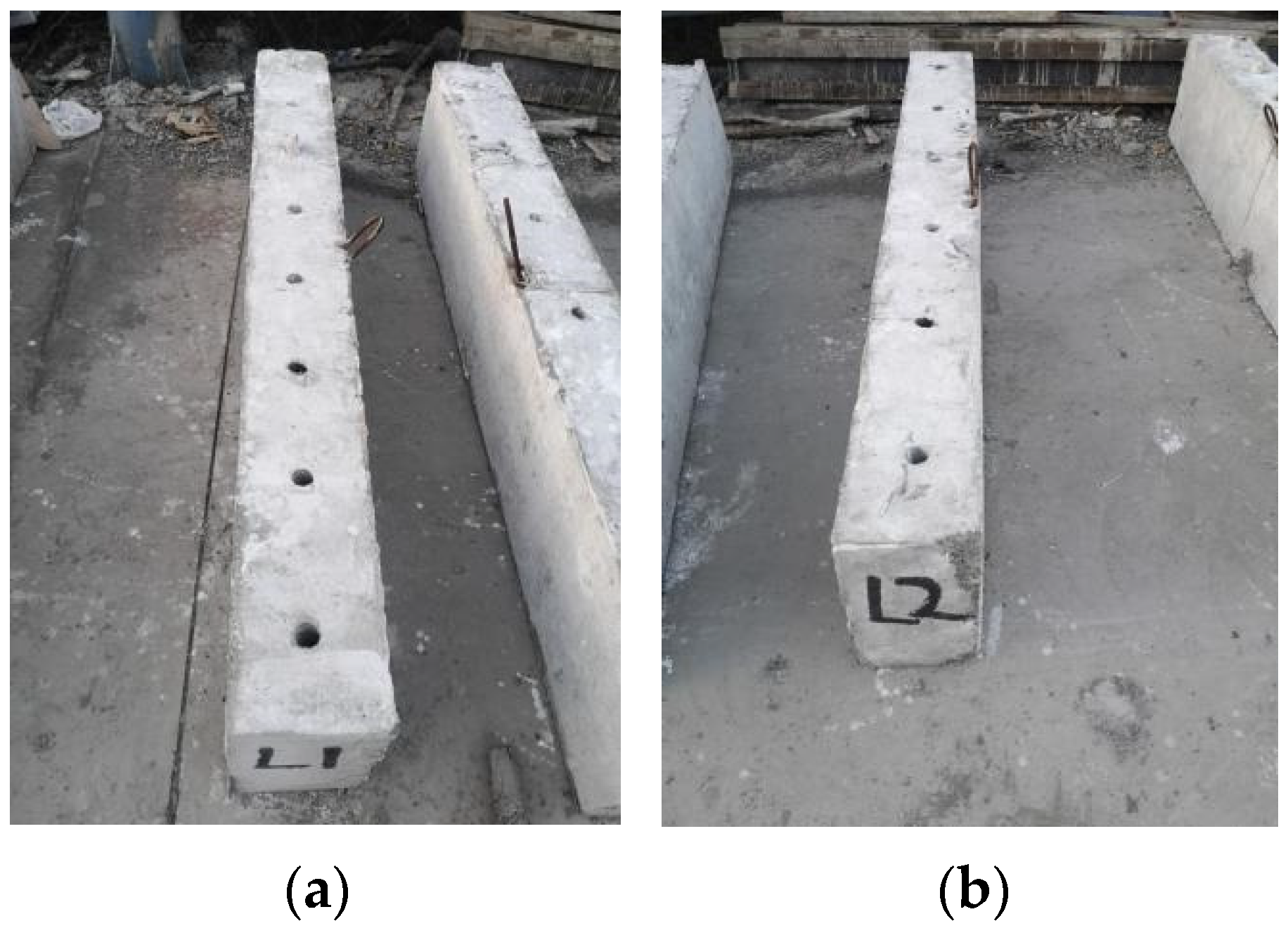
2.2.1. Specimen Design
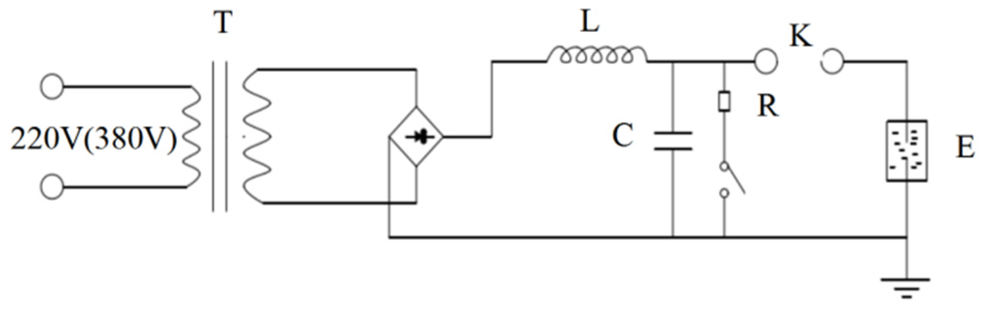
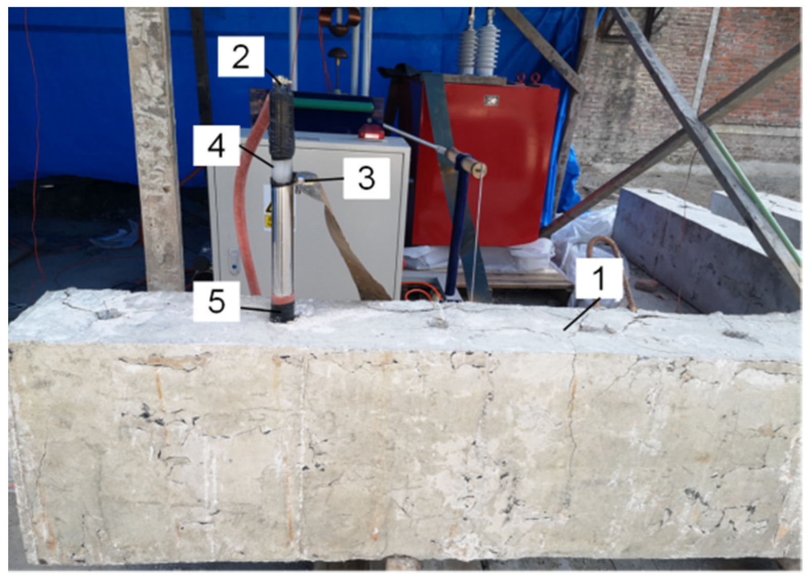
In order to study the influence of different parameters on the breaking effect of concrete beams, 15 reinforced concrete beams were designed and manufactured. The beam is 250 mm wide, 450 mm high and 2.4 m long. Two longitudinal deformed steel bars with diameter of 12 mm (tensile yield strength of 376.4 N/mm2, ultimate strength of 563.1 N/mm2) are arranged at the bottom and top of the beam, and the closed stirrups of φ8@200 are uniformly arranged along the whole length of the beam. The reinforcements of beams are shown in Figure 2. Holes were drilled vertically down on the top of the test beam, and the hole depth is 0.8 times the height of the beam, i.e., 360 mm. The drill holes are arranged in single row, with three kinds of spacing: 300 mm, 400 mm and 500 mm. Moreover, the aperture is divided into 40 mm and 50 mm. The corresponding variation parameters of test beams with different grades are shown in Table 2, where fcu is the cube compressive strength of concrete and fc is the prismatic compressive strength of concrete. The hole end distance refers to the distance from the beam end to the center of the nearest outermost hole. Moreover, the edge distance is the distance between the beam side edge and the center of each hole. Taking concrete L1 and L2 as examples, the spacing of drilling holes is 300 mm and 400 mm, respectively, as shown in Figure 3.

2.2.2. Test Method

Pulse power discharge crushing technology is still in the stage of theoretical and experimental research at present, there is no matching molding discharge equipment in the market, so this paper designed and manufactured an impulse current generator. To facilitate engineering applications, the device consists of three detachable parts:
  • Supercharging device: the ordinary 220 V voltage is converted into 0–100 kV high voltage through the transformer;
  • Energy storage device: this consists of a number of capacitors in series and in parallel to store charge;
  • Discharge device: this is composed of high and low voltage electrodes with a coaxial structure. The high voltage electrode is connected with the discharge device, and the low voltage electrode is connected with the grounding terminal.
The discharge process of impulse current generator can be simplified into R-L-C discharge circuit, as shown in Figure 4. Wherein, T is the booster device, R is the current limiting resistor, C is the energy storage capacitor, E is the discharge electrode, L is the inductor, and K is the gap switch.
The discharge test diagram of concrete beam is shown in Figure 5, where 1 is the concrete test beam with borehole, 2 is the high voltage end electrode, connected with the discharge equipment through the high voltage cable, 3 is the low voltage end electrode, connected with the grounding end through the copper skin, 4 is the insulating material between high and low voltage electrodes, and 5 is the plug on the top of the hole to prevent the liquid from splashing out after discharge. The specific process is as follows: fill the concrete beam with liquid (water), connect the high and low voltage electrical extremes with copper wire and insert it into the drilling hole, wrap the high voltage insulation rubber at the top of the drilling hole to prevent liquid splashing, and cover heavy objects. The device can charge and discharge automatically after adjusting and releasing the peak voltage through the console. The console can record current waveform and monitor residual voltage in real time. In order to prevent the capacitor from leaving residual power, it is necessary to contact the high voltage electrode with a conductive rod connected with the grounding terminal and the console shows that the residual voltage is 0 before manually touching the electrode for the next operation.
The discharge metal wires are copper wires with a length of 20 cm and a diameter of 0.2 mm, and the number of copper wires is 30, 40, 50, and 60, respectively. Although increasing the discharge voltage and energy can improve the crushing effect, it will greatly increase the cost, volume and weight of the equipment, which is not conducive to engineering applications. Therefore, this topic uses the concrete beam each hole 10 times discharge way to reduce the discharge voltage and single release of energy requirements. The discharge voltages are 40 kV, 50 kV, 60 kV, 70 kV, 80 kV, 90 kV, and 100 kV, respectively. The discharge voltage released by a certain hole in the test beams and the number of copper wires used are the same. However, the discharge voltage and the number of copper wires matched by different holes are different, so as to investigate the influence of discharge voltage and the total area of copper wire section on the breaking effect of concrete beams.

3. Results and Discussion

3.1. Results

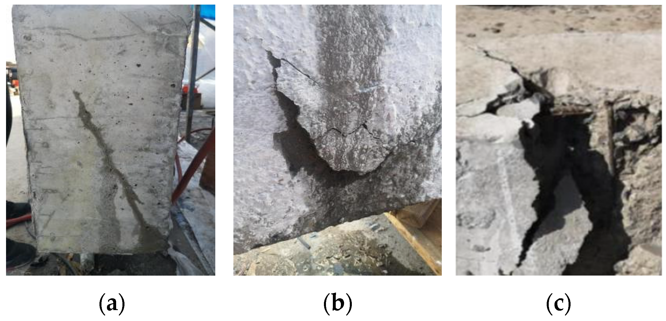
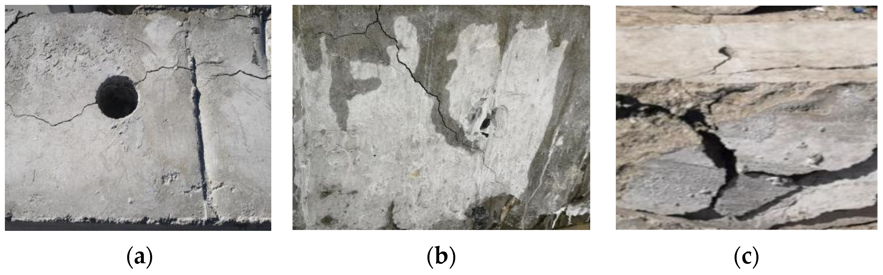
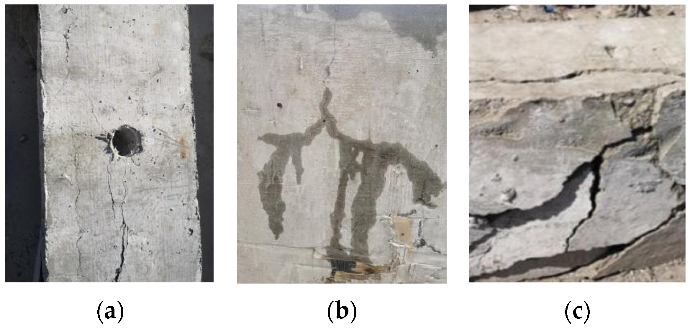
3.1.1. The Test Phenomenon

Taking the L1 beam as an example, the holes were numbered from left to right from 1 to 8, and the pulse discharge test was carried out one by one. For hole 1, 60 copper wires were used to connect high and low voltage electrodes to release 100 kV peak voltage. After a discharge, cracks appear near the borehole of the concrete beam, but the width is not large and the length is short, and there is a slight seepage phenomenon on the side of the beam. After the second discharge, the crack width gradually increases and extends around the hole. After the third discharge, the crack width of the concrete beam side continues to increase, the crack width has reached 4.2 mm, and the water seepage speed is accelerated. By this time, all the water has flowed out of the borehole. The plastic bag was filled with water and placed in the hole and inserted into the electrode for the fourth discharge. With the increase of discharge times, the crack width around the borehole and the concrete beam side continues to expand. When the 10th discharge is completed, the concrete protective layer on the side surface of the concrete beam disconnects, exposing the internal stirrups and longitudinal bars. The crushing effect is shown in Figure 6.
In hole 2, 50 copper wires were used to connect high and low voltage electrodes to release peak voltage of 80 kV. After the first discharge, fine cracks appear near the borehole and radially extend to the surrounding area, but the width of the cracks is smaller than that of hole 1. After the second discharge, obvious cracks appeared on the side surface of concrete beam accompanied by slight water seepage. After the fourth discharge, the crack width was further enlarged and the seepage rate was obviously accelerated. The plastic bag was filled with water and put into the hole and the electrode was inserted to continue discharging. With the increase of discharging times, the crack width continued to expand. Until the 10th discharge, the concrete protective layer partially disengaged, but the crack width near hole 2 was significantly smaller than hole 1. The crushing effect is shown in Figure 7.
Hole 3 was discharged and 60 copper wires were used to connect high and low voltage electrodes to release a peak voltage of 40 kV. After the first discharge, small cracks appeared near hole 3, and the width of the cracks was smaller than that of hole 2, extending radially to the adjacent holes. After the second discharge, the crack width near the borehole was obviously enlarged, and slight cracks appeared on the side surface of the concrete beam. After the fourth discharge, water seepage was obvious on the surface of the beam side, but the water seepage rate was slow. After continuing to discharge, the crack width continued to expand and the water seepage speed was obviously accelerated. After filling the plastic bag with water, the crack continued to discharge. After the 10th discharge, although the crack width increased, the concrete protective layer did not fall off, and the crack width was significantly smaller than that of hole 2. The breaking effect is shown in Figure 8.
The discharge test phenomenon of other concrete beams is similar to L1 beam. The crushing effect of concrete beams after 10 times of high voltage pulse discharge is shown in Figure 9. According to the test results of the concrete beam, the main characteristics of pulse power discharge breakage of the concrete beam are several longitudinal cracks along the surface of the beam side, most of the concrete protective layer falls off, and the steel bar and concrete peel off.

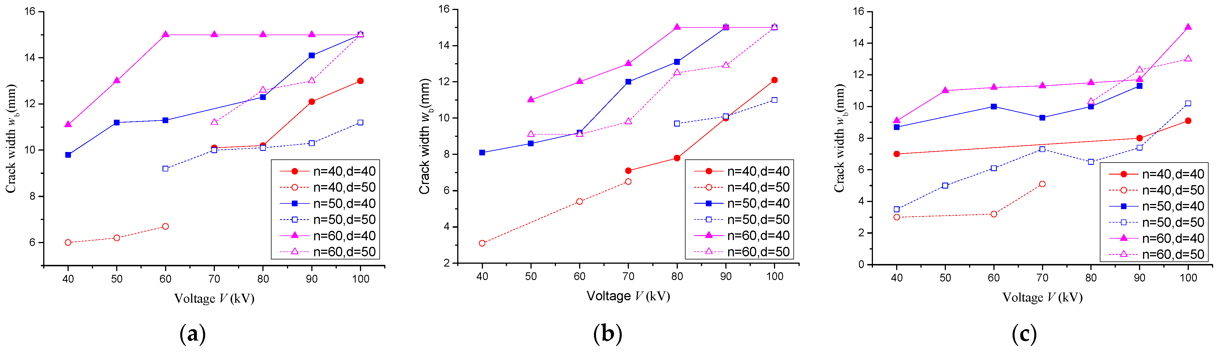
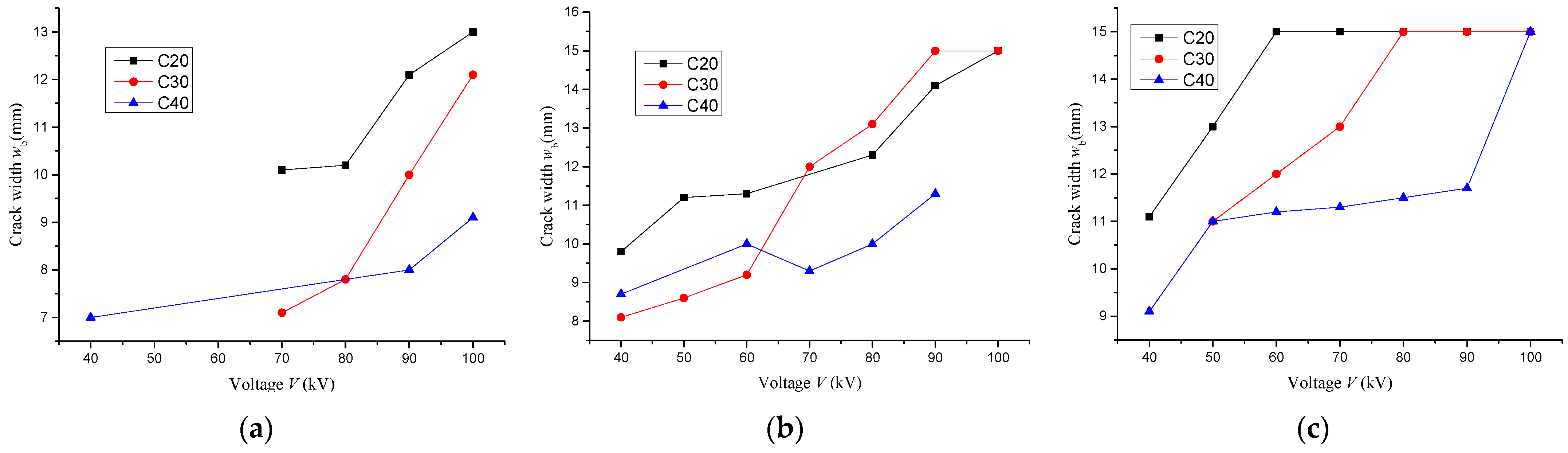
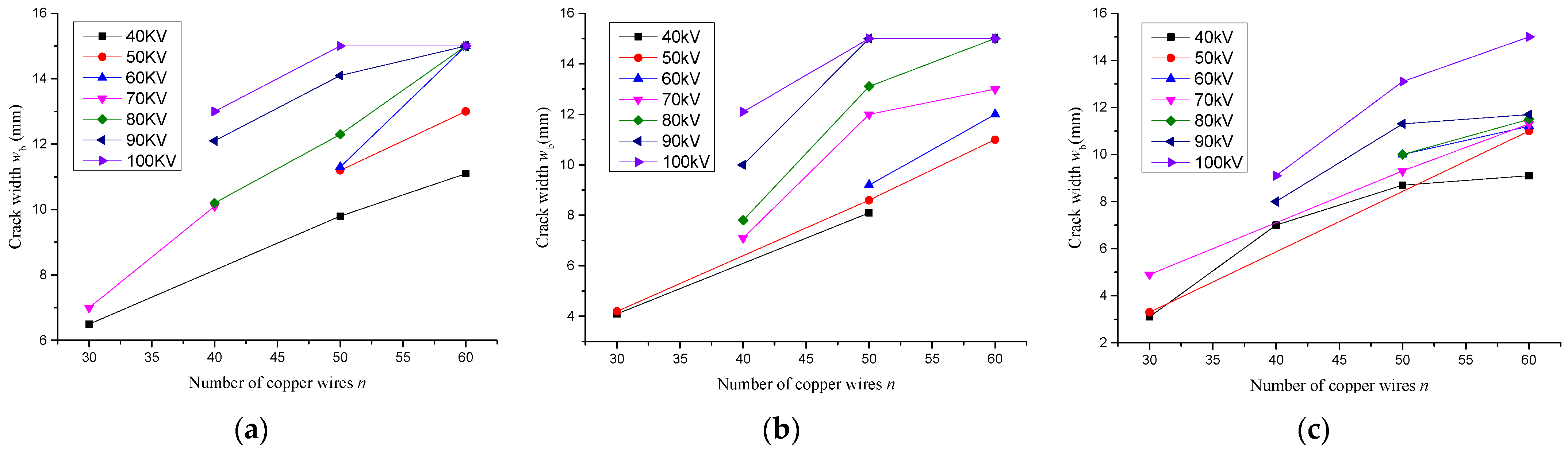
3.1.2. The Relation Curve between Different Parameters and Crack Width of Concrete

As shown in Figure 9, a number of irregular horizontal, oblique and vertical cracks were formed on the side of the concrete beams after high voltage pulse discharge. When the width of the concrete crack reached 15 mm, the protective layer of concrete beam side automatically fell off or light touch caused it to fall off. Therefore, when the protective layer of concrete beam side falls off, the crack width of this section is 15 mm. The relationship between the average crack width of concrete beams side along the vertical section of the hole and different influencing factors is discussed below.
  • Influence of hole diameter
In order to observe the influence of hole diameter on concrete crack width, the relationship between the crack width wb of beam side surface and the discharge voltage V under different concrete strength and the number of copper wires and hole diameter was plotted in Figure 9. The shape and color of the corresponding points of the same copper wire root number are the same, and solid points and hollow points are used to distinguish different holes. It can be seen from Figure 10a–c that under the same discharge voltage, number of copper wires, concrete strength and other parameters, the side crack width of concrete beams with a hole diameter of 40 mm is significantly higher than that of concrete beams with a hole diameter of 50 mm. There are two main reasons for this. One is that the smaller the hole diameter is, the better the sealing property of the inserted electrode is, the liquid in the hole is not easy to splash out, and the shock wave generated by the pulse power discharge can act on the concrete side wall more effectively. Second, the shock wave intensity will attenuate in the propagation process, so the smaller the pore diameter, the better the concrete side wall will bear the maximum impact load. Therefore, a 40 mm aperture is used as the suggested drilling aperture of concrete beam, and the influence of various parameters under 40 mm aperture on the crushing effect of concrete beam is discussed below.
2.
Influence of discharge voltage
The relation curve between average crack width wb and discharge voltage V of concrete beam side at the drilled section is shown in Figure 11. In Figure 11c, the crack width of the C20 concrete beam is 15 mm when the discharge voltage is above 60 kV, indicating that when the number of copper wires is 60, the discharge voltage of 60 kV can peel the concrete protective layer from the concrete beam. When parameters such as borehole aperture and concrete strength grade are the same, the increase of the discharge voltage can make the crack width increase greatly. This is because the discharge energy can be enhanced by increasing the discharge voltage, and thus, the energy of the shock wave can be increased.
3.
Influence of concrete strength
From Figure 11a, in the case of the same other parameters including the discharge voltage, when the number of copper wires is 40, the crack width of the C30 concrete beam is smaller than that of the C40 concrete beam under 70 kV discharge voltage, in other cases, the crack width decreases with the increase of concrete strength. When the number of copper wires is 50, the crack width of the C20 concrete beam is larger than that of the C40 concrete beam under the same condition. However, the crack width of C30 concrete is not obvious. When the discharge voltage is below 70 kV, the crack width is smaller than that of C40 concrete beam, while when the discharge voltage is greater than 70 kV, the crack width is larger than that of the C20 concrete beam. When the number of copper wires is 60, the rule is obvious, and the crack width decreases with the increase of concrete strength. Based on the above analysis, the crack width of the concrete beam increases slightly with the decrease of concrete strength.
4.
Influence of copper wire number
The relation curve between crack width wb and discharge voltage V on the side surface of concrete beam is shown in Figure 12. From Figure 12, under the same conditions of borehole diameter, concrete strength, discharge voltage, etc., the increase of the copper wire section area can promote the crack development of concrete beam. It shows that the increase of the total cross section area of copper wire increases the current flow of copper wire per unit time, thus enhancing the breaking effect of concrete beams.
5.
Influence of the spacing of boreholes
According to the test results, although the change of hole spacing has little influence on beam crack width, the smaller the hole spacing is, the more likely it is to form the connection of cracks between boreholes, so it is easier to peel off the concrete in the later treatment.

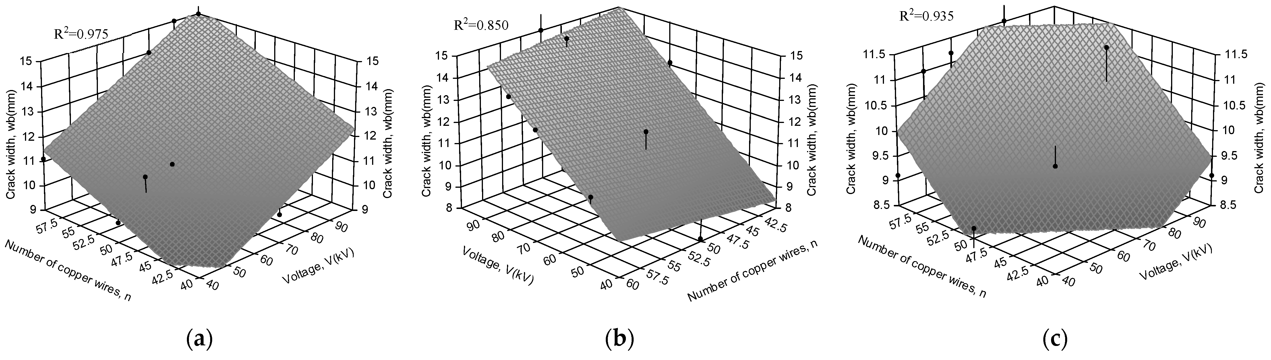
3.2. Expression of Breaking Effect

According to the above test results, three-dimensional fitting surfaces of crack width wb, number of copper wires n and discharge voltage V of the concrete beam side surface of concrete strength grade with hole diameter of 40 mm and hole spacing of 300 mm and 400 mm are formed, as shown in Figure 13 and Figure 14.
According to the fitting surface in Figure 13 and Figure 14, the breaking effect of concrete beams (i.e., the crack width wb on the side surface of concrete beams with the same section as drilling) is established as the objective function under the hole spacing of 300 mm and 400 mm with 40 mm aperture. Taking the number of copper wires n, discharge voltage V, concrete strength and other key parameters as independent variables, the mathematical calculation formulas are shown in Equations (3) and (4). Equation (3) is applicable to concrete beams with a hole diameter of 40 mm and a hole distance of 300 mm, and Equation (4) is applicable to concrete beams with a hole diameter of 40 mm and a hole distance of 400 mm.
w b = { 0.10 + 0.06 V + 0.15 n     C 20 4.59 + 0.08 V + 0.23 n     C 30 1.42 + 0.11 V + 0.06 n     C 40 }
w b = { 9.44 + 0.07 V + 0.30 n     C 20 1.88 + 0.05 V + 0.17 n     C 30 0.92 + 0.07 V + 0.12 n     C 40 }
From Figure 13 and Figure 14, the surface of the formula is close to the data point, and the coefficient of determination R2 of Equations (3) and (4) is above 0.85, indicating that the calculated value of the formula is in good agreement with the original data.

4. Recommendation

According to the above results, the following suggestions are put forward for concrete beam crushing engineering:
  • Multiple discharges such as 10 discharges are used to reduce the voltage required for a single discharge;
  • The discharge voltage of concrete with 20 MPa strength grade is 60 kV, and the number of copper wires is 60; the discharge voltage of concrete with 30 MPa strength grade is 80 kV, and the number of copper wires is 60; the discharge voltage of concrete with 30 MPa strength grade is 100 kV, and the number of copper wires is 60.
  • The drilling of the beam is 40 mm in diameter and 300 mm in spacing.

5. Conclusions

With the increase of the high voltage pulse discharge voltage and the increase of the number of copper wires, the breaking effect is greatly improved. Additionally, with the decrease of the concrete strength, the breaking effect is slightly improved.
When other parameters remain unchanged, the concrete beam with aperture of 40 mm has better breaking effect than the concrete beam with aperture of 50 mm. The reduction of hole spacing can make concrete cracks more easily connected and are easy to be broken and dismantled. However, it should be noted that too small hole spacing will increase the workload of drilling.
The mathematical expressions between the failure degree of concrete beam (i.e., the crack width of concrete side wb) and the output voltage V, the number of discharge copper wire n, the strength of concrete, the distance between drilling holes and other key parameters were established. The comparison between the calculation formulas and the test data shows that the calculation results of the crack width formulas in this paper are in good agreement with the test results.
The effects of drilling size, material strength, pulse power system and other key parameters on the crushing effect of concrete members were investigated, and the mathematical expression between the failure degree of concrete members and corresponding parameters was established, filling the research blank in this area. Some construction suggestions are put forward, which is helpful to the popularization and application of pulse power discharge technology in concrete structure crushing engineering.

Author Contributions

Conceptualization, X.W.; software, P.L.; data curation, Y.S.; formula analysis, W.W. All authors have read and agreed to the published version of the manuscript.

Funding

This research was funded by the National Key R&D Program of China, grant number 2017YFC0806100.

Institutional Review Board Statement

Not applicable.

Informed Consent Statement

Not applicable.

Data Availability Statement

Not applicable.

Conflicts of Interest

The authors declare no conflict of interest.

References

  1. Kozhevnikov, V.Y.; Kozyrev, A.V.; Semeniuk, N.S.; Kokovin, A.O. Theory of a High-Voltage Pulse Discharge in a High-Pressure Gas: Hydrodynamic and Kinetic Approaches. Russ. Phys. J. 2018, 61, 603–610. [Google Scholar] [CrossRef]
  2. Han, R.; Wu, J.; Zhou, H.; Zhang, Y.; Qiu, A.; Yan, J.; Ding, W.; Li, C.; Zhang, C.; Ouyang, J. Experiments on the characteristics of underwater electrical wire explosions for reservoir stimulation. Matter Radiat. Extremes 2020, 5, 24. [Google Scholar] [CrossRef]
  3. Owada, S.; Suzuki, R.; Kamata, Y.; Nakamura, T. Novel Pretreatment Process of Critical Metals Bearing E-Scrap by Using Electric Pulse Disintegration. J. Sustain. Met. 2018, 4, 157–162. [Google Scholar] [CrossRef]
  4. Biela, J.; Marxgut, C.; Bortis, D.; Kolar, J.W. Solid state modulator for plasma channel drilling. IEEE Trans. Dielectr. Electr. Insul. 2009, 16, 1093–1099. [Google Scholar] [CrossRef]
  5. Wielen, K.; Pascoe, R.; Weh, A.; Wall, F.; Rollinson, G. The influence of equipment settings and rock properties on high voltage breakage. Miner. Eng. 2013, 46-47, 100–111. [Google Scholar] [CrossRef]
  6. Yan, H.; Zhang, J.; Zhou, N.; Chen, J. The Enhancement of Lump Coal Percentage by High-Pressure Pulsed Hydraulic Fracturing for Sustainable Development of Coal Mines. Sustainability 2019, 11, 2731. [Google Scholar] [CrossRef] [Green Version]
  7. Jahami, A.; Temsah, Y.; Khatib, J.; Baalbaki, O.; Kenai, S. The behavior of CFRP strengthened RC beams subjected to blast loading. Mag. Civ. Eng. 2021, 103, 10309. [Google Scholar] [CrossRef]
  8. Temsah, Y.; Jahami, A.; Aouad, C. Silos structural response to blast loading. Eng. Struct. 2021, 243, 112671. [Google Scholar] [CrossRef]
  9. De, S.; Ranjith, P.G.; Perera, M.S.A.; Wu, B.; Rathnaweera, T.D. A modified, hydrophobic soundless cracking demolition agent for non-explosive demolition and fracturing applications. Process Saf. Environ. Prot. 2018, 119, 1–13. [Google Scholar] [CrossRef]
  10. Desirée, M.; Alba-Rodríguez, A.; Alejandro Martínez-Rocamora, B.; Patricia González-Vallejo, A.; Marrero, M. Building rehabilitation versus demolition and new construction: Economic and environmental assessment. Environ. Impact Asses. Rev. 2017, 66, 115–126. [Google Scholar] [CrossRef]
  11. Murakami, K.; Dosho, Y.; Uemura, K.; Kimura, H. Concrete Demolition and Surface Scraping using High Voltage Pulse Discharge. J. Adv. Concr. Technol. 2018, 16, 358–367. [Google Scholar] [CrossRef]
  12. Yudin, A.S.; Voitenko, N.V.; Kuznetsova, N.S. Two-Section Pulse Current Generator for Concrete and Rocks Destruction by Splitting Off. IEEE Trans. Plasma Sci. 2017, 45, 3042–3045. [Google Scholar] [CrossRef]
  13. Wang, X.; Zhu, J. Research and Applications of High-voltage Pulse Discharge Crushing. Eur. J. Electr. Eng. 2019, 21, 157–163. [Google Scholar] [CrossRef] [Green Version]
  14. Yan, G.; Zhang, Z.; Zhang, B.; Zhu, G.; Yao, H.; Zhu, X.; Han, J.; Liu, R.; Zhao, Y. Preferential sequence crushing of copper ore based upon high-voltage pulse technology. Miner. Eng. 2019, 131, 398–406. [Google Scholar] [CrossRef]
  15. Kuznetsova, N.S.; Lopatin, V.V.; Yudin, A.S. Effect of Electro-Discharge Circuit Parameters on the Destructive Action of Plasma Channel in Solid Media. J. Phys. Conf. 2014, 552, 012029. [Google Scholar] [CrossRef] [Green Version]
  16. Yudin, A.S.; Kuznetsova, N.S.; Bakeev, A.; Zhgun, D.V.; Stefanov, Y.P. Destruction of reinforced concrete by electric impulse discharges: Experiment and simulation. AIP Conf. Proc. 2017, 1909, 20234. [Google Scholar] [CrossRef]
  17. Koji, U.; Naoyuki, S.; Shintaro, S.; Yamachi, H.; Nakamori, J. Controlled disintegration of reinforced concrete blocks based on wave and fracture dynamics. Procedia Struct. Integr. 2016, 2, 350–357. [Google Scholar] [CrossRef] [Green Version]
  18. Lisitsyn, I.V.; Inoue, H.; Katsuki, S.; Akiyama, H.; Nishizawa, I. Drilling and Demolition of Rocks by Pulsed Power. In Proceedings of the 12th IEEE International Pulsed Power Conference, Monterey, CA, USA, 27–30 June 1999. [Google Scholar]
  19. Sun, X.; Ma, R.; Lv, J. Experimental Study on Crushing Rock Using High Voltage Pulse Power Technology. Chin. J. Undergr. Space Eng. 2020, 16, 1657–1664. [Google Scholar]
  20. Illias, H.A.; Tunio, M.A.; Mokhlis, H.; Chen, G.; Bakar, A.H.A. Experiment and modeling of void discharges within dielectric insulation material under impulse voltage. IEEE Trans. Dielectr. Electr. Insul. 2015, 22, 2252–2260. [Google Scholar] [CrossRef] [Green Version]
  21. Zuo, W.; Shi, F.; Manlapig, E. Modelling of high voltage pulse breakage of ores. Miner. Eng. 2015, 83, 168–174. [Google Scholar] [CrossRef]
  22. Yan, D.; Bian, D.C.; Ren, F.; Yin, Z.Q.; Zhao, J.C.; Niu, S.Q. Study on breakdown delay characteristics based on high-voltage pulse discharge in water with hydrostatic pressure. J. Power Technol. 2017, 97, 89–102. [Google Scholar]
  23. Yin, Z.Q.; Zhao, J.C.; Jia, S.H.; Bian, D.C.; Dong, Y. Experimental Study of Water Shock Load Characteristics Based on High-voltage Pulse Discharge. Coal Technol. 2016, 35, 182–185. [Google Scholar]
  24. Uenishi, K.; Yamachi, H.; Yamagami, K.; Sakamoto, R. Dynamic fragmentation of concrete using electric discharge impulses. Constr. Build. Mater. 2014, 67, 170–179. [Google Scholar] [CrossRef]
  25. Cho, S.H.; Cheong, S.S.; Yokota, M.; Kaneko, K. The Dynamic Fracture Process in Rocks Under High-Voltage Pulse Fragmentation. Rock Mech. Rock Eng. 2016, 49, 3841–3853. [Google Scholar] [CrossRef]
  26. Touya, G.; Reess, T.; Pécastaing, L.; Gibert, A.; Domens, P. Development of subsonic electrical discharges in water and measurements of the associated pressure waves. J. Phys. D Appl. Phys. 2006, 39, 5236–5244. [Google Scholar] [CrossRef]
  27. Catovic, A.; Kljuno, E. Comparation of Analytical Models and Review of Numerical Simulation Method for Blast Wave Overpressure Estimation after the Explosion. Adv. Sci. Technol. Eng. Syst. J. 2021, 6, 748–756. [Google Scholar] [CrossRef]
  28. Wang, X.; Li, N.; Du, J.; Wang, W. Concrete crushing based on the high-voltage pulse discharge technology. J. Build. Eng. 2021, 41, 102366. [Google Scholar] [CrossRef]
Figure 1. The simulation results of the concrete beam. (a) t = 55 μs; (b) t = 75 μs; (c) t = 85 μs; (d) t = 95 μs; (e) t = 120 μs; (f) t = 160 μs.
Buildings 12 00274 g001
Figure 2. Reinforcements of beams.
Buildings 12 00274 g002
Figure 3. Examples of beams with (a) 300 mm and (b) 400 mm hole spacing.
Buildings 12 00274 g003
Figure 4. Schematic diagram of the discharge device circuit.
Buildings 12 00274 g004
Figure 5. Pulse power breaking test of concrete beam.
Buildings 12 00274 g005
Figure 6. Breaking effect of Hole 1. (a) First discharge; (b) Fourth discharge; (c) Tenth discharge.
Buildings 12 00274 g006
Figure 7. Breaking effect of Hole 2. (a) First discharge; (b) Fourth discharge; (c) Tenth discharge.
Buildings 12 00274 g007
Figure 8. Breaking effect of Hole 3. (a) First discharge; (b) Fourth discharge; (c) Tenth discharge.
Buildings 12 00274 g008
Figure 9. Breaking effect of Hole 1. (a) Beam L1; (b) Beam L2; (c) Beam L3; (d) Beam L4; (e) Beam L5; (f) Beam L6; (g) Beam L7; (h) Beam L8; (i) Beam L9; (j) Beam L10; (k) Beam L11; (l) Beam L12; (m) Beam L13; (n) Beam L14; (o) Beam L15.
Buildings 12 00274 g009
Figure 10. The relationship between crack width and hole diameter. (a) Concrete C20; (b) Concrete C30; (c) Concrete C40.
Buildings 12 00274 g010
Figure 11. Relationship between crack width wb and discharge voltage V. (a) 40 copper wires; (b) 50 copper wires; (c) 60 copper wires.
Buildings 12 00274 g011
Figure 12. Relationship between crack width wb and number of copper wires n. (a) Concrete C20; (b) Concrete C30; (c) Concrete C40.
Buildings 12 00274 g012
Figure 13. Fitting surface of concrete crack width with copper wire number and discharge voltage at 300 mm hole spacing. (a) Concrete C20; (b) Concrete C30; (c) Concrete C40.
Buildings 12 00274 g013
Figure 14. Fitting surface of concrete crack width with copper wire number and discharge voltage at 400 mm hole spacing.
Buildings 12 00274 g014
Table 1. Physical and mechanical parameters of concrete.
Compressive Strength
fcu (N/mm2)
Tensile Strength
fc (N/mm2)
Density
ρ (g/mm3)
Modulus of Elasticity
E (N/mm2)
40.03.82.32 × 1093.4 × 104
Table 2. Main design parameters of the specimens.
Beam Labelfcu
(N/mm2)
fc
(N/mm2)
Aperture (mm)Hole Spacing (mm)End Distance (mm)Edge Distance (mm)
L-134.626.140300150125
L-234.626.140400200125
L-334.626.150300150125
L-444.330.950400200125
L-525.619.540300150125
L-625.619.540400200125
L-734.626.150300150125
L-825.619.550400200125
L-944.330.940300150125
L-1044.330.940400200125
L-1125.619.550300150125
L-1244.330.950400200125
L-1325.619.540500200125
L-1434.626.140500200125
L-1544.330.940500200125
Publisher’s Note: MDPI stays neutral with regard to jurisdictional claims in published maps and institutional affiliations.

