Abstract
Since reinforced concrete (RC) buildings have long service life, cutout openings are generally needed in their load-bearing walls as a sustainable solution in order to meet new requirements of their users. However, the cutout openings decrease the load-bearing capacity of the walls, which may result in the failure of the buildings. In this paper, we investigate the possibility of making a door opening in a load-bearing RC wall of an existing building in Gävle in Sweden. The wall studied in the current paper rests on two individual supports at its two ends; thus, it is considered as a deep beam. However, it is called an examined wall (EW) here. The StruSoft FEM-Design software is used in this study to model, analyze, and design the building based on the Eurocodes and Swedish national annex. The potential need for the EW to be strengthened when the cutout opening is made is also evaluated. It is concluded that strengthening the EW with cutout opening is needed. Different strengthening solutions are proposed for the EW. Moreover, the situation of the EW with the solutions is assessed with regard to the utilization ratio, deflection, and weight. Consequently, it is demonstrated that the proposed strengthening solutions function well for the EW.
Keywords:
reinforced concrete; wall; steel; deep beam; cutout opening; strengthening; utilization ratio; weight 1. Introduction
Long service life of reinforced concrete (RC) buildings can mean the buildings are still of good quality when the society has other demands on their use and configuration. An alternative to demolishing these buildings is to renovate them. Renovation is a more sustainable alternative to demolishing and building new, and it is sustainability that many actors strive for in the today’s society. In some cases, a few changes are enough for the buildings to be usable again; these can be, among other things, moving and tearing down walls or making openings of various kinds. Sometimes, making openings is enough and can be feasible for the walls. This implies that cutout openings must be created to meet the needs of the society, as it is not sustainable to demolish and rebuild.
However, making a cutout opening in a load-bearing RC wall is not without problems. When the reinforcements in the concrete of a load-bearing RC wall are cut and its concrete volume is reduced due to the opening, the load-bearing capacity of the wall is decreased, which means that cracks can occur and may result in the failure of the building’s structure.
When an opening is created in a wall subjected to loads, the wall will react differently depending on how it is supported. For a wall that is supported at the top and bottom, the bending takes place in one-way action (OW), as shown in Figure 1a. For a wall that is supported on all four sides, the bending takes place in two-way action (TW), as illustrated in Figure 1b [1,2]. In the OW, the wall usually bends according to a vertical curvature occurred in the middle of the wall. The cracks that may form are shown as horizontal lines approximately in the middle of the wall. This is also where the wall then fails. In the TW, the wall bends after two curvatures occurred in the horizontal and vertical directions. The cracks in this case become small and form from the edges of the opening toward the edges of the wall [3]. An experiment performed in [4] revealed that the axial capacity was changed when the opening area was changed in walls with the OW and TW. By increasing the length and width separately, the axial capacity of the walls was decreased. The most critical effect was obtained by the increase of the width and length simultaneously.
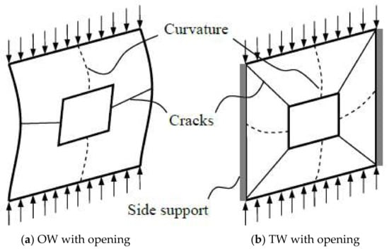
Figure 1.
Response of walls having opening with respect to boundary conditions.
To avoid the failure of the structure owing to the cutout opening in the wall, a detailed study on the structure and accurate control calculations must be performed. After the controls, it may turn out that the wall cannot withstand the loads due to the cutout opening or the wall with the cutout opening can carry the loads. In the former case, it may also be possible to find out that the wall can bear the loads if it is strengthened. In this case, the opening is allowed to be made in the wall after it is clarified that the building’s function is not endangered because of the opening.
If the clear span of a beam is less than four times its overall depth, it is classified as a deep beam [5]. Considering the above-mentioned explanations regarding the need of creating cutout openings in the load-bearing RC walls or deep beams, predicting the performance of these main structural elements with the cutout openings is important [6].
The possibility of making an opening for a door in a load-bearing RC wall of an existing building located in Gävle in Sweden is assessed in this paper. An opening with the dimensions of 1.01 × 2.11 m was needed for an RC wall with the dimensions of 7.04 × 3.73 m of the building, which was a project of a consulting company (Byggkonstruktören AB, Gävle, Sweden). The wall behaves like a beam since it has two individual supports at its end edges, and with regard to the prementioned definition of deep beams, the wall is a deep beam; however, it is called an examined wall (EW) in this paper.
Since creating openings in walls may make some changes in the stress distribution within the walls, they can adversely influence the performance of the walls. The web openings in RC beams can be classified as small and large openings [7]. There is a clear delimitation between small and large openings. The opening could be considered small if the ratio of the opening depth to the overall depth of the section were less than 25%. Otherwise, the opening could be taken into account as large [8]. Although the effects of small openings can often be neglected, the existence of large openings usually has considerably negative effects on the structural system [8,9]. In the current research, since this ratio is more than 25%, the opening is considered large, accordingly, the possibility of degradation in the load-bearing capacity of the structure owing to the presence of the opening is high.
Several research investigations have been carried out on RC walls with openings [1,3,4,8,10,11,12,13,14]. Some researchers have also evaluated strengthening methods of RC walls with openings using composites [2,15,16,17]. Moreover, RC deep beams with openings and with or without strengthening solutions have been examined [5,6,18,19,20,21,22], whereas an RC deep beam with and without cutout opening of an existing building is studied in this research work and various steel strengthening solutions are proposed for it as well.
This study is done by employing the StruSoft FEM-Design software. Modeling, analysis, and design of the building were conducted using the software based on the Eurocodes (EC0) [23], 1 (EC1) [24], 2 (EC2) [25], and 3 (EC3) [26] as well as the Swedish national annex (EKS10) [27]. The building is currently utilized as a school for grades 1–6. The school is large with several buildings sitting together. This building is a part of the school. The EW is controlled before and after creating the cutout opening. In addition, five different strengthening solutions are proposed and applied to the EW with the opening.
2. Method
The research has been carried out using the StruSoft FEM-Design software (2019) as one of the most used calculation programs for modeling, analysis, and design of simple to complex structures. The method of utilizing this software works well to solve these types of problems. The software takes how the building performs and how its different structural elements behave and affect each other under the applied loads and many load combinations into account. Accurate results can be accomplished by modeling the building carefully and completely.
2.1. Reference Building
The building has one basement and three stories, one of which is the attic. The plans of the building are displayed in Figure 2, Figure 3, Figure 4 and Figure 5.
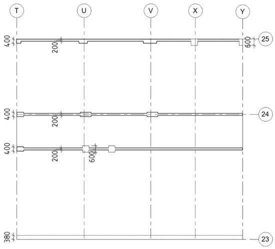
Figure 2.
Basement plan (unit: mm).
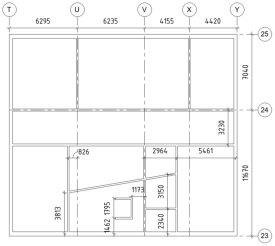
Figure 3.
Plan of story 1 (unit: mm).
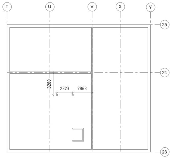
Figure 4.
Plan of story 2 (unit: mm).
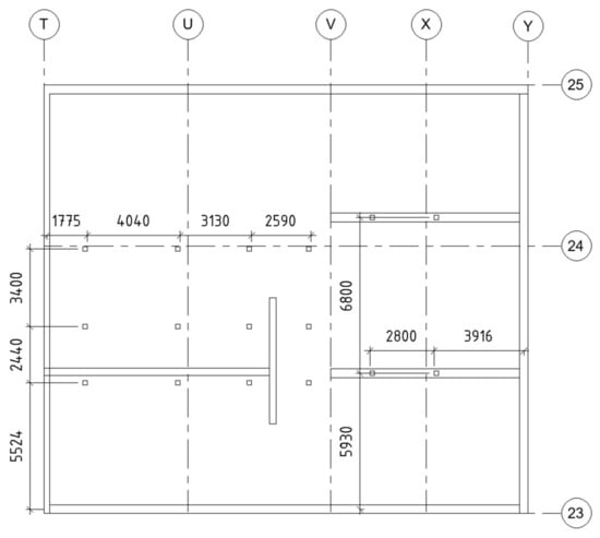
Figure 5.
Plan of attic (unit: mm).
2.2. Modeling, Analysis, and Design of Building
Table 1 lists specifications of the building’s stories, which have been considered in the modeling. The properties of the load-bearing elements of the building are summarized in Table 2. The location of each load-bearing element of the modeled building is demonstrated in Figure 6, Figure 7, Figure 8, Figure 9 and Figure 10. Plan of the basement floor and walls is illustrated in Figure 6, in which P1 is the RC slab and W1 & W2 are load-bearing RC walls. Figure 7 depicts the floor, which is located under the EW. P2, IV1–IV7, YV1, and AV1 & AV2 are the RC slab, load-bearing RC walls, brick wall, and steel headers and studs, respectively. Figure 8 clarifies the floor, where the EW is located on axis V between axes 24 and 25 with the indicated cutout opening. In this figure, P3, IV4 & IV5, IV8 & IV9 & YV1, B1, B2, and C2 & C3 are the RC slab, load-bearing RC walls, brick walls, RC beam, steel beam, and steel columns, respectively. The attic is the story above the EW, as displayed in Figure 9. P4, YV2, B3, B4 & B5, B6, C4, C5, and AV3 are the RC slab, brick wall, steel beam, RC beams, timber beam, steel column, timber column, and steel header, respectively. In Figure 10, all timber beams along Y and X directions are B7 and B8, respectively, while all the timber boards between the rafters are P5.

Table 1.
Specifications of stories of building.
Table 2.
Properties of elements of building.
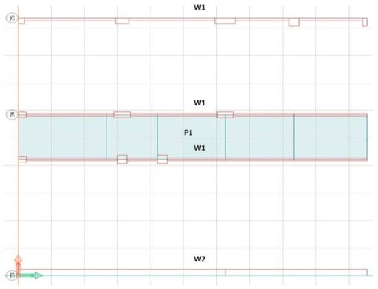
Figure 6.
Floor plan of basement with named load-bearing elements.
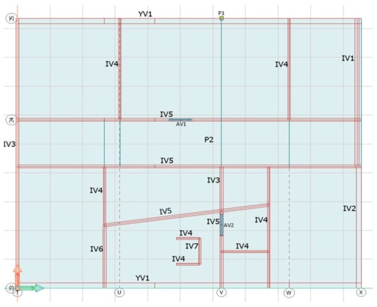
Figure 7.
Floor plan of story 1 with named load-bearing elements.
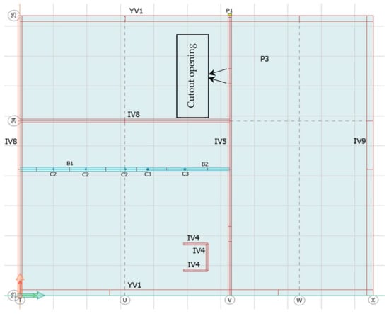
Figure 8.
Floor plan of story 2 with named load-bearing elements.
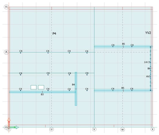
Figure 9.
Floor plan of attic with named load-bearing elements.
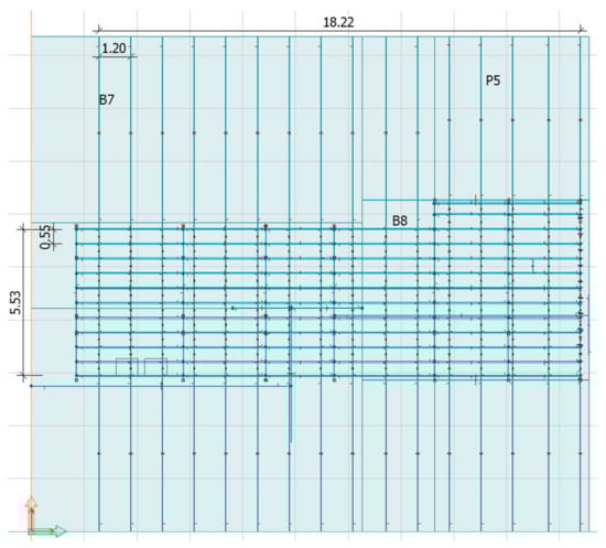
Figure 10.
Roof plan with named load-bearing elements (unit: m).
The software used beam, wall, and solid elements for modeling the beams, walls, and slabs of the building, respectively. The material models of the concrete and reinforcement are shown in Figure 11 and Figure 12, respectively. In Figure 11, the stress–strain curve for the concrete in compression is approximately linearly elastic up to about 40 percent of the mean value of the cylinder compressive strength (fcm). Then, the stress increases gradually up to fcm. Afterward, the curve descends into a softening region, and failure occurs at the ultimate compressive strain (εcu1). However, the stress–strain curve for the concrete in tension (Figure 11) is linearly elastic up to the tensile strength (ft). After that, the concrete cracks and its strength reduces linearly to 0.01 [28,29,30]. The ultimate limit states and the serviceability limit states have been applied. The ultimate limit states are associated with the collapse or other similar forms of structural failure. They generally correspond to the maximum load-bearing resistance of a structure or structural member. However, the serviceability limit states correspond to conditions beyond which specified service requirements for a structure or structural member are no longer met. For the reinforcement in Figure 12, graph B with the horizontal line was considered for the ultimate limit states and the same graph without safety factors was adopted for the serviceability limit states [31].
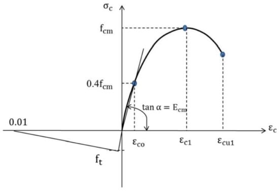
Figure 11.
Stress–strain relation for concrete.
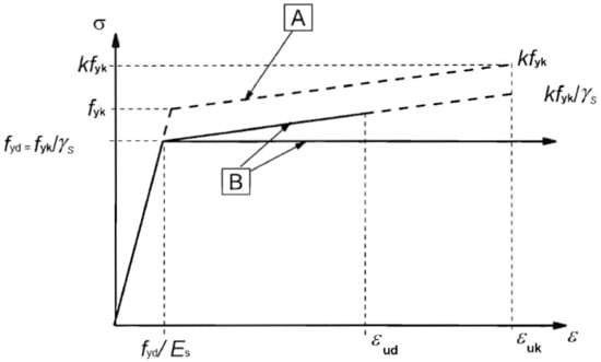
Figure 12.
Stress–strain relation for reinforcement.
Based on the EC2 [25] and EKS10 [27], characteristics of the concrete considered in Figure 11 are given in Table 3.
Table 3.
Characteristics of concrete in Figure 11.
In Figure 12, properties of the reinforcement are indicated in Table 4 in accordance with the EC2 [25] and EKS10 [27]. ftk in the table is the characteristic tensile strength of the reinforcement.
Table 4.
Properties of reinforcement in Figure 12.
The point support was used for the support of the columns, which is a point-like elastic support element with six degrees of freedom. The line support was utilized for the support of the walls that is a spatial, line-aligned, elastic support element with six degrees of freedom per node. This element is isoparametric and has three nodes in order to fit the surface elements. The boundary conditions of the reinforced concrete and brick elements were chosen as fixed, while those of the timber and steel elements were set to be hinged. The supports of all the load-bearing walls in the basement were considered as fixed.
Loads for the building were self-weight, imposed, snow, and wind. Load groups of permanent and temporary were assigned to the dead load and other loads of the building, respectively. Every load group contained one or more of earlier defined load cases. Depending on the EKS10 [27], different partial safety factors were defined. The building was loaded with its different kinds of loads based on the EC0 [23], EC1 [24], and EKS10 [27]. Table 5 summarizes the loads. Snow load and reference wind speed were considered according to the location of the building. The wind load was generated by the software on the basis of the reference wind speed of 23 m/s and terrain type III and was applied to the building. The program then automatically combined and calculated every possible load combination to find the most unfavorable load position for the variable loads. Load groups defined as permanent could be present in all the load combinations, and if a load group contained more than one load case, they would never be simultaneously present. Considering all the defined load groups, the load combinations were created in the ultimate limit state and serviceability limit state. The loads of each story were transferred to their lower story through secondary structural elements to primary elements depending on their stiffness.
Table 5.
Loads of building.
All the elements of the building such as beams, columns, walls, and floors were first modeled in the software. Next, material properties and cross-sections of the modeled elements of the building were defined. Then, the prepared model of the building was analyzed. All the load-bearing elements including steel, RC, and timber were designed and checked so that they could handle the loads having utilization ratios below 100%. The utilization ratio of each structural element is the ratio of the loads applied to the element to its load-bearing capacity. The utilization ratio must be less than 100% for the element to be able to carry the applied loads without failure.
In the software, the RC slabs (floors) were designed with respect to design moments on the basis of design forces. The design forces are the forces that the reinforcements should be designed for in the reinforcement’s directions. The necessary reinforcement calculations were performed using the design forces. The way of calculating the design forces is common in all modules and standards. In the software, the calculation of the design forces is based on the mechanism of the optimal reinforcement calculation for skew reinforcements. In order to minimize cracking in the slab, a good way is to reinforce according to the elastic moments, which normally also leads to good reinforcement economy. The required bending reinforcement was designed in accordance with the EC2 [25], where a rectangular stress distribution has been assumed (Figure 13).
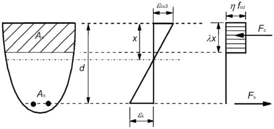
Figure 13.
Strain and stress distribution in RC.
In Figure 13, λ, and η are:
λ = 0.8 for fck ≤ 50 MPa
λ = 0.8 − (fck − 50)/400 for 50 < fck ≤ 90 MPa
and
η = 1 for fck ≤ 50 MPa
η = 1 − (fck − 50)/200 for 50 < fck ≤ 90 MPa
The finally considered properties of the elements of the building based on the analysis and design are listed in Table 2. The reinforcements of the RC slabs P1–P4 and load-bearing RC walls IV1 & IV4 & IV6 & IV7 were obtained as ϕ10@150. However, the reinforcements of the load-bearing RC walls IV2 and IV3 & IV5 were achieved as ϕ10@200 and ϕ10@300, respectively.
Figure 14 demonstrates the three-dimensional (3D) view of the modeled building. Figure 15 illustrates the building with a section in axis V to elaborate how the area around the EW looks like. The EW is marked with a red frame in the second story (under attic) between axes 24 and 25 with the dimensions of 7.04 × 3.73 m.
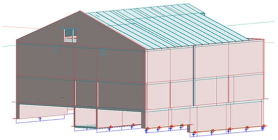
Figure 14.
3D view of the modeled building.
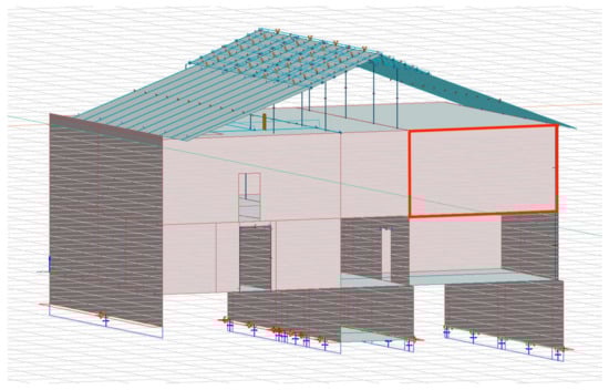
Figure 15.
Building with section in axis V showing EW.
3. Results and Discussion
Once modeling of all the building’s elements was completely done, the analysis of the building was carried out. Design of all the building’s elements was then conducted. Finally, the results were taken as the outputs. This section presents and discusses the results obtained from the analysis and design.
3.1. EW before and after Cutout Opening
From the result of the analysis, the utilization ratio of the EW before cutout opening was obtained 97% and acceptable, while its contour configuration can be seen in Figure 16. The yellow parts of the EW in Figure 16 reveal higher utilization ratios than its green parts.

Figure 16.
Utilization ratio of EW in contour before cutout opening.
An opening with the dimensions of 1.01 × 2.11 m was then created in the wall in the second story (under attic) between axes 24 and 25 (Figure 17). The utilization ratio of the wall was increased to 223% due to the cutout opening, which was larger than 100% uncovering the incapability of the wall in withstanding the loads; therefore, the wall needed to be strengthened. The increase of the utilization ratio was because of the fact that reinforcements in the place of the opening were cut and discontinued from other parts of the wall, also, the concrete was cut out and reduced in the wall where the opening was made. These discontinuations of the reinforcements and concrete in the wall affected the integrity of the wall in the opening. As a consequence, the remaining reinforcements and concrete of the wall had to compensate for the tensile and compressive forces that the removed part of the wall previously withstood. Figure 18 elaborates the utilization ratio of the wall in contour after the cutout opening. The presence of the cutout opening in the wall led to the disturbance in the uniform pattern of stresses. The discontinuities in the stresses caused high stresses in the small region of the wall as stress concentration. The deflections of the wall before and after creating the cutout opening were acceptable and had a little difference.
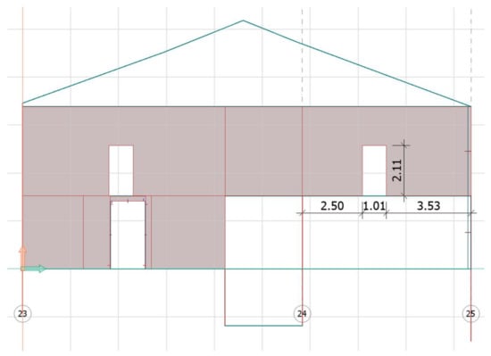
Figure 17.
EW after cutout opening in second story (under attic) between axes 24 and 25 (unit: m).
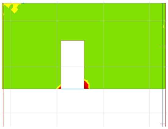
Figure 18.
Utilization ratio of EW in contour after cutout opening.
3.2. Proposed Strengthening Solutions for EW with Cutout Opening
Since the utilization ratio of the EW with the cutout opening was resulted larger than 100%, different strengthening solutions were proposed and assessed for the EW to investigate if the strengthened EW could carry the loads and function well. These proposed strengthening solutions (PSSs) would also be feasible in reality, which are introduced and discussed here. Table 6 describes the PSSs for the EW and summarizes the obtained results as the utilization ratios of the EW with the PSSs and the weight of each added PSS. Figure 19, Figure 20, Figure 21, Figure 22, Figure 23, Figure 24, Figure 25, Figure 26, Figure 27 and Figure 28 display how different PSSs were employed for the EW. The deflections of the EW with the cutout opening after adding each PSS were acceptable and close to each other. Thus, the utilization ratio of the EW and added weight owing to each PSS could be the determining factors for selecting the optimal PSS. The summarized results of Table 6 are also compared in Figure 29.
Table 6.
Summary of PSSs.
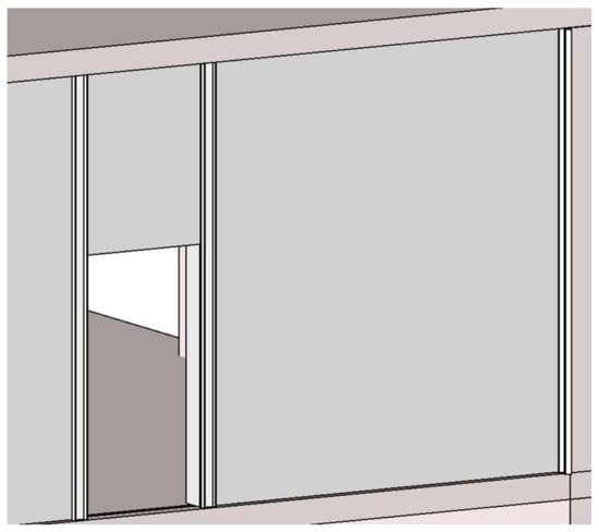
Figure 19.
PSS (U1).
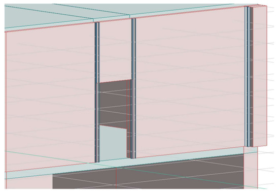
Figure 20.
Modeled PSS (U1).
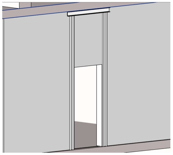
Figure 21.
PSS (U2).
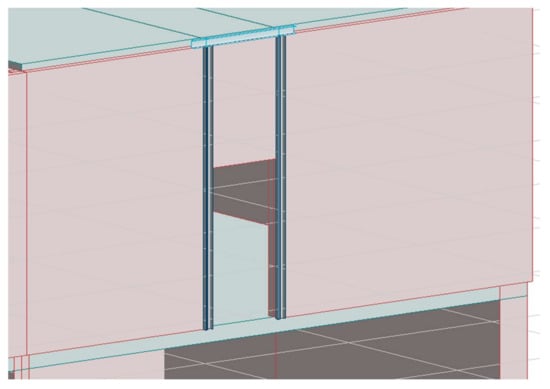
Figure 22.
Modeled PSS (U2).
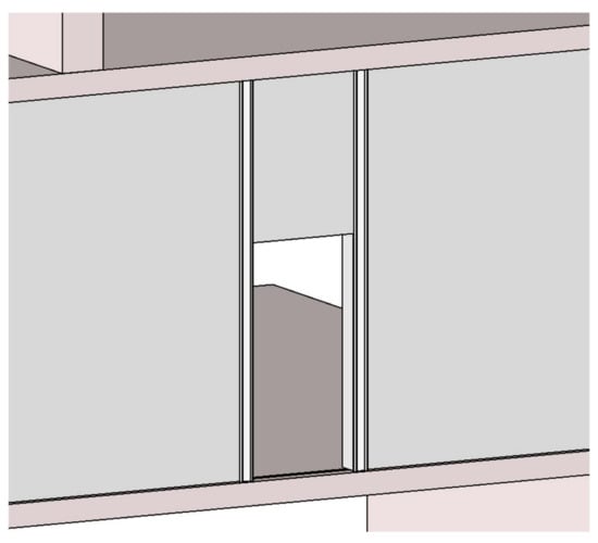
Figure 23.
PSS (U3).
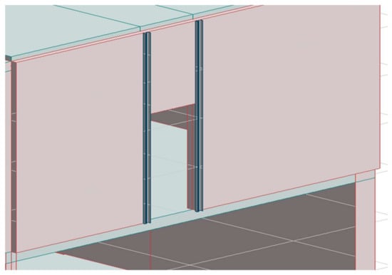
Figure 24.
Modeled PSS (U3).
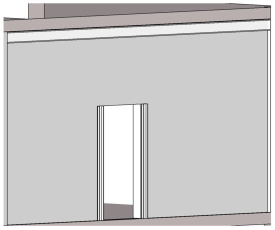
Figure 25.
PSS (H1).
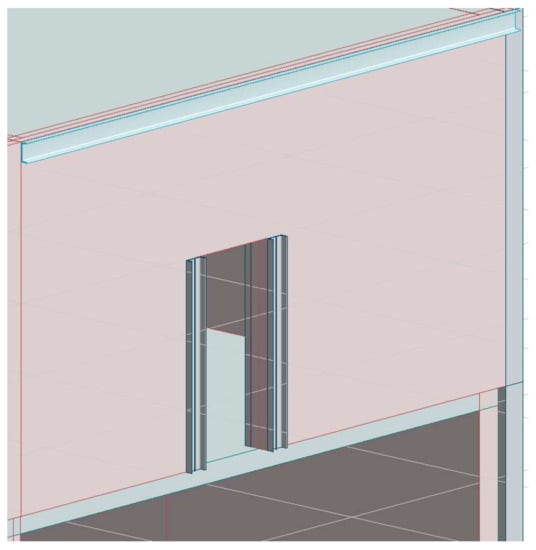
Figure 26.
Modeled PSS (H1).

Figure 27.
PSS (H2).
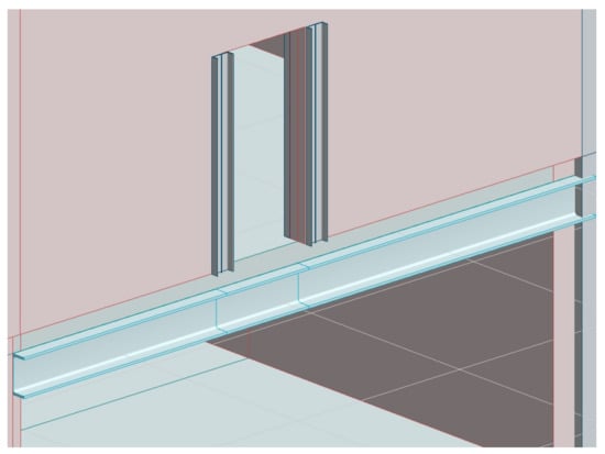
Figure 28.
Modeled PSS (H2).
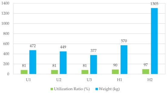
Figure 29.
Comparison of utilization ratios of EW having various PSSs and weight of PSSs.
Figure 29 clearly uncovers how the results of the EW with various PSSs are different. As it was mentioned earlier, these PSSs were adopted for the EW because the presence of the large opening in the wall caused a notable decrease in the load-bearing capacity of the wall, i.e., led to the utilization ratio of the wall to be larger than 100% as 223%. The PSSs for the EW with the opening enhanced the load-bearing capacity of the EW, i.e., decreased the utilization ratio of the wall to be below 100%. The figure depicts that the utilization ratios of the EW with all the PSSs were below 100% and acceptable. As it could be witnessed from Figure 19, Figure 20, Figure 21, Figure 22, Figure 23, Figure 24, Figure 25, Figure 26, Figure 27 and Figure 28 and Table 6, the PSSs were of varied design and weight of the steel, because it was to evaluate how they affect the EW. H1 and H2 had larger weights than other PSSs, whereas U3 possessed the lowest weight (377 kg). U1, U2, and U3 were the PSSs with the lowest utilization ratio (81%), while H1 and H2 owned the highest utilization ratios respectively as 90% and 97%. The same utilization ratio of U1, U2, and U3 revealed that a beam under the upper (attic) floor in U2 or a column attached to the exterior wall in U1 had no significant effect from the utilization ratio viewpoint. However, U2 had less weight than U1 but higher weight than U3. H1 and H2 were comparable, since the only difference between them was that the beam was placed under the upper floor (attic) in H1 and under the floor on level 2 (bottom floor) in H2, and also their beams had different dimensions and profiles.
Since ventilation pipes and other piping of buildings are often placed under their ceilings, the beams of the PSSs (H1 and H2), which were along the ceilings could entail additional costs for piping. It should also be taken into account that the story height of the bottom floor was affected with the beam of H2, which could lead to experiencing smaller space of the room. These were the problems that constructing H1 and H2 in the building might cause. However, H1 and H2 were considered because it might be easier to practically apply the PSSs in these ways in some cases. The results for H1 and H2 implied that H1 had lower utilization ratio than H2. This could be due to the point that H1 had the beam, which was placed under the attic floor, meaning the load was distributed toward the side walls and thus reduced the loads on the EW. Furthermore, H1 and H2 had greater utilization ratios than the U-proposals. This could be because the U-proposals transferred the load through the EW in a different way compared with the H-proposals, as the columns of the H-proposals did not go all the way up to the attic floor, while the columns of the U-proposals did. Generally, these PSSs helped the loads distribute on surrounding elements of the opening, and thus reduced the load within the area of the opening, which led to the successful pass of the loads around the opening.
Consequently, since the biggest difference between the PSSs was the weight of the steel and the utilization ratio, these should be accounted for selecting the optimal PSS. The lower utilization ratio means that the building could handle more loads; on the other hand, the lighter PSS signifies less imposed load from the PSS to the building, which is structurally favorable. Last, the steel production is a process that emits large quantities of greenhouse gases and it can be great to conclude lighter PSS for sustainable construction.
Considering the aforementioned explanations, U3 is the optimal PSS, having low utilization ratio and lowest weight as 81% and 377 kg, respectively.
Additionally, since the weight of the structure is a decisive factor for the building’s foundation and soil, with the consideration of the reduced weight of the EW as about 1023 kg due to the opening and the added weight of the optimal PSS (U3) as 377 kg, it can be concluded that no weight has finally been added to the building’s structure using the PSS. Therefore, adding the PSS to the wall did not increase the stresses in the building’s foundation and soil, which is absolutely favorable from the structural viewpoint.
4. Conclusions
Since a cutout opening was needed to be made in a load-bearing RC wall of an existing building, which behaved as a deep beam, this paper assessed its possibility with different conditions. This research was carried out using the StruSoft FEM-Design software in which the building and its structural elements were modeled, analyzed, and designed following the Eurocodes 0–3 and EKS10. When the opening was made in the EW, the utilization ratio of the wall became 223%, which elaborated the need for strengthening the EW. Five different strengthening solutions (U1, U2, U3, H1, and H2) were proposed for the EW with the cutout opening. The EW with the PSSs was thereafter evaluated with regard to the utilization ratio, deflection, and weight. The EW with the opening and using various PSSs resulted in the utilization ratios of 81–97%, which were acceptable. Their deflection had a small difference and thus did not influence the selection of the optimal solution. However, the steel weights of the PSSs had large differences and were in the range of 377–1305 kg. The finally selected PSS was U3 that had the lowest utilization ratio of 81% with U1 and U2 and lowest steel weight of 377 kg. The novelties of this research can be specified as (a) the EW of the RC building in the current paper behaved like a deep beam, which was a special case; (b) this research was a practical research, which was done on a real building; (c) the five different PSSs of this paper were special proposals, which were examined from various structural perspectives including the utilization ratio, deflection, and weight; and (d) owing to any practical reasons, if any presented PSSs of this study other than the optimal one are preferred to be utilized in other practical projects, it can perfectly be possible as well. This research work can be of interest to building constructors and consultants who might be doubtful whether cutting out an opening in load-bearing RC walls would be possible. This work can also be used as a guide in the design for practitioners making a cutout opening in load-bearing RC walls and applying PSSs by utilizing the StruSoft FEM-Design software.
Author Contributions
Conceptualization, A.B., F.Å. and K.K.; methodology, A.B., F.Å. and K.K.; investigation, A.B., F.Å. and K.K.; validation, A.B.; resources, A.B.; writing—original draft preparation, A.B.; writing—review and editing, A.B.; supervision, A.B. All authors have read and agreed to the published version of the manuscript.
Funding
This research received no external funding.
Data Availability Statement
Not applicable.
Conflicts of Interest
The authors declare no conflict of interest.
References
- Doh, J.H.; Fragomeni, S. Evaluation of experimental work on concrete walls in one and two-way action. Aust. J. Struct. Eng. 2005, 6, 37–52. [Google Scholar] [CrossRef]
- Hansen, C.S.; Sas, G.; Täljsten, B. FRP strengthening of RC walls with openings. In Advanced Composites in Construction 2009: Conference Proceedings, 1st ed.; ACIC: Chesterfield, UK, 2009; pp. 202–213. [Google Scholar]
- Doh, J.H.; Fragonemi, S. Ultimate load formula for reinforced concrete wall panels with openings. Adv. Struct. Eng. 2006, 9, 103–115. [Google Scholar] [CrossRef]
- Guana, H.; Cooper, C.; Lee, D.J. Ultimate strength analysis of normal and high strength concrete wall panels with varying opening configurations. Eng. Struct. 2010, 32, 1341–1355. [Google Scholar] [CrossRef]
- Khalaf, M.R.; Al-Ahmed, A.H.A. Shear strength of reinforced concrete deep beams with large openings strengthened by external prestressed strands. Structures 2020, 28, 1060–1076. [Google Scholar] [CrossRef]
- Kong, F.K.; Sharp, G.R. Structural idealization for deep beams with web openings. Mag. Concr. Res. 1977, 29, 81–91. [Google Scholar] [CrossRef]
- Mansur, M.A.; Tan, K.H. Concrete Beam with Opening Analysis and Design; CRC Press LLC: Boca Raton, FL, USA, 2019. [Google Scholar]
- Popescu, C.; Sas, G.; Blanksvärd, T.; Täljsten, B. Concrete walls weakened by openings as compression members: A review. Eng. Struct. 2015, 89, 172–190. [Google Scholar] [CrossRef][Green Version]
- Seddon, A.E. The strength of concrete walls under axial and eccentric loads. In Symposium on the Strength of Concrete Structures; Andrew, R.P., Ed.; Cement and Concrete Association: London, UK, 1956; pp. 445–486. [Google Scholar]
- Doh, J.H.; Loo, Y.C.; Fragomeni, S. Concrete walls with and without openings supported on three sides. In Conference on Incorporating Sustainable Practice in Mechanics of Structures and Materials; Griffith University: Brisbane, QS, Australia, 2011. [Google Scholar]
- Taleb, R.; Bechtoula, H.; Sakashita, M.; Kono, S.; Bourahla, N. Behaviour of Reinforced Concrete Walls with Different Opening Locations: Experiment and FEM Analysis. In Proceedings of the 15th World Conference on Earthquake Engineering, Lisbon, Portugal, 24–28 September 2012. [Google Scholar]
- Massone, M.L.; Muñoz, G.; Rojas, F. Experimental and numerical cyclic response of RC walls with openings. Eng. Struct. 2019, 178, 318–330. [Google Scholar] [CrossRef]
- Sabau, C.; Popescu, C.; Bagge, N.; Sas, G.; Blanksvärd, T.; Täljsten, B. Local and global behavior of walls with cut-out openings in multi-story reinforced concrete buildings. Eng. Struct. 2019, 187, 57–72. [Google Scholar] [CrossRef]
- Ou, Y.-C.; Hoang, L.; Roh, H. Cyclic behavior of squat reinforced concrete walls with openings typical of exterior walls of row houses in Taiwan. Eng. Struct. 2019, 195, 231–242. [Google Scholar] [CrossRef]
- Mohammed, B.S.; Ean, L.W.; Malek, M.A. One way RC wall panels with openings strengthened with CFRP. Constr. Build. Mater. 2013, 40, 575–583. [Google Scholar] [CrossRef]
- Popescu, C.; Sas, G.; Blanksvärd, T.; Täljsten, B. Concrete walls with cutout openings strengthened by FRP confinement. J. Compos. Constr. 2016, 21, 04016106. [Google Scholar] [CrossRef]
- Sabau, C.; Popescu, C.; Sas, G.; Blanksvärd, T.; Täljsten, B. Axially loaded RC walls with cutout openings strengthened with FRCM composites. J. Compos. Constr. 2018, 22, 1–16. [Google Scholar] [CrossRef]
- Yang, K.-H.; Eun, H.-C.; Chung, H.-S. The influence of web openings on the structural behavior of reinforced high-strength concrete deep beams. Eng. Struct. 2006, 28, 1825–1834. [Google Scholar] [CrossRef]
- Campione, G.; Minafò, G. Behaviour of concrete deep beams with openings and low shear span-to-depth ratio. Eng. Struct. 2012, 41, 294–306. [Google Scholar] [CrossRef]
- Mohamed, A.R.; Shoukry, M.S.; Saeed, J.M. Prediction of the behavior of reinforced concrete deep beams with web openings using the finite element method. Alex. Eng. J. 2014, 53, 329–339. [Google Scholar] [CrossRef]
- Jasim, W.A.; Abu Tahnat, Y.B.; Halahla, A.M. Behavior of reinforced concrete deep beam with web openings strengthened with (CFRP) sheet. Structures 2020, 26, 785–800. [Google Scholar] [CrossRef]
- Kumari, A.; Nayak, A.N. An experimental approach for strengthening of RC deep beams with web openings using GFRP fabrics and gas actuated fasteners. J. Build. Eng. 2021, 35, 102027. [Google Scholar] [CrossRef]
- EN 1990 (2002): Eurocode—Basis of Structural Design; European Committee for Standardization: Brussels, Belgium, 2010.
- EN 1991-1-1 (2002): Eurocode 1: Actions on Structures—Part 1-1: General Actions—Densities, Self-Weight, Imposed Loads for Buildings; European Committee for Standardization: Brussels, Belgium, 2011.
- EN 1992-1-1 (2005): Eurocode 2: Design of Concrete Structures—Part 1-1: General Rules and Rules for Buildings; European Committee for Standardization: Brussels, Belgium, 2008.
- EN 1993-1-1 (2005): Eurocode 3: Design of Steel Structures—Part 1-1: General Rules and Rules for Buildings; European Committee for Standardization: Brussels, Belgium, 2008.
- EKS 10: BFS 2015:6 (2015): Swedish National Annex for Application of Eurocodes; The National Board of Housing, Building and Planning: Karlskrona, Sweden, 2015.
- Bangash, M.Y.H. Concrete and Concrete Structures: Numerical Modelling and Applications; Elsevier Applied Science: London, UK; New York, NY, USA, 1989. [Google Scholar]
- Hind, M.K.; Özakça, M.; Ekmekyapar, T. A review on nonlinear finite element analysis of reinforced concrete beams retrofitted with fiber reinforced polymers. J. Adv. Res. Appl. Mech. 2016, 22, 13–48. [Google Scholar]
- Shamass, R.; Cashell, K.A. Behaviour of composite beams made using high strength steel. Structures 2017, 12, 88–101. [Google Scholar] [CrossRef]
- StruSoft. FEM-Design Applied Theory and Design; StruSoft: Malmö, Sweden, 2019. [Google Scholar]


Publisher’s Note: MDPI stays neutral with regard to jurisdictional claims in published maps and institutional affiliations. |
© 2021 by the authors. Licensee MDPI, Basel, Switzerland. This article is an open access article distributed under the terms and conditions of the Creative Commons Attribution (CC BY) license (https://creativecommons.org/licenses/by/4.0/).