1. Introduction
Due to the increasing number of high-rise building constructions, deep excavation is a popular method used to obtain underground space. This space can serve different purposes of the finished product such as car parking lots, cellars, shops, mechanical, electrical, and plumbing services [
1]. In the deep excavation work, the retaining wall and strutting system are designed and constructed to prevent the collapse of the excavated soil around the construction zone [
2,
3]. Moreover, deep excavation has become an important method in the construction of underground structures because it roughly costs around 20% of the total construction cost. When the scale and depth of the excavation work are increased with the building construction projects, many issues related to geological conditions, underground structures, and construction sites are carefully considered in the deep excavation process.
In the deep excavation process, the retaining wall, which is made of concrete or steel, is first placed around the excavation area. Then, the excavation work uses heavy equipment such as excavators and dump trucks to remove the first layer of the soil and install the strutting system. After the soil removal has reached the bottom level, the foundation structure is constructed and followed up with the underground structures such as pile, footing, girder, slab, column, and beam. In this process, the strutting system is one of the important structures use to brace the lateral force of the land in the deep excavation work [
4,
5].
Figure 1 shows components of the strutting system. With this system, the kingpost is the only vertical element that usually uses to support the structural strut [
6]. Moreover, this kingpost has to properly install to avoid the constructible problems that could cause damage, or collapse of the retaining structure and adjacent residents [
7].
Although the kingpost is an important element used to support the vertical direction of the strutting system, previous studies found kingpost problems at the construction site for the last decade. First, an inadequate connection of kingposts, which was one of four main problems in the deep excavation of Taiwan, contributed to the failure of lateral bracings [
8]. Next, inadequate installation problems of kingposts, which support the struts through the brackets, were incorrectly used to support the trestle [
3]. Then, any movement or vibration of the kingpost, which was produced by the heavy equipment, clearly affected the stability of the struts. Another research study found that space and physical conflicts of kingposts at the site were the main construction problems in Bangkok’s deep excavations [
9]. Besides these mentioned problems, clash problems of the kingpost still occurred and led to interruptions of the construction work at the site [
10]. After the structural strut was installed and excavation work done completely, the underground structure needed to be constructed consequently. During this stage, the engineers encountered the problem that the kingpost was clashed by the underground structures, such as (1) kingpost and pile, (2) kingpost and footing, and (3) kingpost and column [
8]. Then, they had to cut the kingpost to install the underground structure. The remaining kingpost was kept in the underground structures, such as footing. Due to the constructible problems, especially clashes between kingposts and underground structures, these problems should be identified and solved at an early stage of the project.
2. Traditional Practice of Structural Kingpost Arrangement
The arrangement of the structural kingpost is conducted by detecting and solving the clash problems between the kingposts and underground structures. These clash problems should be under the technical problem. However, the engineer still lacks a tool for detecting and solving the clash problems between the kingpost and underground structures [
11].
To arrange the structural kingpost, the common practice still takes a long time and is error-prone. First, the engineers generally use two-dimensional construction drawings as a tool to arrange the structural kingpost [
12]. Then, they also have to check each kingpost in the drawing to see whether it has a clash between the kingpost and underground structures or not. If they found the clash, they will move the kingpost to another location around the strut intersection to avoid the clash.
Figure 2 and
Figure 3 show the kingpost plan and examples of clash avoidance between kingposts and underground structures. Thus, this practice consumes much time, and it is sometimes hard to identify all possible clash problems between the kingpost and underground structures, such as pile, footing, column, girder, and wall. Due to this limitation for recognizing all clash problems with the structural kingpost, some engineers just wait to see these problems at the construction stage and cut the kingpost to embed within the underground structure. Without a clearly defined suitable location, the waste of kingpost embedding within the underground structure causes a larger budget during the construction phase. In short, the traditional practice of kingpost arrangement is still time-consuming and error-prone for detecting and solving the clash problems at an early stage of the project. Therefore, current construction technology should develop some software tools for detecting and solving this problem.
In current technology, an available construction program could be used for detecting the clash problems between the kingpost and underground structures, but there is still a limitation in the visualization aspect [
13]. This problem usually occurs when there is more than one clash with the same kingpost.
Based on
Table 1, it shows a comparison between the available construction program and the proposed idea of detecting concurrent clash detection, such as (1) clash between kingpost and piling and (2) clash between kingpost and footing. First, the detection of clash problems by the available construction program normally could display a 3D model one by one [
14]. Then, when the engineer tries to relocate to avoid the clash between the kingpost and underground structure, they will move to each angle around the strut intersection. Moreover, after the engineer moves the kingpost to another angle of strut intersection, they have to check the clash again. If it still has a clash, the engineers will relocate to another angle and run the clash detection again and again. The process will stop its running when the engineers find no clash after they move the kingpost to one of the four angles around the strut intersection. Thus, based on the available construction program, the engineer could not see the other clashes between the same kingpost and other underground structures at the same time. Moreover, this process will take time for relocating the kingpost and checking the clash again and again.
On the other hand, if the engineer would like to relocate the kingpost to solve the clashes with pile and footing, the proposed idea will allow the engineer to see all possible clashes between the kingpost and other underground structures at the same time after the first time of clash detection. Then the engineer could move the kingpost to another angle around the strut intersection that does not have a clash. However, if there are all clashes around the strut intersection, the engineer is required to select the location that kingpost that has less impact from the clash because the kingpost can keep in the underground structure as an embedded kingpost. In conclusion, by seeing the concurrent clash occurrences between the kingpost and other underground structures, it could give the engineer a clear view of clashes with each kingpost and also allow the engineer to move the kingpost to avoid the clashes successfully.
Figure 4 shows a comparison of kingpost relocation using the available construction program and the proposed idea in this study.
In conclusion, the available software tool still does not provide much support in terms of the visualization aspect. This research aims to propose a tool for visualizing the concurrent clash occurrences between each kingpost and other underground structures at the same time. Thus, this study attempts to change from the traditional practice of kingpost arrangement to a 3D model by integrating advanced construction technology called Building Information Modelling (BIM).
3. Building Information Modelling for Deep Excavation
Building information modelling (BIM) is a process that uses a digital-physical representation of the object as a tool for improving communication and visualization among project participants. This digital representation provided information about the property of the object and allowed the user to make a decision in the process through the project lifecycle from the initial of the project to the operation and maintenance stage [
15]. BIM has been used for improving visualization as a virtual building prototype and communicating the information among project participants as interoperability [
16]. Moreover, it improves the working process to be more collaborative between project participants by a systematic data and information organization [
15]. Due to the advantage of Building Information Modelling, Building Information Modelling (BIM) has changed the traditional practice to be more productive by providing better visualization, communication, coordination, and cooperation among project participants. Thus, BIM has been used to minimize an inefficient working process [
17]. In the construction field, BIM also has been integrated into design and construction work for many years. Furthermore, this technology has improved the early detection of errors in the design process and allowed the work with less constructible problems.
Based on previous studies, BIM technology has been studied in deep excavation work. First, BIM was integrated with modular coordination rules for developing the object-level design work [
18]. These rules allowed the modeler to place and align the building components with a reference system. Moreover, the rules of modular coordination also include other functions such as (1) joint details, (2) alignment system, (3) preferred sizes, and (4) 5 mm rule/tolerance. Next, the Changsha Zhongqing Square project was chosen as a case study between BIM and deep foundation work [
19]. A 3D model of the supporting system was created by Revit software. Moreover, this study also examined the deepening design of nodes, the collision of elements, and the simulation process of the construction. Another research study focused on developing the code compliance of BIM-based for checking with the construction work in the deep foundation [
15]. At the design stage, code checking was applied to ensure the safety issue in the deep foundation. In addition, this code compliance checking also could reduce property loss and personal injury. Last, a web-based analysis was established as a framework to examine the options of building excavation works [
20]. Moreover, this study could provide an early estimate and schedule of the excavation work by using the probabilistic method and 4D simulations.
Other studies attempted to integrate BIM technology for improving the deep excavation. These studies were summarized in
Table 2. In conclusion, depending on previous studies between BIM and deep excavation, they have attempted to solve two main issues, including (1) stability and safety during the deep excavation and visualization in the 3D environment. Finally, many kinds of research have been conducted between BIM technology and deep excavation. However, the study of kingpost and BIM has not been much considered in the past study.
The issue of BIM and kingpost has not much focused on current studies. First, a deep excavation project in Jakarta, Indonesia, was chosen to study the BIM in design and construction phases [
25]. This study developed a 3D model to understand the complex geometry of underground structures and kingposts. Moreover, it provided some more advantages, including (1) an overall perspective of design, (2) important areas identifications, and (3) an optimized design. Next, a system of ontology-based analysis was developed to manage the construction risk in the 3D environment of BIM [
10]. Furthermore, the system also gave the user more ability to follow up with the construction processes by monitoring the risks of the accident with the kingpost models. In short, many previous studies attempted to use BIM technology in deep excavation work. Although many studies attempted to use BIM in the deep excavation work, this technology has not adapted to solve the clash problems in the kingpost arrangement yet. Therefore, this research used engineering knowledge and advanced construction technology to detect and solve the concurrent clashes between kingposts and underground structures.
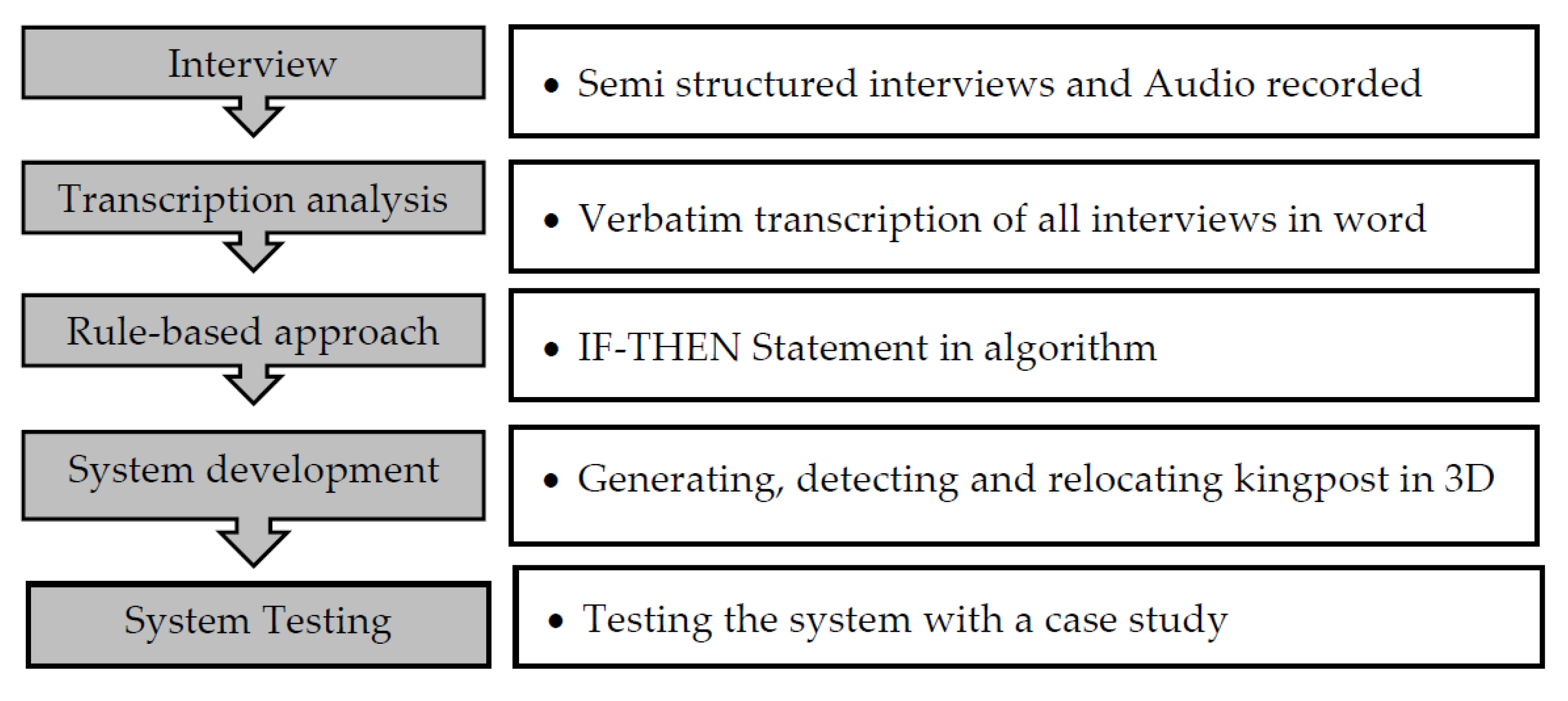
4. Research Methodology
System development uses the concept of integrating expertise and BIM technologies to detect and relocate clash problems between the kingposts and underground structures. The research methodology consists of five main steps. First, the knowledge of engineers was collected with some experts by the interview. Moreover, these experts were senior engineers of subcontractor companies in Thailand and had around 15 years of working experience in deep excavation. Next, after interviewing with experts, the information of the kingpost arrangement, which was analyzed by transcription analysis, was divided into three main parts, including (1) structural kingpost generation, (2) clash detection of kingpost, and (3) kingpost relocation. Brief information about each part was described in the next section. Then, this information was developed into the modules by using a rule-based approach. Last, a system was developed and tested using the rule-based approach and BIM technology. In the developed system, it was developed into three modules, including (1) module of structural kingpost generation, (2) module of kingpost clash detection, and (3) module of kingpost relocation. Then, BIM technology, which used some available computer software, including Autodesk Revit and Dynamo software, was applied with the three modules for generating, detecting, and relocating the structural kingpost. In the second stage, after the system was completely developed, a case study of underground structures from building construction was used in the system testing.
Figure 5 shows an overall process of research methodology.
4.1. Case Study
In practice, the main contractor is required to calculate the cost estimation for bid submission. The depth excavation is required the specialist sub-contractor to involve during the bidding process to support the cost estimates of the soil protection system. At this stage, the specialist subcontractor tries to develop a construction drawing of the bracing system. The construction drawing should be more realistic because the cost of temporary work is high. If the bidding cost of the strutting system is underestimated, it may affect cost overrun during the construction phase, while if the bidding cost of the strutting system is overestimated, it may affect the loss of bid competitiveness.
Due to the uncertainty of building requirements and limitation of bid preparation time, the construction drawing is needed to develop from preliminary design rather than detail design. Thus, the purpose of preliminary design is to develop an initial construction drawing and estimate the approximated cost for supporting the bidding price of the main contractor. The strutting system is proposed by previous research work. This research article focused on the issues related to kingposts, which have several conditions related to constructability and bidding cost variance.
During the primary design stage, the structural kingpost was developed by two main tasks, including the design and arrangement of the structural kingpost. However, this study did not relate to the detailed design of the structural kingpost, and it is focused on the preliminary design. The cost engineer is only focused on the arrangement of the structural kingpost, which may conflict with underground structures. If the kingpost can be arranged to avoid the underground structures, we can pull back and reuse the kingpost. However, the kingpost cannot be arranged to avoid other underground structures and may need to be embedded within the underground structures, which may cause the variance of bidding price. Therefore, the arrangement of kingpost is necessary to take the consideration during preliminary cost estimation.
4.2. Information Support of the Kingpost Arrangement
4.2.1. Information of Structural Kingpost Generation
In this state, the engineers of subcontractors usually did not have much time to consider many influencing factors for arranging the structural kingpost. It is essential to check the clash between kingposts and underground structures, as shown in
Figure 3. Thus, it could support the cost estimation for the bidding work faster. In the kingpost arrangement, it was generated after the structural strut was arranged already. The arrangement of the structural strut was studied in another paper [
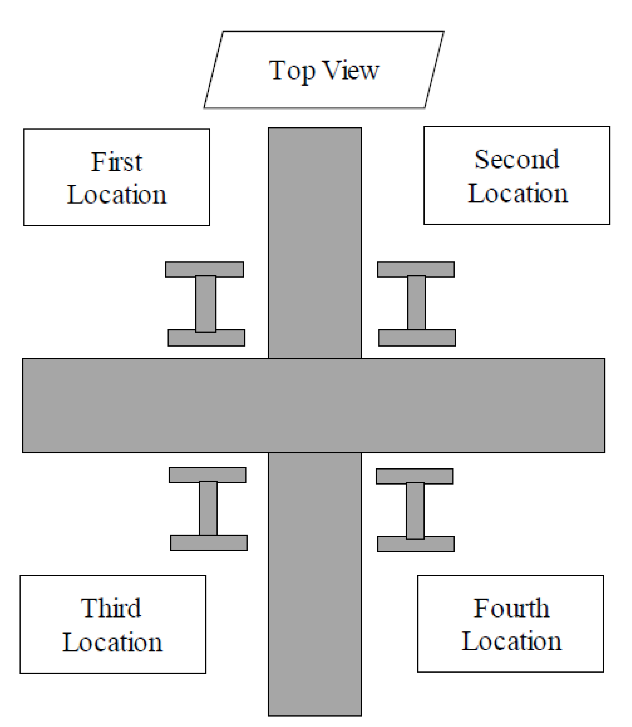
24]. Moreover, the space between kingpost and kingpost is not considered because the kingpost space followed the strut space that has already been checked in the strut arrangement stage. The kingpost location was placed at any angle of the intersection between strut and strut. There are four possible locations around the angle between strut and strut intersection.
Figure 6 shows the four possible locations of the kingpost on the top view.
4.2.2. Characteristics of Clash Detection between Kingpost and Underground Structures
The clash problem refers to the intersection between selected elements. In this study, the clash is checked between kingpost and underground structures. the structural kingpost detection is undertaken kingpost and underground structures, including pile, footing, column, girder, and wall. In some cases, if the kingpost only clashes with the footing and is not able to relocate to another place. This kingpost is cut and kept inside the footing as the embedded kingpost.
Figure 7 shows the IF-THEN condition statement of clash detection between kingpost and underground structures.
4.2.3. Characteristics of Kingpost Relocation
After identifying all clash problems from the detection process, the results generated the detected kingposts and other elements of underground structures, such as beams, walls, columns, piles, and footings. These problems were solved by relocating the kingpost to another angle of the intersection between strut and strut. There were four conditions of the kingpost location at the angle of strut and strut intersection that needed to consider for the relocation work.
Table 3 shows the four conditions of the kingpost location at the angle of the strut and strut intersection. Each condition had three relocation options in the original place. Moreover, each option had the module for moving the kingpost to another angle of the strut and strut intersection. In the relocation process, there were two steps in this development process. First, the relocation began by selecting a detected kingpost at the angle of the strut and the strut intersection in the 3D model. Next, the user should understand and select one of the options in the conditions that he or she wanted to relocate the kingpost. Moreover, after moving the kingpost location, the analysis is still re-checked for identifying the clash problems. This analysis attempted to ensure the new location of the kingpost has no clash problems. After the information support was collected from the interview, it was used to develop into the module of kingpost relocation.
4.2.4. Types of Kingpost
The structural kingpost was used to serve two main functions. First, the kingpost was used to reduce the strut span. Regarding the historical data of 25 building construction projects, the allowable span of the strut was determined around 6.5 m.
Figure 8 shows an allowable spacing number (L), and
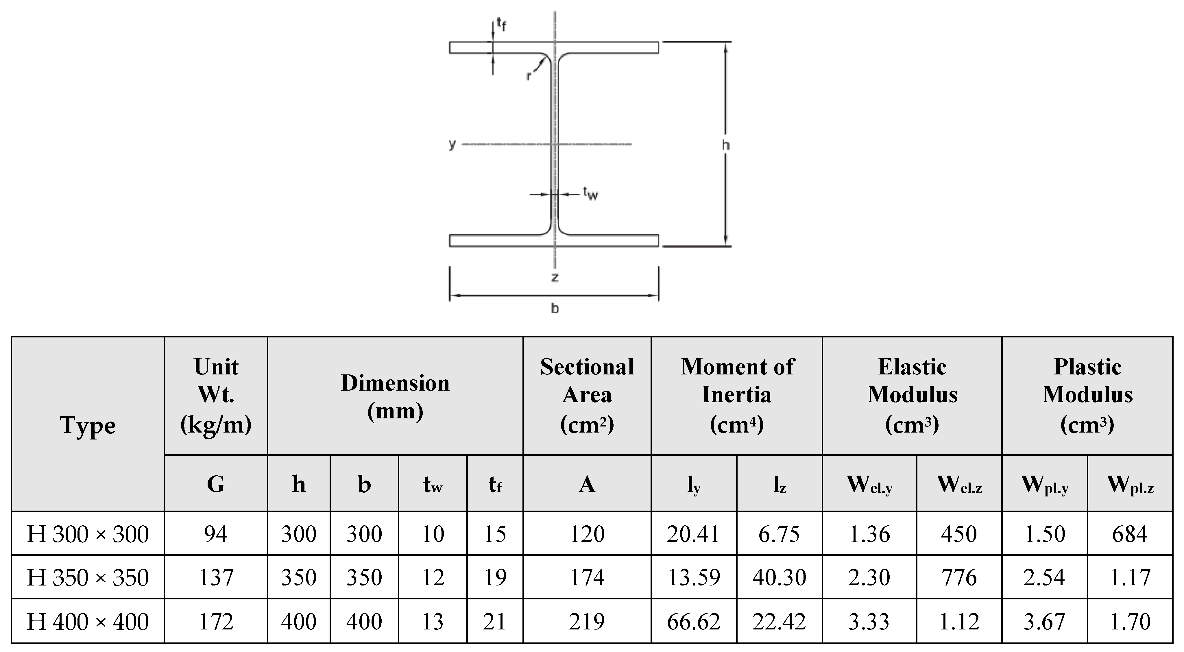
Table 4 shows allowable spacing numbers from 25 building construction projects in the deep excavation. Then, the strut span should be smaller than the allowable span of 6.5 m. If the strut span was bigger than the allowable span number, the strut could fail from its bracing work. Thus, the kingpost was used when the strut was longer than 6.5 m. Second, the kingpost was applied to support the structural strut and avoided the clash problems between the kingposts and underground structures. This study only focused on the identification and solution of the clash problems. Moreover, in the current market, three sizes of kingpost are commonly used, including HR400 mm, HR350 mm, and HR300 mm. This developed system allowed the user to select any size among these three types of kingposts.
Figure 9 shows the types of kingposts in Thailand.
4.3. System Development
After collecting the information support of the kingpost arrangement, this information needed to develop into the module of the system. There were three main stages of developed system. First, the module was initially developed for generating the initial structural kingpost in the 3D model. Next, the clash detection module was developed to identify the clash problems between the kingposts and underground structures. Third, the relocation module of the kingpost location was developed to relocate the kingpost to a suitable place. After solving the clash problems, a better structural kingpost could finally be obtained and generated into the 3D model.
Figure 10 shows three main stages of the developed system. Each stage had a module that are explained in the following section.
4.3.1. Module for Generating the Initial Structural Kingpost in the 3D Model
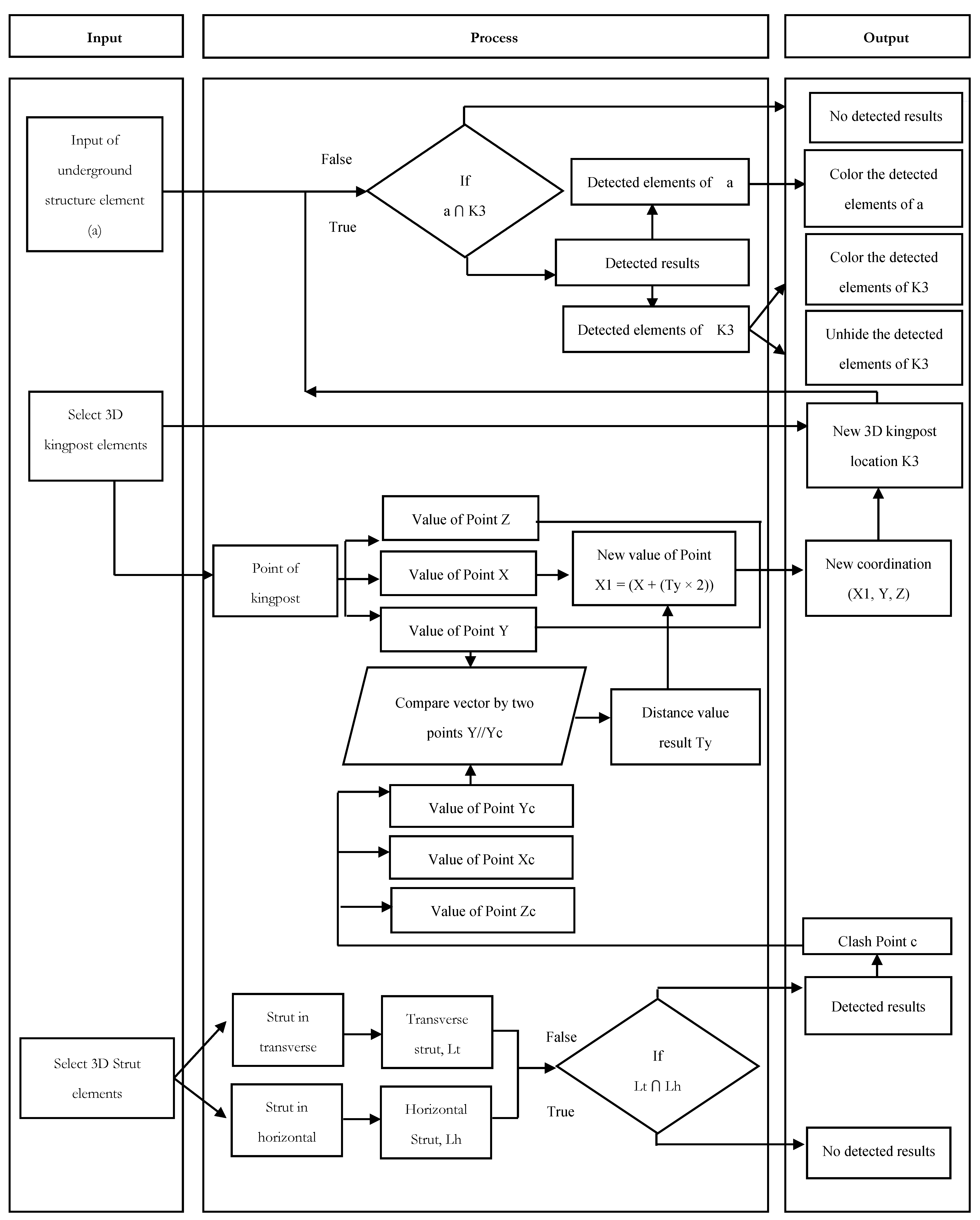
In the first stage, the initial structural kingpost was generated into the 3D model. The purpose of this module was to determine the kingpost position at any angle of intersection between strut and strut. There were many stages in the module of the structural kingpost generation. First, the user selected all 3D strut models and applied the rule-based approach with the intersection point between horizontal and transverse struts. Then each intersection point was added by (1) strut width with a value of Point X and (2) strut length with a value of Point Y. A new location of intersection point was obtained and generated into the 3D model by using one of the three kingpost family types.
Figure 11 shows a module of the structural kingpost generation.
4.3.2. Module for Detecting the Clash Problems
When the structural kingpost was obtained into the 3D model, this structure needed to check for detecting the clash problems between kingposts and other elements of underground structures. The development of the clash detection module was only focused on (1) kingposts and columns, (2) kingposts and walls, (3) kingposts and beams, and (4) kingposts and foundations that had piles and footings. In the clash detection module, the input of the rule-based approach was applied between the kingpost components and the other elements of underground structures such as beams, walls, columns, piles, and footings. After the detection process, the detected kingposts and elements of underground structures were found and shown in different colours. For example, the detected kingposts were shown in green colour, whereas the detected elements of underground structures were shown in orange colour.
Figure 12 shows a module of clash detection between kingposts and underground structures.
4.3.3. Modules for Kingpost Relocation
After the process of clash detection, the finding showed the detected kingposts and other elements of underground structures, including beams, walls, columns, piles, and footings. These clash problems were visualized in the 3D model. To solve the clash problems, the kingpost was required to relocate to another angle of intersection between strut and strut. There were four conditions of the strut intersection. Each condition had three main options that the kingpost, which was applied with the rule-based approach, could move to another angle of intersection between strut and strut. For example, when the original location of the kingpost was at the top left-hand side or first location, the kingpost was able to move to the other three locations of strut and strut intersection such as the second, third or fourth location. Each location had the module, as shown in
Figure 13. Moreover, after relocating the kingpost, it was also re-checked with the clash problems.
Figure 14,
Figure 15 and
Figure 16 show the modules of kingpost relocation to the second, third or fourth location.
4.4. Software for Developing System
To develop a system of kingpost arrangement, it is required to combine the module development with the current available BIM software. In this study, the modules of the kingpost arrangement were explained in the above section. Moreover, the BIM software, which used to serve in this developed system, consisted of Autodesk Revit and Dynamo Software.
Table 5 shows a brief description of each software in this study. As a result, this system was developed in three modules, including structural kingpost generation, clash detection of kingpost, and relocation of kingpost. The detailed information on the developed system with the BIM software was explained in another paper elsewhere.
5. A System Testing with a Case Study
5.1. Description of the Project
A project of basement construction in Bangkok, Thailand, was selected as a case study for validating the system. In this project, two office buildings had seven floors, and the height was 22.9 m. Furthermore, the total area of the three-floor basement was 4911.2 m
2. This basement was used to serve as a car parking lot. The width of the deep excavation was 31.5 m, the length was 77.7 m, and the depth was 14.6 m. Last, a 3D model of the underground structure was developed by using Autodesk Revit Software.
Figure 17 shows the 3D model of the basement.
5.2. Results of a System Testing
After each module of the system was completely developed and tested with a case study, the results could dramatically change the process of kingpost arrangement. First, the module of kingpost generation required a few steps for generating the structural kingpost in a 3D model. Moreover, it spent less time and required less user interaction in the kingpost generation process. Next, the module for detecting the clash of kingpost can present a clear picture of all underground structure elements that clashed with the kingpost in a 3D model at the same time. This also required the user to process the clash detection in a few steps. Last, the kingpost relocation module allowed the user to change the location of the kingpost easier and did not require much experience or skill for some engineers to find a suitable place to solve the clash between kingposts and underground structures. In short, these three modules of the kingpost arrangement provided the user less interaction with the system and less time to know the result of each module. Each module test was shown in the next section.
5.2.1. Step 1: Initial Structural Kingpost Generation in the 3D Model
- i.
Input Data Process of Structural Kingpost Generation
The structural kingpost generation aimed to determine the quantity and position of kingpost at any angle of intersection between strut and strut and generate in the 3D model. The input information was begun by choosing the structural strut in the 3D model. Then, the user should select one of three kingpost types.
Table 6 shows input information and the interface of the kingpost generation.
- ii.
The Result of Structural Kingpost Generation
After the input information was obtained from the structural strut selection in the 3D model, the dynamo ran the calculation process for determining the kingpost numbers and generated the structural kingpost in the 3D model. As a result, 48 kingposts were determined from the intersection between strut and strut and shown in
Table 7. Moreover, these kingposts were generated in the 3D model and shown in
Figure 18.
5.2.2. Step 2: Clash Detection of Structural Kingpost
- i.
Input Data Process of Clash Detection
After obtaining the initial structural kingpost, it was applied for detecting the clash problems between kingposts and other underground structures. In the input requirement, the user is required to select between kingposts and underground structures. There were five cases of clash detection. These cases were included (1) kingposts and walls, (2) kingposts and beams, (3) kingposts and footings, (4) kingposts and piles, and (5) kingposts and columns. All clash occurrences were checked at the same time.
Table 8 shows the input information and interface.
- ii.
The Result of Clash Problems
The underground structures, which included piles, footings, columns, walls, and beams, were chosen to detect the clash occurrences with the kingposts. Then, the clash detection found between kingposts and underground structures was obtained in a 3D environment.
Figure 19 shows the finding of kingpost clash detection.
5.2.3. Step 3: Relocation of Kingpost
- i.
Input Data Process of Kingpost Relocation
In the kingpost relocation, the clash was solved by modifying the kingpost to another angle of intersection between strut and strut. In the input information, there were three main tasks for the user. First, the user clicked the select elements button and went to select the kingpost and strut components in the 3D model. The information about the selected kingpost and strut could primarily explain the original location of the kingpost. Then, the user should select one of the options to tell the kingpost position. Last, the user could choose one option to move from the original location of the kingpost to one of three relocation locations.
Table 9 shows the input requirement and interface of a kingpost relocation.
- ii.
The Result of Kingpost Relocation
When the input was provided in the kingpost relocation module, the Autodesk Dynamo Software processed the data for relocating the kingpost to another angle of intersection between strut and strut. After relocating the kingpost, the clash detection process ran to check the clash problems between the kingposts and underground structures at the same time. If the relocation results still detected clash problems, the user had to run this relocation process again. Thus, the kingpost relocation could overcome the clash problem of kingposts.
Table 10 shows the results of the kingpost relocation.
6. Discussion of System Development
To comprehensively understand the system, it was brought to another interview with the same experts. The finding results of the developed system were significantly determined and explained in the following section.
First, this study has improved the visualization environment of the kingpost arrangement. Two-dimensional drawings were usually used by the engineer in traditional practice. However, it is limited to display the clashes between kingposts and underground structures. Then, the development of the system aimed to visualize the clashes in the 3D environment. Based on the arrangement information of kingpost, the clash detection module was developed to identify the clash problems. Then, this module integrated with the BIM technology for visualizing all clash problems on each kingpost at the same time. Finally, the 3D clash results were successfully visualized on each kingpost. Thus, the module of clash detection provided the advantage of visualization in the 3D environment.
Second, each module of the system could help the user with the kingpost arrangement. The user just created the basement and structural strut in the 3D model. Then, the user can apply this system for generating the structural kingpost, detecting the clash problems between kingposts and underground structural elements, and arranging the suitable location of the kingpost. Moreover, this system required little input information to automatically run its function. At last, a better structure of kingpost was finally generated without the clashes between kingposts and underground structures. Therefore, the user did not need to have a high knowledge or skill related to the kingpost arrangement. The preliminary design can help contractors to estimate the cost of the temporary item for deep excavation work.
Although the automated system for supporting the kingpost arrangement work is developed successfully, it still has a limitation that encourages many scholars who are interested in this problem to study more in the future. First, the only fixing number of kingpost sizes used in this research included HR400 mm, HR350 mm, and HR300 mm. Although different ground layers could have different lateral forces in the deep excavation, different numbers of kingpost sizes could be selected for supporting the strutting system. Thus, the development of the structural kingpost generation module did not consider the design work. Moreover, the engineers could separately use each module of the kingpost arrangement. They could skip the generation module of structural kingpost and directly use the modules of clash detection and kingpost relocation. Second, since this system has developed with the practical knowledge of kingpost arrangement and BIM technology, it was expected that some junior engineers would be allowed to properly arrange the structural kingpost. To prove this idea, this study also aims to bring the developed system for testing with some junior engineers. This testing will allow these engineers to use the system and interview them to learn about the benefits and limitations of the system. By knowing about the perception of some junior engineers, we will be able to improve the developed system too. However, due to the time limitation in this study, this study does not have enough time to prove the testing result for junior engineers.
7. Conclusions
Due to traditional practice and some available construction programs, the kingpost arrangement was still unable to visualize concurrent clashes between each kingpost and underground structures at the same time. To solve this problem, this research study used visual programming interaction with Building Information Modelling. The developed system uses the concept of integrating expertise and BIM technologies to detect and resolve clash problems between the kingposts and underground structures. In the methodology, the information supporting the kingpost arrangement was initially collected from experts’ interviews of subcontractor companies in Thailand. This information has characteristics of (1) structural kingpost generation, (2) clash detection of kingpost, and (3) kingpost relocation. Then, the provided information was used to develop the modules of the system. Last, the system was developed by BIM technology. In this developed system, there were three main functions: (1) structural kingpost generation, (2) clash detection of kingpost, and (3) the relocation of kingpost location. In short, the development of this system could support the kingpost arrangement and improve the visualization of clash problems in the 3D model.
This study has only focused on the arrangement of the structural kingpost. Future research studies are encouraged to focus on other components of the strutting system, such as the platform. The platform structure should be analyzed for effectively supporting the road access with heavy equipment, such as excavators and trucks, in the deep excavation process. Therefore, to avoid other constructible problems, further studies should focus on adapting the advanced construction technology with the platform structure.
Author Contributions
Conceptualization, V.P., P.N. and T.T.; methodology, V.P., P.N. and T.T.; software, V.P., P.N. and T.T.; validation, V.P., P.N. and T.T.; formal analysis, V.P. and P.N.; investigation, V.P. and P.N.; resources, V.P. and T.T.; data curation, P.N.; writing—original draft preparation, V.P. and P.N.; writing—review and editing, V.P. and P.N.; visualization, P.N.; supervision, V.P. and T.T.; project administration, V.P. and T.T.; funding acquisition, V.P. and P.N. All authors have read and agreed to the published version of the manuscript.
Funding
This research was funded by the 90th Anniversary Fund of Chulalongkorn University (Ratchadaphiseksomphot Endowment Fund) and the ASEAN scholarship program.
Data Availability Statement
The data are available on request from the corresponding author.
Acknowledgments
Authors would like to thank all engineers who provide in-depth information and the valuable comments about the strut system preliminary design, especially Nirundorn Nata, Technical Manager from Altemtech Co., Ltd. (Bangkok, Thailand).
Conflicts of Interest
The authors declare no conflict of interest.
References
- Fantaziu, C.; Chirila, R. Study Achievement of Deep Excavations from the Point of View of Their Effects on Surrounding Existing Buildings. J. Sustain. Arch. Civ. Eng. 2014, 7, 74–80. [Google Scholar] [CrossRef][Green Version]
- Chao, S.H.; Karki, N.B.; Sahoo, D.R. Seismic Behavior of Steel Buildings with Hybrid Braced Frames. J. Stru. Eng. 2013, 139, 1019–1032. [Google Scholar] [CrossRef]
- Kaveh, A.; Abadi, A.S.M. Harmony Search Based Algorithms for the Optimum Cost Design of Reinforced Concrete Cantilever Retaining Walls. Inter. J. Civ. Eng. 2011, 9, 1–8. [Google Scholar]
- Askew, I. Deep Excavations-Industry Challenges; Geotechnical Division, APEC Seminar on The State-of-the-Practice of Deep Excavation Works; The Hong Kong Institution of Engineers: Hong Kong, China, 21 May 2011; pp. 105–110. [Google Scholar]
- Toh, G.S.H. Constructability and Safety Perspectives in Design of a Deep Basement Excavation in the Urban District of Tsim Sha Tsui. In Proceedings of the 30th Annual Seminar Geotechnical Division, Hong Kong, China, 6 May 2010; pp. 133–140. [Google Scholar]
- Muthomi, M.A. A Study of Deep Excavations and Excavation Support Systems in Soft Soils. 2016, pp. 1–10. Available online: https://www.semanticscholar.org/paper/A-Study-of-Deep-Excavations-and-Excavation-Support-Muthomi-adrianmunyua/80085b1df02680fe8539ec8008fc13802be31418 (accessed on 20 August 2020).
- Liew, S.S.; Loh, Y.E. Two Case Studies of Collapsed Temporary Excavation Using Contiguous Bored Pile Wall. In Proceedings of the CIEHKIEIEM Tripartied Seminar (Deep Excavation), Hong Kong, China, 21 May 2011; pp. 39–61. [Google Scholar]
- Lin, H.M.; Hadiprino, F.C. Problems in Deep Foundation Construction in Taiwan. J. Perform. Constr. Facil. 1990, 4, 259–270. [Google Scholar] [CrossRef]
- Aye, Z.Z.; Boonyarak, T.; Thasnanipan, N.; Prongmanee, N. Diaphragm Wall Support Deep-Excavations for Underground Space in Bangkok Subsoil. In Proceedings of the International Conference & Exhibition on Tunnelling & Underground Space (ICETUS2015), Kuala Lumpur, Malaysia, 3–5 March 2015; Available online: https://www.seafco.co.th/storage/download /innovation/2015/diaphragm-wall-support-deep-excavations.pdf (accessed on 20 August 2020).
- Marr, W.A.; Hawkes, M. Displacement-Based Design for Deep Excavations. In Proceedings of the Earth Retention Conference, Bellevue, WA, USA, 1–4 August 2010; pp. 1–18. [Google Scholar] [CrossRef]
- Jadidoleslami, S.; Saghatforoush, E.; Zare Ravasan, A. Constructability Obstacles: An Exploratory Factor Analysis Approach. Int. J. Constr. Manag. 2018, 21, 312–325. [Google Scholar] [CrossRef]
- Ding, L.Y.; Zhong, B.T.; Wu, S.; Luo, H.B. Construction Risk Knowledge Management in BIM Using Ontology and Semantic Web Technology. Saf. Sci. 2016, 87, 202–213. [Google Scholar] [CrossRef]
- Macnab, A. Earth Retention Systems Handbook; McGrawHill: New York, NY, USA, 2002. [Google Scholar]
- Lu, S.-R.; Wu, I.C.; Hsiung, B.-C.B. Applying BIM in Environmental Impact Assessment for Urban Deep Excavation Projects. In Proceedings of the 29th International Symposium on Automation and Robotics in Construction, Eindhoven, The Netherlands, 26–29 June 2012; pp. 1–6. [Google Scholar]
- Luo, H.; Gong, P. A BIM-based Code Compliance Checking Process of Deep Foundation Construction Plans. J. Intell. Robot. Syst. 2015, 79, 549–576. [Google Scholar] [CrossRef]
- Li, M.; Yu, H.; Liu, P. An Automated Safety Risk Recognition Mechanism for Underground Construction at the Pre-Construction Stage Based on BIM. Autom. Constr. 2018, 91, 284–292. [Google Scholar] [CrossRef]
- Gondar, J.; Fartaria, C.; Pinto, A. Case Study: BIM and Geotechnical Project in Urban Area-Infinity Tower. In Proceedings of the China-Europe Conference on Geotechnical Engineering, Vienna, Austria, 3 August 2018; pp. 923–926. [Google Scholar]
- Singh, M.M.; Sawhney, A.; Borrmann, A. Integrating Rules of Modular Coordination to Improve Model Authoring In BIM. J. Con. Manag. 2017, 19, 15–31. [Google Scholar] [CrossRef]
- Tian, Y.; Yue, H. Application Research of BIM Technology in Computer Aided Design of Building Foundation. Chem. Eng. Trans. 2016, 51, 427–432. [Google Scholar] [CrossRef]
- Choi, M.; Lee, G.; Kim, H. A Framework for Evaluating Deep Excavation Alternatives in Building Construction. In Proceedings of the International Conference on Computing in Civil and Building Engineering (ICCCBE), Beijing, China, 16–18 October 2008; pp. 1–6. [Google Scholar]
- Wu, I.C.; Lu, S.R.; Hsiung, B.C. A BIM-Based Monitoring System for Urban Deep Excavation Projects. Visualization Eng. 2015, 3, 1–11. [Google Scholar] [CrossRef]
- Lin, J.; Zhang, J.; Wen, Q.; Wang, F. Leveraging BIM in Settlement Monitoring and Impact Management for Subway Excavation. In Proceedings of the 32nd CIB W78 International Conference on Information Technology for Construction, Eindhoven, The Netherlands, 27–29 October 2015; pp. 469–477. [Google Scholar]
- Szwarkowski, D.; Pilecka, E. BIM Technology in Geotechnical Engineering in Terms of Impact High Building “Mogilska Tower” in Cracow of Existing Building Development. Tech. Sci. 2017, 20, 297–309. [Google Scholar] [CrossRef]
- Nov, P.; Peansupap, V.; Tongthong, T. Developing an Automated System for Checking the Strut Arrangement in Deep Excavation. Eng. J. 2021, 25, 99–124. [Google Scholar] [CrossRef]
- Tanaka, C.; Hong, C.I.W. Application of BIM in Geotechnics–Case Study on a Deep Excavation Project. In Proceedings of the 6th International Young Geotechnical Engineers’ Conference, Seoul National University, Seoul, Korea, 16–17 September 2017; pp. 1–2. [Google Scholar]
Figure 1.
Components of the strutting system.
Figure 1.
Components of the strutting system.
Figure 3.
Examples of clash avoidance between kingpost and underground structure.
Figure 3.
Examples of clash avoidance between kingpost and underground structure.
Figure 4.
A comparison of kingpost relocation by using the available construction program and the proposed idea.
Figure 4.
A comparison of kingpost relocation by using the available construction program and the proposed idea.
Figure 5.
The research process methodology.
Figure 5.
The research process methodology.
Figure 6.
A picture of the kingpost location.
Figure 6.
A picture of the kingpost location.
Figure 7.
The IF-THEN condition statement of clash detection between kingpost and underground structures.
Figure 7.
The IF-THEN condition statement of clash detection between kingpost and underground structures.
Figure 8.
An allowable spacing number (L).
Figure 8.
An allowable spacing number (L).
Figure 9.
Types of kingposts in Thailand.
Figure 9.
Types of kingposts in Thailand.
Figure 10.
Three main stages of the developed system.
Figure 10.
Three main stages of the developed system.
Figure 11.
A module of structural kingpost generation.
Figure 11.
A module of structural kingpost generation.
Figure 12.
A module of clash detection between kingposts and underground structures.
Figure 12.
A module of clash detection between kingposts and underground structures.
Figure 13.
Three options of kingpost relocation.
Figure 13.
Three options of kingpost relocation.
Figure 14.
A module of kingpost relocation to the second location.
Figure 14.
A module of kingpost relocation to the second location.
Figure 15.
A module of kingpost relocation to the third location.
Figure 15.
A module of kingpost relocation to the third location.
Figure 16.
A module of kingpost relocation to the fourth location.
Figure 16.
A module of kingpost relocation to the fourth location.
Figure 17.
Three-floor basement of office building construction in the 3D model.
Figure 17.
Three-floor basement of office building construction in the 3D model.
Figure 18.
An initial structural kingpost generation in plan and 3D views.
Figure 18.
An initial structural kingpost generation in plan and 3D views.
Figure 19.
Clash detection of kingposts in a 3D environment.
Figure 19.
Clash detection of kingposts in a 3D environment.
Table 1.
An example of a comparison between available construction program and proposed idea.
Table 2.
Studies between the deep excavation and BIM.
Table 2.
Studies between the deep excavation and BIM.
| References | Research Description |
|---|
| [14] | Focused on developing a 3D building and excavation model in a real-world case study. As a result, the monitoring data of the system could measure the settlement of soil. Moreover, it could analyze the impact of the environment on the ground surface. |
| [21] | Integrated a BIM technology for identifying the risk in monitoring work of the deep excavation. Moreover, the system also could visualize the instrument’s location in the 3D environment. Last, the developed system also provided the data required for assessing the ground settlement. |
| [22] | Established settlement monitoring and impact management by using a BIM-based approach. This research could identify the risks by comparing warning levels and monitoring data. Therefore, this system could control the impact of ground settlement. |
| [23] | Used BIM to model a high building, “Mogilska Tower”, in Cracow. This study checked the settlement and evaluated the neighboring building’s impact. |
| [24] | Applied with BIM for checking the clash with the structural strut. However, it focused on a different element of the strutting system, which served a different function for supporting the retaining wall. |
Table 3.
Four conditions of kingpost location at the angle of strut intersection.
Table 4.
Allowable spacing numbers (L) from 25 deep excavation projects.
Table 4.
Allowable spacing numbers (L) from 25 deep excavation projects.
| DESIGN STRUT | Strut Type | F max. - Worst Case, F | L | L1 | Section Area | Radius of Gyration | Effective Length | Allowable Stress, Fa | Actual Stress, fa | fa < Fa |
|---|
| | | (t/m) | (m) | (m) | (cm2) | (cm) | (m) | (ksc) | (ksc) | |
|---|
| Project 1 | 300 × 300 | 14 | 6.5 | 6.5 | 119.8 | 7.5 | 86.6 | 1000.9 | 875.6 | Ok |
| 400 × 400 | 31.1 | 6.5 | 6.5 | 218.7 | 10.1 | 64.4 | 1150.7 | 1040.3 | Ok |
| 350 × 350 | 24.6 | 6.5 | 6.5 | 173.9 | 8.8 | 73.5 | 1091.5 | 1035.5 | Ok |
| 300 × 300 | 9.3 | 6.5 | 6.5 | 119.8 | 7.5 | 86.6 | 1000.9 | 620.6 | Ok |
| 350 × 350 | 25.8 | 6.5 | 6.5 | 173.9 | 8.8 | 73.5 | 1091.5 | 1080.4 | Ok |
| 350 × 350 | 23.5 | 6.5 | 6.5 | 173.9 | 8.8 | 73.5 | 1091.5 | 994.4 | Ok |
| Project 2 | 300 × 300 | 4.7 | 6.5 | 6.5 | 119.8 | 7.5 | 86.6 | 1000.9 | 370.1 | Ok |
| 350 × 350 | 18 | 6.5 | 6.5 | 173.9 | 8.8 | 73.5 | 1091.5 | 787.3 | Ok |
| 300 × 300 | 12.1 | 3 | 5.2 | 119.8 | 7.5 | 69.2 | 1119.7 | 420 | Ok |
| Project 3 | 300 × 300 | 14.6 | 6 | 6 | 119.8 | 7.5 | 79.9 | 1048.2 | 847.7 | Ok |
| 350 × 350 | 25.1 | 6 | 6 | 173.9 | 8.8 | 67.9 | 1128.5 | 981.7 | Ok |
| 350 × 350 | 29.7 | 6 | 6 | 173.9 | 8.8 | 67.9 | 1128.5 | 1140 | Ok |
| Project 4 | 350 × 350 | 7.3 | 6.5 | 6.5 | 173.9 | 8.8 | 73.5 | 1091.5 | 390 | Ok |
| 350 × 350 | 15.7 | 6.5 | 6.5 | 173.9 | 8.8 | 73.5 | 1091.5 | 702.8 | Ok |
| Project 5 | 300 × 300 | 9.1 | 8.5 | 4.2 | 119.8 | 7.5 | 56.2 | 1200 | 763.6 | Ok |
| 300 × 300 | 11 | 7.6 | 4.8 | 119.8 | 7.5 | 63.9 | 1153.4 | 807.6 | Ok |
| 300 × 300 | 14.2 | 7.6 | 4.8 | 119.8 | 7.5 | 63.9 | 1153.4 | 1013.4 | Ok |
| Project 6 | 300 × 300 | 12.2 | 6 | 6 | 119.8 | 7.5 | 79.9 | 1048.2 | 725.5 | Ok |
| 400 × 400 | 34.5 | 6 | 6 | 218.7 | 10.1 | 59.4 | 1181 | 1061.7 | Ok |
| 350 × 350 | 27.9 | 6 | 6 | 173.9 | 8.8 | 67.9 | 1128.5 | 1079.3 | Ok |
| Project 7 | 300 × 300 | 10.5 | 6 | 6 | 119.8 | 7.5 | 79.9 | 1048.2 | 640.4 | Ok |
| 350 × 350 | 20.3 | 6 | 6 | 173.9 | 8.8 | 67.9 | 1128.5 | 814.7 | Ok |
| Project 8 | 350 × 350 | 19.2 | 6.5 | 6.5 | 173.9 | 8.8 | 73.5 | 1091.5 | 831.8 | Ok |
| 350 × 350 | 29.5 | 6.5 | 6.5 | 173.9 | 8.8 | 73.5 | 1091.5 | 1218.3 | Ok |
| Project 9 | 300 × 300 | 11.4 | 2.5 | 6.6 | 119.8 | 7.5 | 87.9 | 991.1 | 353.1 | Ok |
| Project 10 | 300 × 300 | 3.9 | 6.7 | 6 | 119.8 | 7.5 | 79.9 | 1048.2 | 335.5 | Ok |
| 300 × 300 | 12.1 | 6.7 | 6 | 119.8 | 7.5 | 79.9 | 1048.2 | 794.1 | Ok |
| Project 11 | 300 × 300 | 12.6 | 3.4 | 12 | 119.8 | 7.5 | 157.1 | 437.6 | 351 | Ok |
| 350 × 350 | 17 | 3.4 | 12 | 173.9 | 8.8 | 133.5 | 606.3 | 326.9 | Ok |
| Project 12 | 300 × 300 | 12.6 | 6 | 6.5 | 119.8 | 7.5 | 86.6 | 1000.9 | 747.6 | Ok |
| Project 13 | 300 × 300 | 12.6 | 6.5 | 6.5 | 119.8 | 7.5 | 86.6 | 1000.9 | 799.6 | Ok |
| 300 × 300 | 15.3 | 6.5 | 6.5 | 119.8 | 7.5 | 86.6 | 1000.9 | 946.1 | Ok |
| Project 14 | 350 × 350 | 15 | 6.5 | 6.5 | 173.9 | 8.8 | 73.5 | 1091.5 | 677.8 | Ok |
| 400 × 400 | 30.5 | 6.5 | 6.5 | 218.7 | 10.1 | 64.4 | 1150.7 | 1021.3 | Ok |
| 350 × 350 | 20.6 | 6.5 | 6.5 | 173.9 | 8.8 | 73.5 | 1091.5 | 884.1 | Ok |
| Project 15 | 350 × 350 | 16.2 | 6.5 | 6.5 | 173.9 | 8.8 | 73.5 | 1091.5 | 720 | Ok |
| 350 × 350 | 42.4 | 6.5 | 6.5 | 173.9 | 8.8 | 73.5 | 1091.5 | 908 | Ok |
| 400 × 400 | 33.4 | 6.5 | 6.5 | 218.7 | 10.1 | 64.4 | 1150.7 | 1108.5 | Ok |
| 350 × 350 | 18.9 | 6.5 | 6.5 | 173.9 | 8.8 | 73.5 | 1091.5 | 823.6 | Ok |
| Project 16 | 300 × 300 | 10.4 | 6 | 6 | 119.8 | 7.5 | 79.9 | 1048.2 | 635.4 | Ok |
| 300 × 300 | 28.6 | 6 | 6 | 119.8 | 7.5 | 79.9 | 1225.3 | 1222.7 | Ok |
| 350 × 350 | 24.1 | 6 | 6 | 173.9 | 8.8 | 67.9 | 1128.5 | 948.9 | Ok |
| 350 × 350 | 18.6 | 6 | 6 | 173.9 | 8.8 | 67.9 | 1128.5 | 758.8 | Ok |
| Project 17 | 300 × 300 | 11.6 | 6.5 | 6.5 | 119.8 | 7.5 | 86.6 | 1000.9 | 744.3 | Ok |
| 350 × 350 | 25.5 | 6.5 | 6.5 | 173.9 | 8.8 | 73.5 | 1091.5 | 1069.9 | Ok |
| Project 18 | 350 × 350 | 22 | 6.5 | 7 | 173.9 | 8.8 | 79.2 | 1053.1 | 938.3 | Ok |
| 350 × 350 | 48 | 6.5 | 7 | 347.8 | 8.8 | 79.2 | 1053.1 | 1013.1 | Ok |
| 400 × 400 | 64 | 6.5 | 7 | 437.4 | 10.1 | 69.3 | 1119.3 | 1067.1 | Ok |
| 350 × 350 | 50 | 6.5 | 7 | 347.8 | 8.8 | 79.2 | 1053.1 | 1053.1 | Ok |
| Project 19 | 400 × 400 | 29 | 6.5 | 6.5 | 218.7 | 10.1 | 64.4 | 1150.7 | 977.9 | Ok |
| 400 × 400 | 25.5 | 6.5 | 6.5 | 218.7 | 10.1 | 64.4 | 1150.7 | 873.9 | Ok |
| Project 20 | 400 × 400 | 26.9 | 6.5 | 6.5 | 218.7 | 10.1 | 63.7 | 1154.6 | 914.3 | Ok |
| 400 × 400 | 57.4 | 6.5 | 6.5 | 437.4 | 10.1 | 63.7 | 1154.6 | 968.3 | Ok |
| 400 × 400 | 27.6 | 6.5 | 6.5 | 218.7 | 10.1 | 63.7 | 1154.6 | 937.2 | Ok |
| Project 21 | 400 × 400 | 35 | 6 | 6 | 218.7 | 10.1 | 59.4 | 1181 | 1076.2 | Ok |
| 400 × 400 | 61 | 6 | 6 | 437.4 | 10.1 | 59.4 | 1181 | 952.8 | Ok |
| 400 × 400 | 57 | 6 | 6 | 437.4 | 10.1 | 59.4 | 1181 | 897.9 | Ok |
| Project 22 | 350 × 350 | 18.7 | 5.5 | 5.5 | 173.9 | 8.8 | 62.2 | 1163.9 | 707.4 | Ok |
| 350 × 350 | 36.7 | 5.5 | 5.5 | 347.8 | 8.8 | 62.2 | 1163.9 | 696.4 | Ok |
| 350 × 350 | 45 | 5.5 | 5.5 | 347.8 | 8.8 | 62.2 | 1163.9 | 827.6 | Ok |
| Project 23 | 350 × 350 | 20.7 | 7 | 6.5 | 173.9 | 8.8 | 73.5 | 1091.5 | 949.2 | Ok |
| 400 × 400 | 23.4 | 8 | 6.5 | 218.7 | 10.1 | 64.4 | 1150.7 | 972 | Ok |
| Project 24 | 350 × 350 | 29 | 6.5 | 6.5 | 347.8 | 8.8 | 62.2 | 1163.9 | 658 | Ok |
| 350 × 350 | 39 | 6.5 | 6.5 | 347.8 | 8.8 | 62.2 | 1163.9 | 844.9 | Ok |
| 350 × 350 | 53 | 6.5 | 6.5 | 347.8 | 8.8 | 62.2 | 1163.9 | 1068.4 | Ok |
| 350 × 350 | 55 | 6.5 | 6.5 | 347.8 | 8.8 | 62.2 | 1163.9 | 1067.7 | Ok |
| 400 × 400 | 62 | 6.5 | 6.5 | 437.4 | 10.1 | 59.4 | 1181 | 1037.4 | Ok |
| Project 25 | 350 × 350 | 29 | 6.5 | 6.5 | 218.7 | 10.1 | 68.3 | 1125.6 | 977.6 | Ok |
| 400 × 400 | 40.8 | 6.5 | 6.5 | 347.8 | 8.8 | 62.2 | 1163.9 | 878 | Ok |
| 350 × 350 | 26.5 | 6.5 | 6.5 | 218.7 | 10.1 | 68.3 | 1125.6 | 903 | Ok |
Table 5.
A brief description of each software.
Table 5.
A brief description of each software.
| Software Icon | Description |
|---|
 | Name: Autodesk Revit Software Version: 2018
Objective: Revit software could empower design and construction works by following a 3D coordination model.
Function: The software consists of all functional disciplines including structure, architecture, and MEP. |
 | Name: Autodesk Dynamo Software
Version: 1. DynamoRevit2.1.0.5697_20180730
2. DynamoInstall2.0.2
Objective: This software is open-source visual programming that allows the user to create the design alternatives, and process the data automation.
Function: When uses with other applications, it can manipulate and interconnect complex systems such as CAD, Building Information Models, and simulation engines. |
Table 6.
The input and interface of the structural kingpost generation.
Table 6.
The input and interface of the structural kingpost generation.
| Input | Interface |
|---|
| Select all struts in the 3D model |  |
Table 7.
The result of structural kingpost generation.
Table 7.
The result of structural kingpost generation.
| Generation of Structural Kingpost | Finding Results |
|---|
| Kingpost Numbers | 4 × 12 = 48 |
Table 8.
The input and interface of clash detection.
Table 8.
The input and interface of clash detection.
| Input | Interface |
|---|
Select model elements -> Select 3D kingposts model
Select model elements -> Select other 3D underground structures including columns, walls, beams, piles, and footings |  |
Table 9.
The input and interface of kingpost relocation.
Table 9.
The input and interface of kingpost relocation.
| Input | Interface |
|---|
| Select a 3D kingpost model |  |
Table 10.
Results of the kingpost relocation.
| Publisher’s Note: MDPI stays neutral with regard to jurisdictional claims in published maps and institutional affiliations. |
© 2021 by the authors. Licensee MDPI, Basel, Switzerland. This article is an open access article distributed under the terms and conditions of the Creative Commons Attribution (CC BY) license (https://creativecommons.org/licenses/by/4.0/).


