Article

A Conceptual Design Approach for Archaeological Structures, a Challenging Issue between Innovation and Conservation: A Studied Case in Ancient Pompeii

by
Vincenzo Calvanese
and
Alessandra Zambrano
*
Ministry of Culture, Pompeii Archaeological Park, 80045 Pompeii, Italy
*
Author to whom correspondence should be addressed.
Buildings 2021, 11(4), 167; https://doi.org/10.3390/buildings11040167
Submission received: 16 February 2021 / Revised: 22 March 2021 / Accepted: 31 March 2021 / Published: 15 April 2021
(This article belongs to the Special Issue Advanced Methods for Structural Rehabilitation)

Abstract

:
The preservation of the authenticity of a building artifact in an archaeological area is a responsible practice. On the other hand, the need to save the building artifact from natural and anthropic degradation and ensuring the structural reliability as well as an efficient maintenance program are big challenges. These tasks usually involve the cooperation of several professionals and the responsible use of innovative techniques and materials. This paper focused on a specific design approach for the rehabilitation works of ancient constructions at archaeological sites. The proposed approach implies different steps that allow for design optimization at an increasing knowledge level of the existing structures. In the archaeological area, some crucial design aspects cannot be defined before the execution work phase, since some elements can only be revealed and identified during work execution. As a consequence, the final design has often been optimized after all the information has been acquired. A studied case at the archaeological site of Pompeii is herein presented to prove the efficiency of the proposed approach. This methodology reduces the uncertainty related due to the ancient material performance, to the level of damage and to the effectiveness of the rehabilitation work, unknown at the design stage.

1. Introduction

The design process in archeological sites is normally complex, as soon as several constraints influence the final results. Often, the need to protect decorative surfaces at archaeological sites yields to building new roofs, and, as a consequence, to an extensive strengthening of the masonry walls to support the roof load. Alternatively, the need for the protection of decorative surfaces yields to building provisional roof structures or permanent roofs having a proper structure and foundation that are often very invasive in the archaeological space [1,2,3,4,5,6]. In the design process, the decision making phase, in order to define the types of intervention, the materials and technologies are crucial for an optimum rehabilitation project. Some authors have dealt with these issues of the rehabilitation of archaeological structures, and in particular, the archaeological site of Pompeii [1,2,3,4,5,6]. The design decision is often animated by intensive discussions among scientists, architects, engineers, and archeologists that face the problems and propose design solutions according to their particular prospective. The optimum design should be found by considering and weighting all different aspects by using a cost–benefit analysis that is oriented to the preservation of the material fabric with a reduced invasiveness of the intervention works.
All rehabilitation measures aim toward a conservation oriented objective that excludes as far as possible the dismantling or replacement of material or structural elements. In a historic building, actual consolidation practice and experience, based on contemporary knowledge, has introduced a broad spectrum of materials and devices able to improve its performance when subjected to static and dynamic loads [7]. In this context, the use of steel is a very prominent construction material as far as its high characteristics of reversibility, which make steel very useful in the cultural heritage environment. On the other hand, most designers are often oriented toward the use of compatible and natural materials such as wood, stone, etc. [7,8,9]. For these reasons, during the design process, the decision of the type of intervention and material yields different solutions, and consequently, different safety levels against the identified actions.
In the following, a design rehabilitation approach is presented, which aims to consider the constraints coming from the material fabric, the conservation principle as well as the structural performance and safety. The constraints coming from conservation theory make it rather impossible to reach the performance levels defined by the seismic codes in new constructions for the required probability within a specific conventional life, as evidenced by several authors [10,11,12,13]. Strengthening the design of archaeological structures in order to meet the requirements of seismic codes often leads to invasive interventions that are not compatible with the principles of conservation.
In the literature, most authors have focused their attention on the testing and monitoring of the structural properties of buildings and monuments [14,15,16,17,18,19,20] in order to understand the rehabilitation needs of the structures. A few authors [21,22,23,24,25], interested in assessing the structural challenges at archaeological sites, have investigated the aspects related to the challenge of considering both the seismic requirements and conservation of the authenticity of the material fabric.
The proposed interactive design approach, based on extensive experimental testing results, allows the professionals to optimize the design, to efficiently localize the intervention, and to introduce new design solutions and materials while respecting the principles of restoration for cultural heritage and the constraints of seismic construction codes.
The design approach was herein applied to the archaeological area of Pompeii. The rest of this paper is organized as follows. Section 2 presents the conceptual design approach, and the differences in the methodology between the approach used in ordinary cultural heritage structures and the one in the archaeological context are discussed. Section 3 describes the application of the design approach in the rehabilitation works and the construction of new roofs in the Championnet area of Pompeii (Regio VIII, Insula 2, 1-2-3): Section 3.1 is dedicated to the experimental campaign; Section 3.2 presents the structural modeling and the design of the interventions based on the results of the analysis, and finally, Section 3.3 shows the structural performance results.

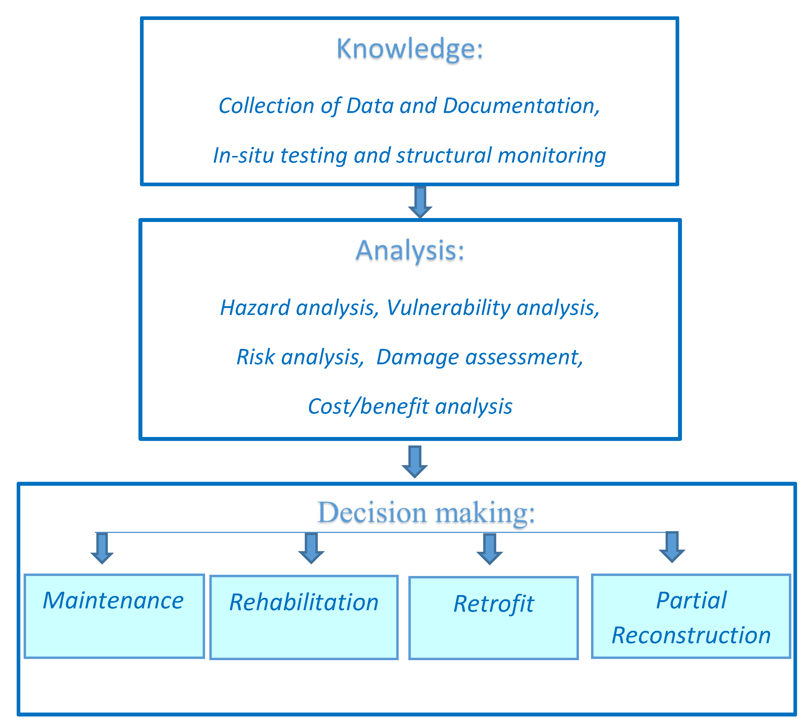
2. Conceptual Design Approach

Design Decision Making Analysis

The structural design of cultural heritage artifacts is conditioned by several constrains: the need to preserve the authenticity of the historical fabric, the presence of decorative surfaces that need to be protected, the existing damage level, the expected benefits and improvement in the structural behavior due to the rehabilitation works, the planned building use, and the time period between two planned consecutive maintenance interventions. The decision making process is clearly articulated, and can be summarized as shown in Figure 1.
Preliminarily, information regarding the material fabric and the construction technique and dimensions of the structures is needed. A measurement survey, experimental testing, studies of previous restoration work documentation, and a hazard analysis to understand the hazards associated with the potential actions are fundamental steps. Then, a structural model permits reliable vulnerability and damage analyses to be performed. The design involves a decision making process, where each possible design solution implies a certain level of intervention, and consequently a corresponding level of safety. Herein, four levels of intervention for archaeological structures have been identified: maintenance, rehabilitation, retrofit, dismantling and reconstruction (generally partial reconstruction).
The cost/benefit analysis at the base is driven by several variables, among them, a priority role is played by the planned building use, the vulnerability of the structures, and the time period between two consecutive maintenance interventions.
Generally, ordinary historical buildings request a preliminary design that can be developed on the basis of the knowledge concerning materials and structural details coming from the literature, available documentation, and measurement survey. A preliminary numerical analysis allows for the evaluation of the level of invasiveness of the first hypothesis of intervention, and to assess the corresponding target level of safety and benefit. Consequently, a first decision yields to one of the four levels of intervention herein identified (maintenance, rehabilitation, retrofit and dismantling, and reconstruction).
In an archaeological area, the design process is often more complex as the structural design in archaeological settlements have to take into account all uncertainties in the knowledge of the materials and structural detailing. Some structures are often buried, and effective dimensions, damage state, and type of connections can only be revealed after excavation works. For these peculiar structures, the preservation of the historical fabric’s authenticity is also a predominant task. The flow-chart in Figure 2 synthesizes the structural design phases, and shows that some design activities should be defined only after an extensive non-destructive testing that can be conducted, sometimes, only during execution works.
The final design is reached on the basis of the results of diagnostic campaigns that identify the effective damage state and the resistance capacity of the walls and foundations, and the knowledge of the material characteristics, obtained in some cases only after excavation works during construction. In some other cases, the effectiveness of the masonry rehabilitation is of priority importance in the design and is assessed during the execution of works. These fundamental data, acquired during the execution phase allow for the upgrade to a structural model and to reach a final detailed design.
In the flow chart in Figure 2, as a first step, a preliminary campaign, a literature review and documentation studies yield a preliminary executive design. Then, after rehabilitation works, but still under construction, a second experimental campaign permits the weak points of the structure to be shown and the design of localized repairs where the rehabilitation works have been less effective. This is an interactive process until the target rehabilitation level is reached. Consequently, the final structural details are defined as soon as a target quality of the masonry is obtained, and the efficiency of the connections is proven with experimental testing. The final structural model then allows for a sensitivity analysis to be performed and to check the efficiency of the repairs and of the proposed solutions.

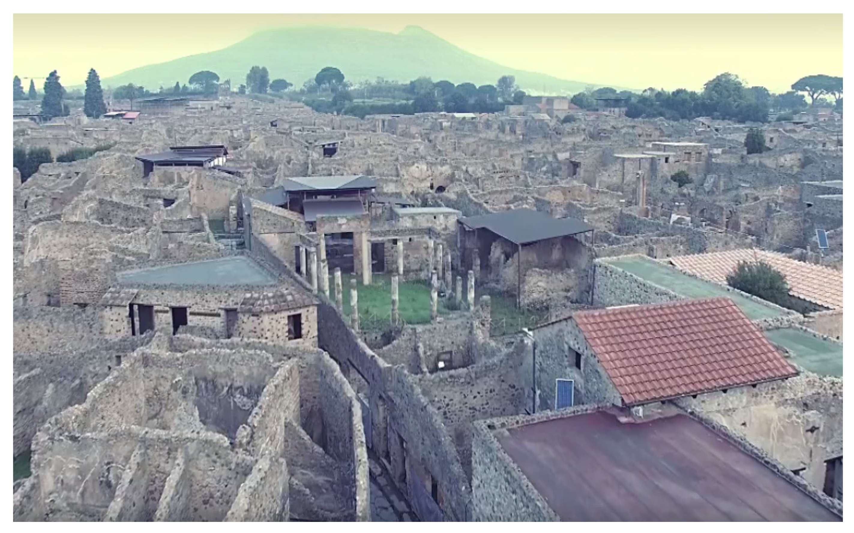
3. A Case Study: The Aggregate of Championnet Houses

The proposed design approach was applied in the rehabilitation project design of the aggregate of Championnet houses, in the ancient city of Pompeii, Italy. This part of the city of Pompeii was subjected to extensive rehabilitation works in the period 2015–2017 inside the project Grande Progetto Pompei. Figure 3 presents the area before the restoration and rehabilitation works.
In the following, the principal outlines of the project are shown.
In order to preserve the ancient decorative surfaces, a new roof, characterized by a steel structure and Corian slabs, was built over the ancient masonry walls as shown in Figure 4. These design decisions were conditioned by the presence of some precious mosaic decorated floors that needed protection, and their extensions did not allow for the design of a roof standing on a separate structure, which would be too invasive in the archaeological space. The extensive damage level and the limited thickness of the walls have gained great attention in the design of the rehabilitation works. Following the proposed design approach in Figure 2, the final design was reached after four extensive testing campaigns, before and during the execution phase. In the following, the experimental campaigns, the model, the performed analysis, and the design solutions are discussed.
The rehabilitation and restoration works have focused on a wide area located in Insula 3 of Regio VIII, between Venere’s Sanctuary and the Roman thermal baths of Sarno. This part of the ancient city of Pompeii has three buildings for administrative and public use, and a series of ancient houses located on a cliff with a panoramic view of the sea. This part of the Roman city has a long and complex history that started in the 2nd century B.C., but successively, the buildings have been subjected to several transformations until 79 A.D., when they were covered by the volcanic materials erupted by Vesuvius. Primarily, as proposed in Section 2, the available documentation on the aggregate of houses has been collected and a measurement survey on the structures conducted. During the excavation works, the level of knowledge was improved with supplementary experimental campaigns.
Section 3.1 is dedicated to the experimental campaign, oriented toward revealing the stratigraphy and foundation, the material characteristics, and the structural damages, and finally, to assess the efficiency of the rehabilitation works. This information is necessary for the structural modeling and the final structural detailed design presented in Section 3.2. The discussion on the efficiency of the proposed solution is then discussed in the Section 3.3.

3.1. The Experimental Campaigns

The rehabilitation design of ancient structures always needs an extensive experimental campaign that aims to learn the geological and geotechnical characteristics of the soil foundation, the nature and location of the foundations, the material features, the damage level of all elements, the types and efficacy of connections between walls, and the construction details. Simple visual inspection is often not sufficient to obtain a complete knowledge of the soil and structures. The use of non-destructive testing [16,17,18] is a valuable tool to understand the structure and build a reliable model that will allow for the structural behavior to be simulated [19,20]. At an archaeological site, some testing and excavation can be performed during the work execution to complete the design process. In some cases, the efficiency of the proposed rehabilitation solutions [19] can be usefully evaluated through experimental testing during execution.
In the proposed example, ground penetrating radar, sonic tests [17,18,19] with tomography image results, combined with material testing on mortar and natural stones of the masonry walls, has allowed for the assessment of the effectiveness of the strengthening technique. This information produced an improvement in the design process and a refined localization of the consolidation works. In the following paragraphs, the different tests are discussed.

3.1.1. The Subsoil Stratigraphy and Foundation Analysis

The soil under the Championnet houses in Regio VIII was investigated. According to the data of the performed surveys and the stratigraphy reported by the archaeological excavation essays, the archaeological area can be characterized from the lithological sequence detailed in the following Table 1.
In order to understand the effective load capacity to be transferred to the ground, during construction works, some excavation essays can be made to identify the depth, nature, and dimensions of the foundation. The excavations revealed that the ancient foundations had underground walls that were thicker 0.30–0.40 m more than the ones in the upper part, and with a more intact and less degraded structure. The excavations revealed that the foundation was not deeper than one meter from the soil surface. The dimensions and depth of these foundations make the structures vulnerable to static and seismic load. For these reasons, the structural skeleton of the new roofs placed on the ancient masonry walls was made of light materials in order to do not overload the thin foundations and the bearing soil of these ancient structures. Figure 5 shows an excavation to reveal the foundation.

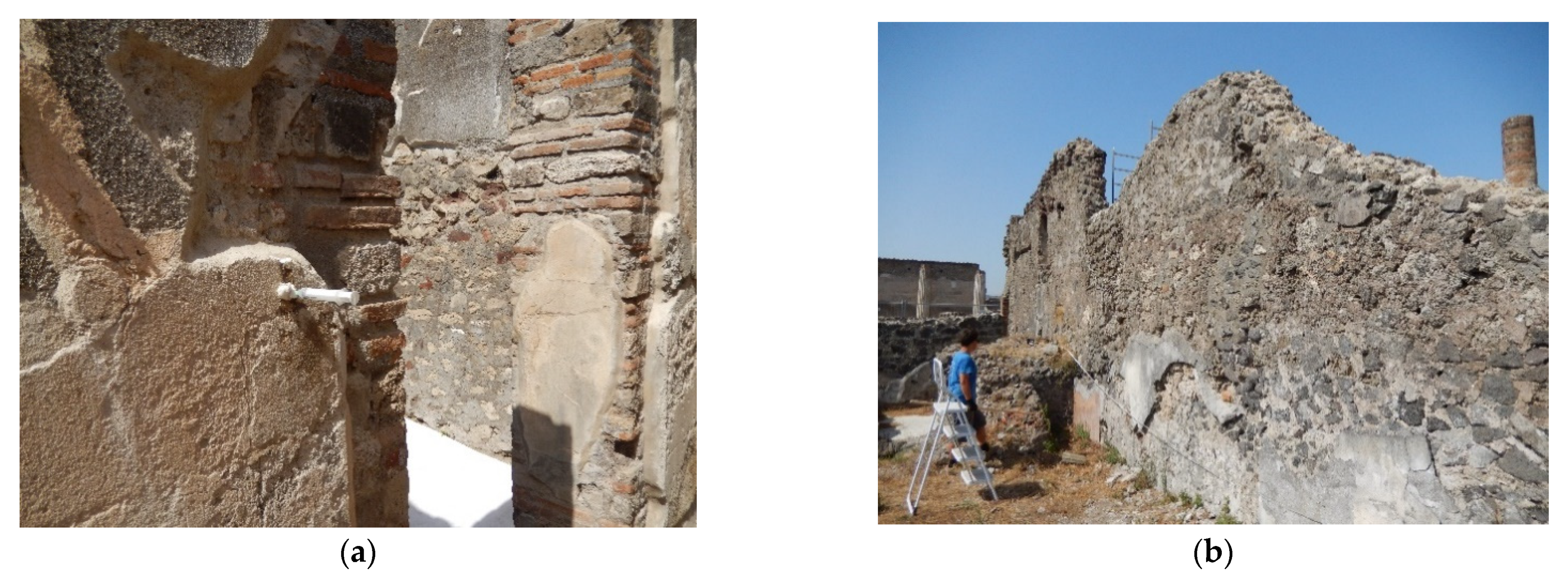
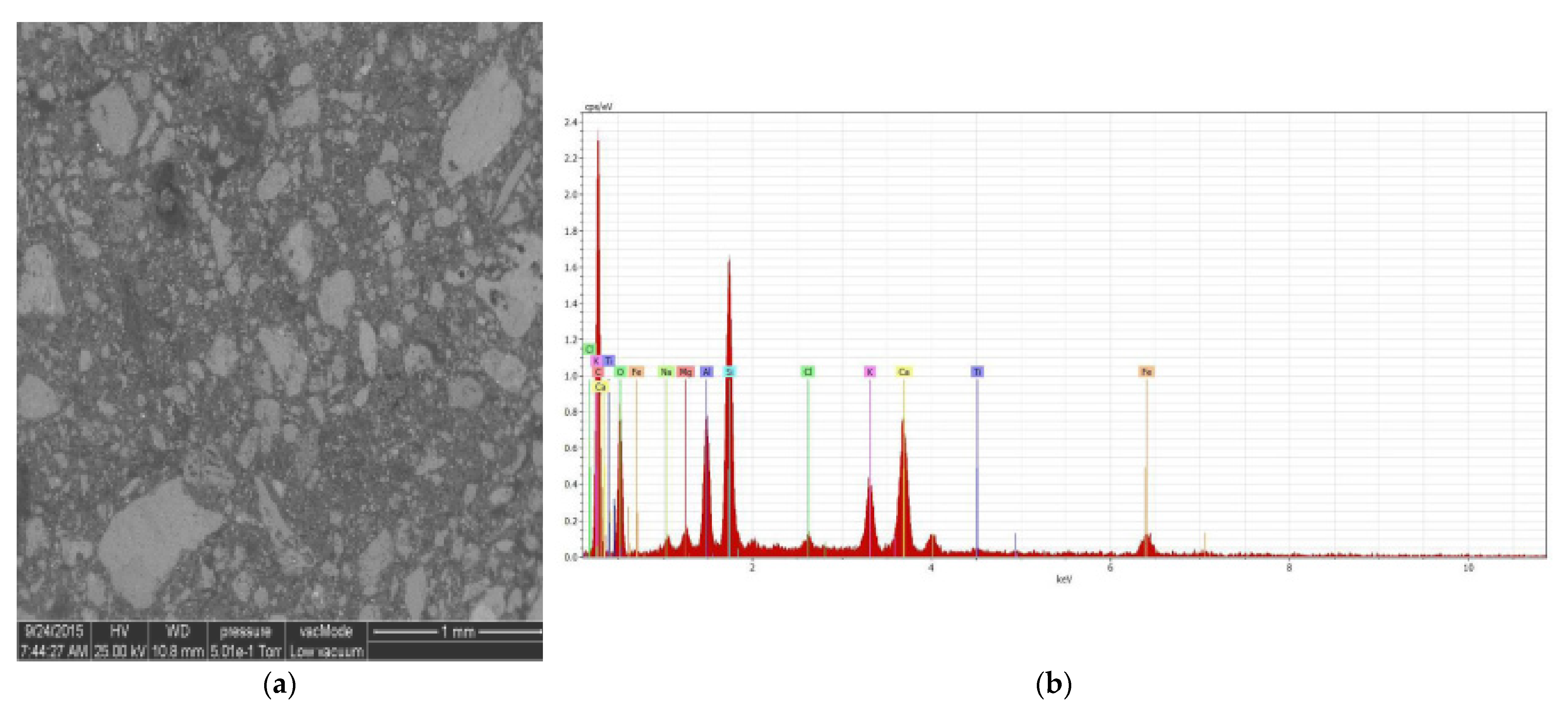
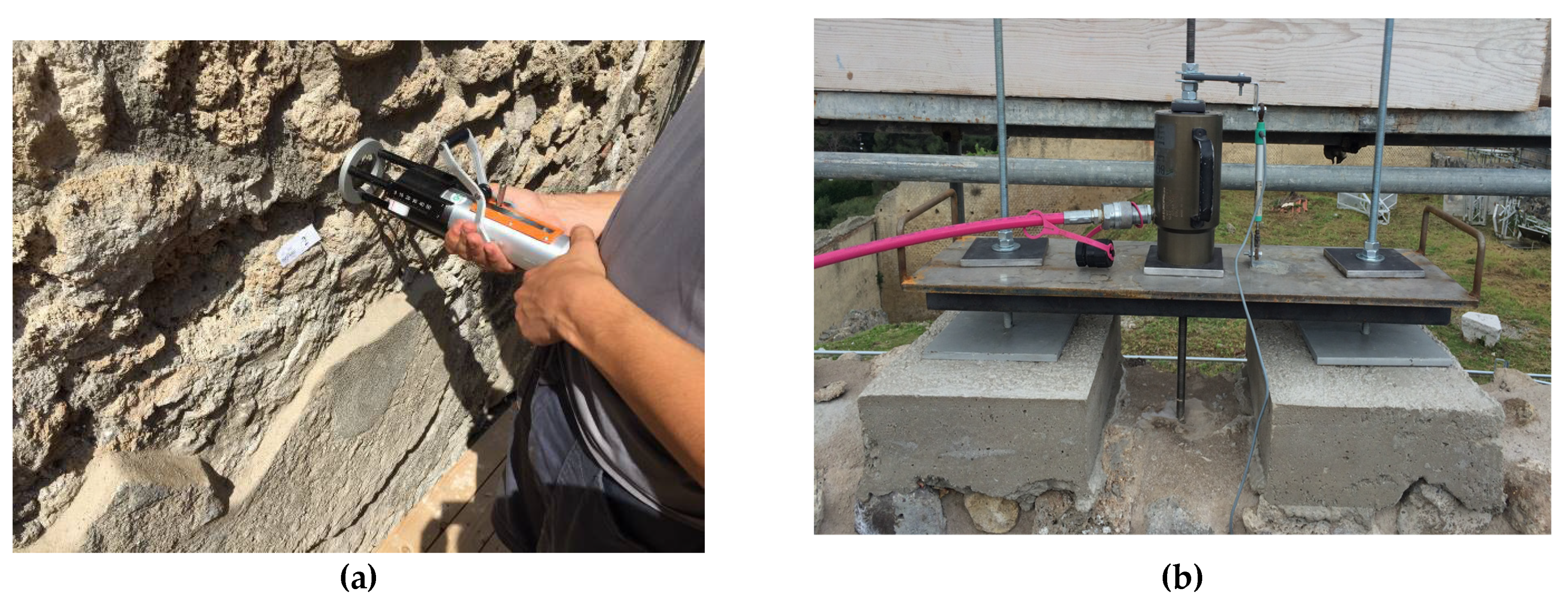
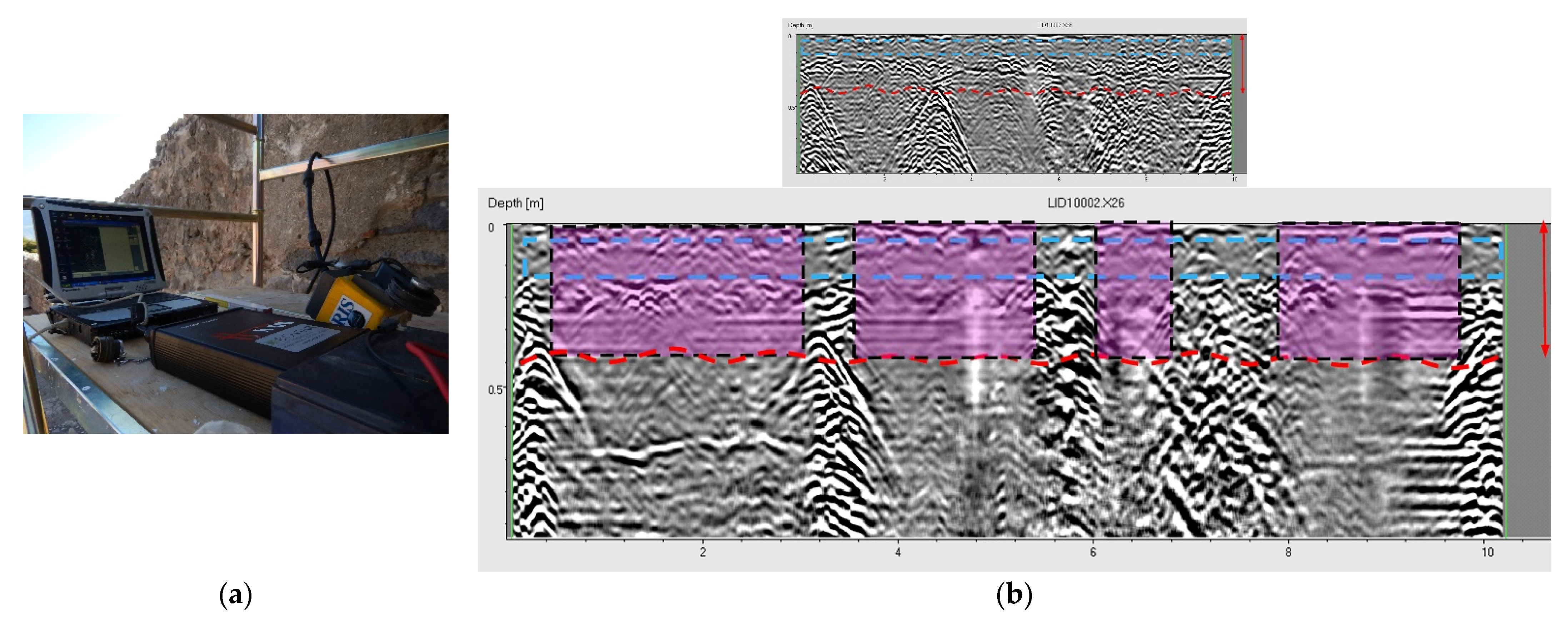
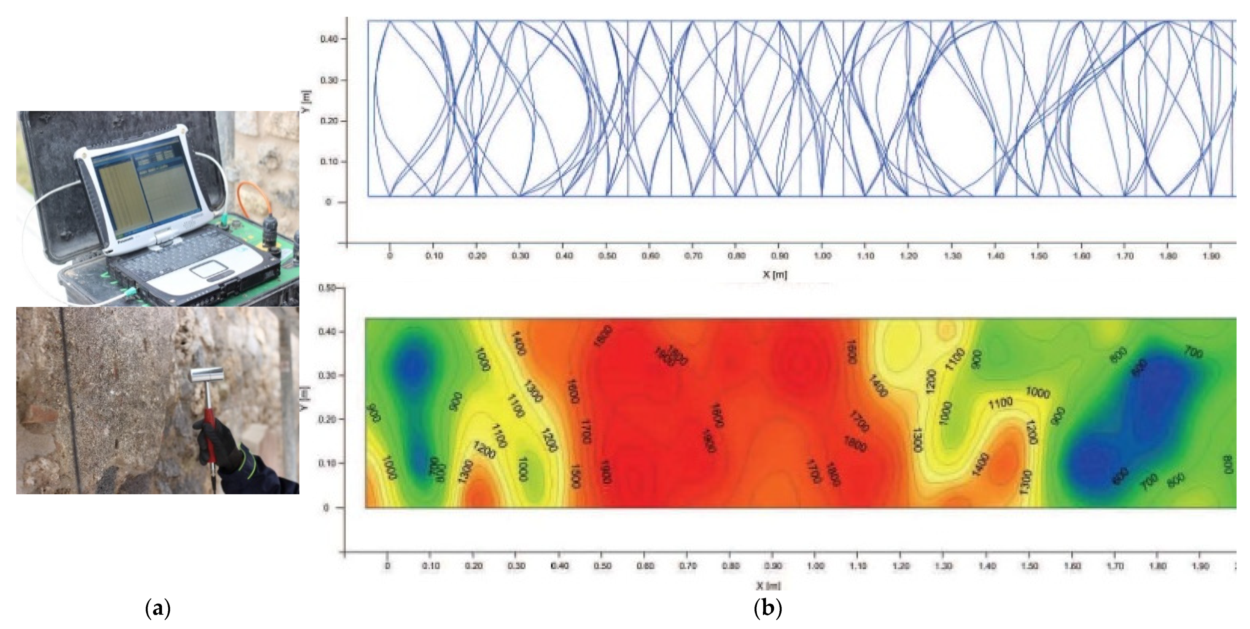
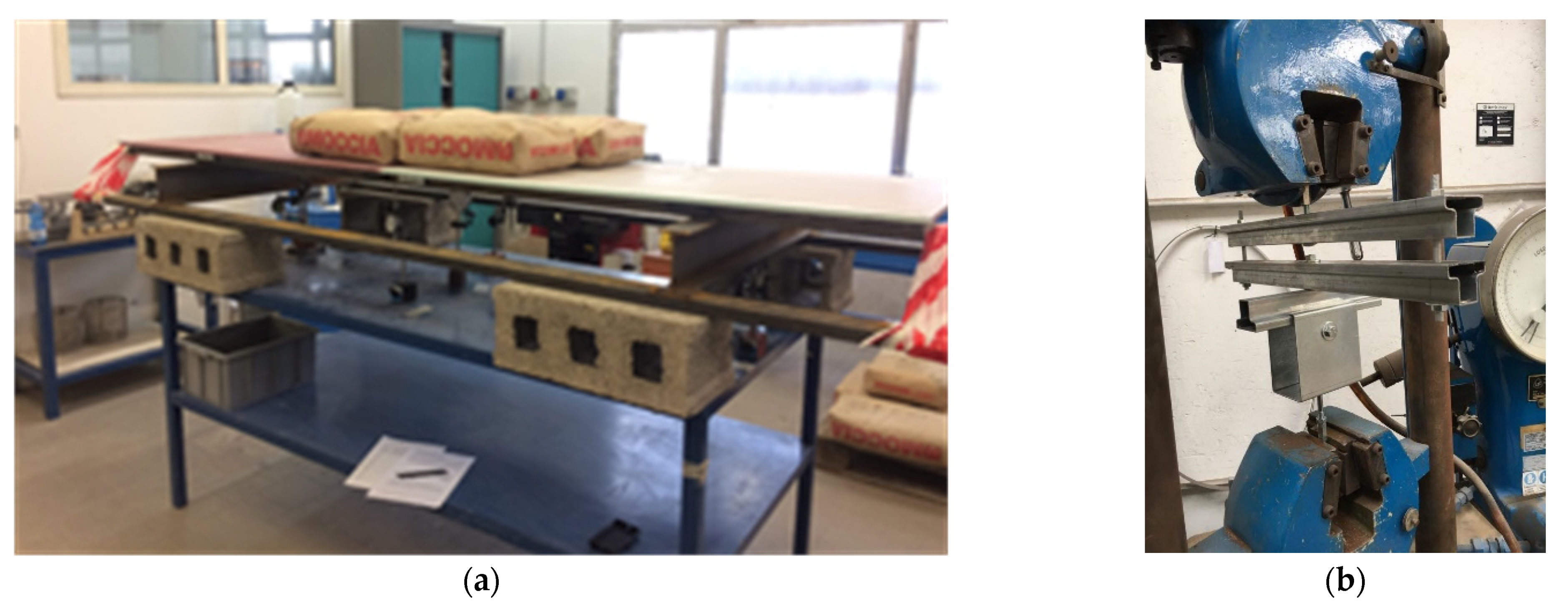
3.1.2. The Characteristics of Ancient Masonry Walls

The archaeological constructions at the ancient Pompeii settlement are characterized by different wall systems in terms of construction technologies, geometries, and materials. In particular, natural stones and bricks are both used; the walls in Figure 6 are made up of regular, but often irregular elements in terms of the shape and lithotypes.
Most masonry walls are of the type “opus incertum”, made of irregularly shaped stones with a more or less flat face. The stones used in the masonry were bound together with mortar. The smaller pieces were added between one stone and another. The whole wall was then sprinkled with a pouring of liquid mortar that was able to expand throughout the masonry. In some walls, the masonry structure is of the type “opus vittatum”, which constitutes bricks and small blocks (called “tufelli”). Sometimes, bricks are located in the edges and corners.
The chemical-physical characteristics and damage are extensively varied in the masonry walls, affecting stone elements and mortars. The masonry deterioration concentrated, especially in the first meter in height, even with the loss of elements (ashlar and mortar). In general, rain water and wind erosion have caused the most loss of material. The damage processes are related to the absorption, flow, and stagnation of rain water. In particular, the tops of the walls are subjected to degradation due to the erosion and the breakup of large tracts. Damage is often determined by the nature of the mortar; whenever the mortar is made up of a volcanic aggregate with a variable size of 3–4 cm lithic clasts and fine sands mixed with a low lime component or other binder, this composition made the mortar very vulnerable. The volcanic nature of the aggregate involves the absorption of rain water and the rapid saturation of the top of the walls. This imbibition process leads, over time, to consistent loss and erosion, especially at the top of the walls. In particular, the water absorption of the stones/bricks and the mortar of the walls yield desegregation, with consequent swelling, fracturing, and breaking of the masonry.
In order to acquire an appropriate level of knowledge necessary to the final design, four surveying campaigns were carried out during construction works. These campaigns have provided knowledge of the characteristics of the masonry materials. The characteristics of the masonry walls were investigated through testing stone specimens; seven types of different stones that characterize the masonry wall in Pompeii were subjected to compression tests. The specimens to be tested were collected in the original disaggregated material present in the area of Championnet in order to respect the material fabric. Table 2 shows the test results. In particular, the low compression strengths of some stones, called “tufo giallo” and “cruma” are shown with a compression strength of 3.4 and 6.2 MPa, respectively. These natural stones are very widespread in archaeological constructions in the area, so these low compression strengths affect the whole behavior of the masonry walls.
The analysis of old mortar has an important role in the preservation of architectural heritage, as soon as detailed knowledge about the materials used and construction techniques yields a program of repair works able to reduce the degradation processes. For this reason, the conservation level of the mortars and the characteristics of the material was evaluated through an electron microscope image in Environmental scanning electron microscope (ESEM) modality at low vacuum (see Figure 7a). The physical-chemical, mineralogical, and microstructural characterization was obtained as shown in Figure 7b. The matrix of the mortar was mainly characterized as a inhomogeneous calcite with the presence of lime (25%), the aggregates were mainly vulcanites (brown and reddish pozzolane) (92%), feldspar (3.8%), pyroxenes (3.2%), mono and polycrystalline calcite (0.7%), and micas (0.3%). The porosity of the binder was about 15% due to the presence of micro-cracking. This proves the vulnerability of the mortar to rain water, which yields desegregation and fracture.
A penetrometer test was also performed. The test measures the depth of penetration by inserting a steel needle into the mortar joint. Figure 8a shows the equipment that was used. The test, performed at fifteen points on ancient mortars, measures the penetration of the test needle and the results were interpreted by using correlation analysis in terms of the conservation state of the mortar and then in terms of the mechanical properties. The obtained penetration test results are reported in Table 3. Most values are often less than 0.4 N/mm2, which demonstrates the low resistance of the mortar joint.
Together with the tests conducted on the stones and bricks, the mortar tests allowed for the identification of the masonry compression strength. The correlation of these data with the ones on similar walls in another ancient house in Pompeii, where a flat-jacket test (single and double jacket) was performed, allowed the designer to choose a low value of 1 MPa for the compression strength of the masonry.
Figure 9 shows the radar test on the masonry walls, in particular, Figure 9a shows the equipment and Figure 9b the diagram results. This test has been used to check the efficiency of masonry consolidation through the grout injection technique and the insertion of basalt fibers inside the mortar joints, which is discussed in the next paragraph. The comparison of the radar diagrams showed evidence of the area of wall where the rehabilitation technique had been less effective, as a consequence, new consolidation work has been planned during the execution works in order to have homogenous structural density in the masonry wall.
Tomography images, obtained from the sonic test equipment composed of a hammer as exciter and a receiver of the generated waves (in Figure 10a the sonic test equipment), were obtained of selected sections of the walls. The elaboration of signals also allowed us to check the homogeneity of the inner part of the masonry walls and the efficiency of the rehabilitation works. Figure 10b shows the test results of a section of the wall, where both the trajectories of the signal and the tomographic image show the velocities of the waves.
In order to assess the efficiency of the steel bar and connection of the steel roof skeleton to the underneath walls, three pull-out tests were conducted during the construction phase. During the tests, a maximum load of 2600 daN was reached. This proved the efficiency of the grout injection technique that was used to lock the bar of the steel roof-skeleton inside the masonry walls. Figure 8b shows the pull-out test setup.

3.2. Structural Modeling and Detailed Design

The information collected through the experimental campaign was used to obtain a reliable structural model and to drive the settlement of new materials and devices to upgrade the structural performance under static and dynamic loading.

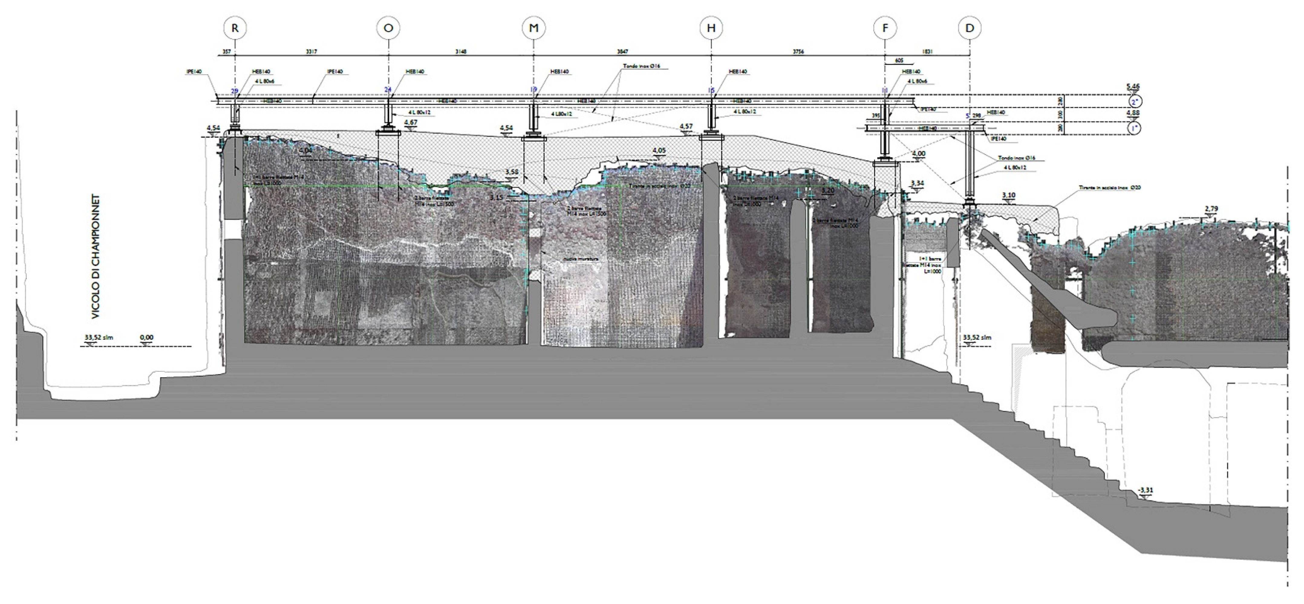
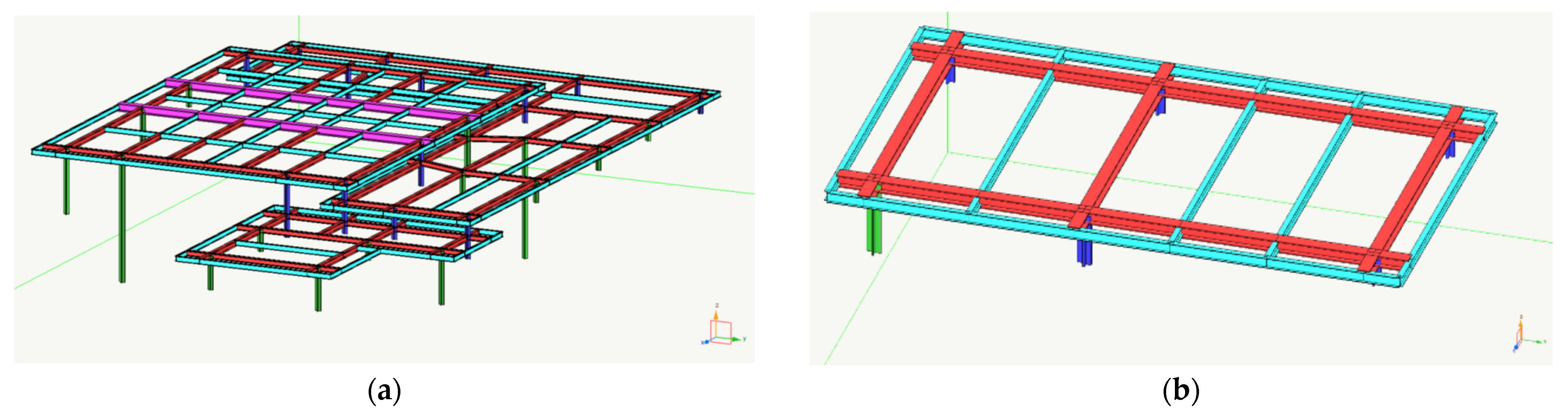
3.2.1. The Model and the Structural Design

The new structure was modeled with a spatial finite element model using the commercial software Nolian. The static and dynamic safety of the artifacts were verified by assessing the strength, functionality, and durability of the structural elements, in relation to the load conditions at the ultimate limit state and serviceability state, and taking into account the requirements and safety coefficients indicated by the current Italian codes [12]. The local behavior of the walls was evaluated by elementary models of the different structural elements by using the limit analysis for the principal collapse mechanisms.
The Italian guidelines for cultural heritage structures in seismic area focus on the criteria for assessing seismic safety and the effectiveness of the interventions. These guidelines consider the cultural heritage structure [11] in terms of the possibility of designing rehabilitation, repair or local interventions as defined in the Italian seismic code NTC2008. The only requirement is a comparison between the state before the intervention and the one after. In this project, the configuration before rehabilitation was strongly related to a state of masonry degradation and real connection among the structural elements, while after rehabilitation, the structural behavior depends on the effectiveness of the planned interventions, in this case, the efficiency of the fracture repairs, mortar joint repairs, grout injection, basalt fiber insertion, and on the stabilizing effect of the new roof. It can therefore be argued that the rehabilitation project takes the form of improving the characteristics of the materials constituting the masonry elements and the overall behavior of the individual wall with better interaction among the supporting masonry walls of the same roof.
The presence of new roofs, rigid in their plane, bind the top of the walls and transfer the horizontal seismic forces to the walls parallel to the actions. The main objectives of the project were the improvement of the reliability of the vertical elements to static loads, and to ensure durability and a reduction in the causes of degradation.
Nowadays, new technologies for repairing the structures, compatible with the historical fabric, are available on the market. Specifically, new materials such as basalt fibers inserted in the masonry joints, have been used together with natural grout injections to consolidate the structural masonry walls. This technique has been proven to highly increase the quality and resistance of the masonry walls in archaeological sites. The basalt fiber application is described in Section 3.2.2.
The need to rehabilitate and to protect the masonry walls from horizontal forces suggests the use of rubber bearing devices to be installed between a steel skeleton with a light covering surface made of Corian and the supporting walls.
In Section 3.2.3, the application of seismic devices in archaeological structures is presented in detail; this technology is very promising in the protection of masonry structures to contrast the damage due to horizontal loading. Historical buildings are usually characterized by relatively low height and high stiffness, which corresponds to a low period of vibration. For buildings located in seismically active zones, seismic isolation systems could be a very effective solution for improving the earthquake resistance of these structures. The main advantage of a seismic isolation system is that no structural elements should be added to the structure in order to strengthen it [25,26,27], while the traditional techniques, oriented to increase strength and ductility, are not always useful in the seismic rehabilitation of complex masonry structures. The aim to reduce seismic actions, thus avoiding significant damages to the structure and its contents even under strong earthquakes, yields successful results, since the devices can interfere moderately with the structure itself. The severe damage in masonry buildings due to earthquakes has shown the need to study new seismic protection techniques in order to guarantee the appropriate safety levels against earthquakes as well as the minimum impact on the material fabric. The Base Isolation System (BIS) balances the opposite requirements of structural safety and architectural preservation [28,29,30]. In the literature, there are few examples of the application of base-isolation to protect artifacts, in particular, its use at archaeological sites is even rarer.
Herein, the rubber bearings are installed between the masonry walls and a new steel roof to disconnect the roof from the masonry walls in order to protect the underneath ancient walls from the horizontal forces.

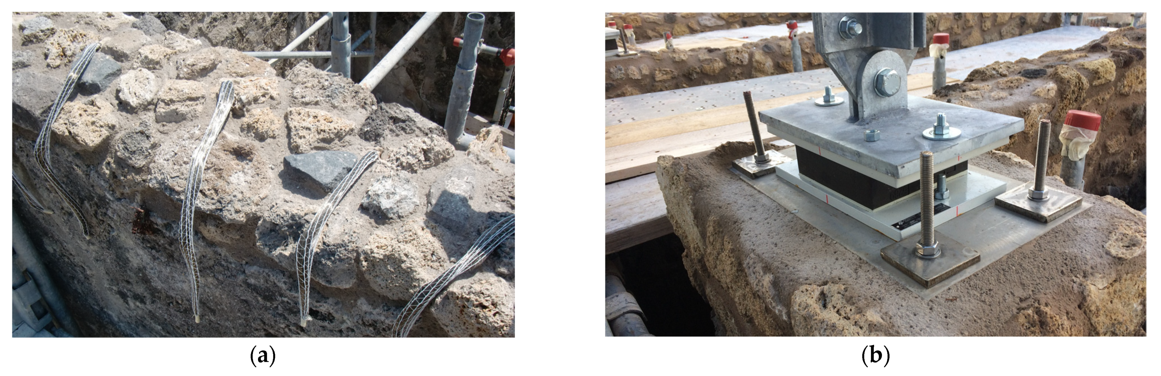
3.2.2. Basalt Fiber Use

The masonry damage state is characterized by deteriorated mortars and the presence of holes and alveolation. For these reasons, the ancient walls have been consolidated by grout injection as well as the insertion of basalt fiber nets and ropes [31,32,33]. The choice of natural fibers (Figure 11a) such as basalt in structural rehabilitation is currently a new technique, particularly suited to cultural heritage, as soon as basalt is a natural material with a high level of compatibility with the historical fabric. The use of these fibers, as a connection between the existing masonry and the reconstructed portion, is particularly effective for these ancient walls, as even when burdened by roofing, they increase the structural continuity. Basalt fiber robes have been also introduced inside the mortar joints in the wall facades in order to increase the resistance of all systems made of stones and mortar. The connectors in basalt fibers are characterized by 54 fibers, a warp thickness of 6.48 mm, warp density of 2.6g/cm3, and warp elastic modulus of 87 GPa. The fibers were inserted in the joint using a structural mortar with a compression strength after 28 days greater than 1.5 MPa, with rheoplastic characteristics made of natural hydraulic lime and selected aggregates.

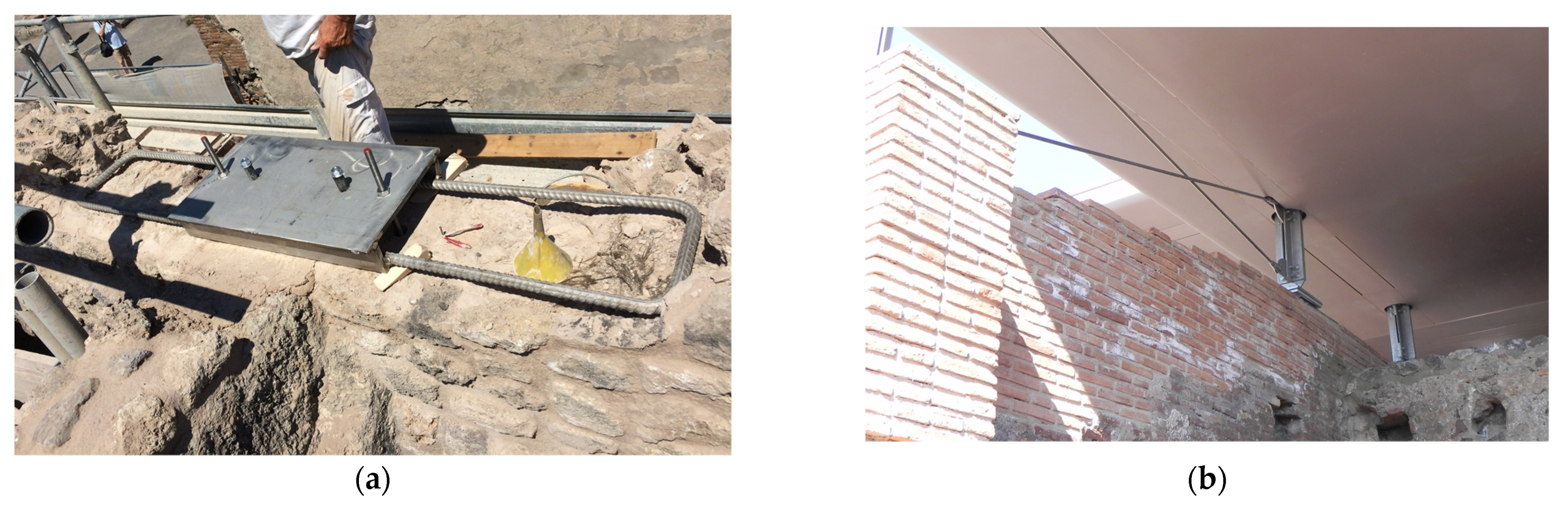
3.2.3. Rubber Bearing Devices

Elastomeric devices in reinforced neoprene were placed between the roof structure and the walls. The use of such devices is intended to protect the underlying wall by means of a horizontal shear force distribution among the walls. However, in general, these devices are normally used to protect the overlying structure.
The characteristics of the Elastofip 1.5EF 7.2 device produced by Fip Industriale (Figure 11b) are described in Table 4. The device is a rectangular block of rubber with the insertion of a number of horizontal steel laminated plates, vulcanized to the rubber, which increases the vertical stiffness and improves the stability under horizontal load. The bearings were designed according to European standard EN 1337-3 in which they are classified as type C bearings. The elastomer that forms the core was made of natural rubber of reinforcing plates class S355, while the anchoring counter plates were made of class S275.

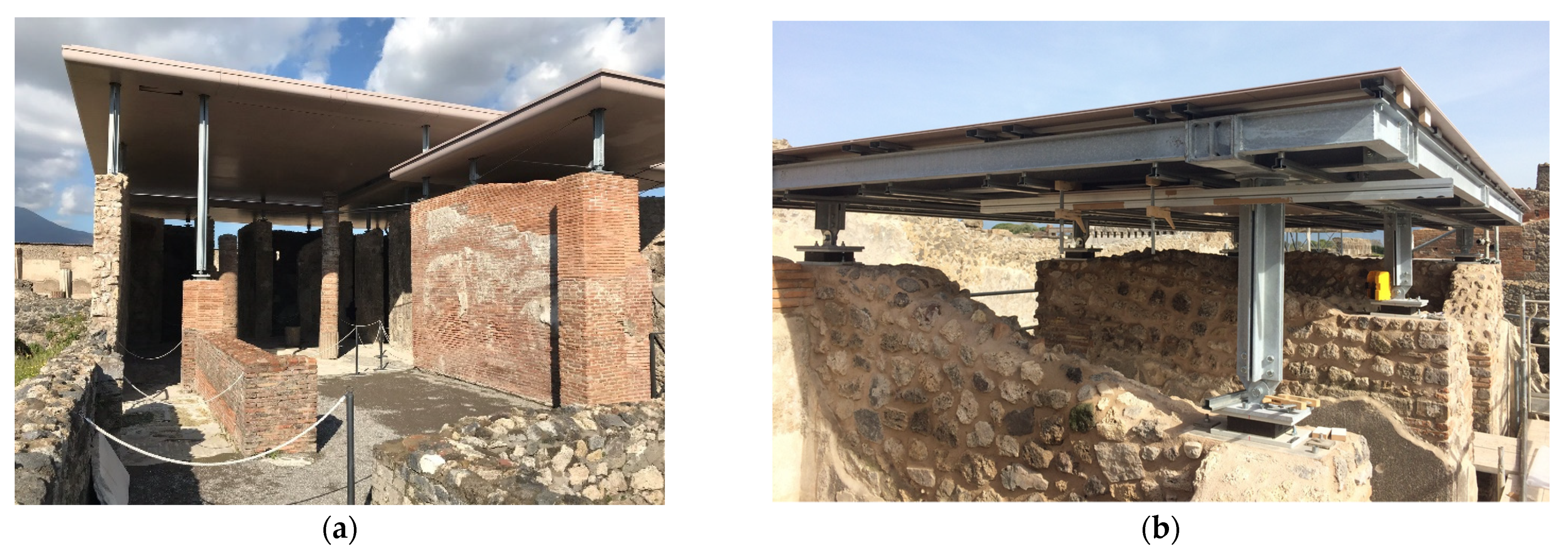
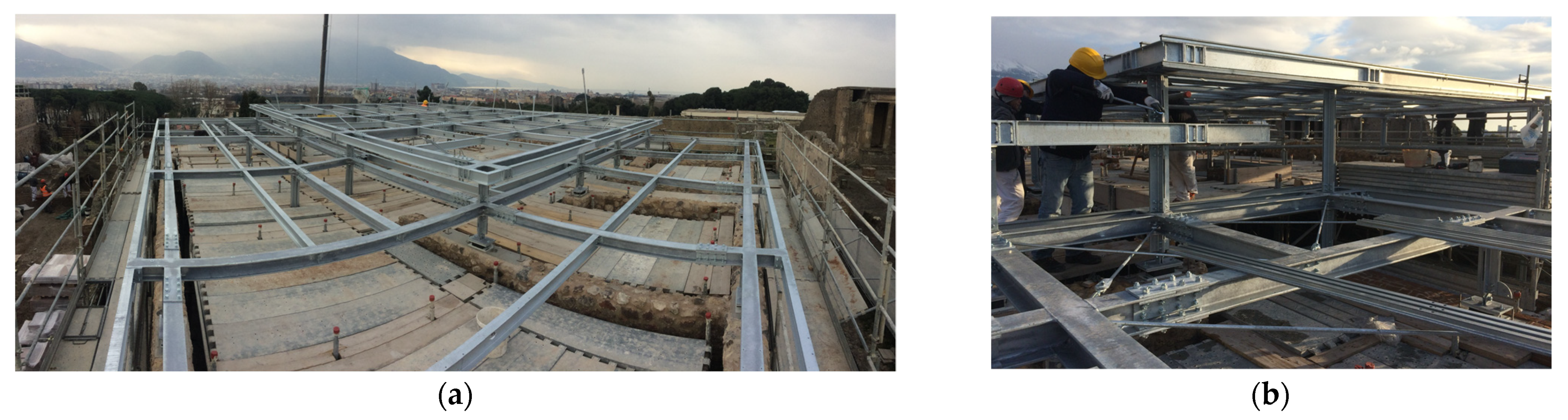
3.2.4. Steel Roof Skeleton

A steel skeleton and Corian slabs for the roof were chosen in order to limit the structural overweight (Figure 12) on the underneath walls. The atrium of the principal house (at numbers 1 and 2 Championnet Street) is about nine-meters-wide; for this reason, beams of considerable length had to be put in place (Figure 13, Figure 14 and Figure 15), but the Corian surfaces, characterized by a limit weight compared to other materials on the steel skeleton limit of the roof load on the ancient walls, avoiding high compression stresses in the masonry.
The problem of transmitting the load derived from the covering on the underlying masonry was solved by laying stainless steel plates anchored in the masonry with 2 m long bolted steel bars (Figure 14a). During the work execution, some tests were carried out to extract the anchors to check the adhesion strength and the slip resistance for the most severe load conditions such as the ascending wind, as previously discussed in Section 3.1.2. The results of these tests (Figure 8b) confirmed the effectiveness of the bar grouting, and the value of the adhesion strength between the bar and injected masonry was evaluated for the final structural design.

3.2.5. Roofing Made with Corian Slabs

The use of Corian plates for the realization of the covering mantle is a new application. Corian is a solid, nonporous, homogeneous surfacing material, composed of about 1/3 acrylic resin (also known as polymethyl methacrylate), and about 2/3 natural minerals. Corian is currently used for the construction of the facades of buildings.
Corian was chosen as the material for the roof slabs since this material is characterized by a high strength (flexural modulus of 8800 MPa, flexural strength of 71 MPa, tensile strength of 47 MPa, compressive strength of 119 MPa) with a limited weight. This agrees with covering the rooms with a light roof in order to avoid overloading of the ancient masonry walls.
The slabs have been the object of laboratory tests, the structural resistance to flexural actions has been proven, moreover, the connection of the covering layer (the extrados and the intrados of the metallic carpentry) has been the object of test investigations to verify their resistance during the operating phase and in rare load conditions such as the future maintenance phases. Figure 16 shows the test design and the execution of the laboratory test on Corian slabs, in particular, the flexural text in Figure 16a and the tensile test on the connection between the steel skeleton and the slab in Figure 16b.

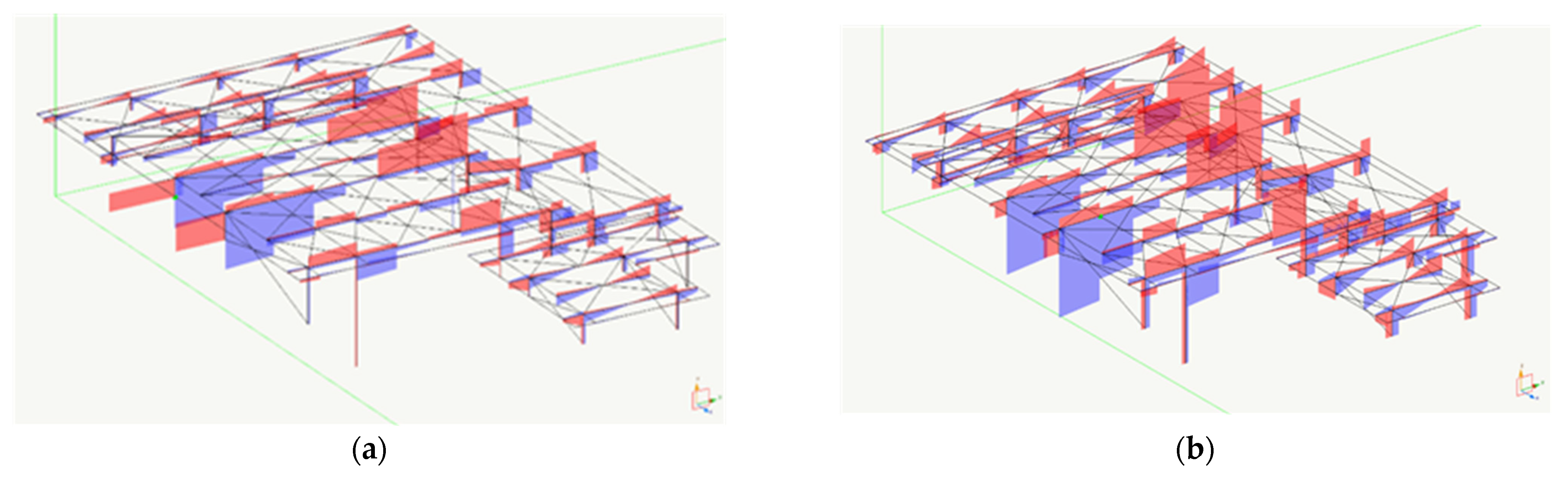
3.3. Structural Analysis

The model of the new roof was upgraded on the basis of the structural experimental results. The spatial model of the two roofs at civic number 1, 2, and 3 is shown in Figure 17.
At the base of the columns, the bearing device was modeled with elements having the stiffness of the Elastofip 1.5 EF 7.2. The structural detail was designed according to Italian seismic code NTC2008 [12]. The local bearing capacity of the masonry walls were verified according to Eurocodes and the possible overturning mechanisms were assessed according the limit analysis [16]. Figure 13 shows the structural design of the details, while Figure 14 and Figure 15 show the structural elements on place during construction.

Efficiency Analysis

The efficiency of the structural designed was performed. In the following, a comparison between the isolated structure at the base and a fixed base structure (the same structure modeled with interlocking constraints at the base) is presented, in order to show the benefits induced by the rubber bearing device installation, in terms of shear stresses at the base of the column and at the top of the underlying walls. First, introducing the bearing devices registered a shift in the first natural period of the structure. The result comparison showed a 424% reduction in shear in the base isolated structure (see Figure 18 and Table 5).

4. Conclusions

A rehabilitation design on archaeological structures generally needs numerous information regarding materials, connections, structural elements, and details that are not often known at the design stage, because some parts of the structures could be buried or inaccessible. Furthermore, the effectiveness of the planned consolidation technique, influenced by the variability of ancient material characteristics, could affect the efficiency of the planned intervention. This uncertainty can be solved during the execution works. For these reasons, a conceptual design approach for an archaeological settlement has been proposed that differs from the methodology that is used in ordinary historical buildings. This proposed approach allows for a reduction in the uncertainty at the design stage.
This methodology has been applied in the rehabilitation design of an ancient aggregate of houses in Pompeii, where the minimum intervention principle and the need to conserve the historic fabric are of priority importance. Additionally, the structural safety and the code requirements should be taken into account considering that these buildings are open to the public. Exhaustive knowledge of the materials’ properties and structural details were obtained with four experimental testing campaigns that allowed us to upgrade the structural model, and the design was the object of an iterative but rigorous approach. In the case study, new technologies for masonry repair and seismic protection of the structures were proposed, and their efficiencies were proven by experimental and numerical analyses. In particular, basalt fibers with grout injection were used to consolidate the ancient masonry walls. The protection of the ancient structures against horizontal forces was obtained through the rubber bearings installed between the new roof and the underlying masonry walls. A new material, Corian, was used on the roof as a covering mantle. Future steps of this research will be the assessment of the durability of the interventions in order to evaluate the effective needs of the maintenance of these structures.

Author Contributions

Conceptualization, V.C. and A.Z.; methodology, V.C. and A.Z.; formal analysis, V.C. and A.Z.; investigation, V.C. and A.Z.; writing—original draft preparation, V.C. and A.Z.; All authors have read and agreed to the published version of the manuscript.

Funding

This project was funded by PON “Cultura e Sviluppo”–FESR 2014–2020.

Data Availability Statement

Data is contained within the article.

Acknowledgments

The authors acknowledge the General Managers of Grande Progetto Pompei. Massimo Osanna, Giovanni Nistri, Luigi Curatoli, and Mauro Cipolletta and all of the members of the team involved in the realization of the construction works of GPP 23 24, financed by the European Commission, whose collaboration allowed us to obtain the successful application presented in the paper. In particular, we wish to thank Caterina Cicirelli, the construction manager arch. Letteria Spuria, and the construction company RWS srl and the company Palladio srl that has performed the tests.

Conflicts of Interest

The authors declare no conflict of interest.

References

  1. Fumo, F.; Calvanese, V.; di Gangi, G.; Ribera, F. Traditional Masonry in Campania Italy, Conference Historic Structures 2001; Kolozsvàr Editura Utilitas Publisher: Konyvkiadò, 43-58, Cluj-Napoca, Romania, 2001; ISBN 9739377254. [Google Scholar]
  2. Pagano, M. Metodologia dei Restauri Borbonici a Pompei ed Ercolano. Metodol. Restauri Borbonici Pompei Ercolano; L’Erma di Bretschneider: Rome, Italy, 1991; pp. 169–191. (In Italian) [Google Scholar]
  3. Salassa, C.M. Le coperture di restauro a Pompei. Riv. Studi Pompeiani 1999, 10, 91–115. (In Italian) [Google Scholar]
  4. Flamini, M.G.; Prisco, G.; Capanna, F.; Guglielmi, A.; Caligaris, M.O.; Salerno, C.S. L’Istituto Centrale per il Restauro a Pompei: Interventi nella Casa dei Vettii e nella casa VI 15, 2. Riv. Studi Pompeiani 2000, 11, 252–262. (In Italian) [Google Scholar]
  5. Bergamasco, I.; Gesualdo, A.; Iannuzzo, A.; Monaco, M. An integrated approach to the conservation of the roofing structures in the Pompeian Domus. J. Cult. Herit. 2018, 31, 141–151. [Google Scholar] [CrossRef]
  6. Laurenti, M.L. Le Coperture delle Aree Archeologiche; Gangemi Editore: Rome, Italy, 2007; ISBN 884920940-1. (In Italian) [Google Scholar]
  7. Boca, A.; Toader, T.P.; Mircea, C. Romanesque Historical Monuments Reconstruction by Using Original Materials and Recycling of Those That Have Lost Their Historical Value. Proceedings 2020, 63, 7. [Google Scholar] [CrossRef]
  8. Valluzzi, M.R. Requirements for the Choice of Mortar and Grouts for Consolidation of Three-Leaf Stone Masonry Walls; Workshop Repair Mortars for Historic Masonry; RILEM Publications SARL: Paris, France, 2009; pp. 382–397. [Google Scholar]
  9. Bras, A.; Heriques, F.M.A. Natural Hydraulic Lime Based Grouts—The Selection of Grout Injection Parameters for Masonry Consolidation, Construction and Building Materials; Elsevier: Amsterdam, The Netherlands, 2012; Volume 26, pp. 135–144. [Google Scholar]
  10. Di Miceli, E.; Bianco, V.; Filetici, M.G.; Monti, G. Retrofit of a Collapsed Masonry Gallery with Historical Value: Preliminary Study of Alternative Solutions and Retrofitting Strategies Paper 4365 New Trend on Integrity, Reliability and Failure. In Proceedings of the Conference IRF 2016, Porto, Portugal, 24–28 July 2016. [Google Scholar]
  11. Linee Guida per la Valutazione e la Riduzione del Rischio Sismico del Patrimonio Culturale con Riferimento alle Norme Tecniche per le Costruzioni di cui al Decreto del Ministero delle Infrastrutture e dei Trasporti del 14/01/2008; Gazzetta Ufficiale: Rome, Italy, 2011; n. 47, 26/02/2011. (In Italian)
  12. Norme Tecniche delle Costruzioni (NTC2008), D.M. 14/01/2008, Italy; Gazzetta Ufficiale: Rome, Italy, 2008; n.29 e n.30 04/02/2008. (In Italian)
  13. Spyrakos, C.C. Bridging performance based seismic design with restricted interventions on cultural heritage structures. Eng. Struct. 2018, 160, 34–43. [Google Scholar] [CrossRef]
  14. Monti, G.; Valente, G. Archaeology, Cryptoportici, Hypogea, Geology, Geotechnics, Geophysics. In Proceedings of the Interna-tional Workshops Dynamic Interaction of Soil and Structure, DISS15, Rome, Italy, 12–13 November 2015; ISBN 978-88-940114-2-5. [Google Scholar]
  15. Bartelletti, R.; Fiorentino, G.; Lanzo, G.; Lavorato, D.; Marano, G.C.; Monti, G.; Nuti, C.; Quaranta, G.; Squeglia, N. Be-havior of the Leaning Tower of Pisa: Analysis of Experimental Data from Structural Dynamic Monitoring. Appl. Mech. Mater. 2016, 847, 445–453. [Google Scholar] [CrossRef]
  16. Silva, B.; Dalla-Bennetta, M.; da Ponto, F.; Valluzzi, M.R. Compression and sonic Tests to Assess effectiveness of grout injection on three-leaf stone masonry walls. J. Archit. Herit. Conserv. Anal. Hist. 2014, 8, 408–435. [Google Scholar] [CrossRef]
  17. McCann, M.C.F. Review of NDT Methods in the Assessment of Concrete and Masonry Structures, NDT & E International; Elsevier: Amsterdam, The Netherlands, 2001. [Google Scholar]
  18. Da Ponto, F.; Valluzzi, M.R.; Claudio-Modena, C. Use of sonic tomography for the diagnosis and the control of intervention in historic masonry building. In Proceedings of the Non-Destructive Testing in Civil Engineering, International Symposium, Berlin, Germany, 16–19 September 2003. [Google Scholar]
  19. Zambrano, A.; Rota-Rossi-Doria, P.; Tommasini, M. Identification of masonry by impact and ultrasonic test. In Proceedings of the International Symposium of Non-Destructive Testing in Civil Engineering (NDT-CE), Berlin, Germany, 26–28 September 1995; pp. 401–440. [Google Scholar]
  20. Moropoulou, A.; Kyriakos, C.; Labropoulos-Ekaterini, L.; Delegou, T.; Karoglou, M.; Bakolas, A. Non-destructive techniques as a tool for the protection of built cultural heritage. Constr. Build. Mater. 2013, 48, 1222–1239. [Google Scholar] [CrossRef]
  21. Di Gangi, G.; Monti, G. Regeneration and Structural Strengthening of the Fortress of Arnara, Latium, Italy. Int. J. Arch. Heritage 2016, 10, 1041–1054. [Google Scholar] [CrossRef]
  22. Aprile, A.; Benedetti, A.; Grassucci, F. Assessment of Cracking and Collapse for Old Brick Masonry Columns. J. Struct. Eng. 2001, 127, 1427–1435. [Google Scholar] [CrossRef]
  23. Penna, A.; Lagomarsino, S.; Galasco, A. A nonlinear macroelement model for the seismic analysis of masonry buildings. Earthq. Eng. Struct. Dyn. 2014, 43, 159–179. [Google Scholar] [CrossRef]
  24. Diaferio, M.; Foti, D.; Sabbà, M.F.; Lerna, M. A procedure for the seismic risk assessment of the cultural heritage. Bull. Earthq. Eng. 2021, 19, 1027–1050. [Google Scholar] [CrossRef]
  25. Lerna, M.; Sabbà, M.F.; Diaferio, M.; Carnimeo, L.; Ivorra, S.; Foti, D. Seismic risk assessment of a medieval tower: The case study of Craco. In Proceeding of the XI International Conference on Structural Dynamics-Eurodyn 2020—Streamed, Athens, Greece, 23–26 November 2020. [Google Scholar]
  26. Iskhakov, I.; Ribakov, Y. Using seismic isolation systems for retrofitting historic buildings. Reg. Airports 2012, 62, 159–169. [Google Scholar] [CrossRef] [Green Version]
  27. Clemente, P.; de Stefano, A.; Zago, R. Seismic isolation in existing complex structures. In Proceedings of the 15th World Conference on Earthquake Engineering, Lisbon, Portugal, 24–28 September 2012. [Google Scholar]
  28. Cuomo, G.; de Luca, A.; Mele, E. Design Aspects in Seismic Isolation: Application to Retrofit Churches. Int. J. Arch. Heritage 2008, 2, 247–273. [Google Scholar] [CrossRef]
  29. Kelly, J.M. Aseismic base isolation: Review and bibliography. Soil Dyn. Earthq. Eng. 1986, 5, 202–216. [Google Scholar] [CrossRef]
  30. Clemente, P.; de Stefano, A. Application of seismic isolation in the retrofit of historical buildings. ERES 2011, 1, 41–52. [Google Scholar] [CrossRef] [Green Version]
  31. Asprone, D.; Cadoni, E.; Iucolano, F.; Prota, A. Analysis of the strain-rate behavior of a basalt fiber reinforced natural hydraulic mortar. Cem. Concr. Compos. 2014, 53, 52–58. [Google Scholar] [CrossRef]
  32. Iucolano, F.; Liguori, B.; Colella, C. Fibre-reinforced lime-based mortars: A possible resource for ancient masonry restoration. Constr. Build. Mater. 2013, 38, 785–789. [Google Scholar] [CrossRef]
  33. Pauletta, M.; di Luca, D.; Russo-Fumo, E.C. Seismic rehabilitation of cultural heritage masonry buildings with unbounded fiber reinforced elastomeric isolators (U-FREIs)—A case of study. J. Cult. Herit. 2018, 32, 84–97. [Google Scholar] [CrossRef]
Figure 1. Design process on a historical building.
Buildings 11 00167 g001
Figure 2. Design procedure on masonry structures at archaeological sites.
Buildings 11 00167 g002
Figure 3. The aggregate of Championnet houses before restoration.
Buildings 11 00167 g003
Figure 4. The new roof in the Championnet area. (a) View of the new roof. (b) Steel structures before coating.
Buildings 11 00167 g004
Figure 5. Foundation. (a) Excavation at Regio VIII. (b) The localization of the excavation (reported in red).
Buildings 11 00167 g005
Figure 6. The masonry walls in the Championnet area. (a) A sample of the variety of masonry walls. (b) A long structural masonry wall before rehabilitation, with evidence of the alveolation and damage.
Buildings 11 00167 g006
Figure 7. (a) Mortar image with Environmental scanning electron microscope (ESEM) modality low vacuum (LV); (b) energy dispersive spectroscopy (EDS) analysis on the mortar.
Buildings 11 00167 g007
Figure 8. Tests. (a) Penetration test on mortar; (b) Pull-out test on a steel bar, connection the roof on the masonry walls.
Buildings 11 00167 g008
Figure 9. (a) Radar test on a structural wall: the equipment. (b) Comparison test before and after rehabilitation.
Buildings 11 00167 g009
Figure 10. (a) Equipment for tomography tests. (b) Tomography test results on a plan section of an ancient wall.
Buildings 11 00167 g010
Figure 11. (a) Basalt fiber ropes in the masonry top wall. (b) The rubber support device.
Buildings 11 00167 g011
Figure 12. Executive section with cover, supports, and walls.
Buildings 11 00167 g012
Figure 13. Structural design. (a) Detail of the roofs in plane. (b) Joint detail.
Buildings 11 00167 g013
Figure 14. (a) Steel slab detail. (b) Steel rob detail.
Buildings 11 00167 g014
Figure 15. (a) Steel beams during structural work. (b) Details under construction.
Buildings 11 00167 g015
Figure 16. The laboratory testing on the upper and bottom surface of the Corian slabs (a). The flexural test in laboratory (b).
Buildings 11 00167 g016
Figure 17. The structural models of the roofs. (a) Championnet n.1-2; (b) Championnet house at n.3.
Buildings 11 00167 g017
Figure 18. Comparison in terms of shear. (a) Base isolated structure. (b) Fixed base structure.
Buildings 11 00167 g018
Table 1. Soil stratigraphy.
LayerThickness
(m)
Description
11Modern agricultural land
21Repeated layers of ashes, lapilli
32.5Surge stratified deposit consisting of ashes, lapilli, lithic levels, related to the final phase of the eruption of 79 A.D.
40.20Ashes and pumice fragments
53Pumice unit organized into two subunits due to the central phase of the eruption of 79 A.D.: on the top the typical gray pumice, lapilli and clasts; in the bottom unit lapilli, pumice and clasts.
60.30Base ash units relevant to the initial phase of the 79 A.D.
74.0Complex of paleosols, alluvium colluves, soils, and anthropic deposits dated to 79 A.D.
85.0Lava units and their alteration coulters, sometimes separated by epiclastites, due to eruption activities prior to 79 A.D.
Table 2. Compression test on the masonry stones.
SampleNo. of TestsVolumic Mass
(Kg/m3)
Strength
(MPa)
Brick214845.4
Tufo giallo39923.4
Calcare di Sarno (Travertino)312792.0
Tufo grigio3131512.8
Lava grigia3241236
Schiuma lavica (cruma)28676.2
Table 3. Penetration test results on mortar.
No. of TestMortar Penetration (mm)Compression Strength (MPa)
125<0.4
2190.6
333<0.4
427<0.4
5180.7
628<0.4
726<0.4
8180.7
925<0.4
1026<0.4
11210.4
1225<0.4
1326<0.4
1423<0.4
15100.6
Table 4. Rubber bearing characteristics.
Limit StateValue
Ultimate limit stateMaximum compressive vertical load 7100 daN
Maximum vertical Tensile load 1500 daN
Serviceability limit stateMaximum compressive vertical load 200 daN–22 daN
Maximum vertical Tensile load 0 daN
Horizontal force 200 daN
Table 5. Maximum shear comparison.
Column n.ElementCombMaximum Shear V (daN)
Base Isolated Structure
Maximum Shear V (daN)
Fixed Base Structure
94L80×62013621813
124L80×12298234313
Publisher’s Note: MDPI stays neutral with regard to jurisdictional claims in published maps and institutional affiliations.

