1. Introduction
False ceilings, or dropped ceilings, are often used in construction and architecture as a zone to store and hide unsightly [
1,
2] but essential building infrastructure such as heating, ventilation ducts and air-conditioning (HVAC), electrical wiring and plumbing systems [
3]. Besides helping to regulate thermal performance [
4] and acoustic performance [
5,
6], in many cases, false ceilings also provide fire protection for the space below [
7]. The components within the false ceiling are essential conduits of air circulation, electrical power, and sometimes water to different parts of the building rooms. As with other parts of the building, maintenance works on the false ceilings need to be carried out on a regular basis. Health and safety threats to building occupants, such as rodent and pest infestations, water accumulation, corrosion, prolonged sagging, spalling of supporting concrete elements and other forms of wear and tear [
8] within the false ceiling space, can occur if inspection works or maintenance works are not conducted regularly. The need for continual and frequent maintenance puts a heavy strain on limited skilled manpower.
The current process for false ceiling maintenance relies heavily on human labour, consisting of inspection and corrective stages to mend defects. The procedure is often cumbersome and dangerous due to the myriad of obstructions that exist within the zone above the false ceiling, also known as the plenum. In addition to poorly-lit conditions, the components in the plenum are often arranged for expediency and functionality rather than orderliness and ease of access. This leads to difficulties in accessing areas for maintenance or inspection due to disorganised wiring, piping or arrangement of other elements. Human workers are thus exposed to higher occurrences of injuries due to insufficient or limited lighting, as well as possible unforeseen encounters with pest infestations [
9] or the dislodging of heavy items while performing maintenance in the plenum, which can causing injuries ranging from pest bites and inhalation of harmful contagions from pest droppings, to falling objects onto human workers.
Instead of relying on human workers, there have been studies looking into automated inspection solutions, though they skew towards rodent inspection. Kariduraganavar et al. [
10] and Ross et al. [
11] proposed an Internet of Things (IoT)-based technique for rodent monitoring, incorporating both sensor-based and vision-based algorithms. Sowmika et al. [
12] utilised a Passive Infrared Sensor (PIR) to detect rodent motion within a range of ten meters in farmlands. The work in [
13] also adopted the use of the PIR sensor based mousetrap system via a LoRa module. Even though IoT solutions are prevalent as autonomous pest management systems, these techniques require a laborious installation process within false ceilings, with works such as [
14] highlighting issues in indoor settings with poor line of sight. Such implementations also tend to be static measures and the set-ups would require to be repeated throughout the entire building, which may be impractical for wide-scale adoption. A prospective alternative to these static sensor infrastructure for rodent detection involves the deployment of mobile inspection robots.
Many research interests in robotic solutions have been taken up in the recent years to aid human workers in the field of building maintenance [
15,
16]. While any maintenance personnel crawling or moving on the suspended ceiling would cause weight overloading and damage to the suspended ceiling substructure and components [
8], these robotics solutions are designed with a small, lightweight build, and are equipped with a wireless camera to navigate tight and hard-to-reach spaces while performing visual inspection [
17,
18,
19]. A few of such methods include the three-wheel type, crawler-type suspended ceiling inspection robot as shown in [
17] and the Falcon inspection robot. These robots can be easily deployed on the floor of suspended false ceiling panels, which are in turn supported by structures affixed to the true ceiling. Traversing along the panels, the robots can achieve a wide observable area of the ceiling while maintaining minimal disruptions to the false ceiling fixtures. The benefits of adopting robotic solutions over cumbersome procedures by human workers are thus evident and beg for serious consideration of utilising such technology for future inspection efforts.
Despite the growing development of inspection robots, existing robot deployments encounter a multitude of obstacles during the inspection process that limits their observable area. Robotic applications, in the field of maintenance, require the mutual integration of both the robot functionality and the working environment. As existing environmental conditions in false ceilings are often unstructured and varied, it results in differing levels of productivity in robot deployment. The conventional approaches to resolve the issues faced by a robot often involve enhancing the robot’s hardware and software to increase the robot’s capability to navigate and perceive its environment. Deployments of advanced controlling methods [
20], complex hardware designs [
21], reconfigurable mechanisms [
22], and artificial intelligence frameworks [
23] can be listed as examples in this regard. As a result, the robot becomes increasingly complex and costly to overcome real environmental challenges. Such methods should be challenged by using the Design for Robot (DfR) process.
Section 2 of the paper delves into the DfR methodology.
Section 3 discusses the purpose of false ceilings, the typical fixtures within the false ceiling space, and how robotic aid can alleviate issues faced by human workers during the false ceiling inspection phase.
Section 4 details the Falcon class of inspection robots, and their use as a benchmark to outline the robot-friendly false ceiling design guidelines.
Section 5 introduces the principles for robot-inclusive design in the case for false ceilings, and discusses the derivation and possible implementation of the robot-inclusive false ceiling guidelines.
Section 6 then concludes the paper with future directions to refine robot-inclusive guidelines to use with other inspection robots.
2. Design for Robot (DfR) Methodology
This paper aims to build upon a novel approach [
24,
25,
26,
27,
28] that seeks to improve the productivity of robots through implementing robot-inclusive architectural design changes instead of solely improving the functionalities of the robots. The design process of robot-inclusive building infrastructure is referred as ‘Design for Robot’ (DfR). To formulate a DfR initiative for a new class of robots, it is essential to identify and consolidate the environmental conditions that would often degrade the work productivity of the class of robots, before considering means to change the environment to reduce their impact on the robot’s operation. Moreover, a DfR initiative requires the mutual integration of both the robot functionality and the working environment [
24].
The DfR process consists of the deductive and inductive aspects, as seen in
Figure 1. At the initial stage, the robot’s task and requirements, and the scope of its work environment are determined. The deductive DfR process consists of evaluating the spatial environment through the understanding of its blueprints and drawings. Having identified the robot’s limitations, the mismatch between the robot’s capabilities and the spatial conditions can then be deduced under the deductive approach. On the other hand, the inductive DfR approach involves running trials with the robots, observing and evaluating the current spatial conditions to identify constraints imposed on the robot. From these two approaches, design inputs in the form of design guidelines and recommendations are proposed and implemented. Through an iterative process, the robot-inclusive guidelines are then tested and refined to work towards achieving robot-inclusive spaces. The deductive and inductive DfR approaches mutually inform each other and are constantly carried out as new robot models and new guidelines are developed.
Studies in the field of DfR have been embarked on, but are limited in terms of its methodology and implementation. Farkas et al. studied the effective integration of robots in the built environment in [
29,
30], terming them as robot-compatible environments (RCE). In [
30], a holistic design framework was described to analyse an environment via a compatibility checklist consisting of some generic questions pertaining to accessibility, interactive objects, and communication. There was no specific contextual application mentioned in this research work. Instead, the paper mentioned the need for further environmental compatibility research and the setting up of design guidelines. In addition, the paper proposed the potential in implementing RCE guidelines into the architectural building design phase by integrating such guidelines into Building Information Models (BIM) used by architects.
Ivanov et al. [
31] presented some robot-friendly design pointers for applications of service robots in hospitality facilities such as hotels and restaurants, citing drones and robot waiters as possible uses. The work only provided an overview of key considerations relating to hospitality premises. Other existing DfR methods mentioned in [
24,
28] pertain to spatial improvements to the architectural infrastructure to enhance robotic productivity in the areas of vertical garden robotic maintenance and floor cleaning robotic cleaning, respectively. However, the false ceiling space differs substantially from these environments in terms of its spatial conditions, and the inspection of the plenum is a very specific application, to which many of the points raised in the papers above do not necessarily apply. Thus, the robot form factor and capabilities for false ceiling inspections would vary greatly with other applications. Given that DfR has not been conducted on the false ceiling space, the novelty of this paper aims to provide implementation of the DfR approach and robot-inclusive design guidelines for the false ceiling environment.
In this paper, the Falcon class of robots is utilised as a reference and benchmark for studying the problems in robotic deployment for concealed grid suspended false ceiling inspection. Following this, problems are assessed to identify suitable robot-inclusive guidelines categorised under different design principles, namely activity, accessibility, observability and safety. By developing these guidelines, architects and designers can be better informed in the design process of false ceilings for robot-inclusivity.
3. False Ceiling Structures and Its Applications
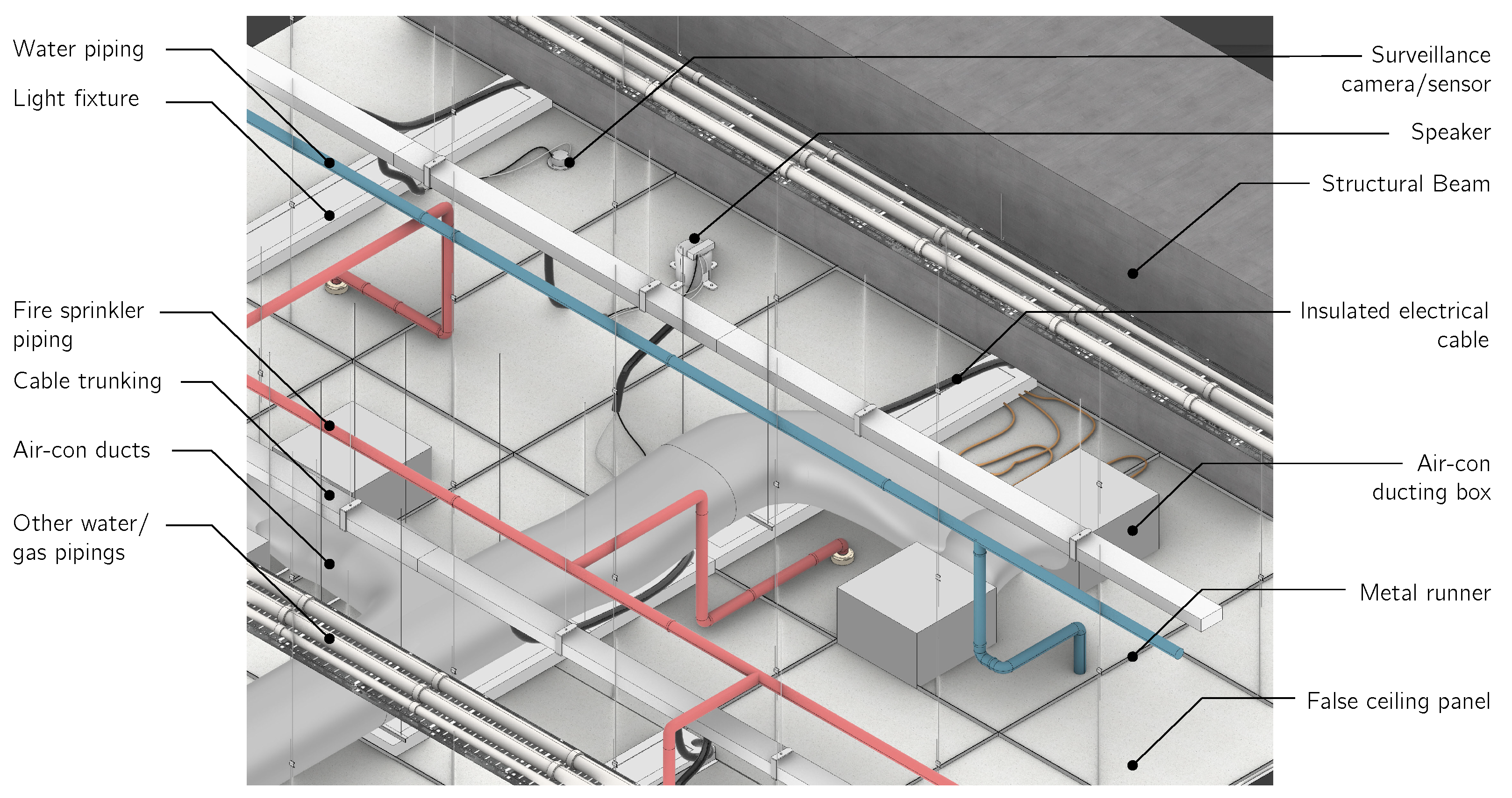
Mechanical, Electrical and Plumbing (MEP) services form an important backbone for buildings to equip their interior spaces with amenities such as air, water and electricity supply. The exposed ceiling ductwork, pipes and wires stemming from MEP components are sometimes unsightly and lack visual appeal [
1]. Beside MEP services, other installations in the false ceilings to support human activity for the space below often include speakers, wireless antennas or routers, close-circuit television (CCTV) security systems, smoke detectors, motion detectors, sprinklers among other amenities.
This paper refers to false ceiling standards such as the AS/NZS 2785 and BS EN 13964 [
32]. These building standards are commonly referenced and adopted in the construction industry, for the context and analysis of false ceilings. The scope of this paper will focus on the concealed grid system as it is commonly adopted in many buildings.
The suspended ceiling is a common type of false ceiling that is able to conceal these unattractive implements without affecting the performance of the MEP installations. As referenced from BS EN 13964 2014 Suspended Ceilings standards, suspended ceilings consist of a secondary ceiling that is dropped from the true ceiling, whilst being suspended from the structural slab above it. The secondary ceiling is made up of a structural grid known as a substructure [
33] to which either panel tiles or slats are either laid upon, clipped in or hooked onto. This structural grid is made up of inverted-T profile metal struts and runners that span the false ceiling area in a grid-like manner. The way the panels or slats are attached to the substructure and the resulting overall look of the false ceiling will determine the type of suspended ceiling, namely, a concealed grid, exposed grid or linear strip false ceiling. These panels or slats are made of different materials such as gypsum, polyvinyl chloride (PVC) fibre, metal, wood and so on, achieving various aesthetic objectives and functional performance. The typical components of a concealed grid false ceiling can be seen in
Figure 2.
3.1. Problems Observed within the False Ceiling Maintenance in Buildings
The false ceiling plenum is often overlooked until maintenance periods as it is usually hidden from human sight. MEP services that are housed within the plenum warrants for a significant amount of maintenance during the operational phase, which is also the longest phase within a building’s lifetime [
34]. This is more apparent for concealed suspended false ceilings where there is tendency of these problems being left undetected for extended periods of time. These problems can escalate in severity and incur large repair costs over time. Presence of unwanted pests and parasites typically stem from the presence of gaps and small crevices to the buildings’ exterior, as well as poor ventilation [
35]. Leakages from the ceiling could often be a result of problems involving the roofing or plumbing systems. Ignoring leaks over long periods can also lead to structural damage, mold, mildew growth and even discolouration or staining of adjacent surfaces. Besides Facility Management (FM) inspection works, examinations of the structural integrity of the building itself are often conducted regularly for the inspection of beams and columns that reside above the false ceiling.
In a present-day context, the means of access and the access points to the plenum varies depending on the type of false ceiling. For example, with concealed panel grid suspended ceiling systems, access panels or access hatches designating the entry points to the plenum are usually installed for maintenance works to be carried out. However, these access panels are not entirely void of risks and often require workers to be familiar with their operation. Care is required so as to not damage the panels caused by mishandling of the panels. As the design of the access panels vary with the type of ceiling system and the respective manufacturers, the operation of these panels are not standardized among buildings; some could be key-operated while others employ push-and-release mechanisms and so on. This lack of standardization in the construction aspect makes it difficult for proper comprehensive administration for maintenance.
Considering the overall area of ceiling space to be inspected, the removal of a single panel or tile is unlikely to grant a clear view of the entire space, as the scope of vision is obstructed by the complex array of infrastructural elements that reside within the space. Without the use of highly flexible and advanced endoscope equipment, multiple panels will need to be removed in sequence to carry out a comprehensive inspection of the space. Not only is the process cumbersome, as the maintenance worker would need to constantly move from one location to another, the process of dismounting and remounting the panels for comprehensive inspection also contributes to the general wear and tear of the false ceiling panels. In a report by the Association of Interior Specialists (AIS) in the UK, it stated that site visits conducted by AIS Advisory Service consultants discovered that ceilings are being damaged by untrained staff from the excessive removal of tiles to gain access to the service void above, and generated additional waste in the process [
36]. This then leads to additional unintended or unplanned costs for the overall maintenance process.
An obvious factor contributing to the above-mentioned problems in false ceiling maintenance is the fact that human workers experience restricted physical and visual access to the plenum. By expanding the range of access to the plenum, it can help improve present-day, cumbersome manual processes of both false ceiling and structural inspections.
3.2. Robotic Solutions for False Ceiling Inspection
In light of the current myriad of maintenance and inspection problems, the use of mobile robots is presented as a promising solution to complement or reduce the need for human labour in terms of inspection and maintenance [
37,
38]. Embedded with cameras, robots are able to perform regular inspections while minimising human intervention. Paired with different modes of locomotion such as wheeled, tracked or legged, robots are capable of performing tasks in the plenum which are difficult or dangerous to reach by humans. Advanced applications with in-built sensors are able to perform operations autonomously, allowing for regular inspection, further minimising human intervention. This would directly cut down occurrences of human occupational accidents, be it from working at heights, stray protruding false ceiling elements or human fatigue.
A study looking into robots from various works was done to compare and consider possible robot models for the inspection of false ceilings.
Table 1 includes a list of robots that are designed for confined spaces or wall surfaces. Robots such as [
39,
40] were designed to navigate on angled surfaces with possible applications in the inspection of walls. However, these robots were only proof-of-concept robots for wall navigation and were not yet equipped with any view capturing capabilities. On the other hand, robots such as [
41,
42] were specifically designed for the inspection of interior pipes, adopting mechanisms to navigate along the circular frame of pipes and ducts, which may not be optimal for deployment in the plenum.
The BIREM robot [
43] was designed to inspect the splicing parts of bridges, utilising magnetic wheels to adhere to structures of steel bridges. Its deployment is heavily dependent on its ability to adsorb onto steel surfaces through the use of wheels with attached magnets. This remains a challenge for BIREM deployments since these surfaces may not be widely available within the plenum zone of most buildings. The Blimp robot [
17] was used to inspect and capture images of the underside of a school gymnasium ceiling and a bridge deck structure by flying through an open volume. However, the deployment is more suitable for the inspection of structural elements for tall exposed ceilings rather than for components within the plenum.
Lastly, the robots presented in [
44] were designed for the inspection of ceiling elements in suspended ceilings, having been installed with strain gauges to assess the strain damage to structural elements caused by seismic forces. While the robots also had IR proximity sensors to aid in obstacle avoidance, the robots’ ability to overcome or navigate across obstacles present in a typical plenum setting was unclear.
While there are various robotic developments for inspection, the study of these works as shown in
Table 1 seem to reveal that, with the exception of [
44], the other robots were tested under ideal conditions, and are not suitable in their current state for inspection of concealed, suspended ceiling systems, as the robots were not designed to cater to the dimly lit and unstructured conditions for such sites. Furthermore, all the robots in
Table 1 are still in their conceptual design phases and have yet to consider the navigation requirements within the complex arrangement of structures, piping, electrical and mechanical components present in practical applications.
In comparison is a more recently developed solution built for actual suspended false ceiling site inspections—the Falcon robots. The Falcon robots, which are a new class of tracked inspection robots, are designed for false ceilings within buildings that comply with the AS/NZS 2785 and BS EN 13964 standards [
32]. In the Falcon robot class, the Falcon Mini and the Falcon Fetch is shown in
Figure 3 while its specifications are seen in
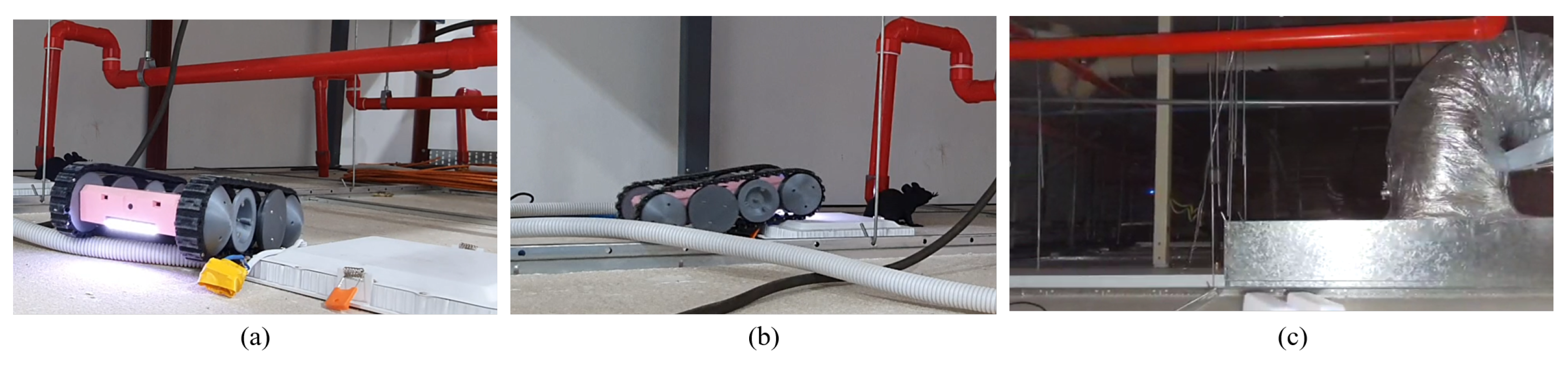
Table 2. Studies of deployments and testing of the Falcon Mini have been mentioned in [
45,
46] with the robots deployed for tasks such as the detection of rodent activity, as seen in
Figure 4.
4. Falcon Robots as Case Study
Two variants of the Falcon inspection robots, the Falcon Mini and the Falcon Fetch, along with their dimensions, are depicted in
Figure 3, respectively. These robots are developed to operate within the plenum of the suspended false ceiling [
45,
46]. While Falcon Mini is designed with a smaller build to navigate tight spaces, Falcon Fetch is built with additional tools such as a vacuum and a receptacle for basic cleaning works, and is also able to deploy rodenticide within the plenum to tackle the problem of rodent infestations. Overall, the robots’ lightweight and compact design allows the robot to maneuver within the confined space of a false ceiling.
Both the Falcon Fetch and Falcon Mini robots utilise a tracked drive mechanism, which would help the robots overcome the obstacles more effectively as compared to separate wheels or legged effectors [
46,
47,
48]. Wheeled and tracked mechanisms were utilised as they consist of fewer components as compared to legged or crawling modes of locomotion [
49]. They are also lower in cost due to the complexity involved in the control of legged locomotion [
30]. Thus, robots with wheel and tracked mechanisms would likely form the majority of the inspection robots in the plenum due to its economic viability.
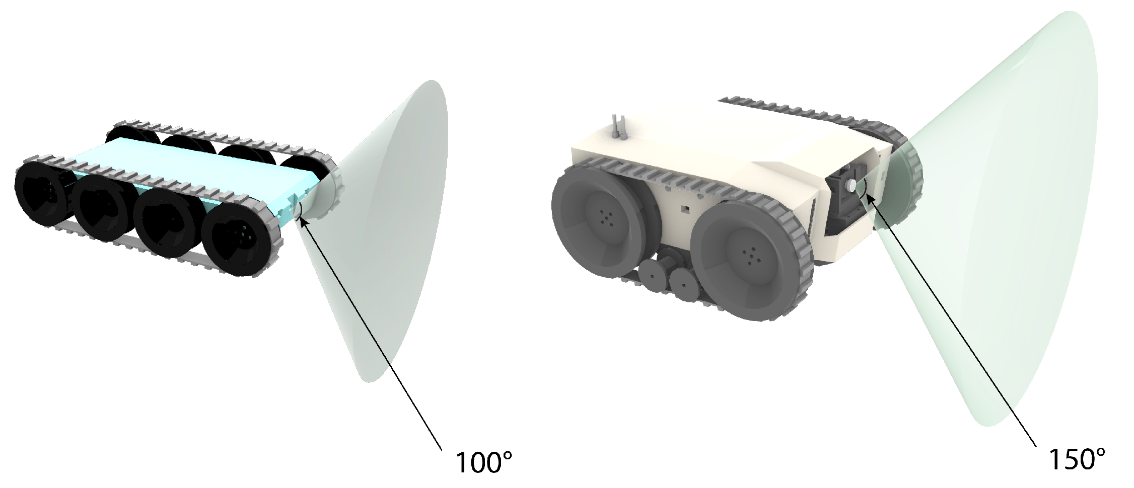
A front-facing camera is installed in both the Falcon Mini and Fetch to facilitate the inspection of defects and rodent activity. In order to facilitate inspection in the dark, the camera is paired with a light-emitting diode (LED) panel at the front of the robot to provide an illumination source. The field of view (FoV) for the Falcon robots can be seen in
Figure 5. The low-level working functionalities of the robot are handled with a local controller while the high-level processing functionalities such as vision processing are conducted in an external station. The robots thus require Wireless Fidelity (Wi-Fi) connection for both controlling and monitoring.
While it is recognised that the required spatial conditions vary depending on the robot platform used, considering the various inspection robots in
Table 1, the Falcon class of robots can be taken as a viable benchmark platform due to its functions and comparable dimensions that allow it to navigate stably within the unstructured plenum environment. This study recognises the relevance of the Falcon series in current, typical concealed grid suspended ceiling designs and aims to provide suitable guidelines to improve current and future robotic deployment efforts in false ceilings.
With the lack of regulations overseeing the organisation of concealed components during construction, the unstructured nature of false ceilings leads to barriers in robot perception and mobility. Since false ceiling designs and MEP layouts differ from one building to another, creating customised solutions for each application will be time-consuming and unscalable. Instead, a top-down approach that focuses on robot-inclusive spatial design can adapt the spatial environment to the needs of the robot (DfR) to easily address its productivity issues.
5. Derivation of Robot-Inclusive False Ceiling Guidelines
Robot-inclusive spatial design considers both robot and human ergonomics to determine ways to improve the design of surrounding objects and the areas of the robot’s workspace to optimize the robot’s performance [
50]. This approach brings together roboticists and architects to integrate the behaviour derived from the structure of spaces with that of the robot [
51]. Based on challenges posed by the human environment, roboticists typically seek to overcome the current limitations of the robot by improving on its functionality, such as robot perception, locomotion and platform design, human-robot interaction, and control [
52,
53]. Instead of increasing the complexity of the robot design by adopting highly customised solutions, such challenges could instead be addressed via improvements and changes in the spatial context to create robot-friendly environments.
In addition, as MEP systems are difficult to alter and modify after construction and implementation, it is important to raise such design concerns early [
54], for the parties involved to make necessary design amendments. By intervening in the design and construction stages of a building project, project owners would be able to avoid the need to adopt corrective measures to solve problems by employing preventive means after the building has been built. Having such guidelines on maintainability can also help to cut down the budget spent on maintenance, and improve service life of the building in the long run [
55].
To cater for a more conducive working environment for the robot [
24], a set of principles inspired by universal design guidelines are deduced to provide better framework and analysis. Five design principles were identified from universal design methods, namely: accessibility, safety, activity, observability and manipulability [
56,
57]. Accessibility delves into allocating sufficient provision of barrier-free access and travel for the robot to move to its required location to carry out its tasks. Safety involves cutting down the hazards that threaten to cause damage or physically stop the robot’s work. Activity explores how robots can be deployed alongside human labour seamlessly to minimise disruptions in the tasks for either group. Observability studies methods on how the robot can enhance its perception and visibility of the environment for navigation and operation. Manipulability deals with ways to upgrade the robot’s ability to act on or influence objects within its environment. The paper will place more emphasis on the activity, accessibility, safety and observability guidelines, which involves the robot’s access and view of the false ceiling space. These principles would help form a framework to guide the development of spatial design improvement strategies for effective robotic deployment.
As technology and robot developments advance over time, the suggested conditions for robot-inclusive false ceilings will also need to be updated. Robot-inclusive guidelines would thus be needed to tackle the problems faced by robotic deployments in the plenum to allow robots to function more productively and efficiently. The guidelines would thus be progressive in nature, but would account for existing technological conditions, which would mature over time as more capabilities would be added on as mentioned in [
46]. These guidelines are not exhaustive, and are to be updated as new false ceiling regulations, as well as inspection robot models, are refined over time.
5.1. Activity
The principle of activity for robot-inclusive environments aims to provide a catered workflow for both humans and robots. By streamlining and minimizing obstructions in the robot’s flow of work, greater efficiency and productivity of the robotic aid can be achieved for its work to complement human labour. Additionally, the robot-inclusive guidelines for activity aim to maximise the intersection of workspaces when the activities of both humans and robots match, and to minimize the overlap of workspaces when the tasks for the humans and robots differ greatly [
58]. In the case of the false ceiling, it is crucial to consider the method of robot deployment. Even though safety hazards posed to human inspection workers are alleviated with robotic aid, the deployment of the robot by the workers are still a manual and laborious process. Design guidelines under the activity principle that would assist in the inspection process for both the workers and the robots are proposed as follows as seen in
Table 3.
While achieving the above-mentioned points, design changes to false ceilings should be done without compromising its function and components. As these provisions and changes are subject to site conditions, it may be more difficult and costly to implement in existing buildings due to their age and difficulty in updating their current plenum layout. Instead, it would be preferable for some of the guidelines to be implemented in future false ceiling designs with consideration of robot deployments made during the phases prior to construction.
5.2. Accessibility
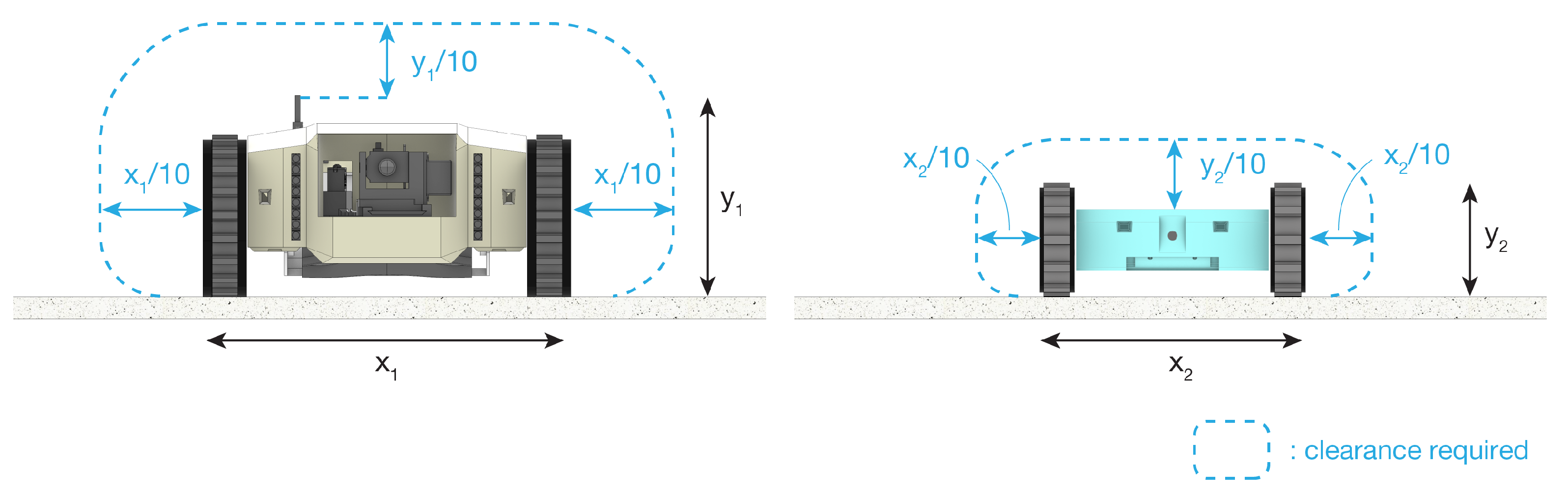
The lack of physical clearances within the false ceiling is one of the main hurdles for effective robotic deployment. To carry out comprehensive inspection of the site, the robot first needs to traverse to all necessary parts of the plenum to be in range to view the objects of interest and look out for defects. Since the robot’s movement is constrained to horizontal traversal on the base of the plenum, sufficient height and width clearances are required to maximise the robot’s accessible area. The physical clearances are dependent on the robot’s dimensions, its locomotion capabilities, and manipulator range if it possesses any. For an inspection robot, more emphasis is placed on the provision of clearance based on its physical dimensions and its field of view for optimal area coverage within the plenum. Guidelines that cater towards increasing the robot’s access in its spatial environment to improve its task efficiency would fall within this category.
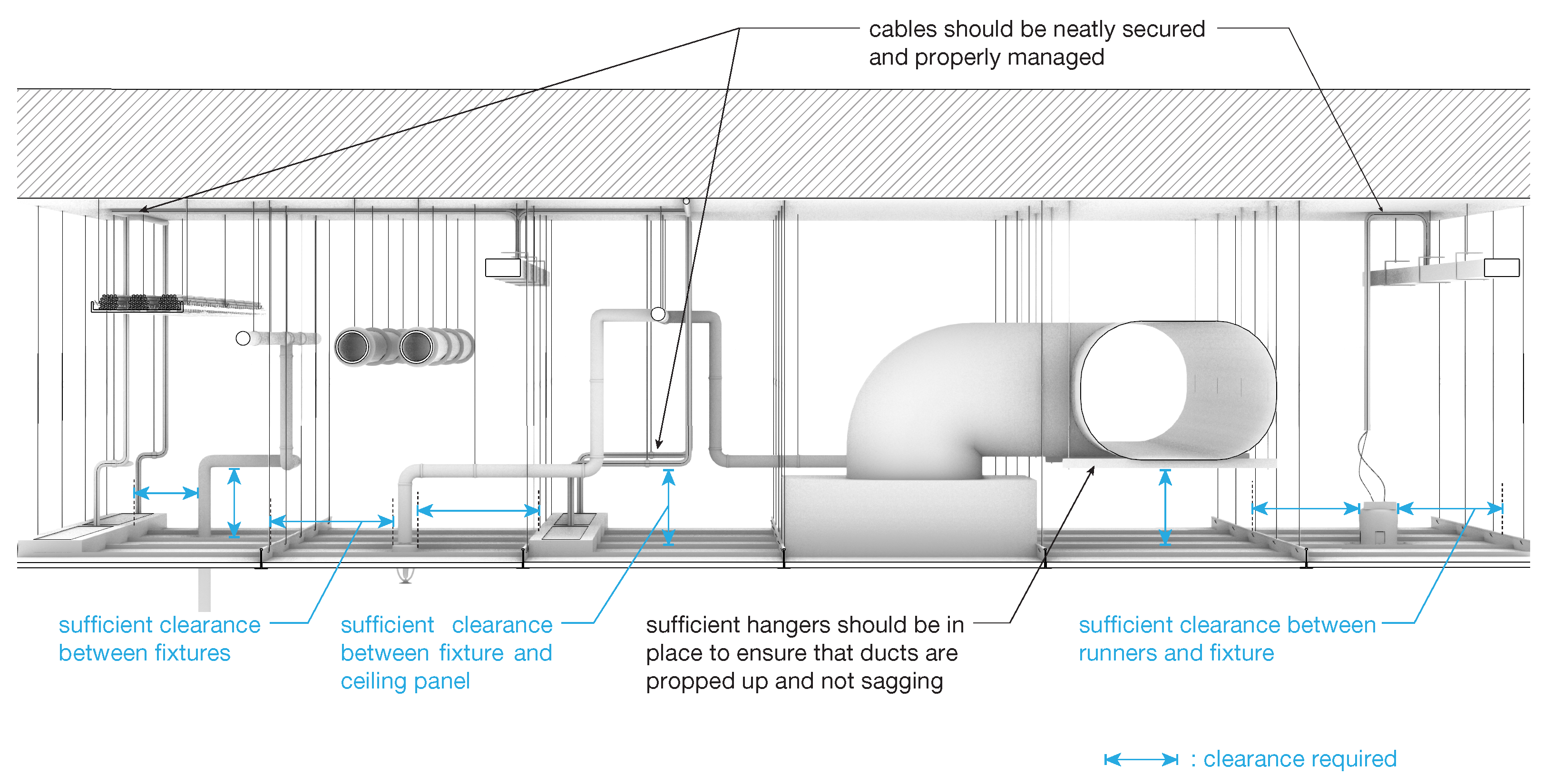
Figure 6 depicts the spatial clearances required for navigation for the case study of Falcon inspection robots. Based on typical operation conditions, the robot would require such clearances, otherwise it may hit other obstacles or face great difficulties navigating through them. These clearances also serve as a general rule which can be applied for the deployment of other suitable inspection robots.
Figure 7 illustrates the typical areas whereby clearances are required for the robot to bypass and navigate through, ensuring sufficient vertical and horizontal distances between components of the false ceiling and services within.
Design guidelines for inspection robots under the accessibility principle are thereby proposed in
Table 4, in their respective subsections:
5.2.1. Provision of Clearances for Robot’s Movement
It is important for services such as runners, fixtures and pipes to be positioned in an orderly and systemic fashion to cater for the robot’s movement and also meet the clearance requirements for human inspection and maintenance works. This can be achieved by determining the dimensions of the robot and accounting for the spatial requirements of the robot during its operation as it manoeuvres and overcomes obstacles within the plenum.
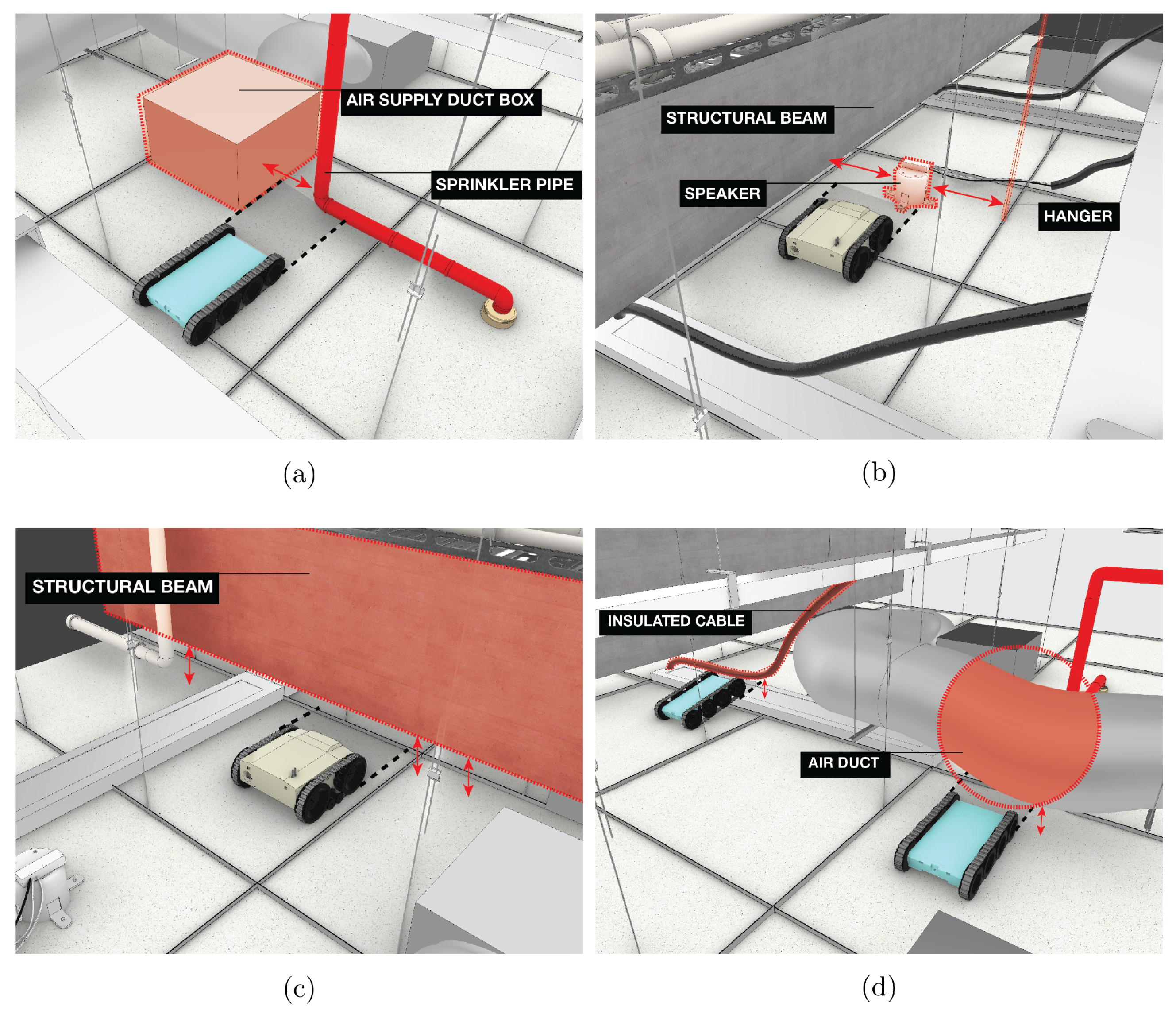
Figure 8 shows a few scenarios whereby inspection robots are unable to bypass obstacles within the false ceiling space due to insufficient spatial clearance between various components and structures.
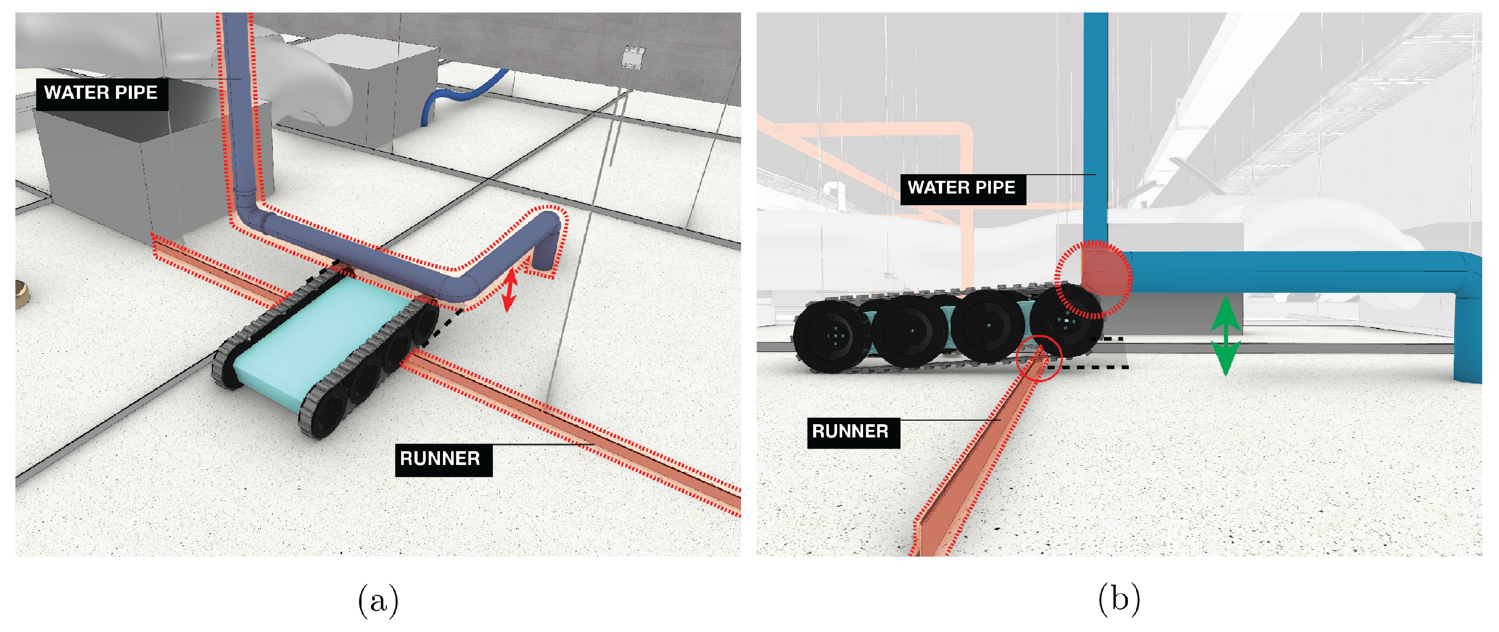
Figure 9 illustrates a scenario where despite having sufficient vertical clearance between the pipe and the ceiling panel, the robot’s movement is still obstructed as it has to first navigate over a runner. Hence, it is also important for clearances to take into account the robot’s movement across the plenum even as it overcomes obstacles.
5.2.2. Provision of Additional Access Points
Large fixed elements such as structural beams as shown in
Figure 8 that are located along the robot’s path may be present due to the structural requirement of the building. Such components are difficult to alter, and clearance provision for the robot under these circumstances may be impossible or involve heavy costs. Creating openings in structural elements for the robot’s traversal should only be considered if the structural integrity of the building will not be compromised [
59]. Instead, an alternative solution to this would be to introduce additional entry points to allow inspection robots to gain access to the necessary areas to achieve the required area coverage.
5.2.3. Ensure Sufficient Distance between Successive Obstacles in Close Proximity
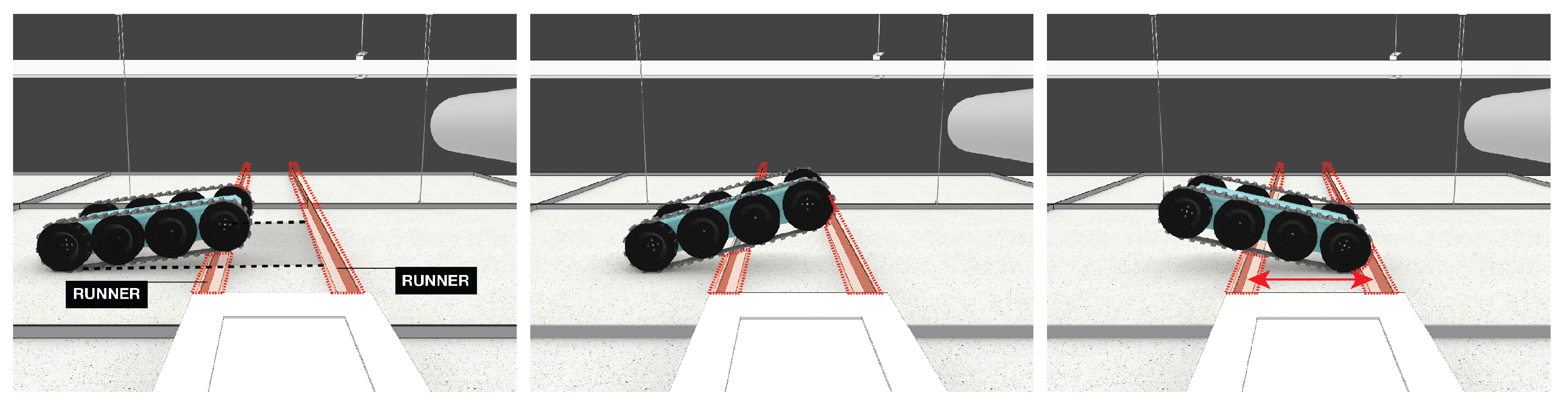
For ease of construction, structural elements such as runners are often laid out in a grid-like spacing. However, additional support structures may be required when installing fixtures onto the ceiling. Support structures that are placed too close to each other can pose as potential obstacles for the robot. This is illustrated in
Figure 10. Here, even though the robot is able to bypass the first runner without issue, it is unable to overcome the second runner due to the angle in which the robot approaches the second runner. As a result, the robot’s movement is halted and it is prevented from getting to the other side. Hence, sufficient spacing between runners or obstacles is to be given to allow the robot to travel across them, while ensuring that the necessary fixtures are well supported without obstructing the robot’s traversal. This is to cut down occurrences whereby the robot gets trapped due to insufficient clearance.
5.2.4. Adopt Suitable Structural Systems and Runner Profiles for the False Ceiling Substructure
Ceilings that require greater structural support for higher load-bearing purposes would call for a different structural makeup of the substructure, including the use of runner profiles of larger dimensions, or a combination of main runners, cross runners or other structural members.
Figure 11 illustrates a scenario where the robot is unable to overcome the runner due to its height. While the AS/NZS 2785 and BS EN 13964 standards do not necessarily specify dimensions for the runners used, the resulting height of exposed runners which the robots would need to overcome is heavily dependent on the actual construction and assembly of the substructure. The individual design of the runner is also subjected to the specifications by the manufacturers and suppliers.
Hence, it is important to ensure that the height threshold of obstacles is within the robot’s limits. In the case of the Falcon, which was designed to traverse over typical runners [
46], the maximum obstacle height it can overcome was recorded to be 55 mm [
45]. The cross-section profile of runners should be chosen considering the interface in which the robot would come in contact with the runner during its attempt to overcome it. On the other hand, understanding the interface might help inform robot designers on the type of locomotion that would be best suited to bypass the runners of the profile used for the substructure design.
5.3. Safety
The principle of safety looks to ensure that the robot is protected by minimising environmental hazards that would cause damage to the robot or render it immobile and cease its operation. Good organization of facilities during the construction phase, and proper maintenance during the corrective phase would preserve the cleanliness and orderliness of the plenum space. Other general guidelines for spatial design that prolong the robot’s condition and shelf life by keeping it safe during operation and storage would fall under this category.
Figure 12,
Figure 13 and
Figure 14 illustrate a few scenarios where the robot may encounter haphazard environmental elements that are difficult to detect and would cause damage to the inspection robot.
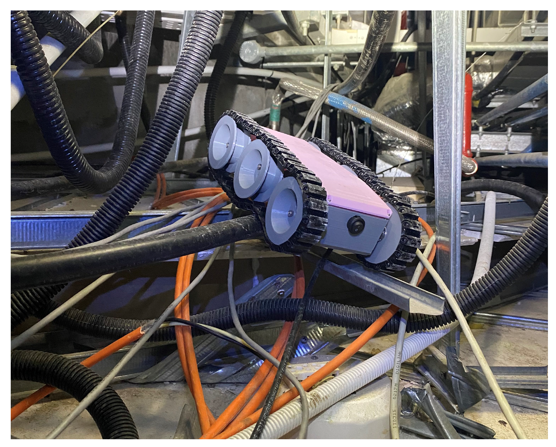
As the plenum is typically kept hidden, there is a tendency for poor cable and wire management to occur. These also become potential obstacles and safety hazards, as it is difficult to navigate through a messy assembly of cables. Such poor practices may not necessarily be limited to just cables or wires, but also to the haphazard placement of excess runner parts or exposed nails. As illustrated in
Figure 12, the inspection robot is seen navigating through a mess of loosely managed components consisting of cables, wires, metal runners and pipes. Such scenarios are definitely not ideal for the safety of the robot as the components can easily interfere with the robot’s locomotion. Typically, the more moving parts the locomotion system uses, the easier it is for the robot to get caught in loose components in the false ceiling environment.
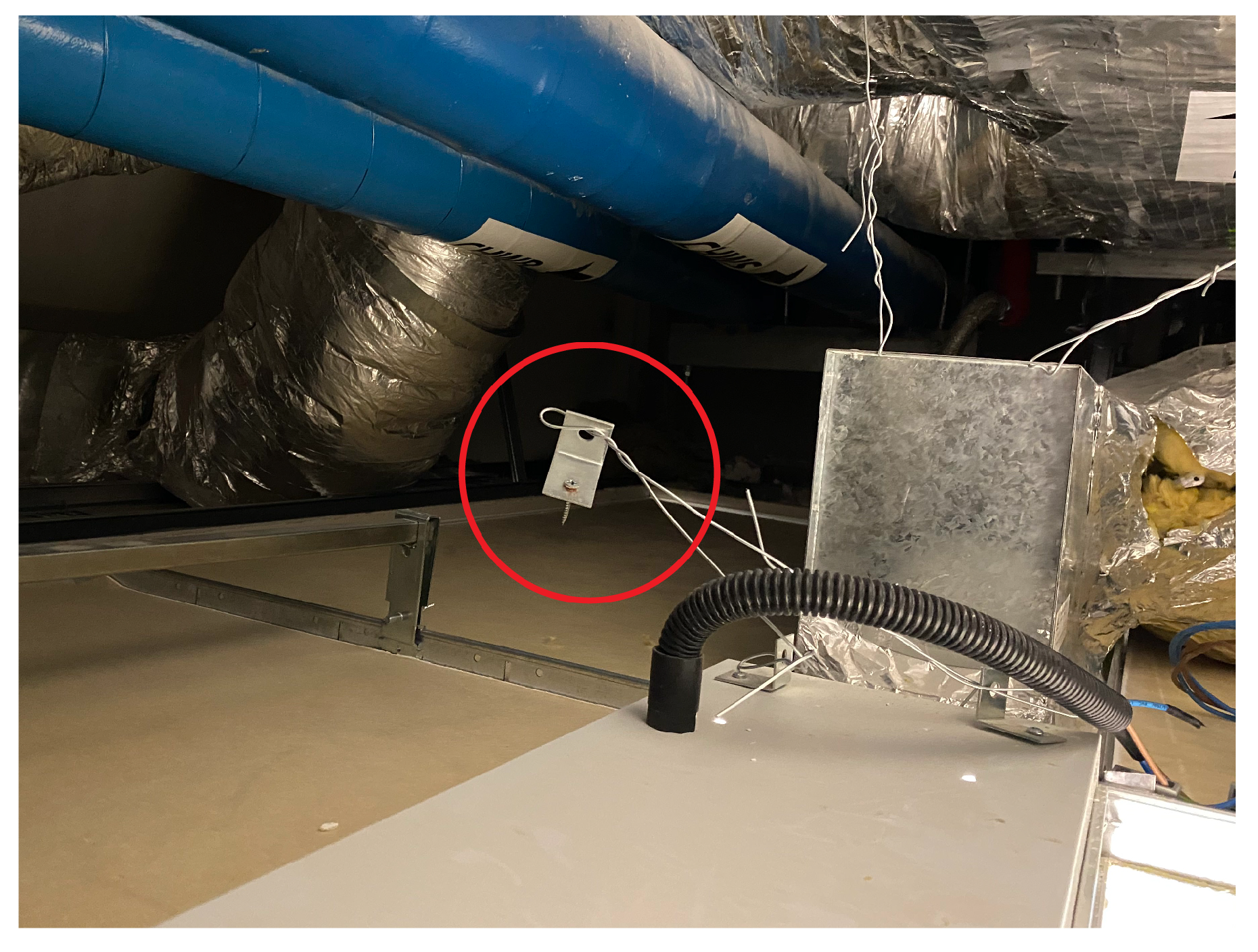
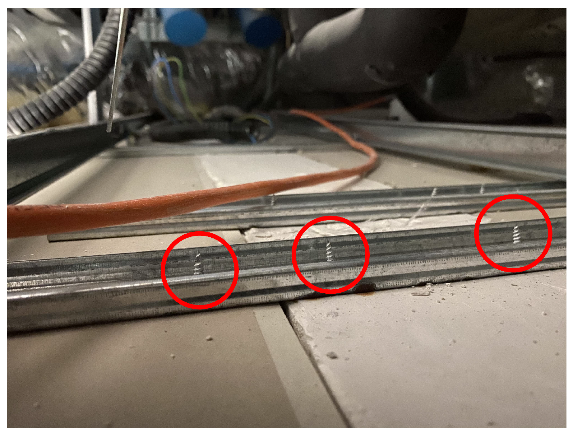
In
Figure 13, we observe an exposed L-bracket and nail along the possible pathway of the robot. Even if the robot is able to manoeuvre through it, running the robot through such exposed sharp elements would likely cause damage to the robot. Similarly in
Figure 14, exposed nails that are not carefully stowed away properly become dangerous obstacles along a robot’s path as they can easily damage the robot treads if the robot runs over them.
Even though the false ceiling inspection robot is designed to be lightweight to cause minimal damage to the elements of the false ceiling by its bulk, it would still add transient load to the structure during movement. Any existing damaged parts of the false ceiling such as small cracks or holes can worsen as the robot moves on them over time, and cause panel structural failure in the worst case scenario. As with all robotic deployments, it is important that other non-maintenance personnel sharing the same space should be made aware of the deployment of robot during operation, in case of false ceiling panel structural failure after prolonged wear and tear and repeated robot movement on the panel over multiple maintenance cycles.
In view of the aforementioned problems, some guidelines under the safety principle are proposed as seen in
Table 5.
Facilities dealing with liquids or flammable substances should be preferably separated from the other amenities to limit damage caused by leakages or fires. Proper planning of HVAC ducting should be executed in order to cut down on excessive ducting which could slump without proper support and cause access or observation issues for the robot during the inspection process.
5.4. Observability
The robot-inclusive principles categorised under observability consider modifications to the spatial environment to allow the robot to view its surroundings during operation, and perform its tasks with minimal visual obstructions. The ability to clearly view all objects of interest is crucial to the work of the inspection robot. One main issue in hindering the robot’s inspection process is the presence of large fixtures or components in the plenum that reduce or block the field of view of the robot. Furthermore, the lighting conditions within the plenum and the materiality of the fixtures within the false ceiling may also adversely affect the perception of the robot.
Camera systems installed on the inspection robots have to take into account cost and weight restrictions. A camera with higher specifications and more sensors would naturally result in a heavier platform, as well as complexity in data processing, which may not be most suitable for such applications. With these considerations, the Falcon Mini was built with a front WiFi camera of 640 × 480 pixel resolution with a 100
field of view, with planned future upgrades to the camera to a higher resolution with a larger field of view. The current camera quality of the Falcon Mini is similar to the Blimp robot in [
17], whereas a wireless camera with 350,000 pixel resolution was installed on both the robots presented in [
44]. The Falcon Fetch has a 960 × 480 pixel camera with a 150
field of view. As such, the guidelines should also take note of the visual capabilities of available robotic solutions for future designs of false ceilings. Adopting these guidelines would allow for the collection of clearer images and information from its visual cameras, which would help to facilitate any follow-up steps required for correction.
Table 6 shows the principles and sections detailing the guidelines in the following subsections.
5.4.1. Hierarchical Positioning of MEP Components
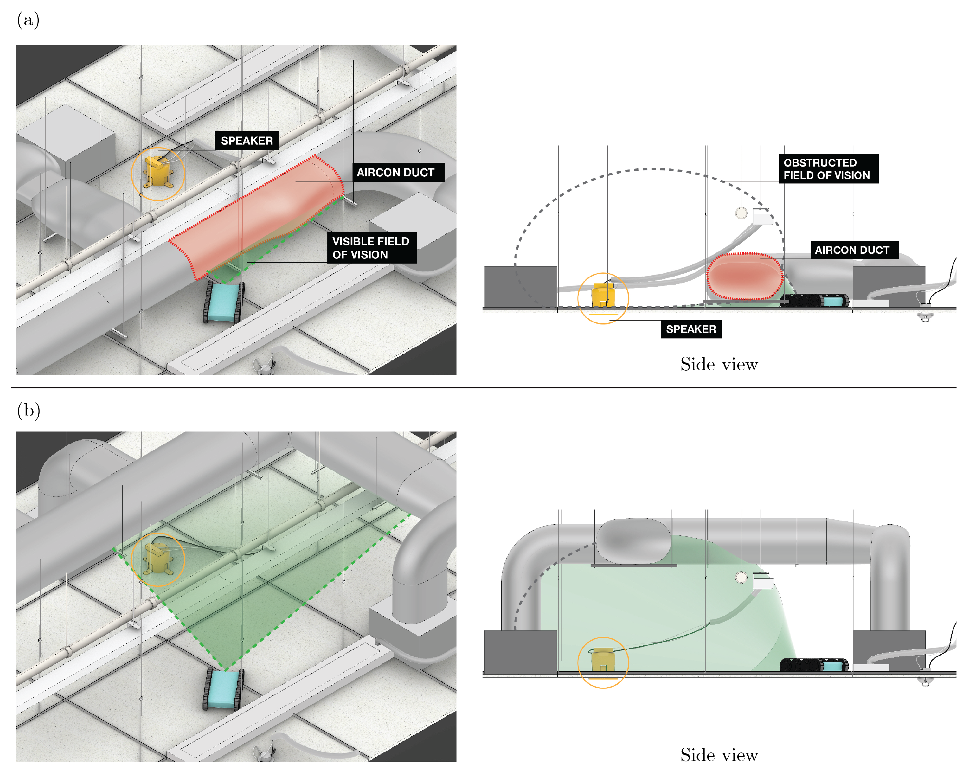
By reordering the position of MEP services and components within the plenum, a greater effective field of vision for the robot can be achieved by reducing visual obstructions. As such, a hierarchy of tiers for the placement of facilities is proposed based on the typical dimensions of false ceiling components, starting from the lowest level of the plenum to the uppermost level. An illustration is shown in
Figure 15, showing a comparison before and after reordering HVAC ducting.
- 1.
Items with small cross-sectional footprint (e.g., wires/thin cables)
- 2.
Water pipes, smaller gas pipes, on-surface piping
- 3.
Large cables, cable trays, bus way, large gas pipes
- 4.
Air-conditioning (aircon) ducts
- 5.
Large structural elements
Moreover, it is important to note that for safety concerns, electrical pipes and telecommunication pipes should be installed above water pipes [
60].
5.4.2. Easy Identification of MEP Components
Besides adopting good MEP identification labelling practice, such as adhering to ANSI/TIA-606 or ASME A13.1 standards, capturing images with high contrast would further help with identification [
61] and defect detection [
62]. In addition, there have been forays into utilising radio frequency identification (RFID) tags into MEP systems for easier identification of components within a building project [
63]. This reference system could also be modified and implemented in existing false ceilings to allow inspection robots to better identify individual components of interest and help with its localisation within the plenum.
5.4.3. Material Selection
The surfaces of the amenities such as the piping, cables or runners used in the false ceiling should not be overly reflective, so as to reduce glare or light flares during inspection. This is especially so if the robot utilises point light sources for illumination or if the light source is located near to the robot’s camera itself. Moreover, defects on reflective surfaces become only detectable from a particular direction from the angle of illumination [
64]. Using matte surfaces for the amenities, as well as an ambient or diffuse light source, would help improve surface defect detection.
6. Conclusions
This paper has highlighted the need for regular inspection for false ceilings, specifically in the case of concealed suspended grid false ceilings. The current limitations and risks of the maintenance process encountered by human workers include physical and visual restrictions to the false ceiling space. Robotic solutions, out of other automated solutions such as IoT based techniques, have been deduced to greatly assist in mitigating such issues. False ceiling inspection robots can assist in frequent inspections while maintaining disruptions to the existing structures and fixtures. Due the complex and unstructured nature of existing false ceiling site conditions, robot-inclusive guidelines were proposed to improve the design of the false ceilings in order to increase the productivity and efficiency of robot deployments. These robot-inclusive design guidelines were derived based on a set of design principles, as well as observations from the Falcon, a class of false ceiling inspection robots developed by Oceania Robotics. The guidelines were proposed for a generic class of false ceiling inspection robots, and vary depending on the type and layout of false ceilings. As new designs of false ceilings and robots advances, these guidelines could be further refined and updated to improve the productivity of robotic false ceiling inspection. For future work, close coordination with MEP engineers, architects and contractors would be required for a holistic understanding of the impact of the robot on the structure of the false ceiling.


 ,
, 


