1. Introduction
Ordinary structures exposed to strong earthquake ground motions are expected to undergo significant inelastic deformations. On the other hand, conventional seismic design methods use elastic procedures where earthquake ground motions are represented by equivalent static forces. The safety of the structures that are designed using elastic procedures but are expected to undergo significant inelastic deformations are ensured through prescriptive measures. However, their real behavior is never assessed. Performance-based-design procedures aim to provide a more realistic approach by incorporating the assessment of the structure under different seismic hazard levels in the design process. Majority of these efforts, so far, are based on assessment of the structure using maximum deformation demands. Although maximum deformation demand provides a much better parameter to assess the expected performance than elastic force demands, it fails to explicitly capture the accumulation of damage through inelastic deformations likely to occur prior to and after the maximum deformation. On the other hand, energy-based design inherently considers the cumulative effects of repetitive inelastic deformations that occur in ordinary structures under severe earthquakes.
Energy-based design, as first suggested by Housner [
1] is based on the principle that the energy dissipation capacity provided to a structure should be greater than the energy demand imposed by a design earthquake [
2]. To this end, reliable estimation of energy demands is a key component of the energy-based design procedure. Therefore, several researchers have studied the energy demands imposed on structures by earthquake ground motions. Fajfar and Vidic [
3] developed approximate equations based on non-dimensional parameters to develop inelastic design spectra for hysteretic and input energy. Uang and Bertero [
4] evaluated the physical meaning of absolute and relative input energy for single-degree-of-freedom (SDOF) systems and also developed inelastic input energy spectra. Chapman [
5] assessed the use of elastic input energy for seismic hazard analysis and concluded that it offers a potential advantage over the elastic response spectrum as it considers the ground motion duration. Bruneau and Wang [
6] explored the energy demands of single-degree-of-freedom systems and stated that if the hysteretic energy is of interest, both the absolute and the relative energy methods can be used although the latter has closer relationship to the parameters of engineering interest [
7]. They have also indicated that small amounts of damping energy can lead to significant reduction in the amount of hysteretic energy dissipated by a structure. In addition, Bruneau and Wang [
7] have proposed simplified methods for computing normalized energy demands by converting the ground motion accelerograms to equivalent pulses. Several other researchers have developed energy demand spectra, both hysteretic and input, based on numerical and statistical studies conducted on single-degree-of-freedom systems [
8,
9,
10,
11,
12,
13]. The biggest advantage of the studies conducted using SDOF systems is the possibility to evaluate the behavior of a vast number of structural configurations (i.e., structures with different fundamental periods and inelasticity levels) under a large ground motion record set. Therefore, these studies provide very valuable information on total energy demands in structures subjected to earthquakes. On the other hand, they fail to address how the energy demands flow in a MDOF systems, where the behavior of the system is affected by more parameters than simply the fundamental period or the inelasticity level of the system.
Although several studies have focused on developing an understanding of the total energy demands in SDOF systems, few have focused on multi-degree-of-freedom (MDOF) systems. For a MDOF system, the distribution of hysteretic energy demands among different components of the structure is, arguably, as important as the total energy demand since each structural component needs to be designed to satisfy the hysteretic energy demand on that component. This distribution can be significantly influenced by several factors such as the relative strength of the components and modeling assumptions used in the analysis. Shen and Akbaş [
14] investigated the energy demands in steel moment-resisting frames ranging from three to ten stories. As a result of nonlinear time history analyses conducted under six ground motions, they have concluded that the energy distribution in a structure is insensitive both to the ground motion record and to the intensity of the ground motion. This study also pointed out that the energy concept based on SDOF systems has significant limitations when extended to MDOF systems. Chou and Uang [
15] developed a procedure to compute the absorbed energy in a multistory frame from energy spectra based on static pushover analysis for the first two modes of the structure. Although the developed procedure has been shown to be effective in estimating energy demands in frame structures, the study has been limited to three ground motions and, arguably, cannot capture potential ground motion to ground motion variability of hysteretic energy demands satisfactorily. Ghosh and Collins [
16] developed a nonlinear static analysis-based method that uses an inelastic equivalent single-degree-of-freedom model to estimate the hysteretic energy demands in MDOF systems. Later Prasanth et al. [
17] further developed this methodology to include several modes by using modal pushover analysis. However, both articles focused on the estimation of the total hysteretic energy demands and not on the hysteretic energy distribution among the components of MDOF systems. More recently, Ucar [
18] has developed an equation for computing the input energy demands in MDOF systems in terms of the input energy demands in
nth-mode SDOF system. The study concluded that although a structure exhibits different input energy responses when subjected to different ground motion records, different structures with similar fundamental periods show very similar response to the same ground motion. Furthermore, Ucar [
18] concluded that linear input energies of MDOF systems can be estimated using equivalent SDOF systems. However, the study focused mainly on the elastic input energy and the hysteretic energy response of inelastic MDOF systems has not been addressed.
This study aims to build on the knowledge obtained from earlier studies on single- and multi-degree-of-freedom systems in providing an insight into hysteretic energy demands of MDOF systems and the distribution of these demands among different components. This is achieved through nonlinear response history analyses (RHA) of three-, nine-, and twenty-story moment-resisting frames conducted under 40 ground motion records scaled to represent three different hazard levels. Nonlinear response history analyses were repeated for SDOF systems to evaluate the effectiveness of the SDOF approach in estimating the total input and hysteretic energy demands in MDOF systems. In addition, the sensitivity of the hysteretic energy distribution in a MDOF system to relative strength of adjoining components and to the damping model used in the analysis has been investigated.
2. Energy Equations for Single-Degree-of-Freedom Systems
The equation of motion for a single-degree-of-freedom system subjected to a ground acceleration can be written as:
where
u is the relative displacement of mass
m with respect to the base of the SDOF,
is the natural circular frequency of the undamped system,
is the damping factor as a fraction of the critical damping and
is the restoring force. Integrating Equation (
1) with respect to the relative displacement
u leads to the relative energy equation:
The terms in Equation (
2) represent, respectively, the kinetic energy per mass,
, the damping energy per mass
, the absorbed energy per mass,
, and the input energy per mass,
. The absorbed energy per unit mass is composed of recoverable strain energy,
, and irrecoverable hysteretic energy,
.
Using
and
, the kinetic energy and the damping energy per unit mass can respectively be computed as:
The recoverable strain energy,
, can be computed as:
Finally, the input energy per unit mass is:
For systems that start from a resting position and come to the same resting position at the end of the motion, the total kinetic energy,
, and the strain energy,
, become zero when the system comes to a rest [
12,
19].
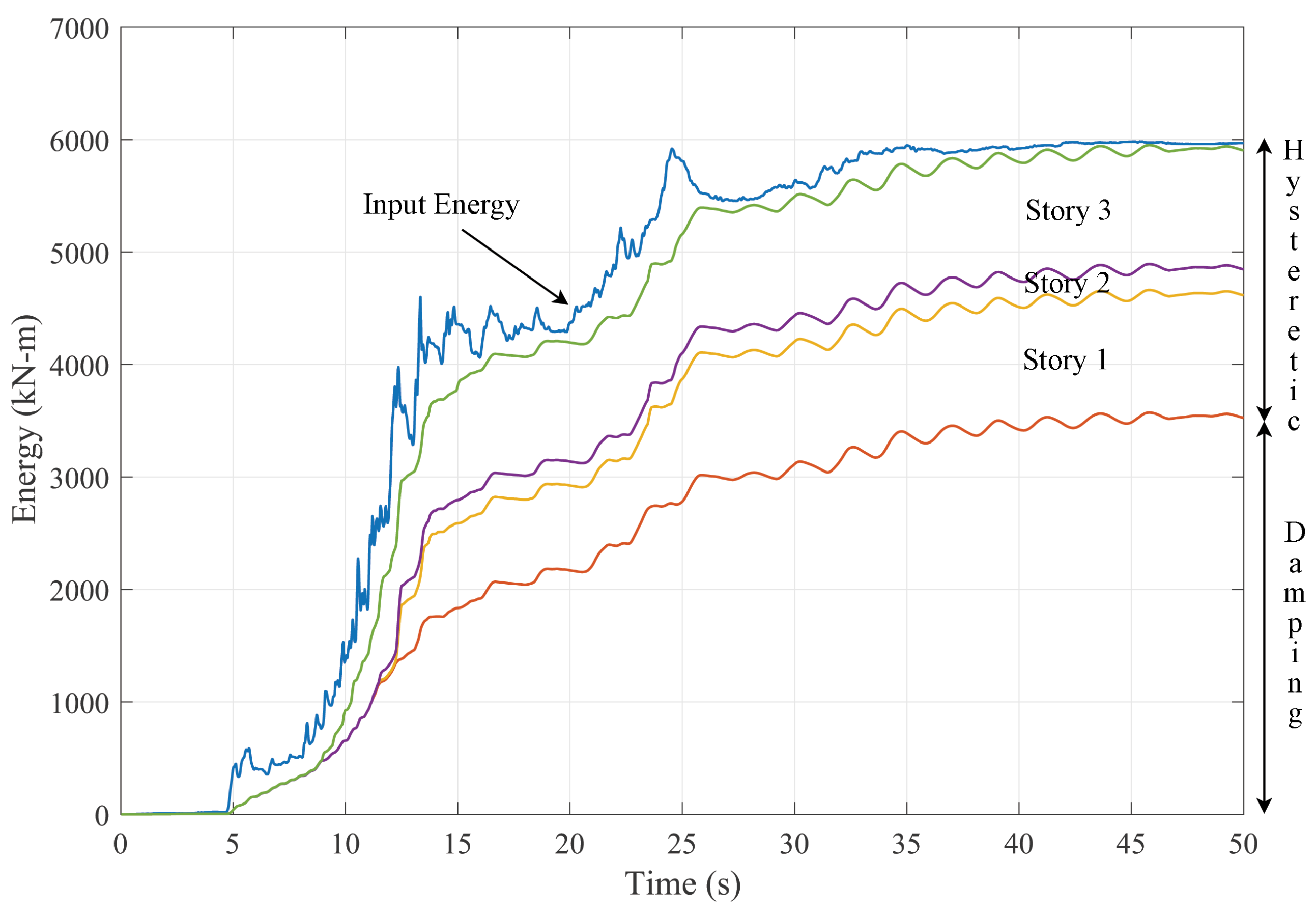
Thus, at the end of the motion, the relative energy equation can be written as . In other words, the total input energy imposed on the structure by an earthquake is dissipated by two mechanisms: damping and hysteretic energy. Of these two mechanisms, hysteretic energy demand is the most interesting to the engineers as the performance of a structure under an earthquake is determined by the relationship between the hysteretic energy absorption capacity of the structure and the hysteretic energy demand. This is because, the hysteretic energy has a one-to-one correspondence with inelastic deformations that occur in a structure during an earthquake. This correspondence is not limited to the singular value of the maximum inelastic deformation but encompasses each incremental inelastic deformation. Hence, the hysteretic energy demand is very strongly correlated with structural damage as it takes into account the cumulative effects of repetitive inelastic deformations. Therefore, hysteretic energy demands in both single- and multi-degree-of-freedom structures will be the main focus of this article.
It should also be noted that although the energy demand computations have been summarized only for relative energy, hysteretic energy and damping energy demands will remain the same if the computation is carried out using absolute energy terms as the only difference between these two formulations is in the kinetic energy formulation, which vanishes at the end of the ground motion [
4].
3. Energy Equation for Multi-Degree-of-Freedom Systems
Similar to SDOF systems, the total input energy for a MDOF system under an earthquake ground motion is equal to the sum of kinetic, damping, elastic strain and hysteretic energies. As stated earlier, kinetic energy and elastic strain energy that vanish once the structure comes back to the resting position are not the focus of this study and their derivation for MDOF systems will be skipped for the sake of brevity. For readers who are interested in the computation of these terms, Uang and Bertero [
4] provide an excellent summary.
For an N-degree of freedom system, the relative input energy,
can be computed as:
where
is the mass of the
ith floor,
and
are the relative displacement and velocity vectors, respectively.
Similarly, the damping energy can be computed as:
where
is the viscous damping matrix and
is the damping force vector for each story;
.
Finally, the hysteretic energy dissipated by each element, i, is equal to the area under the moment-plastic rotation curve. The cumulative hysteretic energy dissipated by the entire system can then be computed as the sum of hysteretic energy dissipated by all the elements in the system.
For a MDOF system that comes to rest after the ground motion is over, the sum of the damping energy and the cumulative hysteretic energy converges to the input energy as the system comes to a rest.
Figure 1 presents the development of input, damping and hysteretic energy of a three-story MDOF with time for a sample ground motion.
4. Modeling Assumptions for the Analyzed Systems and Selection of Ground Motions
Linear and nonlinear response history analyses were conducted on both SDOF and MDOF systems. An elastic-perfectly-plastic oscillator with a constant initial stiffness has been used for the nonlinear response history analyses of SDOF systems. The mass of the oscillator has been adjusted to vary the elastic period while the yield capacity of the oscillator has been modified to achieve the desired strength reduction factor,
R, where
;
m is the mass of the oscillator,
is the ordinate of the elastic acceleration response spectrum and
is the yield strength of the elastic-perfectly-plastic oscillator. The energy demand of an oscillator is very likely to be affected by the structural model of the oscillator, especially for systems with strength and stiffness degradation. The effects of the structural model on the energy demands of an oscillator has been studied extensively [
8] and goes beyond the scope of this study.
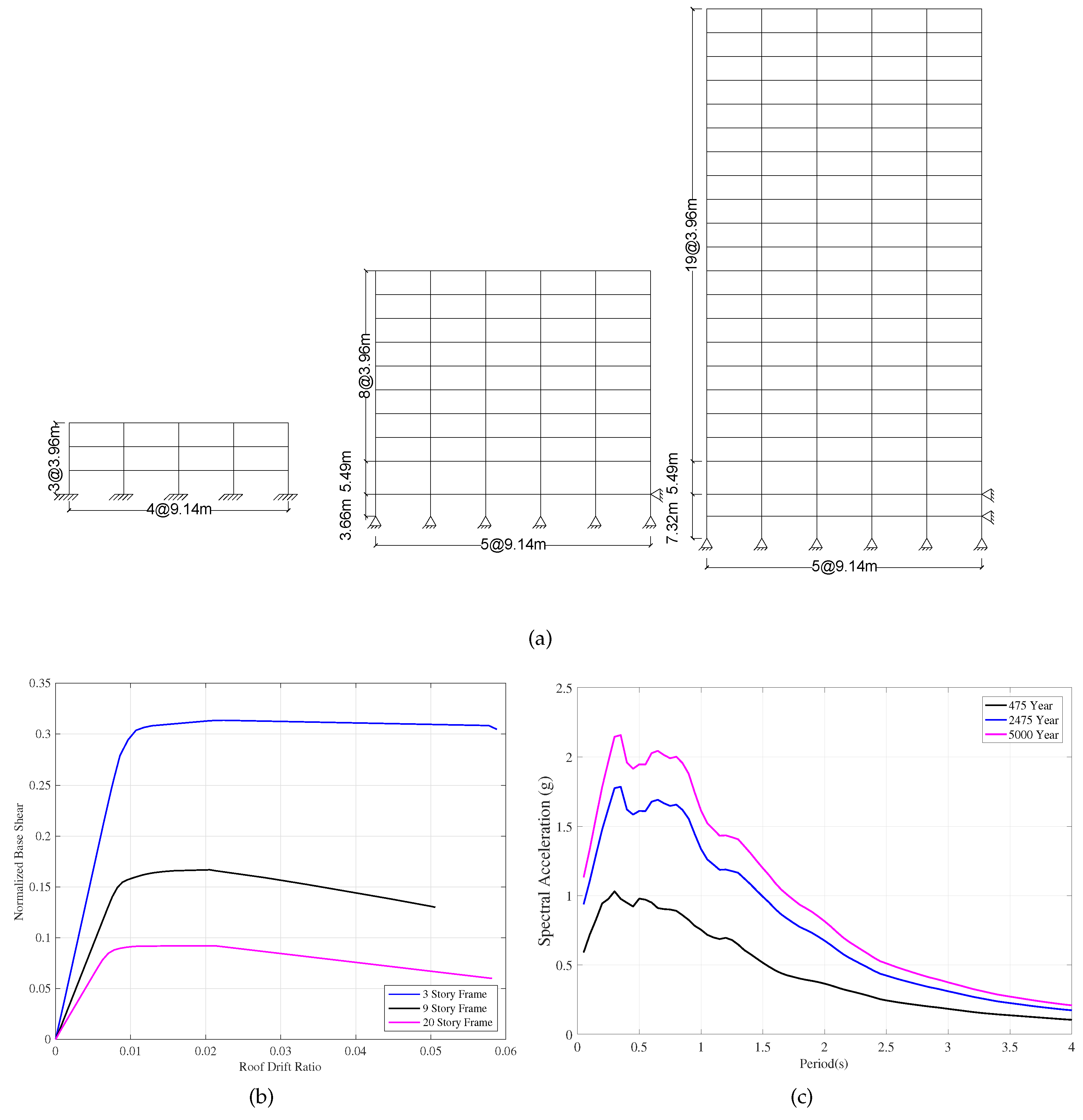
Three-, nine- and twenty-story steel moment-resisting frames designed for Los Angeles within SAC project [
20] is used to evaluate the input and hysteretic energy demands in MDOF systems.
Figure 2a shows the elevation view of the buildings. The frames were chosen to cover a wide range of vibration periods as well has higher mode contributions. The periods and the modal mass percentage of the first three modes of each frame computed from elastic eigen-value analysis is summarized in
Table 1. Although the modal mass percentage of the first modes of the nine- and twenty-story buildings are relatively high, the behavior of these structures has been documented [
21] to be affected significantly by higher modes. The geometrical properties of the frames are omitted for brevity but detailed descriptions of the structures are available in [
20].
Detailed two-dimensional (2D) models of one of the peripheral frames of each of the buildings are developed in the
OpenSees computational environment. Columns and beams are modeled using force-based beam-column elements that combine finite length “plastic hinge” regions at the element ends with an interior elastic region [
22]. Inelasticity in beam and column cross-sections are modeled using stress-resultant, elastic-perfectly plastic moment-curvature relations. Assigned member capacities reflected the expected yield strength of structural steel; 339 MPa. P-delta effects are considered in all the analyses. Fictitious beams and columns are used at each floor to be able to consider the contribution of the gravity (internal) frames of the structures to the P-delta effects.
As in the case of SDOF systems, the approach used in the modeling of the nonlinear behavior of elements is very likely to significantly influence the energy demands of MDOF systems. The modeling parameters that are likely to have a significant influence on the energy demands include but not limited to the modeling of the behavior of joints, strength and stiffness degradation in the material model, the length of the plastic hinge zone and the number of integration points. The effects of these modeling parameters on the energy demands is a crucial issue that needs to be investigated thoroughly. However, this goes beyond the scope of this study, which aims to provide, for the first time, a detailed insight into the distribution of energy demands on MDOF systems.
The capacity curves of the buildings obtained from a nonlinear static (pushover) analysis under an invariant first mode load pattern is depicted in
Figure 2b.
Two sets of ground motions that are representative of different hazard levels are used in the nonlinear response history analysis. Each set consists of 20 recorded and simulated ground motions that represent return periods of 475 years (10% probability of exceedance (PE) in 50 years; referred to as 10/50 set) and 2475 years (2% PE in 50 years; referred to as 2/50 set). All ground motions were recorded on stiff soil with shear wave velocity,
to 360 m/s. This is in consistence with the assumed site conditions in the design process of the SAC buildings [
20]. Ten ground motions for each set were taken from the SAC steel research project. Detailed information on the SAC ground motions is given in FEMA 355C report [
20]. These ground motions were supplemented by ten recorded ground motions that have been previously assembled for a structure located in Los Angeles. The ground motions used in the analysis were selected using the procedure summarized in [
23]. First, a hazard curve was defined that quantifies ground motion intensity versus frequency of occurrence. Individual points along the hazard curve represent various earthquake scenarios ranging from frequent to very rare events. For three distinct events (50% probability of exceedance (PE) in 50 years, 10% PE in 50 years, and 2% PE in 50 years), target spectra were generated and ground motions were selected using the USGS seismic disaggregation data from the PEER NGA database [
24] and amplitude scaled to best match the target spectra. Details of the selection process of these ground motions can be found in [
25]. Information about the ground motions used in the analyses is provided in
Table 2.
The ground motion set selected for 2/50 event is then scaled to represent ground motions with a return period of 5000 years (1% PE in 50 years; referred to as 1/50 set). The ground motions are scaled such that on average, their spectral values match with a least square error fit to the target hazard curves within a period range of 0.1 and 4.0 s.
Figure 2c depicts the median response spectra for the selected ground motions for each hazard level.
5. Energy Demands in Single-Degree-of-Freedom Systems
Linear and nonlinear response history analyses were conducted on SDOF systems for the 10/50 and 2/50 ground motion sets to develop input and hysteretic energy demand spectra. The analyses were conducted for a period range between 0.05 s and 4.0 s and for systems with a constant strength reduction factor of and 8.
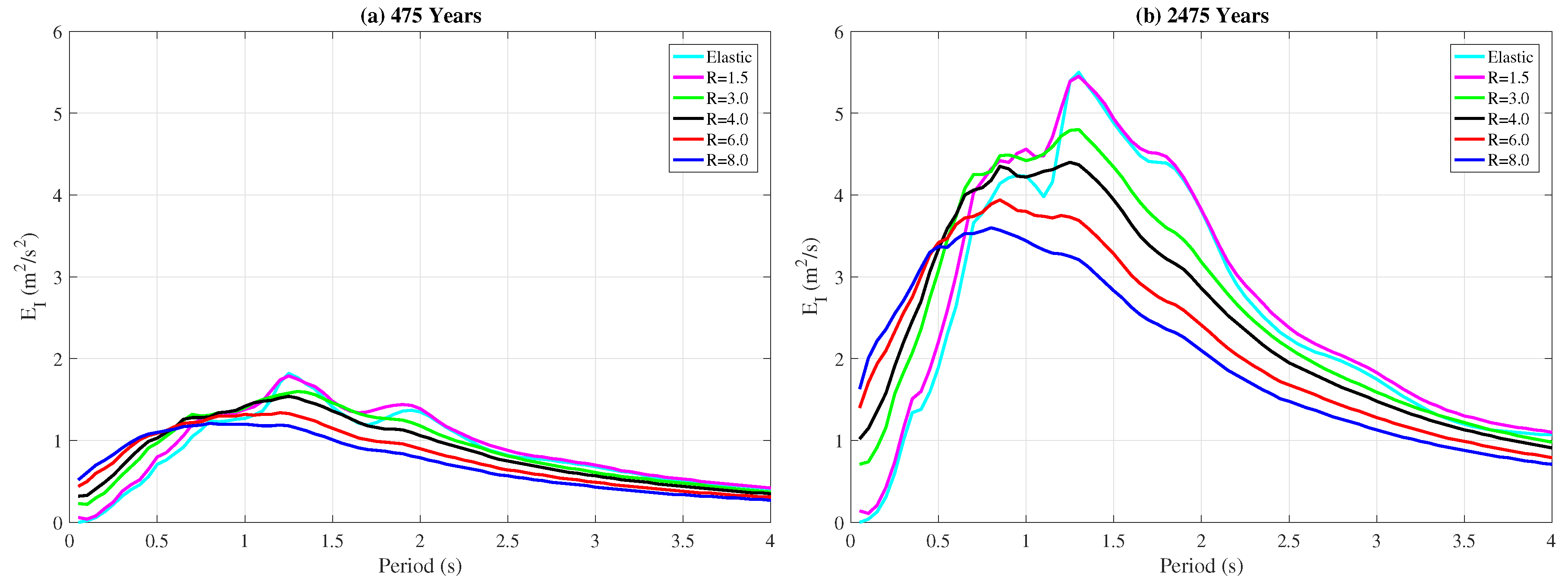
Input energy per unit mass spectra,
, plotted in
Figure 3 show that the median input energy demand decreases with increased inelasticity for the structures in the constant velocity and constant displacement regions of the spectrum for both 475- and 2475-year events. This trend reverses at around
s and, for the constant acceleration region, the input energy demand increases with increasing inelasticity. This observation is in line with other studies and suggests that the input energy demands computed for elastic single-degree-of-freedom systems provides reliable, if not conservative, estimates for their inelastic counterparts with periods greater than 0.5 s. This observation further suggests that the attenuation models developed for elastic energy demands, e.g., [
8,
9], can be used to estimate the input energy demands of SDOF systems that undergo significant inelastic displacements.
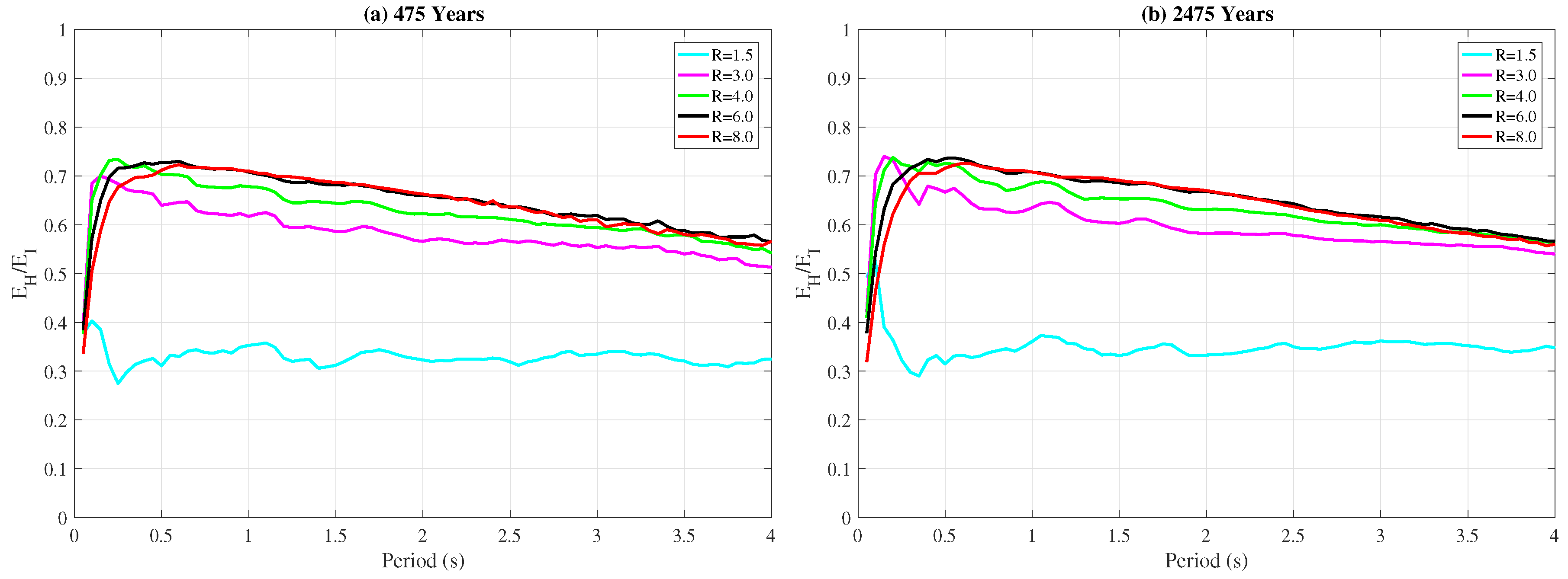
Figure 4 depicts the ratio of hysteretic energy to input energy,
/
, for 10/50 and 2/50 sets. The
/
ratio is used in this study instead of the absolute value of
as it quantifies the percentage of the input energy that is dissipated as hysteretic energy and it allows better comparison of hysteretic energy demands of different systems. For both hazard levels, the
/
ratio saturates very quickly at around
once the strength reduction factor,
R, exceeds
indicating that the level of plasticity does not significantly influence the hysteretic energy demands after a certain level of inelasticity is achieved. On the other hand, the hysteretic energy demands increase rapidly with increasing level of plasticity for strength reduction factors of
and
as the difference between the curves for
and
in
Figure 4 depicts.
Since hysteretic energy is one of the two mechanisms that dissipate the input energy together with damping, changes in the damping ratio can influence the
/
ratios. To evaluate the effect of damping ratio on the
/
ratio, the nonlinear time history analyses were repeated for a SDOF model with
damping instead of
for both hazard levels. The analyses show that the input energy demands,
, remain virtually identical while the
/
ratios converge to
for
damping for structures with
instead of
that is shown in
Figure 4 for
damping. These results indicate that changes in damping ratio significantly affect hysteretic energy demands while having virtually no effect on input energy demands. Therefore, accurate modeling of damping in structures is crucial for a reliable energy-based design.
6. Energy Demands in Multi-Degree-of-Freedom Systems
6.1. Total Energy Demands
The median total input energy demands per mass computed from nonlinear RHA conducted under 10/50 and 2/50 ground motion sets are summarized in
Table 3 for the three-, nine-, and twenty-story frames. Presented also in
Table 3 are the total input energy demands for the equivalent SDOF system obtained from the input energy spectrum (
Figure 3). In this study, the term equivalent SDOF system is used to define the SDOF system that has the same elastic period with the first mode of the corresponding MDOF system as well as the same strength reduction factor,
R. For the MDOF system the strength reduction factor is computed as
, where
is the modal mass participation factor of the first mode (
Table 1),
M is the total mass of the MDOF system,
is the elastic spectral acceleration at the first mode period and
is the yield capacity of the frame deducted from the capacity curves in
Figure 2b.
The values summarized in
Table 3 show that the median total input energy demands (
) can be estimated reliably using the equivalent SDOF approach for the three- and nine-story frames for both 475- and 2475-year return-period events as the error between the MDOF and SDOF systems remain under
for these two structures. On the other hand, the equivalent SDOF approach underestimates the median total input energy demands in the twenty-story structure by
and
for the 475- and 2475-year events, respectively.
Table 3 further presents the ratio of the hysteretic energy to the total input energy (
) for the three frames for 475- and 2475-year events. As in the case of the total input energy, the equivalent SDOF approach predicts the
ratio reliably for the three- and nine-story frames while providing a significantly unconservative estimate for the twenty-story structure for both hazard levels.
These results indicate that the total input energy demands of MDOF systems as well as the percentage of this input energy that is dissipated by hysteretic mechanisms can be reliably estimated from equivalent SDOF systems for low-rise and medium-rise structures. On the other hand, the equivalent SDOF approach significantly underestimates both the total input energy and the ratio for the twenty-story structure, whose behavior is dominated by the first mode to a lesser degree compared to the three- and nine-story structures.
6.2. Distribution of Hysteretic Energy Demands among Components of MDOF Systems
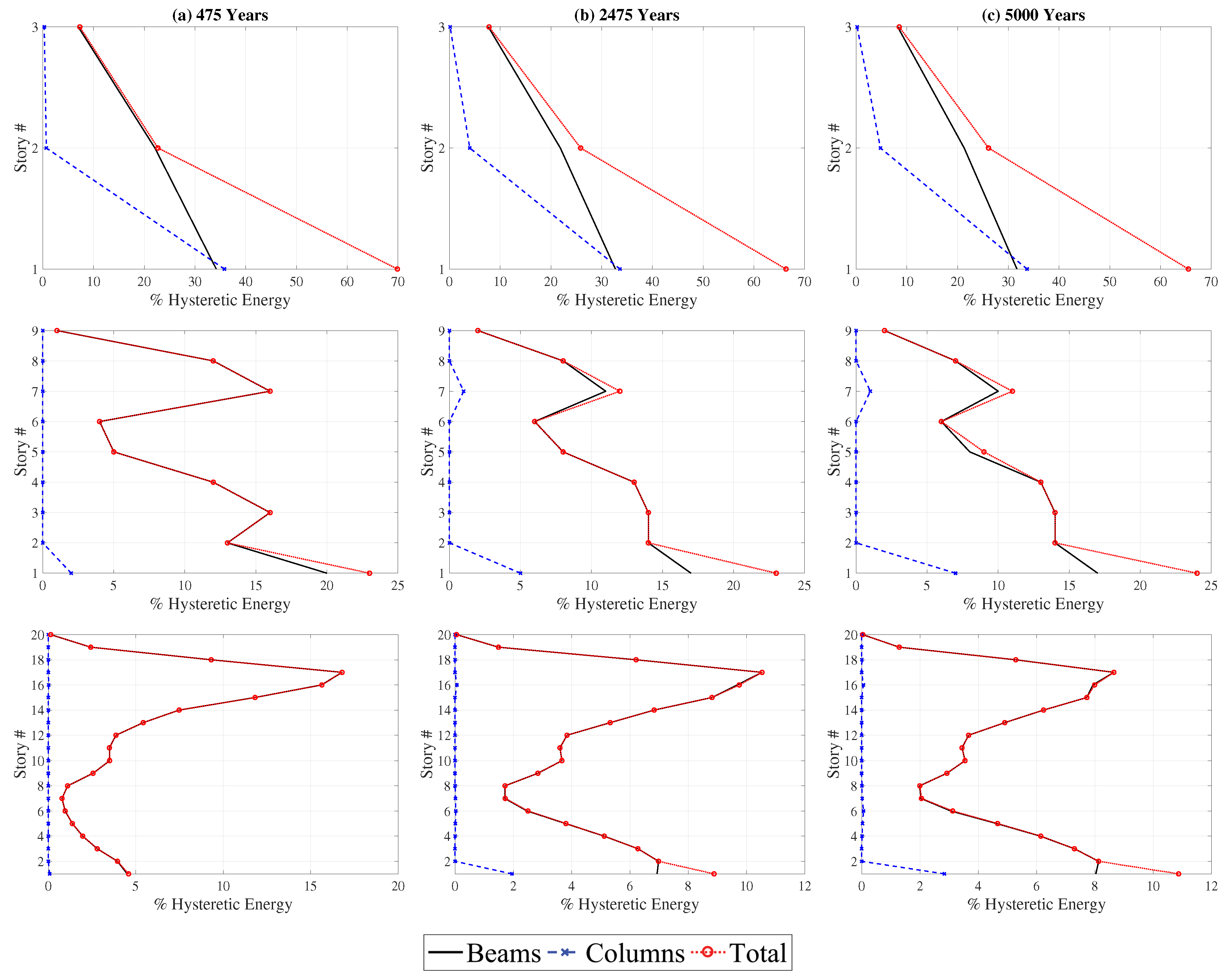
For a secure and efficient energy-based design, estimation of total hysteretic energy demand for the entire building will rarely be sufficient. The distribution of this demand among different components of the structure is arguably as important as the total demand for the entire structure. To evaluate this distribution, mean hysteretic energy demands in the columns and the beams at different floors of the structures is plotted as percentage of the total hysteretic energy demand in
Figure 5 for different hazard levels. The results indicate that the hazard level, and consequently the level of plasticity in the structure, does not play a significant role in the distribution of the hysteretic energy demands among the components of the three- and nine-story frames. For both structures, as expected, the highest hysteretic energy demands are at the ground floor of the building. Approximately 65% and 23% of the total hysteretic energy is dissipated by the ground story for the three-story and the nine-story frames, respectively, at all hazard levels. Only for the twenty-story frame, the distribution of the hysteretic energy demand among the components of the structure changes significantly with the hazard level. More specifically, for the 475-year event, the majority of the hysteretic energy is dissipated between the 14th and 17th floors of the structure. However, the hysteretic energy dissipation shifts from the upper floors of the structure towards the ground floors with an increase in the hazard level. The ratio of the hysteretic energy dissipated at the ground floor more than doubles between the 475- and 5000-year events. This can be attributed to the fact that the behavior of the twenty-story frame is dominated by elastic behavior for the 475-year event as indicated by the strength reduction factor of
(
Table 3). As the hazard level increases so does the level of inelasticity in the system, which tends to be concentrated at or near the ground level. Hence, a greater percentage of the hysteretic energy is dissipated at the bottom floors as the hazard level increases.
For all three structures, almost the entire hysteretic energy is dissipated in the beams and the bottom of the ground story columns. This is because all three structures were designed following the capacity design principles set forth by the modern seismic design codes. This observation will be revisited later in the article when the effect of the column-to-beam strength ratio on the energy demands is addressed.
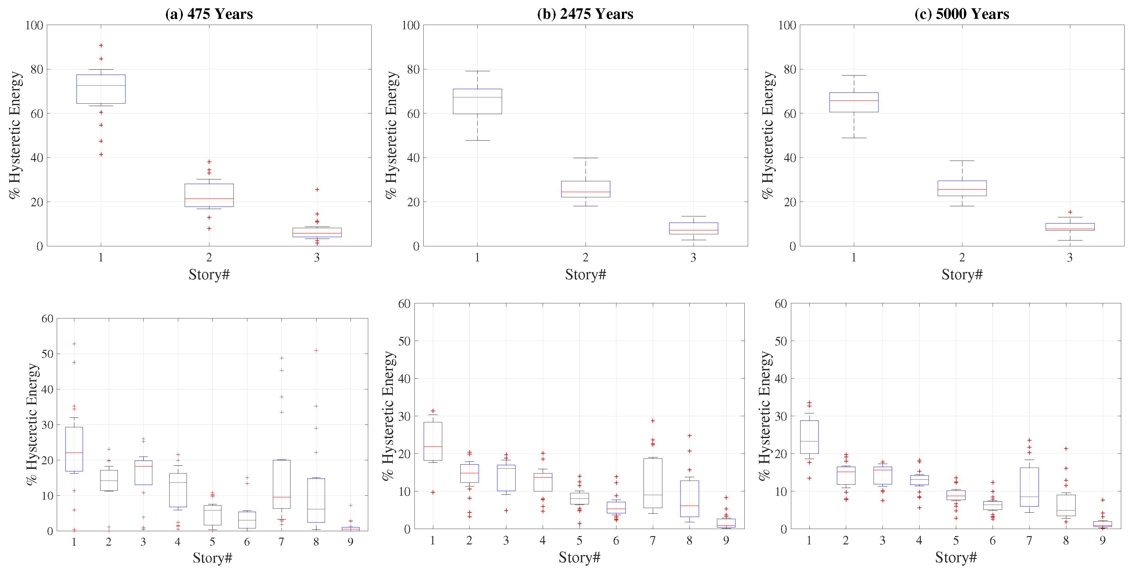
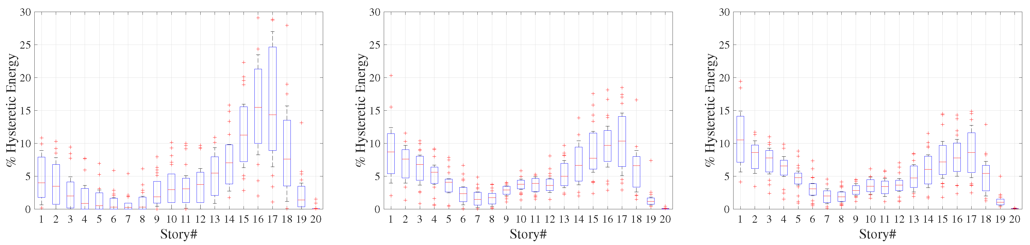
Figure 6 presents the variation of hysteretic energy demands in each story of each structure obtained from the 20 ground motions for the three hazard levels. The bottom and top edges of the boxes in
Figure 6 indicate 25th and 75th percentiles while the whiskers correspond to approximately
coverage. The red dots indicate the data points considered outliers while the red horizontal line at each floor show the median hysteretic energy demand at that floor. The wider the range of the boxes and the whiskers in
Figure 6 the higher the ground motion to ground motion variation of the hysteretic energy demand. The results shown in
Figure 6 indicate that the distribution of hysteretic energy demands over the height of the structure is prone to significant ground motion to ground motion variation at all hazard levels.
The ground motion to ground motion variation tends to decrease with an increase in the hazard level with both the 75 and percentile data becoming more compact for the set in comparison to the set where the variation is much higher for all three structures.
6.3. Effect of Damping Model on Hysteretic Energy Demands of MDOF Systems
As the total input energy is dissipated by two mechanisms, i.e., damping and hysteretic behavior, these two mechanisms have the potential to influence each other as documented earlier for the SDOF systems. Modeling of viscous damping in MDOF systems introduces additional uncertainties in estimating the behavior of MDOF systems compared to the SDOF systems. The sensitivity of different engineering demand parameters such as displacements and accelerations to the damping model used in the analysis has been previously documented [
26]. A similar but smaller scale study has been conducted here to assess the influence of damping models on hysteretic energy demands. The effects of four different damping models on the energy demands of MDOF systems is investigated: (i) Mass-proportional damping (ii) stiffness-proportional damping (iii) Rayleigh damping anchored at the first and third mode periods, and (iv) Rayleigh damping anchored at the first mode period and
T = 0.2 s. A damping ratio of
has been used in all cases. In addition, the analyses were repeated for the mass-proportional damping model and the Rayleigh damping model anchored at the first mode period and
T = 0.2 s for a damping ratio of
. These analyses have been conducted only for the
set.
The analyses results show that the damping model used in the nonlinear response history analysis does not have a significant effect on the total input energy demands. The highest difference between the total input energy demands among the different four different damping models was observed as 9.3% for the twenty-story frame. This difference reduces to 8.9% and 1.9% for the nine- and three-story structures, respectively. In addition, decreasing the damping ratio from to results in an insignificant decrease in the median total input energy demand. These results show that the total input energy demand, , is not significantly influenced by the damping model used in the analysis of MDOF systems.
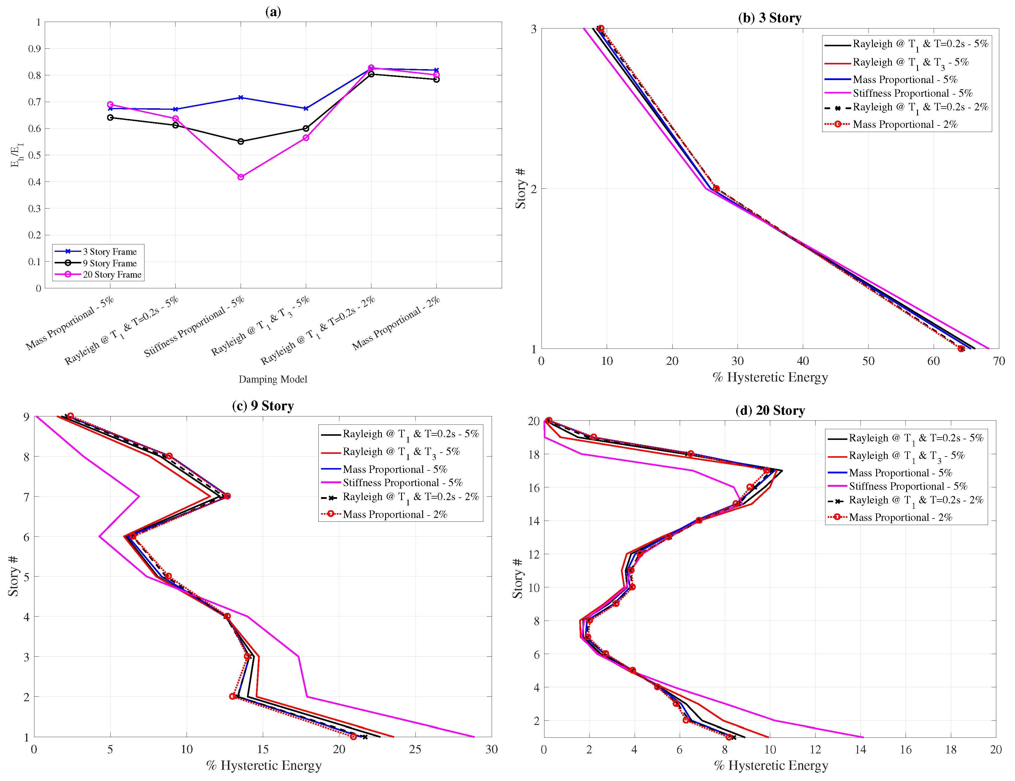
To evaluate the effect of the damping model on the total hysteretic energy demands, the variation of
with the damping model is plotted in
Figure 7a. This figure shows that the total hysteretic energy demands are also not significantly influenced by the damping model as long as the damping ratio is kept constant. The only exception to this observation is the stiffness-proportional model for the twenty-story frame. The decrease in the
value for this structure when the stiffness-proportional damping is used can be explained by the fact that the stiffness-proportional model provides very high levels of damping to the higher modes, which significantly influence the behavior of the twenty-story structure. Hence, a higher percentage of the input energy is dissipated by the damping mechanism when stiffness-proportional damping is used for the twenty-story structure. On the other hand, when the damping ratio is decreased from
to
, the hysteretic energy demands increase by approximately
for both damping models investigated for all three frames. This observation is consistent with those obtained from SDOF analyses for different damping ratios.
Finally, the effect of the damping model on the distribution of hysteretic energy demand over the height of the building is investigated,
Figure 7b–d. Apart from the stiffness-proportional damping model, all damping models lead to very similar hysteretic energy distributions over the height of the building for all three structures. Only stiffness-proportional damping model, which has previously shown to be unfit for nonlinear analysis of MDOF systems [
19,
26], leads to significantly different hysteretic energy distribution for the nine- and twenty-story structures compared to the other damping models. The influence of the damping model seems negligible for the three-story frame as the behavior of this structure is dominated by the first mode.
6.4. Effect of Column-to-Beam Strength Ratio on Hysteretic Energy Demands of MDOF Systems
The plastification hierarchy at a joint of moment-resisting frames depends mainly on the relative strength of adjoining beams and columns. Considering that the hysteretic energy demands start to accumulate with the plastification of the elements, it can be expected that the relative strength of adjoining components affect the distribution of hysteretic energy demands between these components. In order to quantify this effect, nonlinear time history analyses conducted on the buildings were repeated by varying the column-to-beam-strength ratio () of the structures.
The original buildings have a variable column-to-beam strength ratio over the height of the building with a minimum value of 1.4, 1.4, and 2.1 for the three-, nine-, and twenty-story buildings, respectively. For the three- and nine-story buildings, four additional frames have been generated by modifying the moment capacity of the columns such that the column-to-beam strength ratio () is and for these two structures. For the twenty-story building, five new frames were created to achieve column-to-beam strength ratios of and . It should be noted that the moment capacity of all the columns in the structure has been multiplied with the same factor to achieve the desired values simulating a case where the column cross-sections are kept the same while the yield strength of steel for columns is modified leading to different column-to-beam strength ratios. The moment capacity of the beams remains constant. Keeping the column and beam cross-sections same ensures that the modal periods, elastic mode shapes and the modal participation factors of the respective frames are identical to each other ensuring a fair comparison of energy demands between the variants of the three buildings.
Nonlinear response history analyses show that the total input energy demand, (), remains virtually identical for different column-to-beam strength ratios for all three hazard levels and for all three buildings. For example, for the 2475 year event, the total input energy per mass varies between 2.74 / for = 1.0 and 2.87 / for = 1.6 for the nine-story building. This observation is valid also for 475 and 5000 year events and the other two buildings with the variation in total input energy demand less than for all hazard levels and structures.
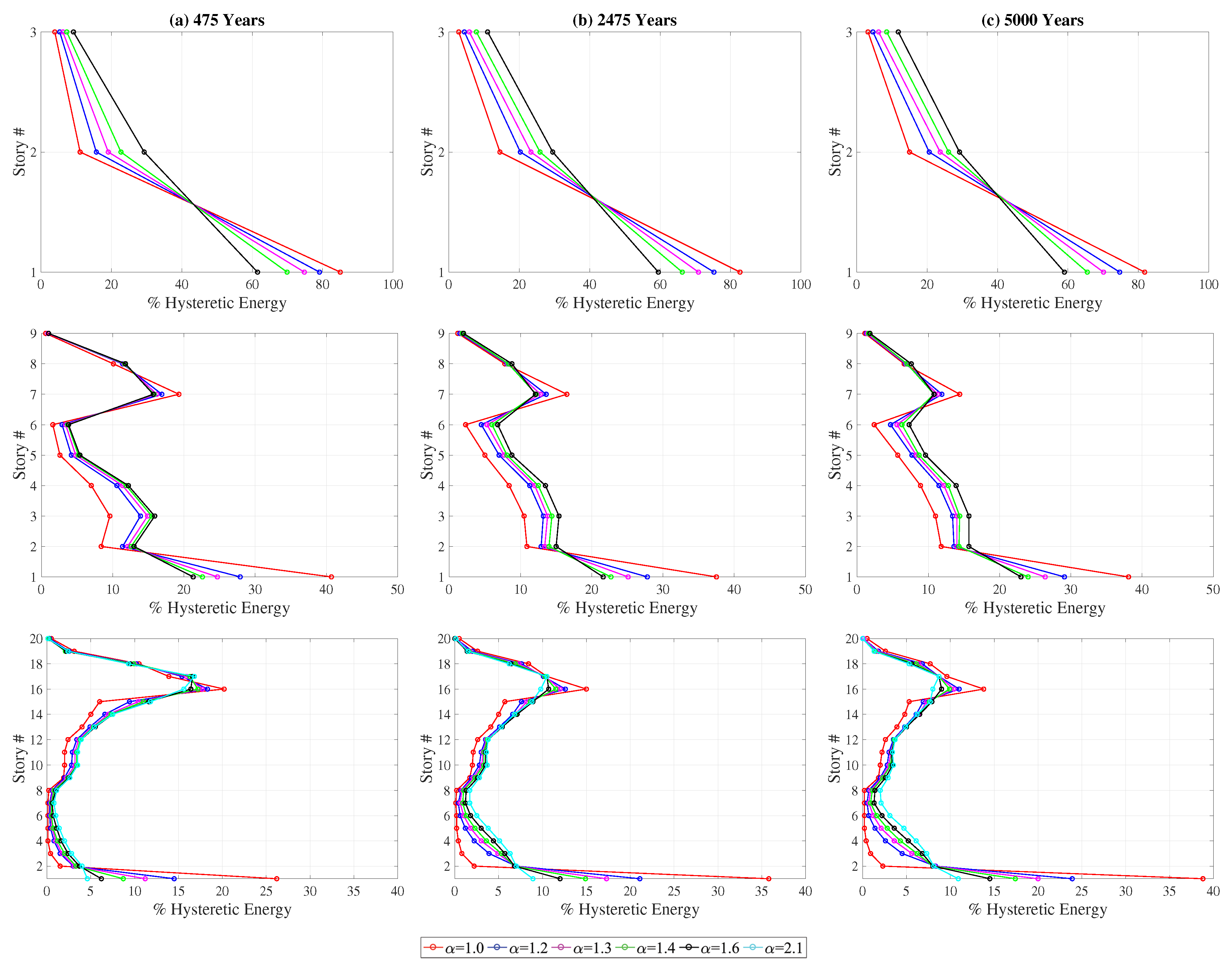
The mean hysteretic energy demands at each floor (
Figure 8) indicate that the effect of column-to-beam strength ratio on the distribution of hysteretic energy demands over the height of the building is similar for the three hazard levels. For all hazard levels, the percentage of the hysteretic energy dissipated at the ground story increases significantly with a decrease in the column-to-beam strength ratio. This increase is even more pronounced for the twenty-story structure for which the inelasticity level is quite limited for the 475-year event and increases with an increase in the hazard level. In addition, the distribution of the hysteretic energy demand becomes more evenly distributed over the height of the building as the column-to-beam strength ratio increases for all three structures.
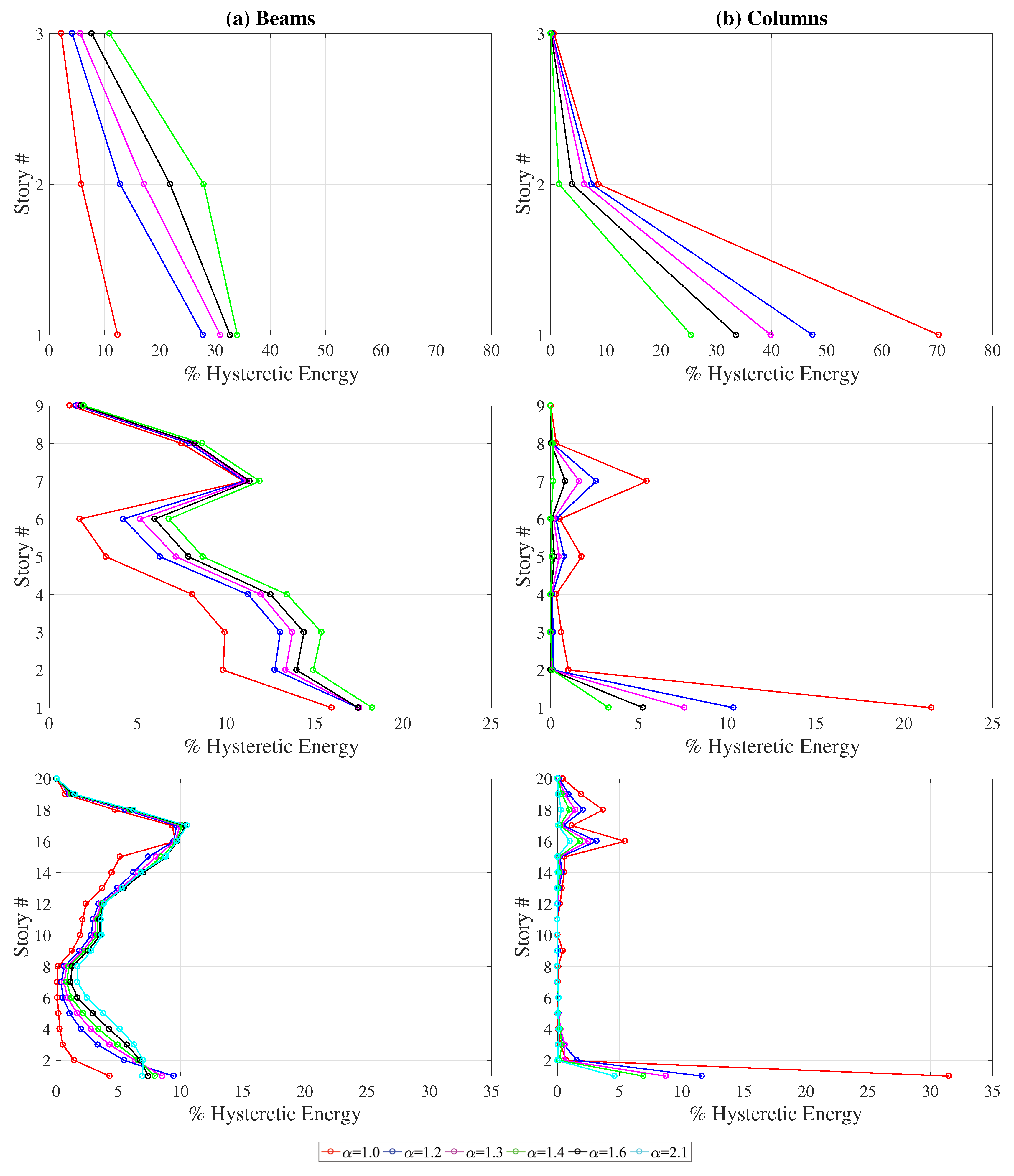
Figure 9 depicts the variation of mean hysteretic energy demands among the (a) beams and (b) columns of the buildings with column-to-beam strength ratio for the
set. The percentage of the hysteretic energy dissipated by the beams systematically increase with an increase in the column-to-beam strength ratio. On the other hand, the hysteretic energy dissipation shifts from beams to the columns as the column-to-beam strength ratio decreases. The most significant increase is in the ground story columns where the bottom of the column is not protected by the capacity design approach. The results for
and
set are almost identical to those plotted in
Figure 9 for the
set and have been omitted for brevity. Results presented herein show that hysteretic energy distribution among the components of MDOF systems is very sensitive to the relative strength of adjoining columns and beams and any approximate procedure that aims to reliably estimate this distribution has to take this parameter into account.
7. Conclusions
In-depth evaluation of hysteretic energy demands in multi-degree-of-freedom systems as well as their distribution among different components of the structure has been provided. The accuracy of equivalent SDOF approaches in estimating the input and hysteretic energy demands in MDOF systems has been investigated. Finally, the effects of damping model and the column-to-beam-strength ratio on the hysteretic energy distrubution among the components of MDOF systems have been evaluated. As a result of the nonlinear response history analyses conducted on SDOF and MDOF systems, the following conclusions can be drawn:
For low- and mid-rise buildings, the total input energy demands as well as total hysteretic energy demands of MDOF systems can be satisfactorily estimated by equivalent SDOF analyses for all hazard levels. This observation is in line with earlier studies [
27].
For buildings that are more prone to higher mode effects, the equivalent SDOF analysis significantly underestimates both the input and hysteretic energy demands indicating a limitation for the use of SDOF approaches. Further analysis on structures that cover a wider range of total number of floors and fundamental periods is necessary to provide clear guidelines on the applicability of the SDOF approach to estimate the total input and hysteretic energy demands of MDOF systems.
The distribution of hysteretic energy demands over the height of the structure is not significantly affected by the hazard level for low- and mid-rise buildings. For the high-rise building, the hysteretic energy demands migrate to the lower floors with an increase in the hazard level.
The distribution of hysteretic energy demands over the height of the structure is prone to significant ground motion to ground motion variation for all three hazard levels. This variation is most pronounced for the set and tends to decrease with an increase in the hazard level.
The damping ratio of the system has a significant influence on the percentage of the input energy dissipated as hysteretic energy for both SDOF and MDOF systems.
The damping model used in the nonlinear response history analysis of the MDOF system does not have a significant effect on the total hysteretic energy demand and its distribution among different components of the frame.
The column-to-beam strength ratio does not significantly influence the total input energy demand or total hysteretic energy demand of MDOF systems. However, the distribution of the total hysteretic energy demand among the components of the structure is significantly affected by the column-to-beam strength ratio. The hysteretic energy demand becomes more concentrated at the ground floor as this ratio decreases. Higher column-to-beam strength ratios lead to a more even distribution of hysteretic energy demands over the height of the building.
This article aims to provide the first comprehensive look into the hysteretic energy demands on MDOF systems and has limitations in terms of the structural type and structural models used. Future research is necessary to improve the fundamental understanding of energy demands on MDOF systems. In particular, the approach used in the modeling of nonlinear behavior of the structural elements is likely to have a significant influence on both the total energy demands and the distribution of these demands among the components of MDOF systems. Consideration of structural models with a more complex hysteretic behavior than the bilinear elastic-perfectly-plastic model used herein is vital to understand their effect on energy demands. More specifically, rigorous studies on the impact of several parameters such as axial load level on columns, P-Delta effects, pinching behavior, cyclic degradation, and the level of strain hardening on the hysteretic energy demands of MDOF systems is necessary to develop a thorough understanding of the flow of hysteretic energy demands in MDOF systems.


