Abstract
The application of phase change materials (PCM) in the thermal envelope of buildings has proven to be an alternative to reduce energy consumption and to improve thermal comfort conditions. The present work evaluates the thermal behavior of gypsum boards modified with a microencapsulated PCM (mPCM) in a cubic test enclosure, considering the climatic conditions of Santiago de Chile in the September–November period of 2017. The design of the test enclosure was performed considering the minimization of parameters that affect the variation of its inner temperature and favoring the heat flow through the gypsum boards. Experimentally, the results reflect the main effects of the implementation of a mPCM, among which the displacement of the maximum heat load and the decrease in the daily oscillation of the internal temperature of the test enclosure (up to 2 °C) stand out. In addition, the mPCM modified gypsum board was thermally characterized to carry out a thermal simulation of the enclosures using EnergyPlus™. The obtained numerical results agree with those obtained experimentally, including the behavior of the transient heat flux through the gypsum boards. Moreover, it was found that considering a null infiltration rate gives place to unrealistic results, suggesting that this parameter should be controlled.
1. Introduction
Among the commitments of the energy policy of Chile for 2035 are to reduce CO2 emissions by 30% regarding to 2007, and the ensuring of continuous and quality access to energy for dwellings of vulnerable families [1]. Energy may be stored as chemical, electric, kinetic, potential, or thermal [2]. Among the many existing technological options to increase energy efficiency in buildings, it has been recommended to put attention to Thermal Energy Storage (TES) [3]. Thermal energy storage systems use energy density of materials or latent heat associated with a phase transition to provide a heating or cooling source [4]. Phase change materials (PCMs) have been used increasingly as Latent Heat Thermal Energy Storage (LHTES) systems for heating and cooling applications. LHTES is considered a passive method of heat modulation, where PCMs can absorb heat from the environment and release it indoors when required [5,6]. The integration of LHTES in buildings can be done using their floor, walls, ceilings, and external solar facades [7].
The process of charging and discharging thermal energy from and to a PCM depends on the thermal oscillations of the environment. Thus, the phase change temperature is the main characteristic that allows to differentiate each PCM and therefore to choose the most appropriate for an application. PCMs are commonly classified as inorganic, eutectic mixtures, and organic (O-PCMs) [8]. Among O-PCMs, there are different substances such as paraffins, fatty acids, fatty acid esters, long-chain alcohols, polyglycols, and their mixtures [9,10]. Thanks to their properties, O-PCMs can be used in applications near human comfort temperature, moreover, O-PCMs are chemically and physically stable, and they are less prone to subcooling than inorganic PCMs [11].
One of the main applications of O-PCMs is the increase of thermal inertia of building materials, which gives place to decreasing inner temperature fluctuations, shifting heat load peaks, and reducing the energy consumption of buildings associated with air conditioning [12,13,14,15]. Therefore, O-PCMs work exceptionally well on buildings of low thermal mass [16], where temperatures change abruptly, giving place to high energy consumption associated with thermally conditioning the building. The results of several investigations have proven that a proper design is necessary to take advantage of the capabilities of PCMs like the reduction of energy consumption, and the improvement of thermal comfort in buildings [17]. In a passive strategy, the integration of PCMs into building materials allows releasing of heat during the colder hours, beginning the solidification process. During the warmer hours, the melting process of PCM gives place to heat absorption. The integration of O-PCMs into lightweight building materials increases their energy density or volumetric heat capacity. Typical building materials such as gypsum plaster store up to 1 kJ/(kg K) as sensible heat, whereas average paraffin materials store energy as latent heat of approximately 100 kJ/kg [18].
There are some reported limitations in using PCMs in building materials [19]: (i) PCMs may interact with the building structure; (ii) leakage of PCMs; (iii) PCMs have low thermal conductivities. In order to overcome these issues, microencapsulated phase change materials (mPCM) have been integrated into building materials such as gypsum plaster, concrete, and mortar [20]. There are currently several forms of PCM encapsulation. Generally, the PCM is incorporated into a polymer matrix and depending on the final size of the encapsulated material is classified as nano-encapsulated (ϕp < 1 μm), micro-encapsulated (1 μm < ϕp < 1 mm) for particles, and macro-encapsulation (ϕp > 1 mm) [21]. There are several processes to micro-encapsulate PCMs, A. Jamekhorshid et al. [22] propose to classify encapsulation methods in physical, physicochemical, and chemical procedures.
Barreneche et al. [23] characterized the effective thermal conductivity and the thermal inertia of gypsum and Portland cement modified with a mPCM (5 wt% and 15 wt%) by using two different apparatuses. The authors found that the addition of mPCM causes a reduction (25–35%) of the thermal conductivity of both building materials. Moreover, a 15 wt% load of mPCM causes a higher increase of the thermal inertia of gypsum boards. Zhou et al. [24] performed numerical simulations of the thermal performance of shape-stabilized PCM (melting point of 21 °C) plates integrated into the inner surfaces of walls and the ceiling of a passive house located in Beijing, China, during winter. The results showed that shape-stabilized PCM gypsum plates can diminish the indoor temperature variation by up to 56%. Lachheb et al. [25] experimentally characterized a plaster composite incorporating 10% of microencapsulated paraffin (Micronal®, BASF Company, Dayton, USA) by the guarded hot plate method. Moreover, the authors made a parametric study to analyze the effect of the wallboard thickness (1–3 cm), and the mass fraction (0–30%) of mPCM. The obtained results show that there are no essential differences in the inner surface temperature variation for mPCM mass fractions of 20% and 30%. Li et al. [26] characterized the thermal properties (thermal conductivity, apparent heat capacity and enthalpy) as function of temperature of a mPCM-gypsum wall board composite (20%). The authors found that thermal conductivity increases linearly with temperature, the apparent specific heat capacity of the composite is 2.71 times larger than that of gypsum wallboard. Regarding the enthalpy, the authors found that an appropriate heating rate, according to the application, is necessary.
In 2007, Cabeza et al. [27] performed experiments with concrete cubicles (2 m × 2 m × 3 m) located in Lleida (Spain) with and without windows to analyze the effect of the incorporation (5 wt%) of a commercial mPCM (melting point of 26.8 °C) into the south, west, and roof walls. The measured temperature values during spring days showed that the south wall of the cubicle without mPCM at midday is 2 °C higher than that of the cubicle with PCM. Arce et al. [28] mention that a PCM should complete the phase change cycle to work correctly. Then, it is a problem that during the colder winter days and warmer summer day, the PCM might not reach its melting and solidification temperature, respectively. In 2018, Zhu et al. [29] made a review about experimental and numerical applications with shape stabilized PCMs into building envelope components. This review work identified several factors that affect the performance of a PCM, including its melting temperature, location and orientation of the building, and weather conditions.
There is a trend of using hybrid composites with different melting points to be used during the colder and warmer seasons of the year. Kheradmand et al. [30] experimentally and numerically (Ansys-Fluent) evaluated a hybrid PCM plastering mortar in a test cell of reduced dimensions submitted to simulated weather conditions. The authors found that the use of three PCMs of different suitable melting points reduces heating and cooling temperature demands. Berardi and Soudian [31] implemented a composite of two macroencapsulated PCMs with melting temperatures of 21.7 °C (Energain) and 25 °C (BioPCM™) in the walls and the ceiling of a test cell, which resembles apartments with 80% window to wall ratio located in Toronto (Canada). The studies performed during one-year show that the hybrid PCM system reduce the temperature fluctuations during fall and summer. Previously, the same authors [32] made a parametric analysis of an apartment with the same hybrid composite and window to wall ratio by using Energyplus™ showing promising results in two different climates (Toronto and Vancouver).
In the review of Kalnæs and Jelle [33] about PCMs and their application in buildings, the authors mentioned that there are few studies on the effects of PCMs in roofing. Moreover, the authors claimed that the use of PCMs on the roof would absorb the incoming solar radiation and heat from the surroundings reducing the inner temperature fluctuations. Piselli et al. [34] found that the inclusion of PCM in waterproof membranes improves the thermal performance of roofs under climatic conditions in the cities of Rome (Italy) and Abu Dhabi (UAE). Pasupathy and Velraj [35] made a study about the thermal performance of double layer PCM in the roof of a building located in Chennai (India). In order to reduce the inner temperature fluctuation, the authors recommended a double layer PCM with different melting points of 27 °C and 32 °C. Bamonte et al. [36] performed a numerical study, using the finite volume method, of concrete panels with aggregates containing PCMs (capric acid and glycerine) under temperature conditions of Bucharest (Romania) and Seville (Spain). The authors claimed that the implementation of these PCMs may reduce the energy consumption for cooling and heating by up to 20% and 10%, respectively.
Jaworski [37] studied the thermal performance of mPCM-plaster ceiling panels with air ducts that works as a heat exchanger. The system was used in an office building to improve the free cooling strategy. Saffari et al. [38] studied the cool roof strategy to mitigate the effect of urban heat island. Their results showed that PCMs with higher melting point are more suitable for reducing thermal loads in summer. Cornaro et al. [39] implemented a commercial PCM panel (RUBITHERM®) on the floor of a test enclosure under the weather conditions of Rome (Italy). The authors used the experimental results to validate a tool implemented in Indoor Climate and Energy software. The numerical results obtained for three different locations showed that only the energy savings using PCM and implementing night ventilation meet the Italian energy performance regulation. Ramakrishnan et al. [40] implemented a PCM stabilized cement mortar (FS-PCM) in the envelopes of a test box, comparing its thermal behavior with similar test boxes built on cement plasterboard (OCB) and gypsum plasterboard (GPB). The experimental results showed that the implementation of FS-PCM reduced the peak temperature by up to 2.4 °C, compared to GPB and OCB test boxes.
In the present work, the temperature variation inside a cubic test enclosure containing gypsum boards modified with a mPCM in the roof is recorded experimentally (September–November 2017). In addition, the behavior of the heat flux across the gypsum boards with and without mPCM is determined, being able to observe more clearly the displacement of the heat load. Gypsum boards modified with mPCM are thermally characterized, determining thermal conductivity, heat capacity, and enthalpy according to the temperature. These properties were incorporated into a thermally simulated physical model with EnergyPlus™. Numerical results also include the variation of the inner temperature of the enclosure in a period of moderate and warm temperatures in Santiago de Chile, as well as heat fluxes through the plates. In general, the numerical results show a behavior like those recorded experimentally.
2. Materials and Methods
This section describes the experimental procedures for the preparation of gypsum samples modified with mPCM, the determination of their thermophysical properties, and the experimental assembly performed to study the behavior of gypsum boards modified with mPCM in a test enclosure. To manufacture the modified gypsum boards, the gypsum plaster (TOPEX®) and mPCM (MikroCaps 28), whose properties are shown in Table 1, are poured into a container according to the analyzed mass concentration (20 wt%). Initially, a lower mass concentration of 10 wt% was considered but given its low enthalpy its use was discarded. Moreover, the obtained gypsum boards of higher mass concentration (30 wt%) presented a poor mechanical stability, which prevented its use in the test enclosure. Subsequently, this dry mixture is homogenized to then, add the amount of distilled water required and obtain the mass proportion Plaster/water = 0.7. Finally, the wet mixture is blended until it acquires a slightly viscous consistency and is poured into melamine molds of 35 [cm2] and 1 [cm] thick. The wet mixture is dried for one day at ambient temperature, then the wooden mold is removed, and the plates are placed in an oven (Heraeus T 6120) at 30 °C for four days.

Table 1.
mPCM (MicroKaps 28) technical information supplied by the manufacturer [42].
The gypsum samples for the characterization of the thermophysical properties are of different geometry and dimensions due to the requirements of the equipment used, so these were obtained by pouring the wet mixtures into PVC molds of 3.6 mm in diameter and 8 cm high. Figure 1 shows SEM images (Jeol, JSM 5410) of the gypsum samples modified with mPCM can be seen, where the formation of microcapsule agglomerates between the plaster crystals is evident, therefore the final modified gypsum boards are not homogenous. The measurement of the thermal conductivity and the thermal diffusivity of the samples has been made by the thermal properties analyzer KD2-Pro (Decagon devices) using the dual needle probe (sh1). The measurements were made in triplicate controlling the temperature (±0.1 °C) in the range from 0 °C to 40 °C. In addition, a differential scanning calorimeter DSC 4000 (PerkinElmer) has been used to obtain the enthalpy (2% error) according to the temperature (±0.1 °C), which is fundamental to model the thermal behavior of phase change materials correctly. One collected three different samples from the modified gypsum boards, and the obtained DSC results were quite similar between samples with percentage differences lower than 0.2%.
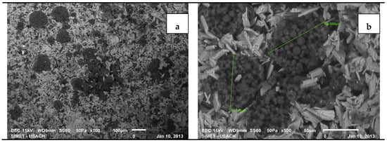
Figure 1.
Microstructure of the fracture surface of gypsum plaster samples modified with microencapsulated phase change materials (mPCM): (a) ×100 and (b) ×500.
Figure 2 shows the obtained results of thermal conductivity and thermal diffusivity. These results show a decreasing tendency of both properties with temperature when the PCM is in solid state (<25 °C). The enthalpy as a function of temperature was estimated from the DSC measurements according to equations available in the literature [41]. The enthalpy of mPCM-modified plaster with the implemented weight fraction is shown in Figure 3.
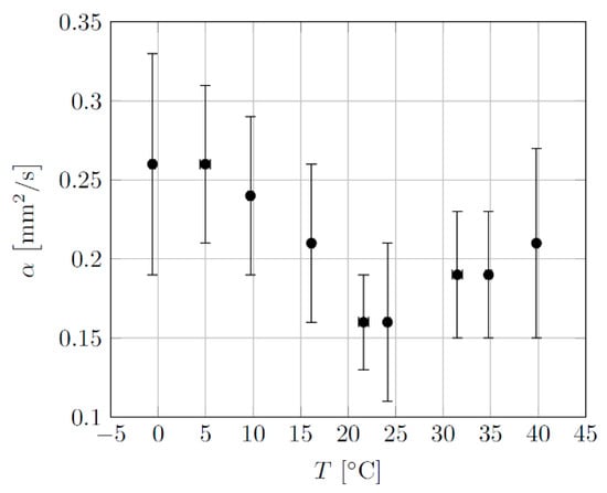
Figure 2.
Thermal conductivity and thermal diffusivity of mPCM-modified plaster (20 wt%).
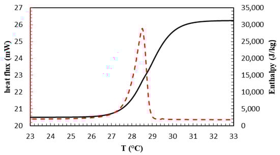
Figure 3.
Heat flux (segmented line) and obtained from differential scanning calorimeter (DSC) measurement calculated enthalpy (continuous line) [41] of mPCM-modified plaster (20%).
Experimental Set-Up
The experimental set-up consists of two cubicles of 0.512 m3 in volume, one with three gypsum boards modified with mPCM and the other with three not modified gypsum boards as control (Figure 4). The walls and base of the enclosures are composed of 1 m2 sandwich-type refrigeration panels, made of expanded polystyrene (100 mm thick) coated by galvanized steel on both sides. This material has a U value of 0.364 W/m2 K, as obtained by the calculation procedure according to NCh 853. Of.91.
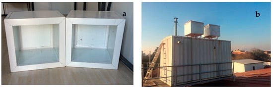
Figure 4.
(a) Test enclosures of refrigeration panels (b) and installation of test enclosures.
Pre-painted metallic profiles of the same type of steel were used to assemble the enclosures, as wells as sanitary profiles finished in PVC, and as fasteners, Philips stainless steel self-drilling screws and countersunk screws were used. The roofing is made of a zinc plate, structural plywood, calcium silicate board as a thermal insulator, and three gypsum boards with and without mPCM according to the different study configurations. A metal grid is used to affix the gypsum boards. In addition, synthetic rubber bands are employed to reduce air infiltration (Figure 5). Each of the three gypsum boards has an area of 35 cm2, a thickness of 1 cm, and, in the case of the modified boards, a fraction of 20 wt% of mPCM.
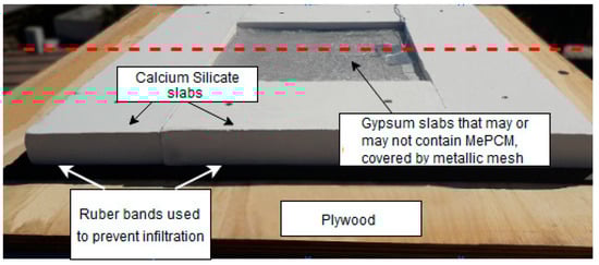
Figure 5.
Support structure of the gypsum boards. Each of the three gypsum boards has an area of 35 cm2, a thickness of 1 cm, and, in the case of modified plates, a fraction of 20 wt% of mPCM.
In Figure 6, a diagram of both test enclosures indoors can be observed; these were installed on the roof of the Department of Mechanical Engineering of the University of Santiago, where they were subjected to the same weather, atmospheric conditions and were kept at a reasonable distance so they would not affect each other. Another important feature of the installation is that test enclosures were separated from the “floor” using platforms of approximately 30 cm high, to avoid any effect of the enclosure on which the experimental installation was performed (Figure 4b). The design of the test enclosures points to the minimization of heat gains or losses through walls and floor, favoring the heat flow through the ceiling where the plaster boards are located.
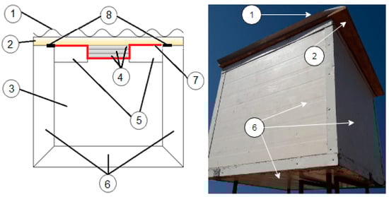
Figure 6.
Diagram of the test enclosures. 1. Galvanized steel plate, 2. Plywood, 3. Internal air volume, 4. Plaster boards, 5. Calcium silicate boards, 6. Cold room boards, 7. Grillage, 8. Synthetic rubber tapes.
The temperatures were recorded in four positions in each test enclosure: on the lower internal base, on the surface of the gypsum board in contact with the air, on the outer surface of the roofing, and the temperature of the air just below of the gypsum board. The measurements were made during the spring season (September–November) of 2017 in the premises of the Department of Mechanical Engineering of the University of Santiago de Chile (33° 26 ʹ47.401 “S, 70° 40ʹ 53.311” W). The data acquisition system is a seven-channel temperature measurement system prototype whose main features are: (i) K-type thermocouples, (ii) MAX31855 analog signal converter (Maxim Integrated Products), (iii) processing and communication through Arduino UNO (Arduino), (iv) user control interface by LabVIEW (National Instruments). The sampling ratio was every 10 min, and the sensitivity of the temperatures reading was ±0.1 °C.
3. Results
3.1. Experimental Measurements
An experimental analysis is carried out to study the behavior of the temperatures inside both experimental set-up during three periods corresponding to the southern spring in Santiago de Chile (Csb): (a) 16–30 September, (b) 12–26 October, and (c) 29 October–12 November. The average outdoor temperature and the mode in each analyzed period are (a) 16.3 °C and 13.7 °C, (b) 17.6 °C and 16.5 °C, and (c) 18.3 °C and 15.8 °C, respectively. Figure 7, Figure 8 and Figure 9 show the behavior of the internal and external temperature of the test enclosure without and with gypsum boards modified with mPCM for periods (a), (b), and (c). Moreover, it can be seen details about the effect of mPCM on the peak temperatures.
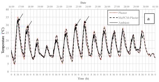
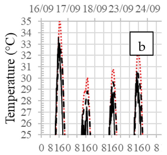
Figure 7.
(a) Average temperatures of the test enclosures during the first period and (b) detail of days when there is a decrease in the maximum internal temperature in the enclosure with gypsum boards modified with mPCM.
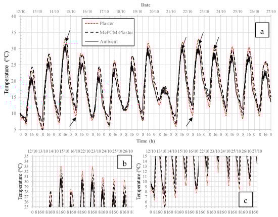
Figure 8.
(a) Average temperatures of the test enclosures during the second period (b,c) and detail at the end of the period when there is a decrease in the temperature oscillation of the enclosure with gypsum boards modified with mPCM.
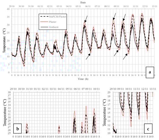
Figure 9.
(a) Average temperatures of the test enclosures during the third period (b,c) and detail at the end of the period when there is a decrease in the temperature oscillation of the enclosure with gypsum boards modified with mPCM.
In the second period of analyzed tests (Figure 8), the effect of the mPCM incorporated in the gypsum board is evident for a greater number of days (7). In this period, it is also observed that during the same amount of days the micro-encapsulated phase change material influences the variation of the minimum temperature, finding that, in the case of the enclosure with plates modified with mPCM, these are lower than in the reference room. It is also interesting to note that at the end of this period, the effect of the phase change material is evident in the decrease in the oscillation of the internal temperature of the enclosure.
Figure 9 shows the behavior of temperatures during the third period of tests, from 29 October to 12 November. In this period, only three days are observed in which the incorporation of mPCM to the gypsum board is evident. However, the most interesting thing during this period is that there are two days (8 and 11 November) where the average internal temperature in both enclosures is much higher than the outside temperature. This increase can be explained from the rise in the minimum temperature during the previous days, which causes the mPCM not to be able to discharge during the hours of low temperatures. As in the previous period, the effect of the phase change material is more evident in the decrease of the oscillation of the enclosure’s internal temperature.
In Figure 10 and Figure 11, the maximum and minimum daily temperatures in both test enclosures are observed, measured in the lower internal base and in the air just below the gypsum board, respectively. In Figure 10, no significant effect of the incorporation of the phase change material is observed due to the condition of the ventilated floor, which is also a common characteristic that can be seen repeatedly in constructions in the Chilean coast. However, the effect of the mPCM is observed in the decrease of the maximum temperature measured in the adjacent air on the gypsum board during the analyzed period (Figure 11), approximately between 1 °C and 4 °C. Regarding the minimum temperature, it is noted that the effect of the mPCM is evidenced only in some days, which reflects in a higher minimum temperature, between 1.5 °C and 3.0 °C, specifically at the end of the analyzed period.
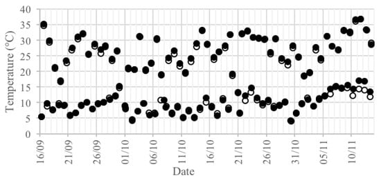
Figure 10.
Maximum and minimum daily temperatures of the lower surface of the test enclosure with gypsum boards with (filling) and without (empty) mPCM.
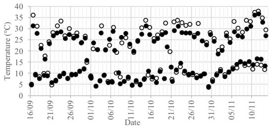
Figure 11.
Maximum and minimum daily temperatures of the air adjacent to the gypsum board with (fill) and without (empty) mPCM.
3.2. Heat Flow Calculation
According to the configuration of the experimental set-up, the heat flow to (or from) the test enclosure is mainly by conduction, through the layer of structural plywood and the three gypsum boards layers (Figure 12). In the case of the test enclosure with non-modified gypsum boards, the physical situation can be modeled as a pair of conductive thermal resistance series associated with structural plywood Lt = 18 mm, kt = 0.130 W/mK and gypsum board layers without mPCM Lp = 30 mm, kp = 0.422 W/mK. In this way, the overall transfer coefficient is calculated from the equation:
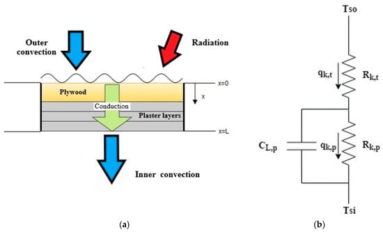
Figure 12.
Roofing model of the test enclosures (a) and equivalent thermal circuit for the approximate calculation of heat fluxes (b).
Then, the heat flux per unit area is calculated through the equation:
where the temperatures Tso and Tsi correspond to the external surface temperature of the structural plywood (x = 0) and the internal temperature of the third gypsum board (x = L). In the case of the enclosure with gypsum boards modified with mPCM (Lp = 30 mm, kp = 0.306 W/mK) a capacitor is added to the thermal circuit parallel to the conductive thermal resistance of the gypsum boards. This capacitor models the thermal inertia of the gypsum boards with mPCM, counting the heat absorbed or released depending on the environmental conditions. In this way, using Equations (1) and (2), it is possible to obtain approximately the heat flows by conduction during the test periods in the enclosures with gypsum boards not modified and modified with mPCM (Figure 13). According to this analysis, the heat accumulated on gypsum boards modified with mPCM can be estimated approximately as the difference of heat fluxes through the thermal model of the test enclosure with gypsum boards modified with PCM and that with non-modified gypsum boards (Figure 12).
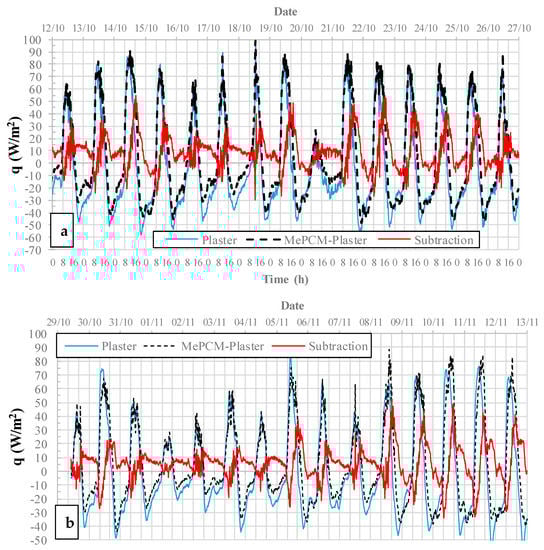
Figure 13.
Estimated heat flux through the gypsum boards in the test enclosures with and without gypsum boards modified with mPCM for the second (a) and third (b) analyzed periods.
Figure 13 shows the result of the behavior of instantaneous heat fluxes through the roofing of the test enclosures during the second and third studied periods. These figures allow to better observe the displacement in time of the peak of thermal loads due to the incorporation of mPCM, evidenced by the difference between the times at which the heat flux peaks manifest in each case.
3.3. Computational Simulation
EnergyPlus™ is a thermal simulation software for developed by collaborations between the United States Renewable Energy Laboratory (NREL), United States Department of Energy (DOE), academic institutions, and private companies. It consists of a tool that interrelates the performance of active energy systems, geometric dimensions, envelope characteristics, geographical location, and weather data to perform a computer simulation and subsequently deliver reports of energy consumption by air conditioning of spaces, lighting, temperatures, and other values required by the user. For this simulation, the software required the following fundamental information:
- (i.)
- Climatic data, including solar radiation and cloudiness of the geographical location, dry bulb temperature, relative humidity, and wind speed. This information was obtained for Santiago de Chile from the EnergyPlus ™ website [43].
- (ii.)
- Geometric information of the necessary enclosures to create a 3-D model, considering dimensions, materials, and the orientation of the enclosures.
- (iii.)
- The thermophysical properties of the enclosure’s envelope materials obtained experimentally and from information available in Chilean regulations.
- (iv.)
- The external floors of each enclosure were considered ventilated surfaces, not exposed to direct sun radiation.
- (v.)
- Air renewals per hour on the enclosure. A parameter that was set at five renewals/hour.
Figure 14a shows the numerical results of temperature behavior during the first period of tests. As in the experimental study, the simulation predicts that the temperature inside the test enclosures is higher than the outside temperature. However, this difference is much more evident than in the experimental case (Figure 7a). The simulation results predict that the effect of incorporating gypsum boards modified with mPCM is not important during this stage; this is because the outer temperature does not exceed the PCM melting temperature. It is for this reason that the simulation results for the other two experimentally analyzed periods are not shown. Figure 14b shows the results of the variation of the temperature inside the test enclosures during a warmer period than those analyzed experimentally. During this period, it is observed that the difference between the internal temperature of the enclosures and the outdoor temperature is further accentuated. It is also possible to identify the effect of the incorporation of the modified gypsum boards, visualized in the behavior of the temperature inside the enclosure, specifically in the reduction of the maximum temperature (Figure 14c). However, said reduction does not exceed 2 °C.
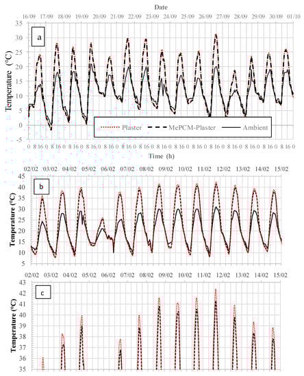
Figure 14.
Simulated average temperatures of the test enclosures during two periods of spring (a) and southern summer (b). The detail shows the decrease in temperature oscillation of the enclosure with gypsum boards with mPCM (c).
Figure 15 shows the predicted behavior of the net heat flux by conduction through the roofing of the test enclosures. As with the heat flux values estimated from the experimental measurements, a heat flux is considered positive when it flows into the test enclosure and it is negative when it flows to the outside. The results obtained for the first period (Figure 15a) do not allow to observe an apparent difference between the net heat fluxes by conduction through the roofing of both enclosures. However, in the warmest period analyzed (Figure 15b), it shows a more significant difference between the two enclosures. The difference in heat fluxes by conduction through the roofing of both enclosures corresponds, as in the experimental case (Figure 13), to the heat flux stored in the gypsum boards with mPCM.
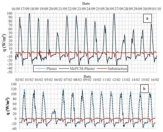
Figure 15.
Predicted heat flux through the gypsum boards in the test enclosures with and without gypsum boards modified with mPCM for the second (a) and third (b) analyzed periods.
4. Discussion
The dimensions of the test enclosure (Figure 4 and Figure 6) are no suitable to extrapolate the obtained results to a real scale building. Nevertheless, the used enclosure does not pretend to be a physical model of an actual building; instead, the goal is to assess the mPCM-modified gypsum boards under actual weather conditions minimizing the parameters that affect the variation of the enclosure’s inner temperature and favoring the heat flux through the gypsum board surfaces.
One characterized the thermal properties of the gypsum boards modified with a paraffinic mPCM (20 wt%) by the transient line heat source method. The results showed that both thermal conductivity and thermal diffusivity depend on temperature, and these properties are higher when the PCM is solid. The measured phase change enthalpy of 28.79 J/kg is lower than expected due to the formation of agglomerates of mPCM. It can be observed, in all the experimental and numerical analyzed cases, how temperatures describe an oscillatory behavior typical of passive systems. Another common feature is that, for most days, the internal temperature of the enclosure is higher than the ambient temperature, reaching even a difference of 3 °C. Similar behavior was observed in previous works using test enclosures of different dimensions, and mPCMs concentrations [27,30]. It is believed that this effect is a consequence of the design used in the construction of the enclosure, since it seeks to reduce as much as possible infiltrations and losses and gains of heat by the surfaces of the walls and the floor, favoring heat transfer by the roofing of the enclosure, where the gypsum boards are located. According to Kalnæsa and Jelle [33], there are few studies on the effects of PCMs in passive roof systems. Our experimental results agree to the hypothesis of the authors who claimed that PCMs placed on the roof would absorb the incoming thermal energy from the sun and surroundings to reduce temperature fluctuations on the inside.
The effect of the incorporation of the mPCM in the test enclosure during the first analyzed period indicates three days (16, 22, and 23 September) in which the maximum temperature exceeds 30 °C. During these days, the maximum temperature of the test enclosure with gypsum boards modified with mPCM is lower than that of the enclosure of reference by approximately 2 [°C]. The other effect of the incorporation of the mPCM that can be observed is the slight shifting in time between the external and internal maximum temperatures of the enclosure caused by the thermal storage capacity of the roofing of the test enclosure.
The experimental results show that the internal temperature of the enclosure is influenced by the mPCM, with a maximum difference between both enclosures of 6.5 °C observed on October 21, being able to better observe, such a day, the effect of the displacement of the thermal load from 16:57 h until 18:17 h. The maximum temperature difference observed during the nighttime was 2.75 °C on November 11, when a minimum of 14.25 °C is reached at 7:17 h in the enclosure without mPCM, while in the enclosure with mPCM a minimum temperature of 17 °C is reached at 8:17 h.
There are periods during the afternoon, where heat flux to the interior of the test enclosure with gypsum boards modified with mPCM is higher than in the reference enclosure, while in the mornings, the heat flux to the outside is more significant in the latter. In general, it is observed that the heat flux into the interior of the test enclosures increases during the early hours of the morning until reaching a maximum peak around noon. Then, the heat flux decreases during the afternoon until the first hours of the next day.
The computer simulations carried out employing EnergyPlus™ allowed to predict the thermal behavior of the test enclosure approximately. However, the numerical results were not contrasted with the experimental ones, given the moderate behavior of the environmental temperatures of the climate archive available for Santiago de Chile compared to the temperatures measured in situ during the experiments carried out between September and November 2017. Moreover, the numerical results fail to predict the observed shifting of the behavior of the heat flux resulting from the modification of the gypsum boards with mPCM. Maybe for enclosures of low dimensions, it is more precise to use computational tools based on the finite volume method, as other authors performed it [29,31]. When comparing the experimental and numerical results, it is observed that the numerically predicted heat fluxes are of the same order than those experimentally estimated, but the software predicts a smaller difference between the heat fluxes in both enclosures.
The computer simulation carried out in a warmer period (2–15 February) predicts that the incorporation of the mPCM in the gypsum boards reduces the maximum average temperature reached in the enclosure by no more than 1.5 °C, which is approximately 1 °C lower than that reported by Ramakrishnan et al. [40]. However, they implemented a PCM composite in the walls and floor of a test enclosure with a comparable inner volume of 1130 × 725 × 690 mm3, and a double-glazed window. The thermal simulations showed to be very sensitive to the air renewal rate, keeping this value equal to 5 renewals/h, since lower values gave rise to very high average temperatures inside the enclosure, and higher renovations diminish the effect of the mPCM incorporated in gypsum boards.
In general, the proposed experiment can be used to evaluate materials modified with PCMs under current climatic conditions, but the numerical results suggest infiltration rate should be a parameter to be measured or controlled in future experiments.
5. Conclusions
In the present work, gypsum boards modified with a paraffinic mPCM (20 wt%) were prepared, producing construction elements with higher thermal storage capacity that were implemented in a test enclosure in the period between 16 September and 12 November. In general, the obtained results of the thermal characterization are coherent, and allow capturing the behavior and effect of latent heat storage of the components analyzed in a computer simulation using EnergyPlus™.
Two test enclosures with an interior volume of 0.512 m3 are built using sandwich-type refrigeration panels to construct the walls and base of the enclosures. The envelope of the walls and floor of the enclosures provide high thermal resistance, thus achieving that the heat flux during the experiments flows mainly through the roofing of the test enclosures. This feature was sought, given the need to use this assembly to characterize the thermal behavior of materials modified with PCMs under actual weather conditions. However, the increase of the interior temperature above the outside can be considered an unwished situation during warmer days.
In general, the experimental results show that using a mPCM with melting temperature range of 26.5 °C to 29.2 °C in a climate such as that of Santiago de Chile, allows to decrease and increase the maximum and minimum temperatures respectively, this if the material manages to charge and discharge thermally during the day. In addition, the effect of the displacement of thermal loads becomes more noticeable as the days get hotter.
The proposed thermal model with a capacitor element to estimate the heat fluxes through the placed gypsum boards allows obtaining values and a behavior coherent with that predicted by computer simulations, which enable this methodology to be used to determine the heat flux through and stored on the surface of interest.
The computer simulations carried out employing the EnergyPlus™ allowed to predict the thermal behavior of the test enclosure approximately. However, the numerical results were not contrasted with the experimental ones, given the moderate behavior of the environmental temperatures of the weather file available for Santiago de Chile compared to the temperatures measured in situ during the experiments carried out between September and November. The numerical results fail to capture this behavior during the same period experimentally analyzed since the temperatures of the weather archive used in the simulations are more moderate.
The computer simulation carried out in a warmer period (2–15 February) predicts that the incorporation of the mPCM in the gypsum boards reduces the maximum average temperature reached in the enclosure by no more than 1.5 °C. The simulations showed to be very sensitive to the air renewal rate, keeping this value equal to 5 renewals/h, since lower values generated interior temperature values significantly higher than the measured ones, and higher renovations diminish the effect of the mPCM incorporated in gypsum boards. In general, the proposed experiment can be used to evaluate materials modified with PCMs under current climatic conditions, but the numerical results suggest that the enclosure should not be manufactured by minimizing infiltrations, but the infiltration rate should be a parameter to be measured or controlled in future experiments.
Author Contributions
Conceptualization, D.A.V. and F.S.; methodology, E.C., A.Á., and J.P.B.; software, T.V.; validation, T.V. and D.A.V.; formal analysis, D.A.V. and T.V.; data curation, D.A.V.; writing—original draft preparation, D.A.V.; writing—review and editing, F.S., T.V., and C.B.; supervision, D.A.V., F.S., and C.B.; project administration, D.A.V. and F.S.; funding acquisition, D.A.V. and F.S. All authors have read and agreed to the published version of the manuscript.
Funding
This research was funded by Conicyt/Fondecyt, grant number 11130168 and by Usach/Dicyt, grant number 091816SP.
Conflicts of Interest
The authors declare no conflict of interest.
References
- LIBRO-ENERGIA-2050-WEB. Available online: http://www.minenergia.cl/archivos_bajar/LIBRO-ENERGIA-2050-WEB.pdf (accessed on 1 November 2019).
- Dincer, I. On thermal energy storage systems and applications in buildings. Energy Build. 2002, 34, 377–388. [Google Scholar] [CrossRef]
- EMIRI. The Industry-Driven Initiative on Advanced Materials for Low Carbon Energy Technologies. 2015. Available online: https://emiri.eu/uploads/content_files/25/value__file/EMERIT%20Industry-Driven%20Initiative%202016.pdf (accessed on 1 November 2019).
- Aydin, D.; Casey, S.P.; Riffat, S. The latest advancements on thermochemical heat storage systems. Renew. Sustain. Energy Rev. 2015, 41, 356–367. [Google Scholar] [CrossRef]
- Sadineni, S.B.; Madala, S.; Boehm, R.F. Passive building energy savings: A review of building envelope components. Renew. Sustain. Energy Rev. 2011, 15, 3617–3631. [Google Scholar] [CrossRef]
- Lei, J.; Yang, J.; Yang, E.-H. Energy performance of building envelopes integrated with phase change materials for cooling load reduction in tropical Singapore. Appl. Energy 2016, 162, 207–217. [Google Scholar] [CrossRef]
- de Gracia, A.; Cabeza, L.F. Phase change materials and thermal energy storage for buildings. Energy Build. 2015, 103, 414–419. [Google Scholar] [CrossRef]
- Zalba, B.; Marín, J.M.; Cabeza, L.F.; Mehling, H. Free-cooling of buildings with phase change materials. Int. J. Refrig. 2004, 27, 839–849. [Google Scholar] [CrossRef]
- Abhat, A. Low temperature latent heat thermal energy storage: Heat storage materials. Sol. Energy 1983, 30, 313–332. [Google Scholar] [CrossRef]
- Kuznik, F.; David, D.; Johannes, K.; Roux, J.-J. A review on phase change materials integrated in building walls. Renew. Sustain. Energy Rev. 2011, 15, 379–391. [Google Scholar] [CrossRef]
- Tyagi, V.V.; Buddhi, D. PCM thermal storage in buildings: A state of art. Renew. Sustain. Energy Rev. 2007, 11, 1146–1166. [Google Scholar] [CrossRef]
- Kenisarin, M.; Mahkamov, K. Passive thermal control in residential buildings using phase change materials. Renew. Sustain. Energy Rev. 2016, 55, 371–398. [Google Scholar] [CrossRef]
- Long, X.; Zhang, W.; Li, Y.; Zheng, L. Thermal performance improvement of lightweight buildings integrated with phase change material: An experimental and simulation study. Adv. Mech. Eng. 2017, 9. [Google Scholar] [CrossRef]
- Hughes, B.R.; Cheuk-Ming, M. A study of wind and buoyancy driven flows through commercial wind towers. Energy Build. 2011, 43, 1784–1791. [Google Scholar] [CrossRef]
- Hughes, B.R.; Calautit, J.K.; Ghani, S.A. The development of commercial wind towers for natural ventilation: A review. Appl. Energy 2012, 92, 606–627. [Google Scholar] [CrossRef]
- Marin, P.; Saffari, M.; de Gracia, A.; Zhu, X.; Farid, M.M.; Cabeza, L.F.; Ushak, S. Energy savings due to the use of PCM for relocatable lightweight buildings passive heating and cooling in different weather conditions. Energy Build. 2016, 129, 274–283. [Google Scholar] [CrossRef]
- Madad, A.; Mouhib, T.; Mouhsen, A. Phase Change Materials for Building Applications. Buildings 2018, 42, 1361–1368. [Google Scholar]
- Pomianowski, M.; Heiselberg, P.; Zhang, Y. Review of thermal energy storage technologies based on PCM application in buildings. Energy Build. 2013, 67, 56–69. [Google Scholar] [CrossRef]
- Bland, A.; Khzouz, M.; Statheros, T.; Gkanas, E.I. PCMs for residential building applications: A short review focused on disadvantages and proposals for future development. Buildings 2017, 7, 78. [Google Scholar] [CrossRef]
- Zhao, C.Y.; Zhang, G.H. Review on microencapsulated phase change materials (MEPCMs): Fabrication, characterization and applications. Renew. Sustain. Energy Rev. 2011, 15, 3813–3832. [Google Scholar] [CrossRef]
- Li, W.; Zhang, X.; Wang, X.; Tang, G.; Shi, H. Fabrication and morphological characterization of microencapsulated phase change materials (MicroPCMs) and macrocapsules containing MicroPCMs for thermal energy storage. Energy 2012, 38, 249–254. [Google Scholar] [CrossRef]
- Jamekhorshid, A.; Sadrameli, S.M.; Farid, M. A review of microencapsulation methods of phase change materials (PCMs) as a thermal energy storage (TES) medium. Renew. Sustain. Energy Rev. 2014, 31, 531–542. [Google Scholar] [CrossRef]
- Barreneche, C.; Navarro, M.E.; Fernández, A.I.; Cabeza, L.F. Improvement of the thermal inertia of building materials incorporating PCM. Evaluation in the macroscale. Appl. Energy 2013, 109, 428–432. [Google Scholar] [CrossRef]
- Zhou, G.; Zhang, Y.; Wang, X.; Lin, K.; Xiao, W. An assessment of mixed type PCM-gypsum and shape-stabilized PCM plates in a building for passive solar heating. Sol. Energy 2007, 81, 1351–1360. [Google Scholar] [CrossRef]
- Lachheb, M.; Younsi, Z.; Naji, H.; Karkri, M.; Nasrallah, S. Thermal behavior of a hybrid PCM/plaster: A numerical and experimental investigation. Appl. Therm. Eng. 2017, 111, 49–59. [Google Scholar] [CrossRef]
- Li, C.; Hang, Y.; Song, Y. Experimental investigation of thermal performance of microencapsulate d PCM-containe d wallboard by two measurement modes. Energy Build. 2019, 184, 34–43. [Google Scholar] [CrossRef]
- Cabeza, L.F.; Castellón, C.; Nogués, M.; Medrano, M.; Leppers, R.; Zubillaga, O. Use of microencapsulated PCM in concrete walls for energy savings. Energy Build. 2007, 39, 113–119. [Google Scholar] [CrossRef]
- Arce, P.; Castellón, C.; Castell, A.; Cabeza, L.F. Use of microencapsulated PCM in buildings and the effect of adding awnings. Energy Build. 2012, 44, 88–93. [Google Scholar] [CrossRef]
- Zhu, N.; Li, S.; Hu, P.; Wei, S.; Deng, R.; Lei, F. A review on applications of shape-stabilized phase change materials embedded in building enclosure in recent ten years. Sustain. Cities Soc. 2018, 43, 251–264. [Google Scholar] [CrossRef]
- Kheradmand, M.; Azenha, M.; de Aguiar, J.L.B.; Castro-Gomes, J. Experimental and numerical studies of hybrid PCM embedded in plastering mortar for enhanced thermal behaviour of buildings. Energy 2016, 94, 250–261. [Google Scholar] [CrossRef]
- Berardi, U.; Soudian, S. Experimental investigation of latent heat thermal energy storage using PCMs with different melting temperatures for building retrofit. Energy Build. 2019, 185, 180–195. [Google Scholar] [CrossRef]
- Berardi, U.; Soudian, S. Benefits of latent thermal energy storage in the retrofit of Canadian high-rise residential buildings. Build. Simul. 2018, 11, 709–723. [Google Scholar] [CrossRef]
- Kalnæs, S.E.; Jelle, B.P. Phase change materials and products for building applications: A state-of-the-art review and future research opportunities. Energy Build. 2015, 94, 150–176. [Google Scholar] [CrossRef]
- Piselli, C.; Castaldo, V.L.; Pisello, A.L. How to enhance thermal energy storage effect of PCM in roofs with varying solar reflectance: Experimental and numerical assessment of a new roof system for passive cooling in different climate conditions. Sol. Energy 2018, 192, 106–119. [Google Scholar] [CrossRef]
- Pasupathy, A.; Velraj, R. Effect of double layer phase change material in building roof for year round thermal management. Energy Build. 2008, 40, 193–203. [Google Scholar] [CrossRef]
- Bamonte, P.; Caverzan, A.; Kalaba, N.; Lamperti Tornaghi, M. Lightweight concrete containing phase change materials (PCMs): A numerical investigation on the thermal behaviour of cladding panels. Buildings 2017, 7, 35. [Google Scholar] [CrossRef]
- Jaworski, M. Thermal performance of building element containing phase change material (PCM) integrated with ventilation system—An experimental study. Appl. Therm. Eng. 2014, 70, 665–674. [Google Scholar] [CrossRef]
- Saffari, M.; Piselli, C.; de Gracia, A.; Pisello, A.L.; Cotana, F.; Cabeza, L.F. Thermal stress reduction in cool roof membranes using phase change materials (PCM). Energy Build. 2018, 158, 1097–1105. [Google Scholar] [CrossRef]
- Cornaro, C.; Pierro, M.; Puggioni, V.A.; Roncarati, D. Outdoor characterization of phase change materials and Assessment of their energy saving potential to reach NZEB. Buildings 2017, 7, 55. [Google Scholar] [CrossRef]
- Ramakrishnan, S.; Sanjayan, J.; Wang, X. Experimental research on using form-stable PCM-integrated cementitious composite for reducing overheating in buildings. Buildings 2019, 9, 57. [Google Scholar] [CrossRef]
- Del Barrio, E.P.; Dauvergne, J.L. A non-parametric method for estimating enthalpy-temperature functions of shape-stabilized phase change materials. Int. J. Heat Mass Transf. 2011, 54, 1268–1277. [Google Scholar] [CrossRef]
- Mikrocaps. Available online: https://www.mikrocaps.com/ (accessed on 20 December 2019).
- Weather Data by Location: Santiago de Chile. Available online: https://energyplus.net/weather-location/south_america_wmo_region_3/CHL//CHL_Santiago.855740_IWEC (accessed on 20 December 2019).
© 2020 by the authors. Licensee MDPI, Basel, Switzerland. This article is an open access article distributed under the terms and conditions of the Creative Commons Attribution (CC BY) license (http://creativecommons.org/licenses/by/4.0/).