Article

Synthesis and Mechanical Testing of Calcium Aluminosilicoferrite Crystals with High Alumina Content

1
K1-MET GmbH, Stahlstraße 14, 4020 Linz, Austria
2
Institute of Metallurgy, Technical University of Košice, Letná 9, 04200 Košice, Slovakia
3
Department of Lithospheric Research, University of Vienna, Althanstrasse 14, 1090 Vienna, Austria
4
Institute of Materials Research, Slovak Academy of Sciences, Watsonova 47, 04353 Košice, Slovakia
*
Author to whom correspondence should be addressed.
Metals 2019, 9(8), 906; https://doi.org/10.3390/met9080906
Submission received: 9 July 2019 / Revised: 7 August 2019 / Accepted: 16 August 2019 / Published: 18 August 2019

Abstract

:
Due to the gradual shift to less rich iron ores, the alumina content in the raw materials used for iron-making is progressively increasing, affecting the mineralogy and the properties of iron ore sinters. In this context, the effect of Al content on the mechanical properties of calcium aluminosilicoferrites Ca2(Ca,Mg,Fe)6(Fe,Si,Al)6O20 (SFCA), which is the most important bonding phase in iron ore sinters, is of particular interest. In this study, high-alumina calcium aluminosilicoferrites were synthesized and their mechanical properties were determined by nanoindentation using a cube-corner indenter. For synthesis, different raw materials were taken as proxies for the adhering layer in a sinter granule. Three mixtures were prepared, high-iron, high-silica, and high-alumina and heated in an alumina crucible, which was used to simulate the high-alumina nucleus in a granule. The different raw materials used for synthesis had only minor influence on the compositions of the synthesized ferrites. All ferrites showed similar mechanical behavior during indentation, indicating that neither the chemical nor the mechanical properties were affected by the different compositions of the adhering layer, when the sinter granule is dominated by a high-alumina nucleus. The crystallographic orientation of the tested grains had only minor influence on the results of the nanoindentation experiments.

Graphical Abstract

1. Introduction

Iron ore sinters are the most widely-used metalliferous blast furnace burden worldwide. During charging and throughout the process, the sinters are exposed to substantial mechanical stress and may undergo fracturing. This may lead to the formation of material fines, which can cause permeability reduction of the burden column. For this reason, the strength of the sinter as evaluated by tumbling is an important quality parameter [1]. From tumbling tests, only the bulk material properties are obtained. However, sinter is a multiphase material and its properties are controlled by the properties of its constituent phases.
The triclinic aluminosilicoferrites of calcium are the main bonding phases in lime-fluxed iron ore sinters that are used as the metalliferous blast furnace burden [2]. The composition of the aluminosilicoferrites may be expressed as X2Y6Z6O20, where X = Ca2+, Na+, K+; Y = Ca2+, Mg2+, Fe2+, Fe3+, Al3+, Ti3+, Ti4+, Cr3+, Mn2+; and Z = Fe3+, Al3+, Si4+, Be2+, B3+ [3]. The most common composition is Ca2(Ca, Fe, Mg, Al)6(Fe, Si, Al)6O20, which is often referred to as “silico-ferrite of calcium and aluminum” (SFCA) [4,5]. Other types of SFCA with different chemical compositions and crystal structures are known as SFCA-I (Ca3(Ca,Fe)2+(Fe,Al)3+16O28) and SFCA-II (Ca4(Ca,Fe,Al)30O48), which are structurally similar to the minerals of the aenigmatite group [6,7].
In iron ore sinters, the compositions of SFCA are quite variable, especially when ore materials with high gangue content are processed the ferrite phases may incorporate considerable amounts of gangue components, mainly Al2O3 [8,9]. Besides Fe2O3 and CaO, which are the main components of the calcium ferrites, Al2O3 is the most important additional constituent, promoting the formation of SFCA and stabilizing the ferrites towards high melting temperatures [8]. On the other hand, the detrimental influence of alumina is well known, as it deteriorates the sinter cold strength and may lead to disintegration by low-temperature reduction, [10,11].
Currently, the alumina content in iron ore sinters is controlled at a level of 1–2 wt.%. Several sinter plants located in India sometimes operate with alumina contents of up to 4 and 5 wt.% Al2O3 in the final sinter [12]. In the 1970s, the Al2O3 level in the sinters reached 6 wt.% with a subsequent gradual decrease to the current level of 2–3 wt.% [13]. However, because of the preferred use of domestic iron ores in India, there may be a tendency to go back to high alumina content in the future. Moreover, the iron ores from Australia and Brazil are the world’s biggest ore suppliers and have shown a clear trend of gradually-rising content of alumina-based gangue [14,15]. This motivates the study of high alumina sinters worldwide.
Basically, there are two scenarios for the influence of large alumina-based nuclei within a granule on the composition of the phases in sinter:
  • Coarse grains of alumina-based gangue, which are covered with fine ore grains and fluxes in the adhering layer [16];
  • Alumina-based pellets that are covered with ore fines according to a novel method concentrating the Al2O3 in the middle of the granule [17].
The influence of the phase assemblage and the chemical composition of the nuclei on the mechanical properties of the sinter are poorly understood. The two types of granule with high-alumina nuclei are illustrated schematically in Figure 1. The red rectangles indicate the area of interest addressed in this study.
Typically, SFCA is present as small crystals only a few micrometers in size. Until now, only a few studies have examined the mechanical properties of the sinter phases. In most cases the hardness was measured using Vickers microindentation. However, there are some elementary problems with these measurements, such as too little information about the elastic constants or insufficient size of the crystals, so that the surrounding phases influence the measurements [18,19,20,21,22]. For this reason, in this study SFCA phases were synthesized in the laboratory to attain grain sizes of tens of micrometers, for which the mechanical properties can be quantified using advanced mechanical testing such as nanoindentation.
The aim of this paper is to introduce the nanoindentation method as a tool for measuring the mechanical properties of the iron ore sinter phases. Moreover, the potential influence of high-alumina composition and of synthesis from different raw materials on the elastic modulus and the hardness of the ferrites is addressed.

2. Materials and Methods

2.1. Raw Materials

For the synthesis experiments on calcium ferrites, iron ores from sinter plants were used. Only alumina was added in the form of reagent-grade powder. The chemical analyses of the raw materials are given in Table 1. Before heating, all materials were dried and milled to fine powder.

2.2. Synthesis of SFCA Crystals

To simulate the situation in the adhering layer of a granule where SFCA forms, we prepared powdered starting mixtures with different chemical compositions. The compositions of the starting mixtures were chosen so that they corresponded to the chemical compositions of the Ca2(Ca,Fe,Mg,Al)6(Fe,Si,Al)6O20 type ferrites, which are frequently found in iron ore sinters. Three different mixtures were prepared: (i) an iron-rich mixture (PM-F) [23]; (ii) a high-alumina mixture (PM-A) [24]; and (iii) a high-silica mixture (PM-S) [25]. The respective mixing ratios of the raw materials are given in Table 2. The chemical compositions of the starting mixtures PM-F, PM-A, and PM-S calculated from the mixing ratios given in Table 2 are presented in Table 3.
Note that the composition of the PM-S mixture differs slightly from the range presented in the work by Mežibrický and Fröhlichová [25]. Preliminary reactivity testing of the mixtures revealed that no calcium ferrites could be synthesized at low basicity (CaO/SiO2 ratio by weight). This is due to the fact that during cooling of a melt with low basicity, the calcium ferrites are replaced with hematite, calcium silicates, and an amorphous phase. To prevent this replacement, the basicity of the PM-S mixture was increased from the initial 1.45 to 2.58 (Table 3) by addition of limestone.
All mixtures were milled and homogenized in a laboratory mill to ensure a particle size of less than 63 µm. Subsequently, the mixtures were pressed into cylindrical pellets with 10 mm diameter and 2 mm height in a manual press. To simulate the high-Al2O3 nuclei of a sinter granule, corundum crucibles with an inner diameter of 14 mm were used as containments for heating. The space between the pellets and the crucible walls was filled with the same powder mixture as the pellets and then gently compacted by hand. Consequently, the crucible bottom acted as the Al2O3-based granule nucleus with an adhering layer in the form of a flat pellet.
For synthesis, a VT1700 closed electrical furnace (LAC, Židlochovice, Czech Republic) was used. The objective of the synthesis was to prepare pure prismatic SFCA crystals, i.e., without any intergrowing SFCA-I crystals, which would make the evaluation of indentation erroneous. It is known from the literature that SFCA-I does not crystalize from the melt [26,27]. Thus, to prevent the formation of SFCA-I, the thermal treatment was chosen to ensure complete melting of the ferrites which had formed through solid-state reactions during the early stages of the experiment.
The temperature profiles used were:
  • heating from room temperature to 1450 °C (1500 °C for PM-A) with 5 °C min−1;
  • holding at maximum temperature for 120 min;
  • cooling from peak temperature to 1200 °C with 1 °C min−1;
  • cooling from 1200 °C to 700 °C with 5 °C min−1;
  • cooling from 700 °C to room temperature through passive cooling inside the furnace after the power was switched off.
For the Al-rich mixture, 1500 °C was used instead of 1450 °C as the maximum temperature, because alumina promotes the formation of alumina-rich calcium ferrites, which have higher melting temperatures than the other calcium ferrites [8]. Moreover, the melt has higher viscosity due to Al-rich compositions [10].

2.3. Mechanical Testing

For mechanical testing, the samples were mounted under pressure in black bakelite hot mounting resin with carbon filler. Preliminary testing on samples embedded in ordinary epoxy resin resulted in scale-dependent and much lower Young’s modulus than that is expected for SFCA crystals due to the high compliance of the resin.
Nanoindentation was carried out on a Nano Indenter Agilent G200 (Agilent Technologies, Santa Clara, CA, USA) device using a diamond cube-corner tip. This type of tip was selected, because due to its sharp tip geometry the cube-corner tip induces much more severe plastic deformation than can be produced with Vickers or Berkovich indenters. In this way not just the elastic and plastic properties of the material but also its fracture behavior were tested.
Approximately 40 indents, arranged in arrays of 3 × 3 and 3 × 4 with a distance between the indents of about 10 µm were prepared on grains of each tested sample. The continuous stiffness measurement (CSM) mode was applied to simultaneously monitor the load (P), depth (h), and stiffness (S) continuously during each test. The maximum indentation depth was set to 800 nm. The amplitude of harmonic tip oscillation and the strain rate were 2 nm and 0.05 s−1, respectively. The hardness (H) and elastic modulus (E) were evaluated automatically based on the standard nanoindentation procedure where β is unity, as follows [28,29,30]:
H = P A
1 E eff = 1 ν 2 E + 1 ν i 2 E i   ,
E eff = 1 β · π 2 · S A   ,
The tip was calibrated on a sample of fused silica prior to the measurement, which resulted in an accurate tip area function (A) at indentation depth larger than ~50 nm with correct frame stiffness. Thus, only the load and stiffness data obtained for indentation depth in excess of 50 nm were used in our data evaluation. Poisson’s ratio and Young’s modulus of the diamond tip were νi = 0.07 and Ei = 1141 GPa, respectively. Poisson’s ratio of the tested SFCA crystals was assumed to be ν = 0.3 based on literature data [19]. Uncertainty in the Poisson ratio in the range of 0.2–0.3 reported for similar materials had an influence of only a few percentage points on the elastic modulus [31].

2.4. Analytical Methods

2.4.1. Powder X-ray Diffraction (XRD)

To verify the successful preparation of the SFCA crystals XRD analyses were carried out. A fraction of each sample was milled together with the crucible particles and analyzed using a XRD 3003 PTS diffractometer (Seifert, Ahrensburg, Germany). The measurement parameters were as follows: CoKα radiation source with Fe filter operating at 35 kV and 40 mA, measuring range 10 to 120° 2θ by scan step of 0.02 θ, divergence slits 3 mm, 2 mm, and position-sensitive detector Meteor1D. For confirming the SFCA phase, diffraction patterns were analyzed with DIFFRAC.EVA software and the data from the work of Hamilton et al. (1989) were used for reference [32].

2.4.2. Electron Probe Microanalysis (EPMA)

For spatially resolved chemical analyses we used a CAMECA SX Five Field-Emission-Gun Electron Microprobe (CAMECA–Ametec, Gennevilliers, France) at the Faculty of Geosciences, Geography, and Astronomy at the University of Vienna (Austria). Accelerating to a voltage of 15 kV, a beam current of 20 nA and working distance of 10 mm were used. Counting times were 30 s on the peak and 10 s on the backgrounds. Approximately three spot analyses were performed on each crystal, which was mechanically tested. Natural mineral standards were used including wollastonite for Ca, ilmenite for Fe and Ti, Mg-chromite for Cr, almandine for Al, spessartine for Mn and San Carlos olivine for Mg. Before analysis, carbon coating was applied on the surfaces of the mechanically-polished samples to ensure electrical conductivity.

2.4.3. Forescattered Electron Imaging (FSE)

Forescattered electron orientation contrast images of the calcium ferrite crystals were collected using an FEI Quanta 3D FEG scanning electron microscope (SEM) (FEI, The Netherlands) at the Laboratory for Scanning Electron Microscopy and Focused Ion Beam Applications (Faculty of Geosciences, Geography and Astronomy) at the University of Vienna (Austria). The instrument was equipped with a solid state EDAX Retrofit Forescattered electron detector (FSED) mounted on the Electron Backscatter Diffraction (EBSD) system tube. Before analysis, the samples were chemo-mechanically polished with an alkaline silica colloidal suspension to obtain a defect-free surface. A thin carbon coating was deposited onto the polished surface to ensure electrical conductivity.
The orientation contrast images were taken at a working distance of 14 mm and a sample tilt of 70°, leading to an electron beam incidence angle of 20° to the sample surface. The EBSD tube was retracted by about 10 mm with respect to the full insertion position, in order to maximize orientation contrast and minimize topography contrast. The electron beam conditions were set to 15 kV accelerating voltage and approximately 4 nA beam current using spot size 1.0 in analytic beam mode and applying an SEM aperture of 1 mm. The FSE imaging tool of the EDAX OIM DC software v 7.3 was used and two-stage brightness/contrast settings were adjusted for each sample domain to optimize image contrast.

3. Results

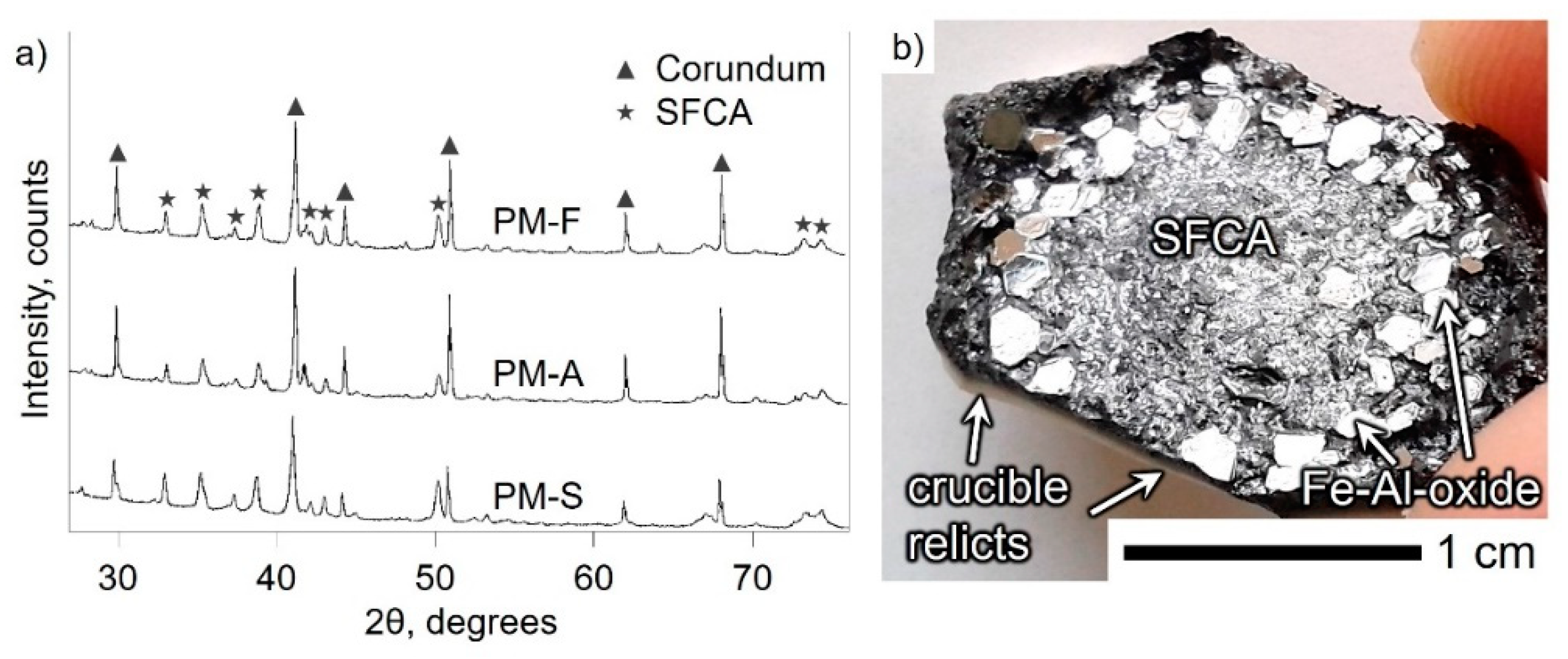
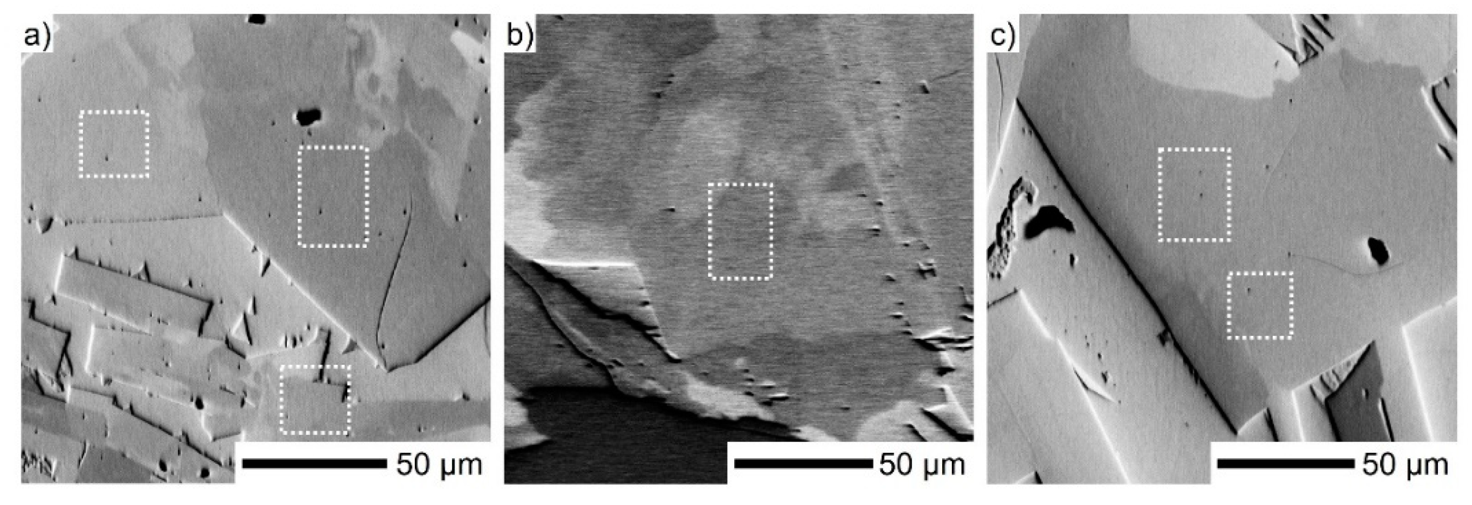
3.1. Mineralogical Characterization

In all experiments, well-developed SFCA crystals without inclusions from the raw materials and SFCA-I were synthesized, which indicates their crystallization from the melt (Figure 2a,b). In sample PM-A, large iron-aluminum oxide grains were observed in addition (Figure 2c), which will be described below and discussed in Section 4.1.
In the diffractogram, the SFCA phase is easily recognized together with corundum Al2O3, which does not pertain to the synthesis product (Figure 3a). During heat treatment, the melt produced from fusion of the pellet penetrated into the corundum crucible and welded the sample material to the crucible (Figure 3b). As the separation after the experiment was impossible, both materials were detected in the XRD measurements.
The chemical compositions of the calcium ferrites are presented in Table 4. Based on their Al2O3 content the calcium ferrites could be classified as SFCA-II, which is defined as a high-Al phase, rather than SFCA [7]. Some important diffraction peaks, which would be diagnostic for SFCA-II, are missing, thus the successful crystallization of SFCA only is confirmed. Moreover, the contents of CaO, SiO2, and MgO are in accord with the usual chemical composition of SFCA from iron ore sinters.
The Al-oxide crucible served as an alumina source and had a strong influence on the chemical composition of the ferrites. As expected, the SFCA crystals in the PM-F sample show the highest Fe-content, but their composition deviates substantially from the composition of the starting mixture; SFCA in PM-S sample accumulated more SiO2 than that in the PM-F sample, but still less SiO2 than the ferrites in PM-A. Surprisingly, the SFCA crystals in PM-A showed the lowest Al2O3 content, even though the Al2O3 content was highest in the starting mixture (Table 4). In PM-A, another alumina-rich, refractory phase, an iron-aluminum oxide (53.96 wt.% Al2O3, 35.47 wt.% FeO/Fe2O3, 7.44 wt.% CaO, 1.01 wt.% SiO2 and 0.39 wt.% MgO) formed in addition to SFCA, which was observable at the pellet periphery close to the side walls of the crucible.
Furthermore, the composition of the glassy silicate phase differed between the samples (Table 4). In PM-S, the glass showed the highest basicity and the highest CaO content of all samples. In sample PM-A, the sample with the highest Al2O3 content, the alumina was mainly distributed among three Al-rich phases including SFCA, iron-aluminum oxide, and the glass. As can be seen in Table 4, minor impurities such as alkali oxides originating from the iron ore migrated primarily into the glass phase. Na2O in particular was present in appreciable amounts. The highest Na2O concentrations were observed in PM-A. Although Na2O, K2O, and BaO have been recognized as possible components of SFCA [3], their presence could not be confirmed in the ferrites of our samples.
In the structure of SFCA the octahedral and tetrahedral cation sites (Y and Z in X2Y6Z6O20) are occupied by Ca2+, Mg2+, Fe2+, Fe3+, Al3+, and Fe3+, Si4+, Al3+, respectively. As the EPMA results do not allow these positions to be distinguished, the chemical formulae of the three ferrites were calculated with the Y and Z sites in accordance with the preferential occupancy of Al3+ in the tetrahedral positions [3,33]:
PM-F: Ca2(Ca0.19Mg0.20Fe2+0.48Fe3+5.13)(Fe3+0.60Si0.86Al4.53)O20;
PM-A: Ca2(Ca0.26Mg0.25Fe2+0.68Fe3+4.80)(Fe3+0.36Si1.19Al4.45)O20;
PM-S: Ca2(Ca0.28Mg0.25Fe2+0.37Fe3+5.10)(Fe3+0.35Si0.90Al4.75)O20.
When establishing the chemical formula of the ferrites, Fe2+/Fe3+ was calculated from the condition of charge balance using the overall formula M14O20.
The SFCA crystals show considerable compositional heterogeneity. Some element co-variation trends are shown in Figure 4 (expressed in atoms per formula unit–a.p.f.u.). In the SFCA crystals of the PM-F and PM-S samples, the Al3+ and Fe3+ contents are negatively correlated. In contrast, the SFCA crystals in PM-A show variation only of Fe3+, while the Al3+ content remains largely constant. The compositions of the SFCA crystals in PM-S only show minor variations in the (Ca2+ + Fe2+ + Si4+) and (Fe3+ + Al3+) contents; in PM-F they also show a small variation, where (Ca2+ + Fe2+ + Si4+) and (Fe3+ + Al3+) are negatively correlated. Finally, the SFCA crystals in PM-A show a comparatively large variation with similar negative correlation between (Ca2+ + Fe2+ + Si4+) and (Fe3+ + Al3+).

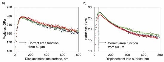
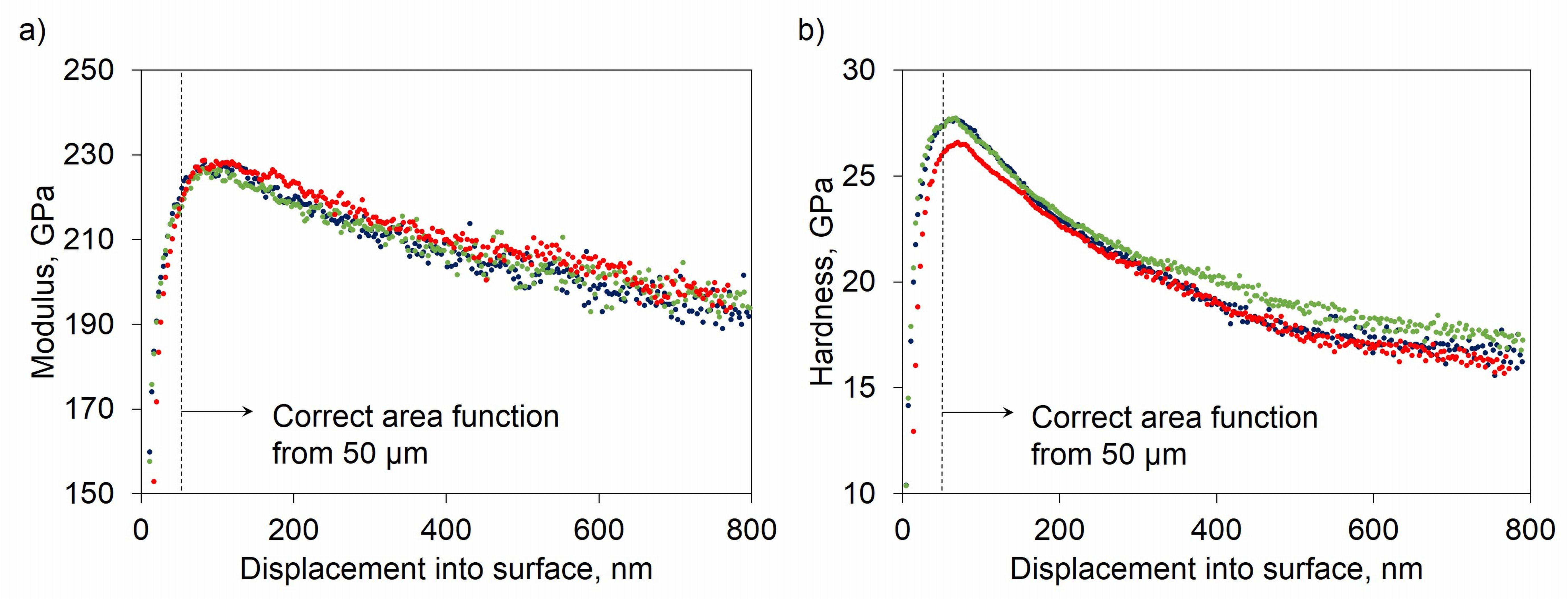
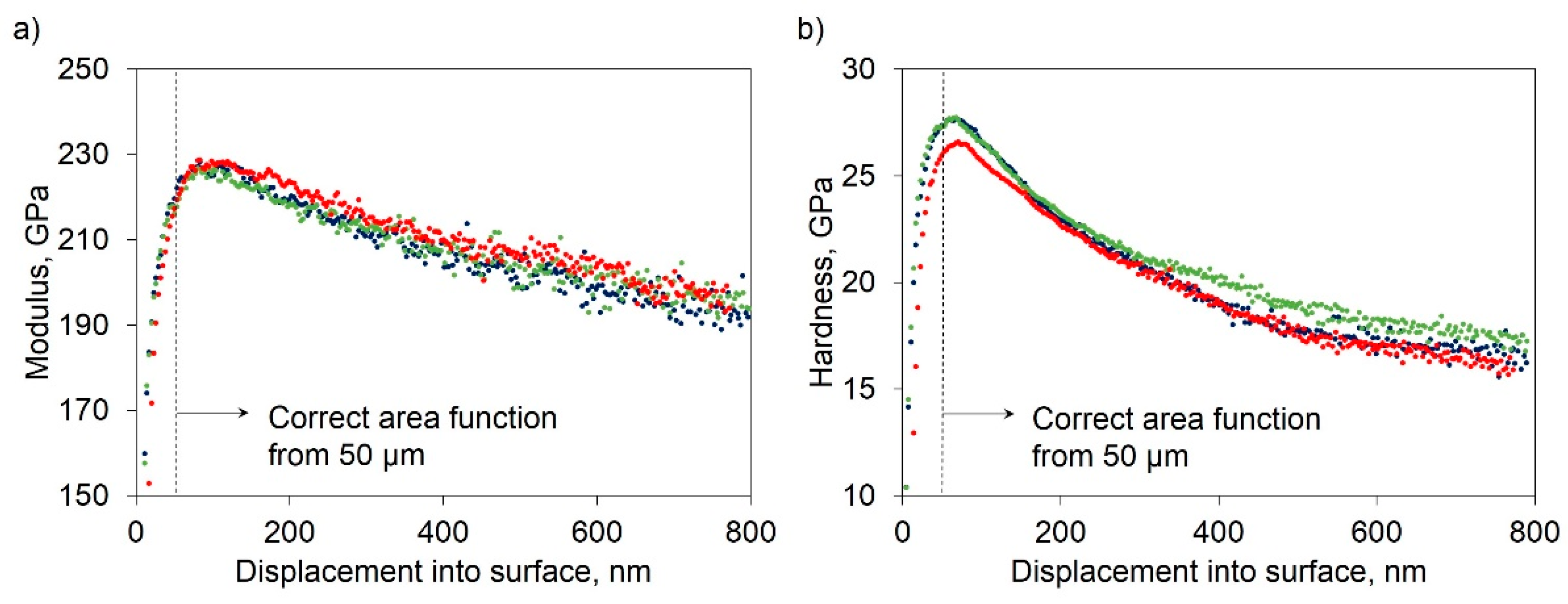
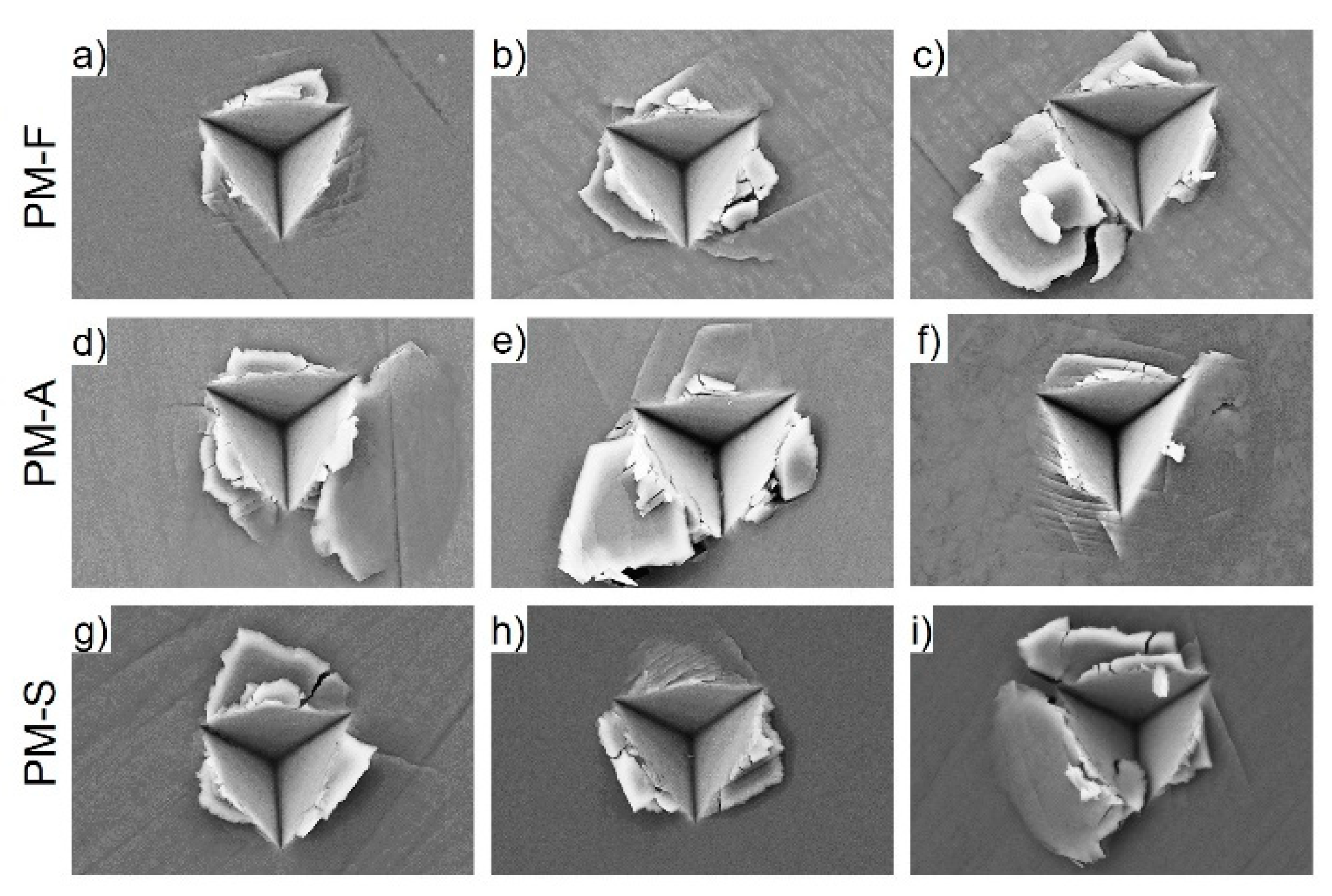
3.2. Mechanical Characterization

For nanoindentation testing, large SFCA crystals with a smooth surface were chosen. On each selected grain, 9 or 12 indents were carried out depending on the crystal size. In all three samples (PM-F, PM-A, and PM-S) at least three different crystals were tested.
Because the measurement results were very similar for all samples, they will be further presented mostly based on one representative sample: PM-F.
Typical load-displacement curves recorded from SFCA crystals in PM-F are presented in Figure 5a. The three colors of the curves represent sets of measurements done on three different SFCA crystals. The curves have almost identical shapes. The observed small differences are probably related to the varying crystallographic orientations of the tested SFCA crystals. Some pop-in events breaking the curves (Figure 5b,c) will be discussed below.
Nearly identical shapes were also observed for the sets of colored curves representing the elastic modulus and the indentation hardness of the three different crystals tested in PM-F (Figure 6). Here, it is important to note that there were several factors that had to be taken into account in order to evaluate the hardness and elastic modulus of SFCA grains using Equations (1)–(3). During cube-corner indentation, which tends to induce large deformation and fracture in materials due to its sharp tip geometry, cracking and pile-ups occurred around the indents (see Figure 8 below). Both of these processes made the data evaluation more difficult since Equations (1)–(3) do not consider them. The pop-ins on the loading curves of SFCA grains in Figure 5 suggest that crack formation occurred during loading rather than unloading, in agreement with the results for other brittle materials reported in the literature [34,35]. The presence of cracks reduces the modulus of the materials due to their decreased stiffness according to Equation (3), while the calculated modulus overestimates its real value during the occurrence of pile-ups due to the extra surfaces formed around the indent [36]. Thus, the calculated elastic modulus and hardness plots in Figure 6 are influenced by two main factors, of which cracking seems to be the dominant one, reducing slightly the modulus of SFCA from ~230 to ~200 GPa (13% decrease). Regarding hardness, the decrease is more pronounced, which is attributed to the so-called indentation size effect (ISE) rather than simply to cracking. This is a well-known phenomenon for many materials, where the hardness decreases with increasing load/indentation depth. Several theories have been proposed to explain this ISE, the most popular of which is probably the gradient plasticity theory, wherein geometrically necessary dislocations (GNDs) are generated under the indenter due to strain gradients [37,38].
Regarding the fact even a brand-new cube-corner indenter is not infinitely sharp at its tip but has a rounded end, the plastic deformation and subsequent pile-ups and cracking develop gradually in SFCA grains during indentation. For this reason, the elastic modulus and hardness calculated with Equations (1)–(3) are assumed to approximate the real values of SFCA grains at small depths (above the calibration limit of 50 nm), taken as the average of values from the range of 50–100 nm in Figure 6. Surface effects are considered to be negligible above 50 nm, as confirmed by the visible orientation contrast in the fore-scattered electron (FSE) images in Figure 7, which have an information depth ~50 nm of material.
Differences in the crystallographic orientations of the tested SFCA grains, which are single crystals, are clearly visible in the FSE image shown in Figure 7a, where the different gray shades indicate different crystallographic orientations. The three groups of curves from Figure 5; Figure 6 (i.e., blue, red, and green) correspond to the indents made inside the squares and rectangles marked on Figure 7a. All three sets of indents were performed on differently-oriented crystals. It is very likely that the differences between the curves are related to the differences in crystallographic orientation.
The elastic modulus and indentation hardness are quite consistent and only show minor variations within sample PM-F: the modulus and hardness values obtained for the depth range 50–100 nm were calculated as 226.5, 223.9, and 223.7 GPa, as well as 26.1, 27.4, and 27.1 GPa, respectively, with standard deviations of ~5–7 GPa and ~1.2 GPa. Similar behavior was observed in the other two samples and some of the indentation positions in PM-A and PM-S are shown in Figure 7b,c. Note that the surface of the samples was re-polished and therefore the marks in Figure 7 correspond to the surface area where nanoindentation was performed (i.e., no indents were made on the SFCA-glass interface). On the other hand, through the removal of a thin surface layer the indents were removed as well and no inclusions such as those in Figure 2b appeared, which confirmed that the indents were performed only in pure SFCA crystals.
Further SEM examination of the indents did not reveal any radial cracks emanating from the corners of the indents, which would be typical for brittle material behavior (see Figure 8). Instead of cracks, slip lines, and chipped parts, sometimes accumulated in several layers are visible at the perimeters of the indents. When a crack was initiated and a chipped part was formed splitting off from the surface (Figure 8c,e), a pop-in event appeared on the loading part of the indentation curve. Such an event is clearly visible on the red curve in Figure 5c. This indicates that pop-in events on the load-displacement curves are related to plastic deformation and fracture, resulting in pile-ups, cracking, and partial or total chipping around the indents, similar to the deformations found in other works reporting on brittle materials [34,35]. This deformation behavior and the corresponding patterns are significantly different from the radial cracks emanating from the corners of indents in more brittle materials. As a result, the standard procedures for determining fracture toughness from radial cracks cannot be applied to SFCA crystals [39]. In cases where the chipped parts are still connected with the rest of the material (Figure 8d,f,i), only slight breaks appear on the loading part of the indentation curves, as shown on the F-h curve in Figure 5b. In addition to cracking, pile-ups around the indents are also visible in Figure 8. This suggests that the elastic modulus and hardness measurements overestimate their real values at greater depths due to the extra surface of pile-ups, which is not considered in Equations (1)–(3). To circumvent the complications arising from pile-ups, the mechanical properties were evaluated from the shallow indentation depth of 50–100 nm, where the effect of possible pile-ups is considered to be negligible, as described earlier.
Because the crystallographic orientation has only minor influence on the measured values of modulus and hardness, the data for the individual crystals were averaged over the entire sample. Statistical evaluation of the elastic modulus and hardness for each sample calculated for the indentation depth range of 50–100 nm is shown in Table 5. The averaged values of both modulus and hardness for the three tested phases do not differ significantly. This is in accordance with the similar chemical composition of these SFCA phases. The mean elastic modulus and the indentation hardness values for alumina-rich SFCA in the form of well-defined homogeneous grains are E = 225.1 ± 8.1 GPa and H = 27.2 ± 1.9 GPa, respectively.

4. Discussion

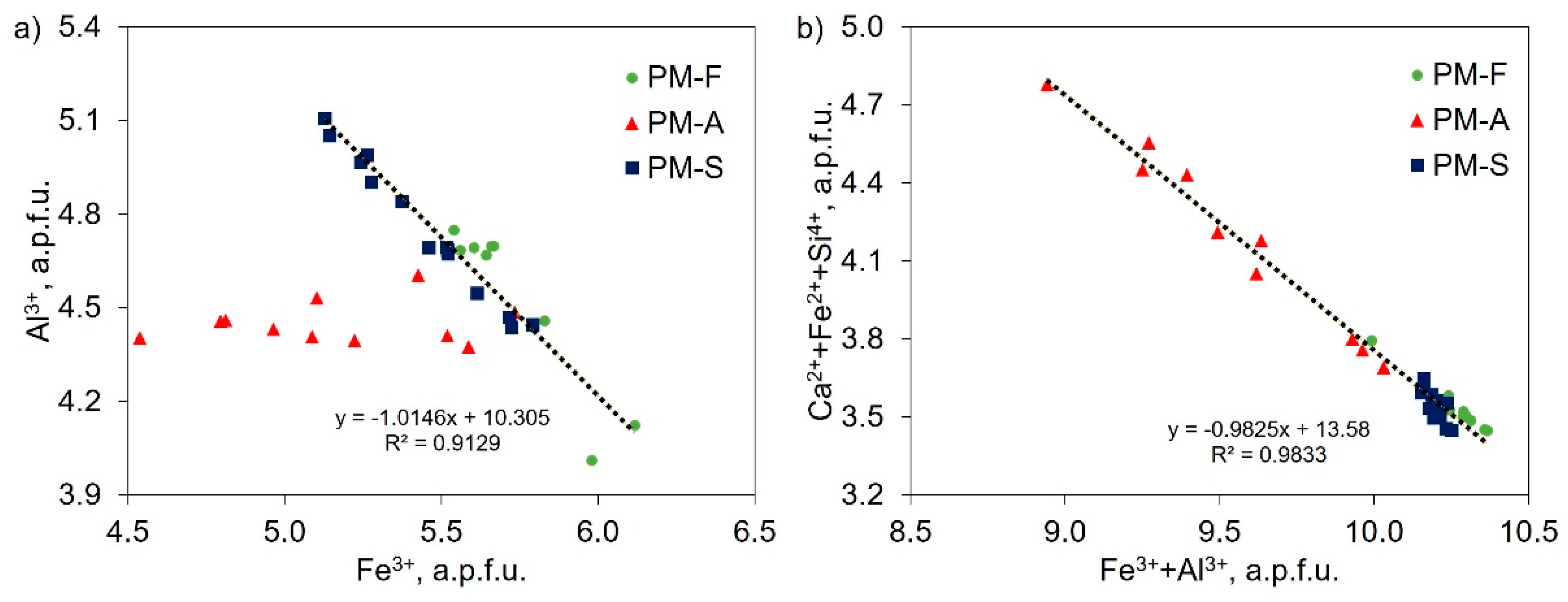
4.1. Chemical Composition of SFCA

Similarly to the processes occurring in the adhering layer of a sinter granule, two stages need to be considered with respect to the synthesis of ferrites. During the early experimental stages, the particles of the pressed starting mixture remained in solid state. Reactions between the particles were thus confined to small volumes next to the grain contacts. Due to slow diffusion of alumina in the solid state, the contribution of alumina from the crucible was negligible. As a consequence, binary and ternary calcium ferrites were formed, which served as the precursor phases for SFCA formation with chemical compositions probably close to the composition of the starting-mixtures [40]. When the peak temperatures (1450 and 1500 °C) were reached, incongruent melting occurred. During this stage, substantial amounts of alumina were incorporated into the melt through reaction of the melt with the Al-oxide crucible. This stage corresponds to primary melt penetration in the granule nuclei of iron ore sinters. The increased alumina content stabilized SFCA at higher temperatures and stimulated crystallization of SFCA from the melt. The SFCA crystals growing during the melt stage have highly-elevated Al content, governed by the equilibrium partitioning of Al2O3 between the ferrites and the melt. This interpretation is corroborated by the microstructures, which indicate that the SFCA crystals grew from the melt.
The prominent negative correlation between Fe3+ and Al3+ in the SFCA crystals of samples PM-F and PM-A indicates that the substitution of Al3+ for Fe3+ proceeded as a consequence of the alumina supply from the crucible (Figure 4a). This progressive substitution led to supersaturation of SFCA with respect to Fe2O3; consequently, Fe-oxides were segregated from the SFCA giving rise to fine-grained iron oxide precipitates within the SFCA crystals (Figure 2b). The comparatively low Al content of the SFCA crystals in PM-A suggests that an additional Al-Fe-oxide phase had grown earlier than the SFCA crystals, so that the melt was already substantially depleted of the Al component when the latter started to grow. The negative correlation between (Ca2+ + Fe2+ + Si4+) and (Fe3+ + Al3+), observed only in PM-A indicates that during their growth the availability of Al3+ and Fe3+ was limited and forced the growing crystals to replace the trivalent cations with a combination of divalent cations and silicon. This is very likely due to the depletion of Al3+ and Fe3+ in the melt caused by early crystallization of the Fe-Al oxide phase. The coupled substitution 2(Fe3+, Al3+) ↔ (Ca2+, Fe2+) + Si4+ was proposed earlier by Patrick and Pownceby [8], who investigated the solid solution limits of elements within SFCA.
To explain the rather similar chemical composition of SFCA despite the contrasting starting mixtures, other phases in equilibrium with SFCA should be considered as well. Due to their low abundance, these phases could only be observed under the microscope and not by means of XRD. In all of these experiments, an unlimited source of alumina was available in the form of the crucible. In the case of the PM-F sample, the higher iron content in the mixture caused elevated Fe2O3 content in the ferrites, but the other components appear to have been buffered by their coexistence with the melt and iron oxides. In PM-S, the high CaO and SiO2 contents were primarily accommodated in the melt, which is now represented by the silicate glass. Sample PM-A is a specific case, because an iron-aluminum oxide formed early during the experiments, which strongly incorporated Al3+ and Fe3+ into its structure. This led to depletion of the melt with respect to Al2O3 and Fe2O3, leaving relatively little of these components available during the growth of SFCA. However, the overall fraction of the Al-rich phase was too low to create observable peaks in XRD. This iron-aluminum oxide had a composition of (Fe2+, Ca2+, Mg2+) (Al3+, Si4+)2O4, very close to the composition of hercynite, albeit with lower MgO and higher CaO contents. Another conceivable phase was Al2Fe2O6, though the analyzed Al2O3 content was too high. Moreover, Al2Fe2O6 is not stable at room temperature, so as the system cooled down very slowly, preservation of this phase is unlikely. Interestingly, this phase typically crystallized close to the crucible walls suggesting that in real sinter granules spinel should be expected to occur near the alumina-rich nuclei within the granule.
Although these ferrites were synthesized in air, the presence of magnetite in the samples indicates that the atmosphere was not sufficiently oxidizing to convert all magnetite to hematite. Moreover, some Fe2+ was incorporated into the SFCA structure. The resulting Fe2+/(Fe2+ + Fe3+) ratio was 0.08, 0.12, and 0.06 for the SFCA in PM-F, PM-A, and PM-S, respectively. This is in line with the trend in the overall Fe2+/(Fe2+ + Fe3+) ratio within the samples as determined by chemical analysis: 0.12, 0.16 and 0.12 for PM-F, PM-A, and PM-S, respectively.

4.2. Factors Influencing the Mechanical Properties

Despite the different starting mixtures with different compositions and despite the use of different raw materials, SFCA crystals with rather similar chemical compositions were produced. This indicates that the conditions and the synthesis route rather than the starting materials determine the characteristics of the synthesis products. Similar values for hardness and modulus reveal that the mechanical properties of the SFCA crystals are largely independent of the raw materials.
Testing differently-oriented crystals within one sample yielded only minute variations in measured modulus and hardness, suggesting that on the scale of these experiments the crystallographic orientation of the different crystals only had a minor effect on the measured mechanical properties of the SFCA crystals.
Compared with the results from earlier studies [18,19,20,21,22], this work provides a new view on the determination of mechanical properties. The obtained data are difficult to compare with classical Vickers microhardness, but on the other hand, the values were obtained with an accurate method allowing for rigorous comparison with the future examination of mechanical properties of sinter phases.

4.3. Correlation with Industrial Sintering

In this study, the examination of SFCA properties was narrowly focused on specific high-Al2O3 sintering. This is relevant for sinter plants processing ores with high-alumina-based gangue. However, besides the increasing gangue content in iron ores, there is also a tendency to use richer ores for sintering. Thus, future work under other conditions is essential in order to investigate the properties of more compositional models of the SFCA phase.

5. Conclusions

The effect of alumina-based nuclei within sinter granules on the mineralogy and mechanical properties of SFCA formed in three chemically different adhering layers was investigated. The scenarios were simulated by heating three different powders in aluminum oxide crucibles, which were taken as a proxy for the alumina nuclei. The mechanical properties of the synthesized SFCA crystals were tested by means of nanoindentation using a cube corner indenter and the elastic modulus and hardness of the different SFCA crystals were determined. After heating and subsequent cooling of various different mixtures of raw ores with differing gangue minerals in alumina crucibles, somewhat similar SFCA phases rich in Al2O3 with only slight variations in chemical composition were produced. The compositional and mechanical characteristics of the crystals seem to be related to the saturation of the phases with alumina and to the cooling procedure. The ferrites in all samples showed quite similar mechanical properties, irrespective of their crystallographic orientations. The crystallographic orientation seems therefore to have only minor influence on the mechanical properties of SFCA crystals. The average elastic modulus and hardness of the SFCA crystals were obtained as E = 225.1 ± 8.1 GPa and H = 27.2 ± 1.9 GPa, respectively. Crystal-plastic behavior of SFCA during nanoindentation is reflected in the slip lines and chipped parts around the indents. It is inferred that in the presence of alumina-rich nuclei within sinter granules the properties of newly-formed SFCA are determined by Al2O3 from the alumina-rich nucleus regardless of the chemical composition of the fine ore particles in the adhering layer.

Author Contributions

Conceptualization, R.M.; Investigation, R.M. and T.C.; Methodology, R.M., T.C. and G.H.; Resources, M.F. and J.D.; Supervision, M.F., J.D. and R.A.; Writing—Original Draft, R.M. and T.C.; Writing—Review & Editing, G.H. and R.A.

Funding

This research was funded by the Slovak Research and Development Agency (APVV), grant number 16-0513. This work was realized within the frame of the project „Research Centre of Advanced Materials and Technologies for Recent and Future Applications “PROMATECH” ITMS: 26220220186, which is supported by the Operational Program “Research and Development” financed through European Regional Development Fund.

Acknowledgments

R.M. gratefully acknowledges the Ernst Mach Grant provided by Action Austria-Slovakia. The authors further wish to thank Róbert Findorák (TU Košice) for heating of the samples, Dagmar Jakubéczyová (SAS Košice), Ilka Wünsche and Roman Schuster (both Univ. Wien) for sample preparation and Theodoros Ntaflos (Univ. Wien) for EPMA analyses.

Conflicts of Interest

The authors declare no conflict of interest.

References

  1. Kalenga, M.K.; Garbers-Craig, A.M. Investigation into how the magnesia, silica, and alumina contents of iron ore sinter influence its mineralogy and properties. J. South. Afr. Inst. Min. Metall. 2010, 110, 447–456. [Google Scholar]
  2. Mežibrický, R.; Fröhlichová, M. Comparison of iron ore sinter mineralogy quantification. Acta Metall. Slov. 2017, 23, 283–289. [Google Scholar] [CrossRef]
  3. Da Costa, E.; Coheur, J.P. Association of calcium ferrites in iron ore sinter with aenigmatites. Ironmak. Steelmak. 1995, 22, 223–226. [Google Scholar]
  4. Hapugoda, S.; Lu, L.; Donskoi, E.; Manuel, J. Mineralogical quantification of iron ore sinter. Miner. Process. Extr. Metall. 2016, 125, 156–164. [Google Scholar] [CrossRef]
  5. Sugiyama, K.; Monkawa, A.; Sugiyama, T. Crystal structure of the SFCAM phase Ca2(Ca,Fe,Mg,Al)6(Fe,Al,Si)6O20. ISIJ Int. 2005, 45, 560–568. [Google Scholar] [CrossRef]
  6. Mumme, W.G.; Clout, J.M.F.; Gable, R.W. The crystal structure of SFCA-I, Ca3.18Fe3+14.66Al1.34Fe2+0.82O28, a homologue of the aenigmatite structure type, and new crystal structure refinements of ß-CFF, Ca2.99Fe3+14.30Fe2+0.55O25 and Mg-free SFCA, Ca2.45Fe3+9.04Al1.74Fe2+0.16Si0.6O20. N. Jb. Mineral. Abh. 1998, 173, 93–117. [Google Scholar]
  7. Mumme, W.G. The crystal structure of SFCA-II, Ca5.1Al9.3Fe3+18.7Fe2+0.9O48 a new homologue of the aenigmatite structure-type, and structure refinement of SFCA-type, Ca2Al5Fe7O20. Implications for the nature of the “ternary-phase solid-solution” previously reported in the CaO-Al2O3-iron oxide system. N. Jb. Mineral. Abh. (J. Mineral. Geochem.) 2003, 178, 307–335. [Google Scholar]
  8. Patrick, T.R.; Pownceby, M.I. Stability of silico-ferrite of calcium and aluminum (SFCA) in air-solid solution limits between 1240° C and 1390° C and phase relationships within the Fe2O3-CaO-Al2O3-SiO2 (FCAS) system. Metall. Mater. Trans. B 2002, 33, 79–89. [Google Scholar] [CrossRef]
  9. Xiang, S.; Lv, X.; Yu, B.; Xu, J.; Yin, J. The Dissolution Kinetics of Al2O3 into Molten CaO-Al2O3-Fe2O3 Slag. Metall. Mater. Trans. B 2014, 45, 2106–2117. [Google Scholar] [CrossRef]
  10. Lu, L.; Holmes, R.J.; Manuel, J.R. Effects of alumina on sintering performance of hematite iron ores. ISIJ Int. 2007, 47, 349–358. [Google Scholar] [CrossRef]
  11. Pimenta, H.P.; Seshadri, V. Influence of Al2O3 and TiO2 Degradation Behaviour of Sinter and Hematite at Low Temperatures on Reduction. Ironmak. Steelmak. 2002, 29, 175–179. [Google Scholar] [CrossRef]
  12. Umadevi, T.; Mahapatra, P.C.; Prabhu, M. Influence of MgO addition on microstructure and properties of low and high silica iron ore sinter. Miner. Process. Extr. Metall. 2013, 122, 238–248. [Google Scholar] [CrossRef]
  13. Mitra, D.; Sinha, S. Five decades of sinter-making at TATA Steel, a continuous improvement journey. In Proceedings of the 8th ICSTI Conference Proceedings, Vienna, Austria, 25–28 September 2018; pp. 262–267. [Google Scholar]
  14. Okazaki, J.; Higuchi, K. Marra Mamba ore, its mineralogical properties and evaluation for utilization. ISIJ Int. 2005, 45, 427–435. [Google Scholar] [CrossRef]
  15. De Magalhães, M.S.; Brandão, P.R.G.; Tavares, R.P. Types of goethite from Quadrilátero Ferrífero’s iron ores and their implications in the sintering process. Miner. Process. Extr. Metall. 2007, 116, 54–64. [Google Scholar] [CrossRef]
  16. Sinha, M.; Nistala, S.H.; Chandra, S.; Mankhand, T.R. Mineralogy of Iron Ores of Different Alumina Levels from Singhbhum Belt and Their Implication on Sintering Process. J. Miner. Mater. Charact. Eng. 2015, 3, 180–193. [Google Scholar] [CrossRef]
  17. Haga, T.; Ohshio, A.; Nakamura, K.; Kozono, T.; Uekawa, K. Control Technique of the Melting Reaction in Sintering Process by the Fine Part Selective Granulation of Clayish Iron Ores. ISIJ Int. 1997, 83, 103–108. [Google Scholar]
  18. Sakamoto, N.; Fukuyo, H.; Iwata, Y.; Miyashita, T. Mineralogical Study on Degradation of Sinter Structure at Low Temperature Reduction. Tetsu-to-Hagané 1984, 70, 512–519. [Google Scholar] [CrossRef] [Green Version]
  19. Shigaki, I.; Sawada, M.; Gennai, N. Increase in Low-temperature Reduction of Iron Ore Sinter due to Hematite-alumina Solid Solution and Columnar Calcium Ferite. Trans. Iron Steel Inst. Jpn. 1986, 26, 503–511. [Google Scholar] [CrossRef]
  20. Ying, Z.W.; Jiang, M.F.; Xu, L.X. Effects of mineral composition and microstructure on crack resistance of sintered ore. J. Iron Steel Res., Int. 2006, 13, 9–12. [Google Scholar] [CrossRef]
  21. Sinha, M.; Nistala, S.H.; Chandra, S.; Mankhand, T.R.; Ghose, A.K. Correlating mechanical properties of sinter phases with their chemistry and its effect on sinter quality. Ironmak. Steelmak. 2017, 44, 100–107. [Google Scholar] [CrossRef]
  22. Yang, D.; Wang, W.; Xu, R.; Li, J.; Song, M. Effect of SiO2 on the Mechanical Property and Reduction of Calcium Ferrite. Metals 2019, 9, 152. [Google Scholar] [CrossRef]
  23. De Magalhães, M.S.; Brandão, P.R.G. Microstructures of industrial sinters from Quadrilatero Ferrifero’s iron ores, Minas Gerais State, Brazil. Miner. Eng. 2003, 16, 1251–1256. [Google Scholar] [CrossRef]
  24. Li, L.; Liu, J.; Wu, X.; Ren, X.; Bing, W.; Wu, L. Influence of Al2O3 on equilibrium sinter phase in N2 atmosphere. ISIJ Int. 2010, 50, 327–329. [Google Scholar] [CrossRef]
  25. Mežibrický, R.; Fröhlichová, M. Mineral phases in iron ore sinters produced with oak sawdust substitute fuel. J. Min. Metall. Sect. B-Metall. 2018, 54, 9–20. [Google Scholar] [CrossRef] [Green Version]
  26. Webster, N.A.S.; Pownceby, M.I.; Madsen, I.C.; Kimpton, J.A. Silico-ferrite of calcium and aluminum (SFCA) iron ore sinter bonding phases: New insights into their formation during heating and cooling. Metall. Mater. Trans. B 2012, 43, 1344–1357. [Google Scholar] [CrossRef]
  27. Mežibrický, R.; Fröhlichová, M. Silico-ferrite of Calcium and Aluminum Characterization by Crystal Morphology in Iron Ore Sinter Microstructure. ISIJ Int. 2016, 56, 1111–1113. [Google Scholar] [CrossRef] [Green Version]
  28. Oliver, W.C.; Pharr, G.M. An improved technique for determining hardness and elastic modulus using load and displacement sensing indentation experiments. J. Mater. Res. 1992, 7, 1564–1583. [Google Scholar] [CrossRef]
  29. Li, X.; Bhushan, B. A review of nanoindentation continuous stiffness measurement technique and its applications. Mater. Charact. 2002, 48, 11–36. [Google Scholar] [CrossRef]
  30. Oliver, W.C.; Pharr, G.M. Measurement of hardness and elastic modulus by instrumented indentation: Advances in understanding and refinements to methodology. J. Mater. Res. 2004, 19, 3–20. [Google Scholar] [CrossRef]
  31. Gercek, H. Poisson’s ratio values for rocks. Int. J. Rock Mech. Min. Sc. 2007, 44, 1–13. [Google Scholar] [CrossRef]
  32. Hamilton, J.D.G.; Hoskins, B.F.; Mumme, W.G.; Borbidge, W.E.; Montague, M.A. The crystal structure and crystal chemistry of Ca2.3Mg0.8Al1.5Si1.1Fe8.3O20 (SFCA): Solid solution limits and selected phase relationships of SFCA in the SiO2 – Fe2O3 – CaO(– Al2O3) system. N. Jb. Mineral. Abh. 1989, 161, 1–26. [Google Scholar]
  33. Murao, R.; Harano, T.; Kimura, M.; Jung, I.H. Thermodynamic Modeling of the SFCA Phase Ca2(Fe,Ca)6(Fe,Al,Si)6O20. ISIJ Int. 2018, 58, 259–266. [Google Scholar] [CrossRef]
  34. Morris, D.J.; Cook, R.F. In situ cube-corner indentation of soda-lime glass and fused silica. J. Am. Ceram. Soc. 2004, 87, 1494–1501. [Google Scholar] [CrossRef]
  35. Cuadrado, N.; Seuba, J.; Casellas, D.; Anglada, M.; Jiménez-Piqué, E. Geometry of nanoindentation cube-corner cracks observed by FIB tomography: Implication for fracture resistance estimation. J. Eur. Ceram. Soc. 2015, 35, 2949–2955. [Google Scholar] [CrossRef]
  36. Csanádi, T.; Németh, D.; Lofaj, F. Mechanical properties of hard W-C coating on steel substrate deduced from nanoindentation and finite element modeling. Exp. Mech. 2017, 57, 1057–1069. [Google Scholar] [CrossRef]
  37. Nabarro, F.R.N.; Shrivastava, S.; Luyckx, S.B. The size effect in microindentation. Philos. Mag. 2006, 86, 4173–4180. [Google Scholar] [CrossRef]
  38. Nix, W.D.; Gao, H. Indentation size effects in crystalline materials: A law for strain gradient plasticity. J. Mech. Phys. Solids. 1998, 46, 411–425. [Google Scholar] [CrossRef]
  39. Lawn, B.R.; Evans, A.G.; Marshall, D.B. Elastic/plastic indentation damage in ceramics: The median/radial crack system. J. Am. Ceram. Soc. 1980, 63, 574–581. [Google Scholar] [CrossRef]
  40. Webster, N.A.S.; O’dea, D.P.; Ellis, B.G.; Pownceby, M.I. Effects of gibbsite, kaolinite and Al-rich goethite as alumina sources on silico-ferrite of calcium and aluminium (SFCA) and SFCA-I iron ore sinter bonding phase formation. ISIJ Int. 2017, 57, 41–47. [Google Scholar] [CrossRef]
Figure 1. Schematic drawing of sinter granule with alumina-rich nuclei.
Metals 09 00906 g001
Figure 2. Reflected light micrographs of the samples: (a) SFCA prisms within sample PM-F, (b) SFCA crystals with iron oxide inclusions (white) in PM-A, (c) iron-aluminum oxide grains within sample PM-A.
Metals 09 00906 g002
Figure 3. (a) Powder diffractograms of the synthesis products PM-F, PM-A, and PM-S; (b) detail of the PM-A sample with the crucible rest.
Metals 09 00906 g003
Figure 4. Element covariation diagrams for (a) Al3+ vs. Fe3+ and (b) Ca2++Fe2++Si4+ vs. Fe3++Al3+.
Metals 09 00906 g004
Figure 5. (a) Indentation curves of the SFCA crystals tested in sample PM-F, (b) detail of a slight pop-in event, and (c) detail of a sharp pop-in event.
Metals 09 00906 g005
Figure 6. Measured curves of (a) modulus and (b) nanoindentation hardness of the SFCA crystals in sample PM-F.
Metals 09 00906 g006
Figure 7. Forescattered electron orientation contrast images of the domains where nanoindentation was applied: (a) PM-F, (b) PM-A, and (c) PM-S. Squares and rectangles mark the position of 9 and 12 indents, respectively.
Metals 09 00906 g007
Figure 8. Secondary electron images of the indents made on SFCA crystals: PM-F: (a), (b), and (c); PM-A (d), (e), and (f); PM-S: (g), (h), and (i). Width of each image is 5.405 µm.
Metals 09 00906 g008
Table 1. Chemical composition of the raw materials, dried, wt.%.
MaterialFetotFeOFe2O3CaOSiO2Al2O3MgO
Carajás ore68.740.2692.860.131.310.980.25
Hematite pellets65.780.2693.761.803.720.210.22
Krivbass ore62.720.6388.990.237.821.650.24
Zaporozhskiy ore62.411.1587.960.698.541.090.32
Sukha Balka ore61.940.3088.220.1010.280.770.10
SB + 8 mm ore *48.410.0069.220.0717.400.750.73
limestone **NANANA46.372.511.304.28
* Sukha Balka + 8 mm fraction; ** loss on ignition 42.45 wt.%; NA: not analyzed.
Table 2. Powder mixing ratio, wt.%. PM-F: an iron-rich mixture; PM-A: a high-alumina mixture (PM-A); PM-S: a high-silica mixture.
MixtureCarajásHematite PelletsKrivbassZaporozhskiySukha BalkaSB+8Al2O3Lime-Stone
PM-F529151015--26
PM-A1115201510-425
PM-S--1625156-38
Table 3. Predicted chemical composition of the powder mixtures, wt.%.
MixtureFetotFeOFe2O3CaOSiO2Al2O3MgOCaO/SiO2
PM-F52.930.3875.2614.286.031.031.432.37
PM-A50.390.4471.5513.475.825.591.382.31
PM-S45.110.5263.9321.288.261.422.152.58
Table 4. Electron Probe Microanalysis (EPMA) of the SFCA crystals and glass phase within samples with standard deviations for ~10 point analyses in the parentheses, wt.%.
SFCAFe2O3CaOSiO2Al2O3MgOTiO2MnOTotal
PM-F54.40 (1.45)13.49 (0.13)5.70 (0.33)25.36 (1.71)0.86 (0.07)0.01 (0.02)0.03 (0.01)99.85 (0.32)
PM-A50.51 (1.91)13.70 (0.80)7.74 (1.30)24.57 (0.39)1.09 (0.23)0.02 (0.02)0.06 (0.01)97.69 (0.24)
PM-S51.75 (1.40)14.23 (0.22)6.01 (0.09)26.99 (1.55)1.14 (0.19)0.02 (0.01)0.04 (0.01)100.18 (0.23)
GlassCaOSiO2Al2O3FeOMgONa2OK2OTiO2MnOBaOTotal
PM-F34.7738.8316.226.750.001.580.260.130.010.0798.61
PM-A28.0234.5126.636.170.003.580.260.190.030.0599.45
PM-S40.0633.1317.977.350.020.870.080.120.010.0099.60
Table 5. Averaged results of the measurements.
SampleAverage Composition of SFCAModulus, GPaHardness, GPa
avgstdvavgstdv
PM-FCa2(Ca0.19Mg0.20Fe2+0.48Fe3+5.13)(Fe3+0.60Si0.86Al4.53)O20224.76.126.91.4
PM-ACa2(Ca0.26Mg0.25Fe2+0.68Fe3+4.80)(Fe3+0.36Si1.19Al4.45)O20221.311.527.22.9
PM-SCa2(Ca0.28Mg0.25Fe2+0.37Fe3+5.10)(Fe3+0.35Si0.90Al4.75)O20227.95.027.41.2
Average225.18.127.21.9
Statistic for ~30 measurements per sample.

