Article

Research on Lightweight Design and Indirect Hot Stamping Process of the New Ultra-High Strength Steel Seat Bracket

1
Key Laboratory of Automobile Materials, Department of Materials Science and Engineering, Jilin University, Changchun 130022, China
2
Roll Forging Research Institute, Jilin University, Changchun 130022, China
*
Author to whom correspondence should be addressed.
Metals 2019, 9(8), 833; https://doi.org/10.3390/met9080833
Submission received: 3 July 2019 / Revised: 24 July 2019 / Accepted: 25 July 2019 / Published: 26 July 2019

Abstract

:
Aiming at the need for lightweight requirements of the electric bus components, combined with the performance advantages of the hot stamping ultra-high strength steel, a new type of seat bracket structure is proposed. The new structure was analyzed by finite element method and the variable density topology optimization results. Subsequently, the new seat bracket was manufactured by the indirect hot stamping process. The results showed that the new type of seat bracket can reduce the weight by 17.04% after topology optimization, which achieved the goal of lightweight design of the structure. After indirect hot stamping, the bottom of the seat bracket microstructures were mainly martensite and the ultimate tensile strength was about 1560 MPa, the microhardness was equally distributed at about 513.5 HV. Finally, according to the stiffness check test, the seat bracket satisfied the user requirements.

1. Introduction

The electric bus is becoming more practical today because of its lower pollution and less noise with higher energy efficiency compared to the fuel bus [1,2]. However, how to reduce weight and shorten design cycle are two basic problems that are necessary to be considered during the bus design process. Weight reduction of the bus can save more energy, and improve the efficiency of public transportation. However, the original strength and structural stiffness should not be weakened in the weight reduction design. High stiffness is a requirement for most automobile components (e.g. brackets, car body) in simulation. In this situation, using finite element analysis (FEA) is a more convenient and reasonable way to optimize the structure. So far, many finite element method (FEM) commercial software have the structural optimization module, e.g. the SIMULIA Tosca Structure applied in ABAQUS, ANSYS [3]. Li et al. used an optimization method based on the minimized weight while satisfying all stiffness constraints to redesign the engine cradle [4]. Also, the authors used lightweight material and topology method to optimize the size, the shape of a cross car beam structure [5]. Yildiz et al. proposed different methods to introduce the application of topology optimization in vehicle components [6,7].
For the reduction in weight and improvement of the vehicles crash safety, ultra-high strength steel becomes more extensively used in A/B-pillar, bumper, tunnel, and other anti-collision beams in the automotive industry. According to the references, ultra-high strength steel can reduce the body-in-white structural mass by nearly 30% [8,9,10]. Hot stamping is a principal method for ultra-high strength steel production, which needs a small forming load and gives less springback after quenching [11,12,13]. It can be divided into direct hot stamping and indirect hot stamping. The indirect hot stamping is mainly used to form sheet with complex shapes and the sheet needed to be pre-formed before heating and quenching [14,15,16]. Seo et al. investigated the formability of direct and indirect hot stamping processes under different blank holding forces of ultra-high strength steel [17].
However, this kind of material is rarely used on the electric bus. This paper focused on using ultra-high strength steel on electric bus components. The bus seat, especially the seat bracket, plays an important role among the components of the electric bus and it also effects the comfort and safety of the passengers. Therefore, this paper focused on redesigning the new structure of the seat bracket according to the finite element analysis and topology optimization method. Subsequently, ultra-high strength steel by indirect hot stamping process was used to form the new seat bracket. The reasonable indirect hot stamping parameters were discussed. Then the mechanical behaviors and microstructures of the seat bracket after indirect hot stamping process was analyzed. Finally, to verify the rationality of the design, stiffness experiment was performed on the seat bracket.

2. Finite Element Model and Optimization Analysis

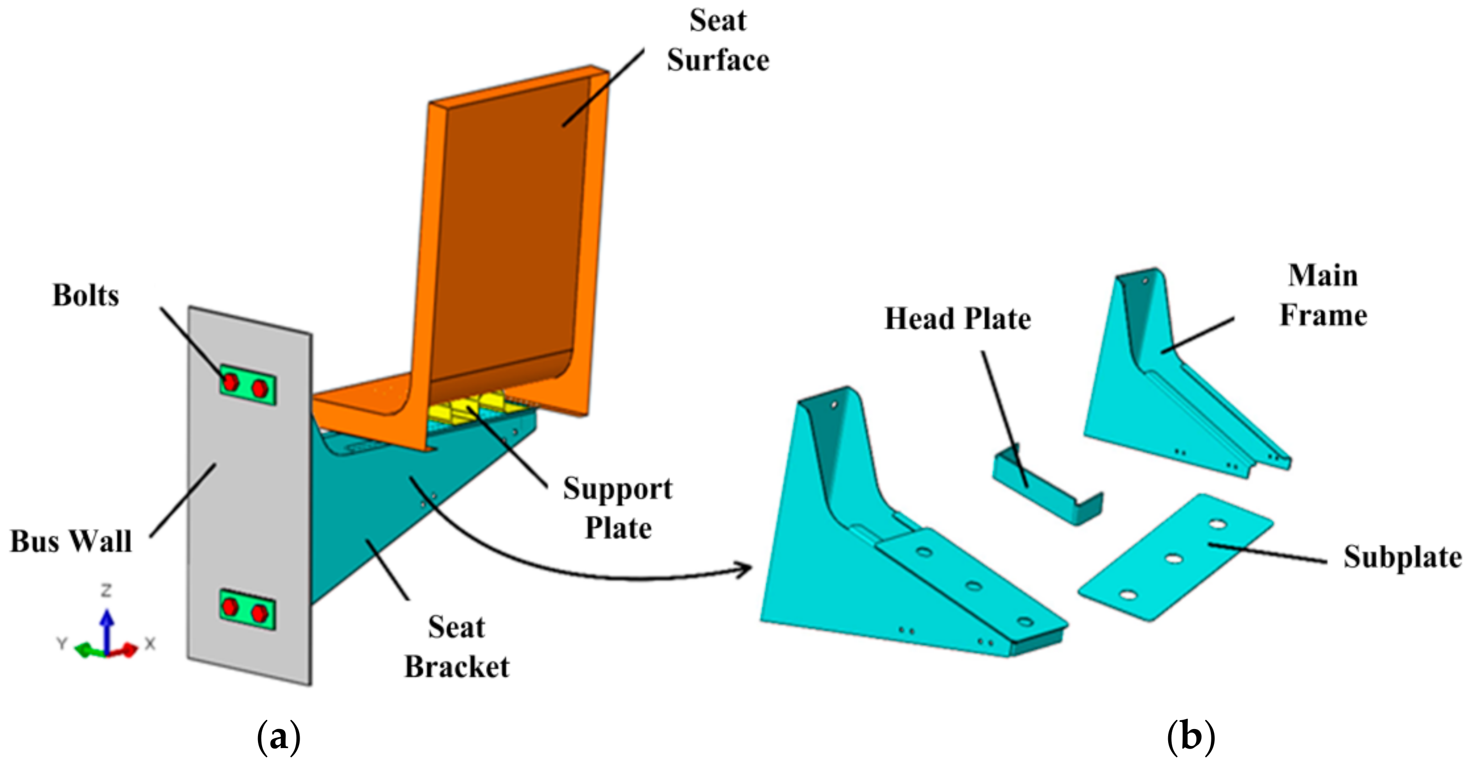
2.1. Finite Element Model

ABAQUS was used to establish the finite element model, as shown in Figure 1. One seat consists of the seat surface, the seat bracket, and the support plate. The initial seat bracket is composed of the main frame, the head plate and the sub-plate, as shown in Figure 1b. The head plate and the sub-plate are welded to the main frame. Then the initial seat bracket is bolted to the electric bus wall. The seat bracket is hanged on the bus wall, thus a high strength and stiffness are required during the design.
The initial seat bracket model has 47239 elements, 75573 nodes. Each component was set as a different material; the bus wall used Q345, the seat bracket used 22MnB5, the bolts used SUS304, and each material parameters are shown in Table 1.
The initial seat bracket is bolted to the electric bus wall which means the bolts connections are of great significance in the FEA calculation. Since the bolt analysis is a complex nonlinear problem, this paper built a bolt solid model in which the thread structure was ignored and according to the formula the pre-tightening force of the bolts were 5000 N. The Coulomb friction model was selected to model the tangential contact behavior, using a friction coefficient of 0.1. The head plate and the sub-plate are welded to the main frame, this paper used Tie constraint to build the connecting relationship between each part. According to the seat bracket design requirement, the seat bracket must be strong enough to support the weight of one adult passenger. Assumed that one passenger weighs no more than 150 kg, the pressure should be distributed on the seat with 0.039 MPa. According to the bus operation condition, the seat bracket is affected by the gravitational acceleration, and the acceleration is 9800 mm/s2.

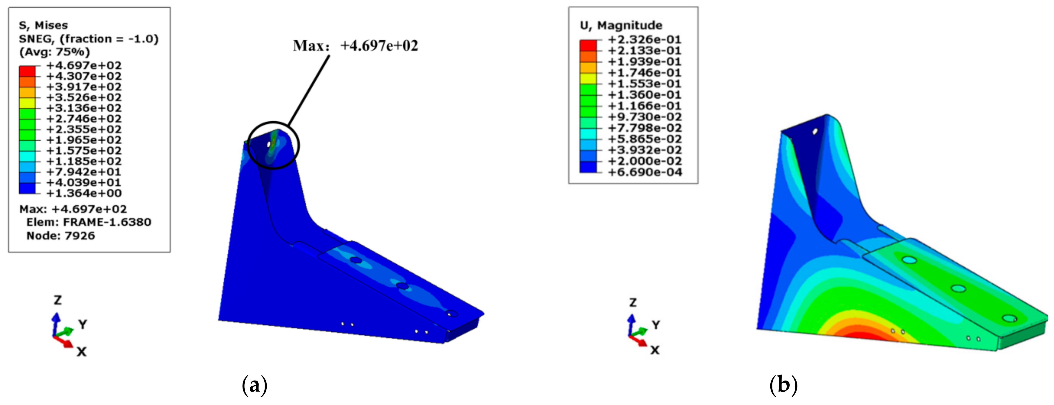
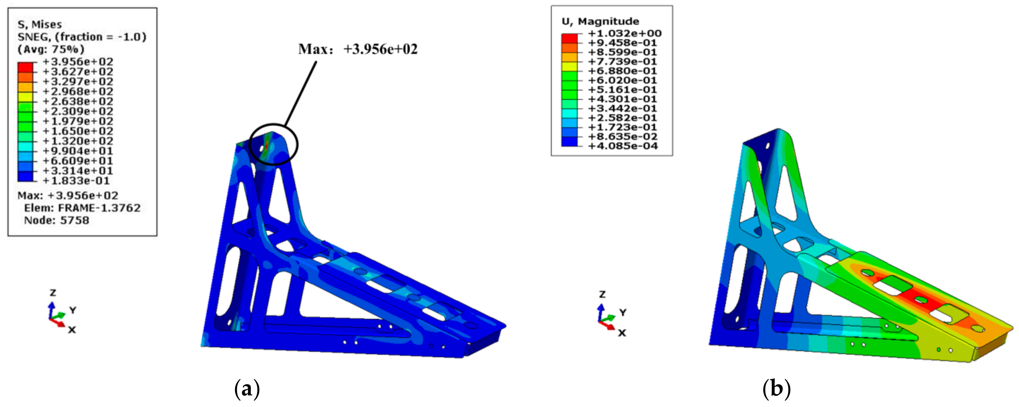
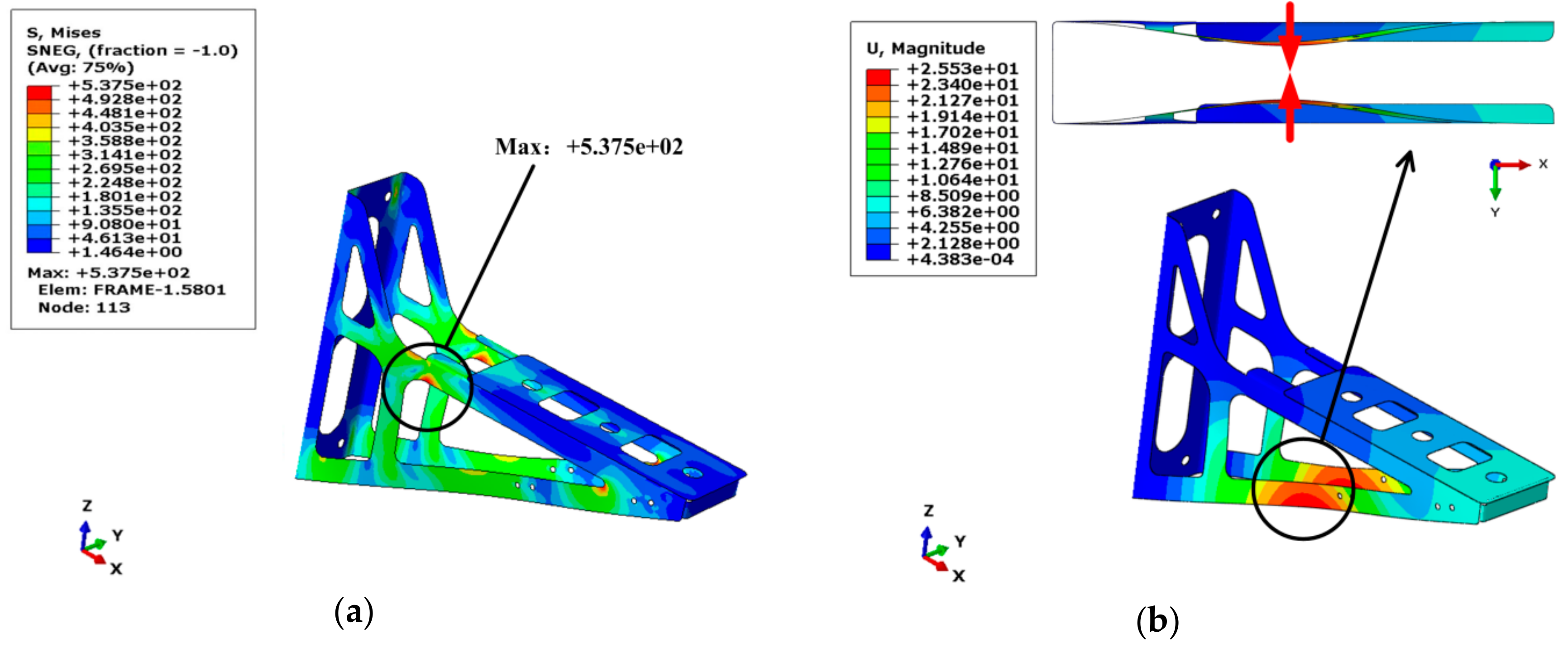
2.2. Finite Element Analysis

The static analysis gives a limit situation which the seat bracket was under the specified load, and can provide an effective reference for the design. According to the structural performance standards established by the user company, when using the calculation to verify the design structure which under a specified load, the structure should have a certain safety margin called the safety factor S calculated by Equation (1).
R L R d S
where, RL represents the yield stress, Rd represents the calculated stress, according to the design requirement the minimum safety factor S is 1.2.
This paper used a static standard method to analyze the initial seat bracket. Figure 2a shows the von-Mises stress nephogram of the initial seat bracket, the stress was evenly distributed on the seat bracket; the maximum stress appeared near the bolts was about 469.7 MPa and the safety factor   S = 2.34 . As shown in Figure 2b, the maximum displacement was 0.2326 mm which appeared on the bottom of the seat bracket side wall. That was because the side wall was lack of effective support in the y-direction, but the deformation was small.

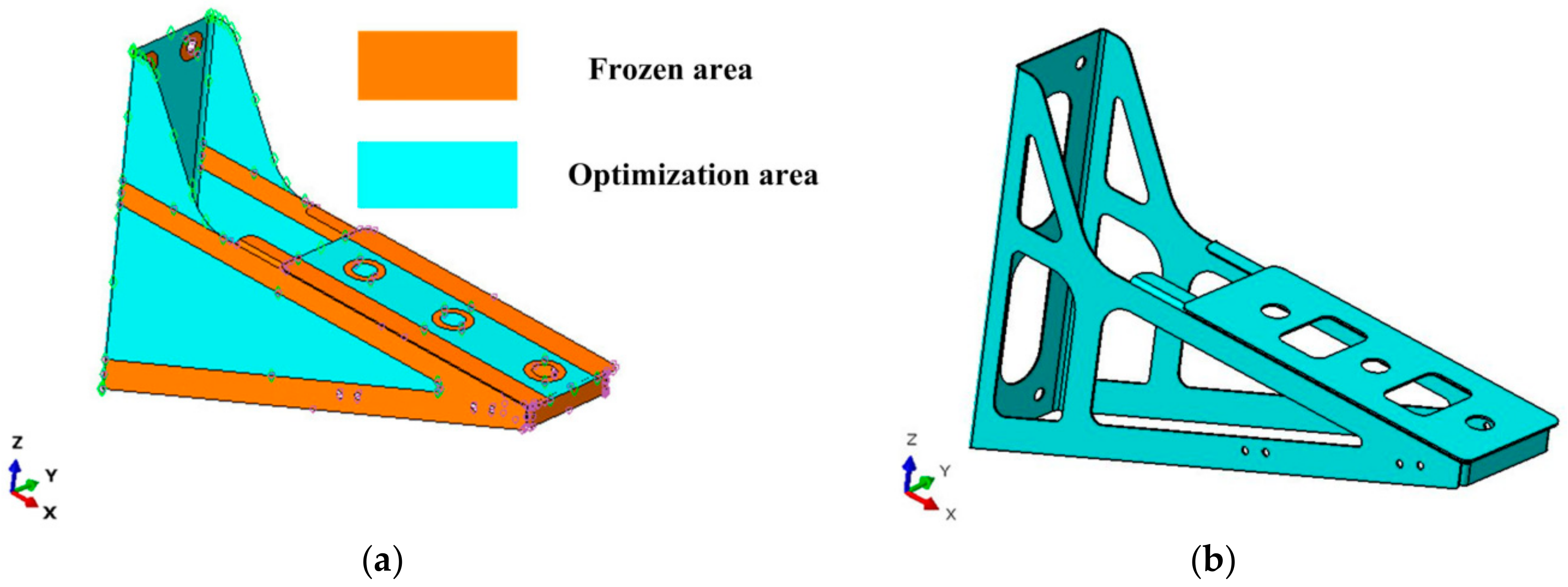
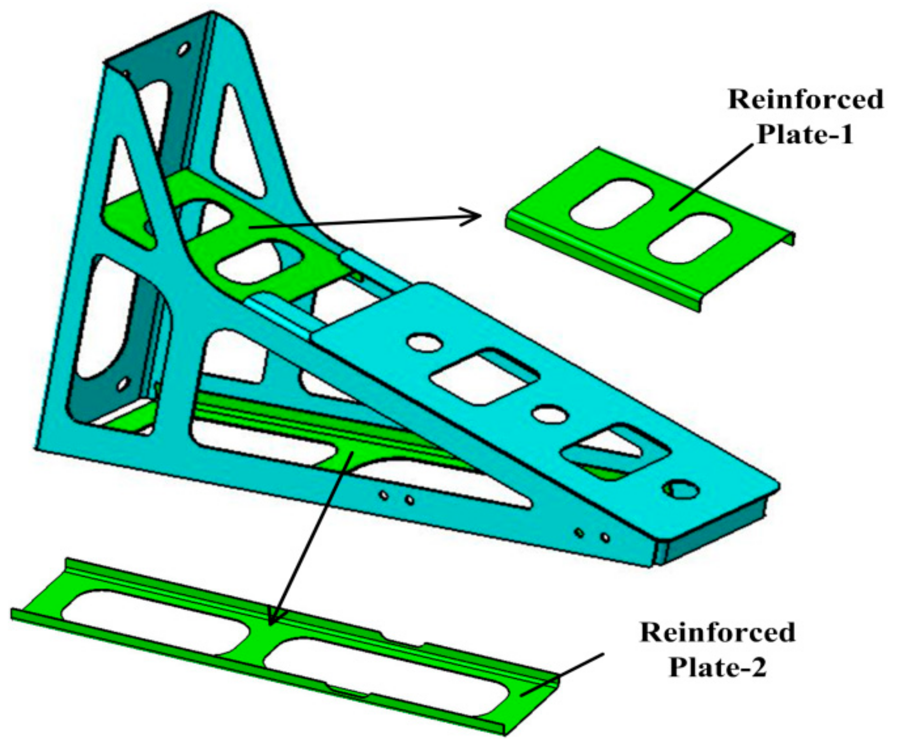
2.3. Topology Optimization Analysis

According to the results, the initial seat bracket has a high safety factor, thus there was a large optimization space to redesign the structure. Structural topology optimization is based on the initial design, the main idea is to convert the optimal topology problem into finding the optimal material distribution for a given design area. The variable density method is a common method for topology optimization, in which a relationship between the elastic modulus of the material and the cell density is established by the SIMP (Solid Isotropic Material with Penalization) interpolation function [18], as shown in Equation (2). In this way, the material distribution problem is transformed into the value of the materials relative density. The relative density is xi, the density of i element is ρ i = χ i ρ i , the penalty factor P is introduced to suppress the intermediate density so that the element density tends to both sides.
E i = E i ρ i = ρ i P E 0 = χ i ρ 0 P E 0 , χ i 0 , 1
where, ρ0 represents the true density of the material, E0 represents the elastic modulus of the material [19,20].
Therefore this paper used the Optimization module to redesign the initial seat bracket; the objective function is to minimize the initial seat bracket strain energy then remove 30% volume of the initial model (V ≤ 0.7 Vinitial) as the optimization constraint. Geometric constraints are additional constraints in topology optimization, which leading us to obtain more realistic optimization results. Thus, the model was divided into optimization area and frozen area, as shown in Figure 3b. The frozen area is used as a geometric constraint to reserve the connection between the components of the seat bracket. Combined with the density distribution after 15 design cycles and considered the possibility to manufacture the seat bracket, the optimized seat bracket model is shown in Figure 3b. After topology optimization, the seat bracket was lighter than the initial seat bracket about 32.15%.
In order to verify the structure, the optimized seat bracket was calculated under the same load. The strength analyzes of the optimized seat bracket are shown in Figure 4. Due to the pressure, the bottom of the seat bracket has a large elastic displacement in the y-direction about 25.53 mm as shown in Figure 4b, and a large stress about 537.5 MPa as shown in Figure 4a, which occurred at the rounded corner of the seat bracket, the safety factor   S = 2.04 .
According to the above analysis, the optimized seat bracket has a large elastic displacement. Therefore, it is necessary to carry out further structural optimization to avoid the bearing capacity due to the excessive displacement. To improve the seat bracket stiffness, this paper welded another two reinforced plates, the final seat bracket is shown in Figure 5.
The strength analyzes are shown in Figure 6, the maximum stress is 395.6 MPa as shown in Figure 6a, the maximum displacement occurred on the top plate about 1.032 mm as shown in Figure 6b, the safety factor   S = 2.84 . The final seat bracket has a high safety factor than the optimized seat bracket, and the displacement in the y direction was greatly suppressed. Although the final seat bracket was increased two reinforced plates, still it was reduced the weight by 17.04% compared with the initial seat bracket.

3. Forming Process and Stiffness Check

3.1. Materials

From the above analyzes, it is known that among the components of the seat bracket the main frame was the most important. Thus, in order to verify the formability of the main frame during the indirect hot stamping process, this paper analyzed the microstructure and mechanical properties of the main frame after quenching. The main frame was using 1.5 mm, non-coated, quenchable 22MnB5 steel sheet provided by Baosteel. The chemical composition of the steel is presented in Table 2.

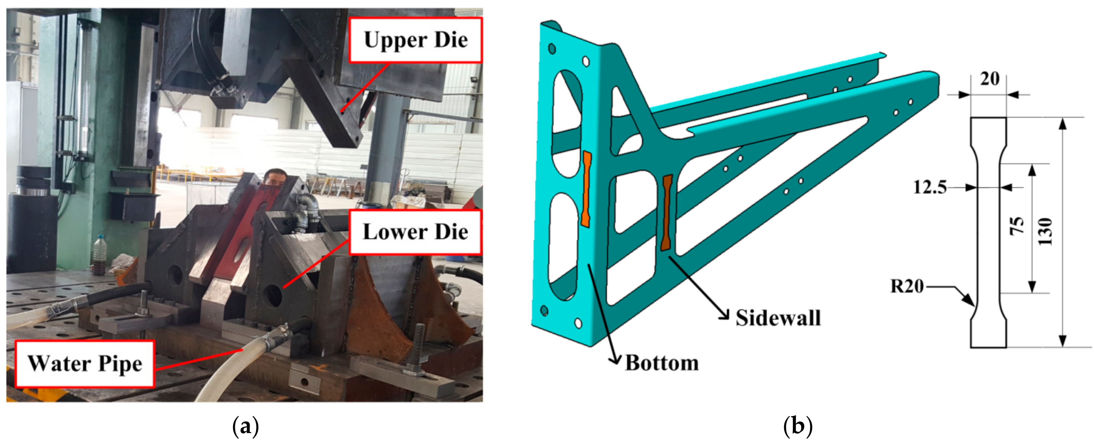
3.2. Indirect Hot Stamping Process

The sheet has been punched and bent as the preformed frame, then the preformed frame was heated to 950 °C in the furnace and held at this temperature for 5 min. After heating, the frame was achieved completely austenitizing. Then the heated frame was transferred to the lower die, the upper die was immediately closed. After the upper and lower dies were completely closed, the contact pressure was applied simultaneously. The contact pressure was 10 MPa and held for 8 s. The objective of the cooling ducts design is to quench the hot sheet effectively and to achieve a cooling rate of at least 27 °C/s, and then the main frame was cooled to room temperature. Figure 7a shows the hot stamping dies, the water and environment temperatures were approximately 20 °C.
After quenching, metallographic observations and mechanical tests were performed to measure the main frame properties. Uniaxial tensile tests were conducted to obtain the material performance parameters. Tensile tests were performed using a Zwick-Z100 materials testing machine (Guangzhou, China). The specimens were cut as per GB/T 228.1-2010, and at least three specimens were tested in each area to ensure repeatability of the test results. Figure 7b shows the geometrical dimension and the place of the specimens, which were tested the bottom (Specimen 1) and the sidewall region (Specimen 2) of the main frame. Then cut at the same place for the microhardness tests and the microstructure observations. The metallographic observations used a TESCAN VEGA3 scanning electron microscope (TESCAN, Brnocity, Czech Republic). Then the microhardness measurements used an HXD-1000 microhardness tester (Shanghai, China) with an experimental force of 2 N and a loading time of 5 s. Then 10 points of each microhardness test samples were measured and the average value was selected for description.
The detail mechanical properties values of the specimens are shown in Table 3. After quenching, the tensile strength of the specimens was greatly improved, and the elongation was reduced. The mechanical properties of the main frame were as good as the expected requirement.

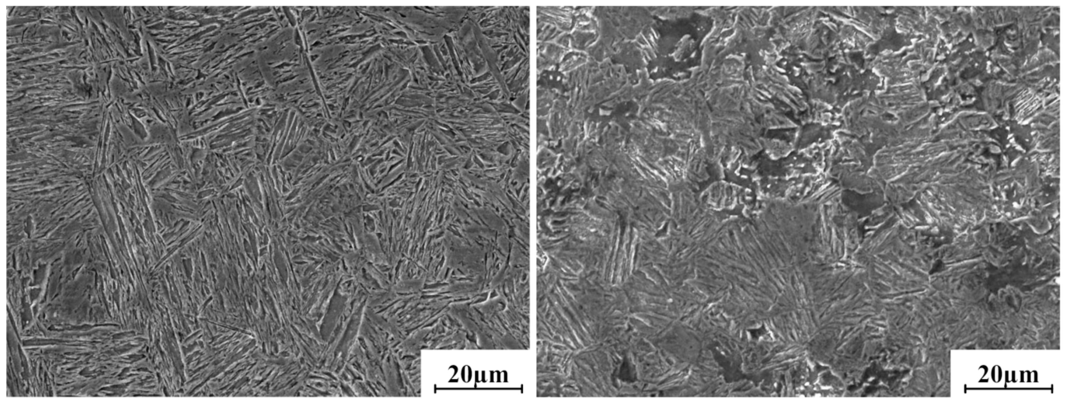
3.3. Microstructures Analysis

After indirect hot stamping, the main frame showed with accurate size and no springback. The specimens were polished, and then etching with 4% nitric acid alcohol solution for 20 s. Figure 8 shows the microstructures of the specimens in different region.
The bottom and sidewall region mostly showed with lath martensite, whereas the sidewall region has less bainite and ferrite. As evident in Figure 8, the martensite in the bottom region was more slender than in the sidewall region. The distribution of the microhardness values were consistent with the results of the microstructure results, in which the sidewall region has lower microhardness values than the bottom region. The reason is that the bottom region was quenched under higher contact pressures than the sidewall region. During the quenching process, the cooling rate of the bottom region was reached 27 °C/s, thus the austenite was completely transformed into martensite. However, the cooling rate of the sidewall region was less than 27 °C/s, then before the martensite transformation, some austenite transformed into ferrite and bainite. The sidewall region was under no pressure and the cooling effect was insufficient. Therefore, the sidewall region has different phase microstructures. In conclusion, the main frame was satisfied with the production expectation.

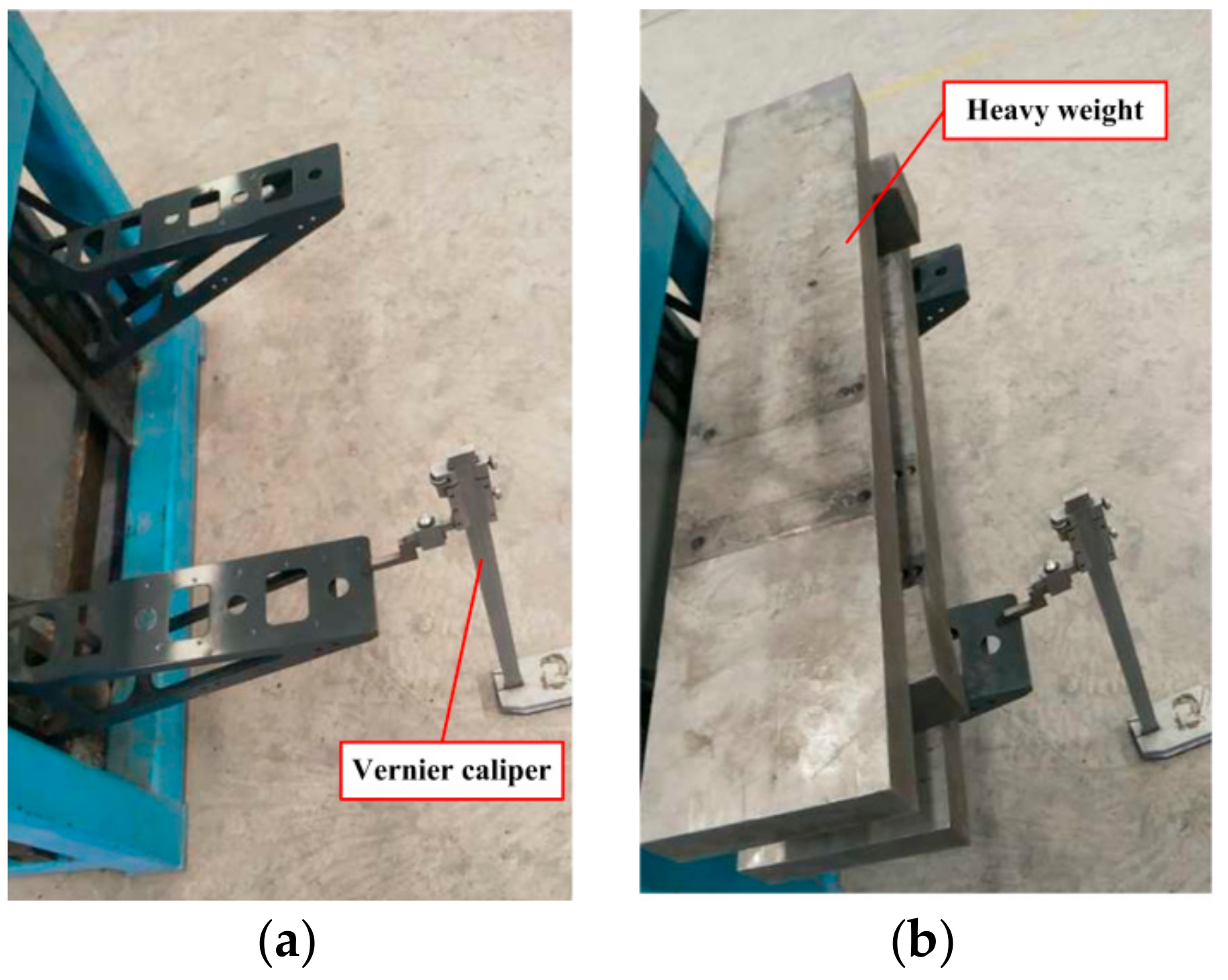
3.4. Stiffness Check Test

After quenching, in order to reduce the internal stress and prevent the brittle failure of the main frame, the main frame was tempered at 150 °C for 40 min to improve the overall performance of the structure, and then cooled to room temperature. Then the main frame was welded with two reinforced plates to get the final seat bracket. The stiffness of the seat bracket was inspected and compared with the finite analyzes results. During the test, two-seat brackets were loaded with a heavy weight about 300 kg as shown in Figure 9. Subsequently, the vertical displacement of the seat bracket can be obtained by measuring the distance between the seat bracket subplate and the ground before and after loading. The vertical displacement was used to evaluate the stiffness of the seat bracket.
According to the measurement results, before loading the distance between the sub-plate and the ground was 499 mm, after loading the distance was 498.6 mm. The seat bracket displacement was about 0.4 mm, which means the seat bracket has small deformation under the specified load. From the above finite element results, the displacement in the y direction is about 0.681 mm. Eventually, the measurement results were basically in agreement with the finite element results.

4. Conclusions

(1)
A new seat bracket was designed according to finite element analysis and topology optimization results; the results showed that the new seat bracket can reduce the weight by 17.04% after topology optimization.
(2)
The reasonable parameters during the indirect hot stamping process were that the main frame was heated to 950 °C and held at this temperature for 5 min. During quenching, the contact pressure was 10 MPa and held at this pressure for 8 s, and then the main frame was transformed to martensite. After indirect hot stamping, the seat bracket was showed with accurate size and no springback.
(3)
During the quenching stage of the indirect hot stamping, the bottom region is fully quenchable compared to the sidewall region. The cooling rate of the bottom region reached 27 °C/s, thus the austenite was completely transformed into martensite. However, the cooling rate of the sidewall region was less than 27 °C/s, then before the martensite transformation, some austenite transformed into ferrite and bainite.
(4)
According to the stiffness check test, the seat bracket has tiny deformation under the specified load, and the inspect results were basically consented to the finite element results, which verified the rationality of the seat bracket design.

Author Contributions

Software, L.J.; formal analysis, H.X.; investigation, X.L.; writing—original draft, Z.T.; writing—review and editing, G.Y.; visualization, L.Z.; supervision, Z.G.

Acknowledgments

This work was financially supported by the National Natural Science Foundation of China (No.51101072) and Technology Development Program of Jilin Province (No.20160204058GX and No.3R2197212416).

Conflicts of Interest

The authors declare no conflict of interest.

References

  1. Adheesh, S.R.; Vasisht, S.M.; Ramasesha, S.K. Air-pollution and economics: diesel bus versus electric bus. Curr. Sci. 2016, 110, 858–862. [Google Scholar]
  2. Li, J.Q. Battery-electric transit bus developments and operations: A review. Int. J. Sustainable Transp. 2016, 10, 157–169. [Google Scholar] [CrossRef]
  3. Dvorak, P. Fea and Optimization Leads to a More-Efficient Design Process. Mach. Des. 2001, 73, 54. [Google Scholar]
  4. Li, C.; Kim, I.Y.; Jeswiet, J. Conceptual and detailed design of an automotive engine cradle by using topology, shape, and size optimization. Struct. Multi. Optim. 2014, 51, 547–564. [Google Scholar] [CrossRef]
  5. Li, C.; Kim, I.Y. Topology, size and shape optimization of an automotive cross car beam. Proc. Inst. Mech. Eng. D 2014, 229, 1361–1378. [Google Scholar] [CrossRef]
  6. Yildiz, A.R. Optimal structural design of vehicle components using topology design and optimization. Mater. Test. 2008, 50, 224–228. [Google Scholar] [CrossRef]
  7. Yildiz, A.R. A new hybrid particle swarm optimization approach for structural design optimization in the automotive industry. Proc. Inst. Mech. Eng. D 2012, 226, 1340–1351. [Google Scholar] [CrossRef]
  8. Choi, H.S.; Kim, B.M.; Nam, K.J.; Ha, S.Y.; Cha, S.H.; Kang, C.G. Development of hot stamped center pillar using form die with channel type indirect blank holder. Int. J. Automot. Technol. 2011, 12, 887–894. [Google Scholar] [CrossRef]
  9. Hafenstein, S.; Werner, E.; Wilzer, J.; Theisen, W.; Weber, S.; Sunderkötter, C.; Bachmann, M. Influence of temperature and tempering conditions on thermal conductivity of hot work tool steels for hot stamping applications. Steel Res. Int. 2015, 86, 1628–1635. [Google Scholar] [CrossRef]
  10. Pedraza, J.P.; Landa-Mejia, R.; García-Rincon, O.; Isaac Garcia, C. The effect of rapid heating and fast cooling on the transformation behavior and mechanical properties of an advanced high strength steel (AHSS). Metals 2019, 9, 545. [Google Scholar] [CrossRef]
  11. Mori, K.; Bariani, P.F.; Behrens, B.A.; Brosius, A.; Bruschi, S.; Maeno, T.; Merklein, M.; Yanagimoto, J. Hot stamping of ultra-high strength steel parts. CIRP Ann. 2017, 66, 755–777. [Google Scholar] [CrossRef]
  12. Naderi, M.; Ketabchi, M.; Abbasi, M.; Bleck, W. Analysis of microstructure and mechanical properties of different high strength carbon steels after hot stamping. J. Mater. Process. Technol. 2011, 211, 1117–1125. [Google Scholar] [CrossRef]
  13. Karbasian, H.; Tekkaya, A.E. A review on hot stamping. J. Mater. Process. Technol. 2010, 210, 2103–2118. [Google Scholar] [CrossRef]
  14. Chowdhury, M.N.; Kim, J.-R.; Hong, S.-T.; Jung, J.-W.; Han, H.-N.; So, S.-W. Tailoring of mechanical properties of indirect hot stamping steel tubes by laser assisted local rapid heating. J. Iron. Steel Res. Int. 2016, 23, 949–954. [Google Scholar] [CrossRef]
  15. Hippchen, P.; Lipp, A.; Grass, H.; Craighero, P.; Fleischer, M.; Merklein, M. Modelling kinetics of phase transformation for the indirect hot stamping process to focus on car body parts with tailored properties. J. Mater. Process. Technol. 2016, 228, 59–67. [Google Scholar] [CrossRef] [Green Version]
  16. Hwang, J.S.; Moon, J.H.; Kang, C.-G. Prediction of springback during indirect hot press forming through tensile test with simultaneous cooling. Proc. Inst. Mech. Eng. B 2013, 227, 1013–1022. [Google Scholar] [CrossRef]
  17. Seo, H.Y.; Jin, C.K.; Kang, C.G. Effect on blank holding force on blank deformation at direct and indirect hot deep drawings of boron steel sheets. Metals 2018, 8, 574. [Google Scholar] [CrossRef]
  18. Rietz, A. Sufficiency of a finite exponent in simp (power law) methods. Struct. Multi. Optim. 2001, 21, 159–163. [Google Scholar] [CrossRef]
  19. Belblidia, F.; Lee, J.E.B.; Rechak, S.; Hinton, E. Topology optimization of plate structures using a single- or three-layered artificial material model. Adv. Eng. Software 2001, 32, 159–168. [Google Scholar] [CrossRef] [Green Version]
  20. Sigmund, O. Materials with prescribed constitutive parameters: An inverse homogenization problem. Int. J. Solids Struct. 1994, 31, 2313–2329. [Google Scholar] [CrossRef]
Figure 1. Structural schematic diagram of one seat (a) and (b) initial seat bracket.
Metals 09 00833 g001
Figure 2. Von Mises stress nephogram (a) and (b) displacement nephogram of the initial designed seat bracket.
Metals 09 00833 g002
Figure 3. Seat bracket before optimization (a) and (b) after optimization.
Metals 09 00833 g003
Figure 4. Von Mises stress nephogram (a) and (b) displacement nephogram of the optimized seat bracket.
Metals 09 00833 g004
Figure 5. Structural schematic diagram of the final seat bracket.
Metals 09 00833 g005
Figure 6. Von Mises stress nephogram (a) and (b) displacement nephogram of the final seat bracket.
Metals 09 00833 g006
Figure 7. Hot stamping dies (a) the positions and the geometrical dimension of the specimens (mm) (b).
Metals 09 00833 g007
Figure 8. (a) Microstructures of the bottom and (b) sidewall region after quenching.
Metals 09 00833 g008
Figure 9. Stiffness check test. Seat bracket before (a) and after loading (b).
Metals 09 00833 g009
Table 1. Material parameters of the initial seat bracket.
MaterialsDensity (g/cm3)Elasticity Modulus (GPa)Poisson’s RatioU.T.S (MPa)
SUS3047.941940.3264
Q3457.852100.3345
22MnB57.892120.31152
Table 2. Chemical composition of the 22MnB5 steel (wt%).
CMnSiCrBP
0.22–0.251.2–1.40.2–0.30.11–0.20.002–0.004≤0.02
Table 3. The mechanical properties of the specimens.
Mechanical Properties Specimen 1Standard DeviationSpecimen 2Standard Deviation
Tensile strength (MPa)15603.3214225.54
Microhardness (HV)513.50.46489.51.05
Elongation (%)4.80.026.90.04
Elasticity modulus (GPa)211.069.8190.6610.2

