Article

Formability Analysis and Oxidation Layer Effects in Dieless Drawing of Stainless Steel Wires

Department of Mechanical and Electro-Mechanical Engineering, National Sun Yat-sen University, No.70 Lianhai Rd., Gushan Dist., Kaohsiung City 804, Taiwan
*
Author to whom correspondence should be addressed.
Metals 2019, 9(8), 828; https://doi.org/10.3390/met9080828
Submission received: 14 June 2019 / Revised: 16 July 2019 / Accepted: 22 July 2019 / Published: 25 July 2019
(This article belongs to the Special Issue Metal Micro-forming)

Abstract

:
In this study, dieless drawing experiments of stainless steel SUS304 wires of 1 mm in diameter were carried out using a self-developed dieless drawing machine. In order to prevent oxidation, argon gas was applied to a self-designed chamber during dieless drawing processes. The effects of the forming temperature and the oxide layer on the mechanical properties of the drawn SUS304 stainless wires obtained by tensile tests are discussed in this paper. A finite element model considering the high frequency induction heating mode in the finite element software DEFORM2D was developed to conduct the heat transfer analysis and the formability analysis of the drawn products in dieless drawing of stainless steel wires. The effects of the drawing speed and forming temperature on the maximal reachable area reductions are discussed. Through the comparisons of the maximal reachable area reduction between the finite element simulations and experiments, the finite element modelling for dieless drawing processes was validated.

1. Introduction

Weiss and Kot first proposed the idea of a dieless drawing process, which can reduce the cross-section of a wire without using a die, in 1969 [1]. There are no friction or lubrication problems between the workpiece and the die during the process. Compared with the traditional die drawing processes, dieless drawing has some advantages, such as no dies in the process, a larger area reduction at a single pass, no need for special surface treatment of the workpieces, a more flexible process, and so on. Recently, due to prominent development of micro-electro-mechanical-systems (MEMS) and biomedical technology, micro-metal forming has drawn more attention and demand for microtubes and microwires has increased dramatically [2]. Furushima and Manabe [3] have successfully manufactured micron-sized tubes of a diameter of 190 μm using dieless drawing processes.
Some research on analytical and experimental modelling in a dieless drawing process has been published. For example, Fortunier et al. [4] used a simple slice method and divided the wire into three zones to analyze the stability problems during dieless wire drawing processes. Wang et al. [5] investigated experimentally the wall thickness variation during drawing of stainless steel tube. Tubes with various inner and outer diameters were used and the effects of the area reduction were discussed. Wang et al. [6] also derived a velocity field and determined the drawing force using a power equivalent method during dieless tube drawing. The drawing force is affected by the width of deformation fields, sectional reduction ratios, deformation temperatures, and the drawing speed. Furushima et al. [7] proposed a drawing path control method during the drawing process to restrain the unstable deformation. The real deformation limit of the material was investigated by coupling the thermos-mechanical finite element analyses and experiments of the dieless drawing process. Furushima and Manabe [8] proposed an approach for fabrication of superplastic microtubes using a high-frequency induction heating apparatus and an air-cooling nozzle in a multi-pass dieless drawing process. After four-pass dieless drawing, a microtube with outer and inner diameters of 190 and 91 μm, respectively, was achieved successfully.
Furushima and Manabe [9] investigated the size effect on the deformation and heat transfer behavior of microtubes during a dieless drawing process using finite element analysis. They found that heat is not conducted from the outside surface to the inside of a macroscale tube in the case of very high-speed drawing. In contrast, due to the size effect at the microscale, the temperature of the outside surface and the inside of microtubes can be increased rapidly. Therefore, high-speed drawing can be realized for microtube dieless drawing. Furushima et al. [10] investigated the effects of surface roughening and oxidation on the drawing limit in dieless drawing of SUS304 stainless steel microtubes. They found that the limiting area reduction increases to a maximal value and then decreases with heating temperatures in both air and argon gas. The appropriate heating temperatures ranged from 950 to 1100 °C for the maximal drawing limit. Furushima et al. [11] used a laser irradiated from one direction of a metal microtube to propose a novel rotary laser dieless drawing process. They evaluated the rotating effects on outer diameter variations and outer radius errors in laser dieless drawing of stainless steel SUS304 microtubes. Milenin [12] used the special features of rheology to propose an approach to reduce the unevenness of the drawn product profile by dividing the drawing process into a few stages. The values of the strains in each stage correspond to the area of intensive hardening on the stress–strain curves of the processed material.
Some research about dieless drawing machines has been reported. For example, Twohig et al. [13] used a forward non-continuous dieless drawing machine to investigate dieless drawing of a 5 mm-diameter nickel-titanium rod. The effects of different forming parameters on the changes in microstructure were understood through hardness testing and microstructure observation. Naughton and Tiernan [14] pointed out that the reason that the dieless drawing method has not been fully accepted by the industry is that the forming system is unstable. Data collection and actuation control in the experimental process are the key components when designing and manufacturing the dieless drawing machine. A stability design for a continuous dieless drawing system has been proposed. Tiernan et al. [15] carried out dieless drawing experiments on AISI O1 steel wires. The experimental results showed that when the speed ratio is greater than 0.5, a large reduction and uniform diameter could be obtained. A load control system was developed to increase the formability of the product and reduce the product diameter tolerance to 0.01–0.05 mm. Supriadi and Manabe [16] used a visual sensor to monitor the minimum diameter of the deformation zone during dieless drawing to improve the diameter uniformity of the drawn product. The combination of the dieless pumping method and image recognition technology was first presented in their paper.
When the drawn metal is exposed to the atmosphere at a higher temperature, oxidation occurs and an oxide layer is generated on the product surfaces. The oxide layer protecting the inside material may break or crack due to uneven thermal or tensile stresses and lose its protective function. Eventually, the inside material will be oxidized more, which may result in poor surface quality. So far, few works discussed the formation of oxide layers and the effects of the oxide layers on the mechanical properties in dieless drawing of stainless steels. In this study, the formation of oxide layers and their effects on the mechanical properties of the dieless drawn SUS304 wires were investigated. Argon gas was used to surround the drawn wire to prevent the oxidation of the stainless steel during the dieless drawing processes. Tensile tests of stainless steel wires were conducted and the effects of the oxide layer on the mechanical properties are discussed in this paper. Also presented is a series of formability analyses of a wire dieless drawing process using DEFORM software coupled with a high frequency induction mode, which is different to the traditional approach of using a constant temperature zone moving with heating coil position during the drawing process.

2. Dieless Drawing Experiments

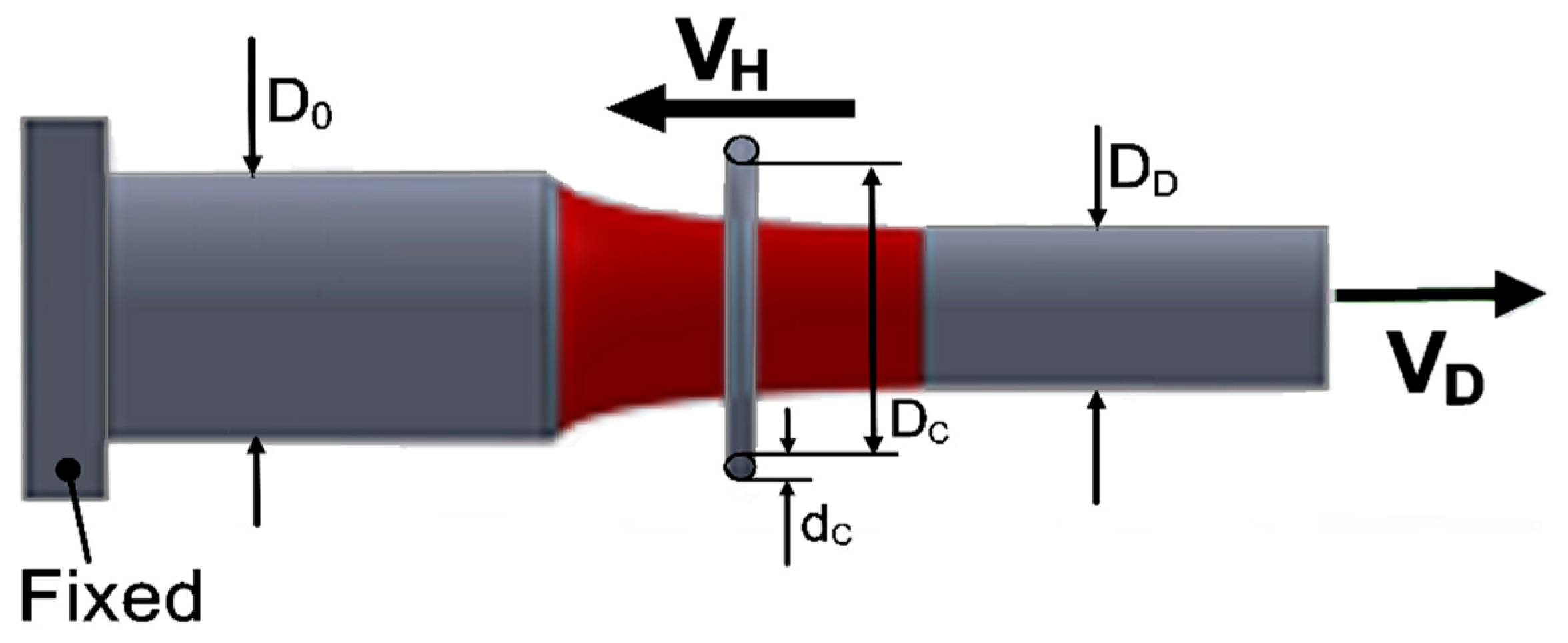
According to the movement direction of the heating coils, dieless drawing can be operated in three types of set-ups [17]: (a) continuous drawing type; (b) backward non-continuous drawing type; and (c) forward non-continuous drawing type, in which the heating coil is fixed, moves backward, and moves forward, respectively. A dieless drawing machine was developed by the present authors. The self-developed dieless drawing machine type is the same as that used by Weiss and Kot [1], a backward non-continuous drawing type, as shown in Figure 1.
The area reduction in the dieless drawing process was determined according to the relationship between the drawing and heating coil speeds. From volume constancy, we get:
AO VH = AD (VD + VH)
where VD and VH are the drawing and heating coil speeds, respectively. AO and AD are the cross-sectional areas of the wire before and after drawing, respectively. The area reduction R can be expressed as the function of VH and VD as given below [18].
R = 1   A D A 0 =   1   V H V D + V H
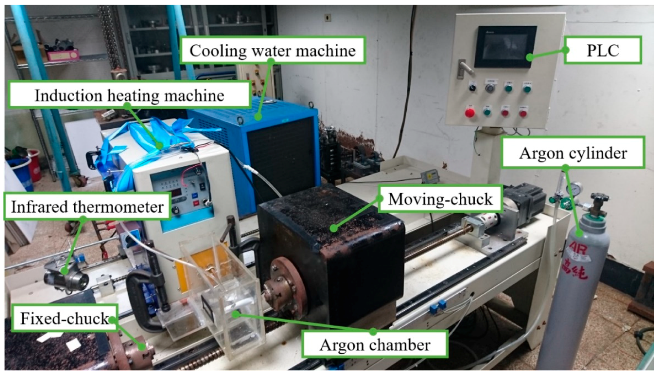
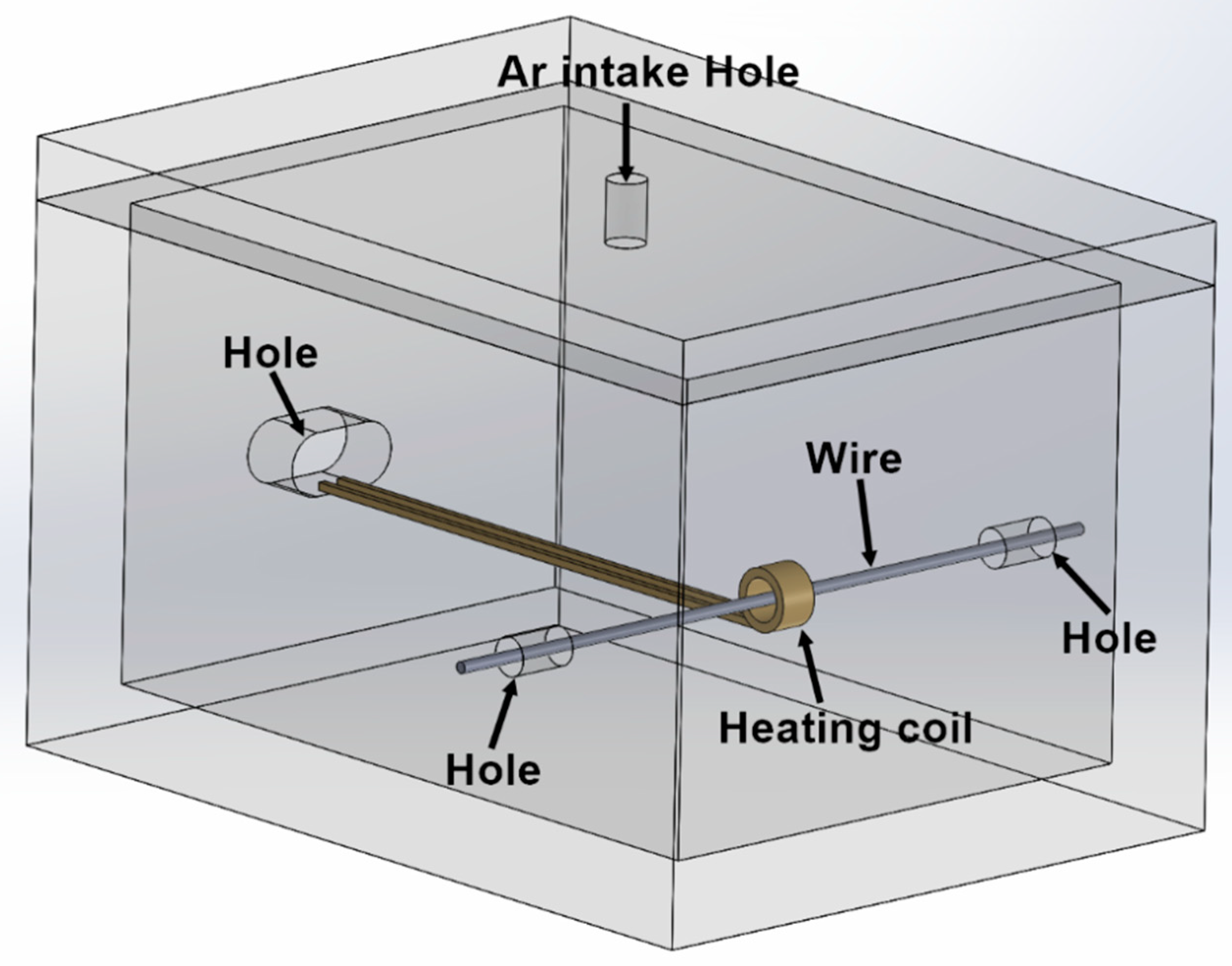
A dieless drawing prototype machine was developed for tube or wire drawing processes. This self-developed dieless drawing machine was composed of three main parts: a supporting frame, a heating apparatus, two transmission systems and a control system [19]. The appearance of the completed prototype machine is shown in Figure 2. The heating apparatus, composed of a high frequency heater device and a heating coil, was designed to heat up the workpiece at a narrow heating zone. A cooling system was designed to cool down the workpiece at a cooling zone next to the heating zone. The temperature and drawing speed variations were recorded during the dieless drawing process. During the drawing process, one end of the wire workpiece was clamped at the fixing table, and the other end was clamped at the drawing table, which speed was controlled by a servomotor through a lead screw. The heating table and heating coils were moved by another servomotor in the opposite direction to that of the drawing table. The relative speed ratio of the heating coils to the drawing table was used to control the area reduction of the wire workpiece. The high-frequency induction heating apparatus was used to heat locally the wire and the infrared thermometer was used to measure the heating temperature. In order to avoid oxidation on the surface at the wire heating zone, argon gas was input into an argon gas chamber to enclose the whole wire surface at the heating zone. The argon gas chamber shown in Figure 3 was assembled by six acrylic plates and four small holes drilled on the plates were used for letting the wire, heating coil, and argon gas pass into the chamber.
Before the dieless drawing experiments, the moving chuck and induction heating apparatus were calibrated to the set positions. Then, a stainless steel wire was moved to pass through the argon gas chamber and the center of the heating coil. The two ends of the wire were fixed at the fixed chuck and the moving drawing chuck. The measuring point of the infrared thermometer was adjusted to locate at the center of the wire and at the center of the heating coil to measure accurately the wire temperature during drawing. After that, an argon valve was opened to let the argon gas flow into the chamber continuously at a flow rate of 10 L/min for about 60 s to ensure no air existing inside the chamber. Finally, the drawing parameters of drawing speed, heating coil speed and heating temperature were input into the control panel, and then the dieless drawing experiment was started.
Stainless steel SUS304 wires with a diameter of 1 mm were used in the experiments. A series of experiments of dieless drawing processes were conducted under an atmosphere in air and argon gas. As the other parameters have relatively small effects on the oxide layers, only the forming temperature and the atmosphere were considered at several levels and the other parameters were fixed. The forming conditions for the experiments are shown in Table 1.

3. Experimental Results and Discussion

3.1. Product Surface Observation

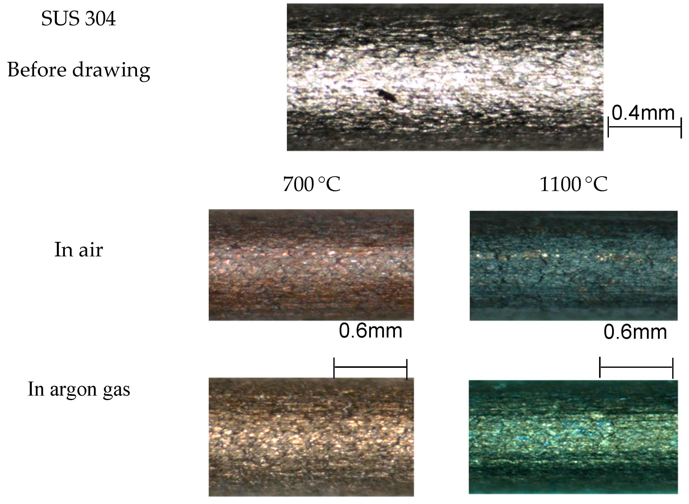
The surface appearance of the stainless steel wires before and after drawing at different drawing temperatures and in different atmospheres is shown in Figure 4. It can be found that the surfaces of drawn wires exhibit different colors at different temperatures. As the forming temperature increases from 700 to 1100 °C, the wire surface becomes darker and the oxidation layer becomes thicker. The results indicate that even though the wire was drawn in argon gas, slight oxidation still occurred.
The oxides were very brittle and undergo fracture easily at the early stage of deformation, which usually resulted in the thickness variation of the oxide layer. According to Qin et al. [20], the structures of the oxide layer are mainly Fe3O4 and FeCr2O4. The diameter of the wire was so small that it is difficult to measure the surface roughness of the oxide layer. The thickness of the oxide layer exhibited some variation of about 1–7 µm, which is quite close to the results in Qin et al. [20]. Generally the thickness of the oxide layer increased with the forming temperature and the surface color of the product became slightly darker as the forming temperature increased. The surface colors of the products at 700 °C and 1100 °C exhibited more vivid contrast. Thus, only the appearance of the products at temperatures of 700 °C and 1100 °C is shown in Figure 4.

3.2. Mechanical Properties of Drawn Wires

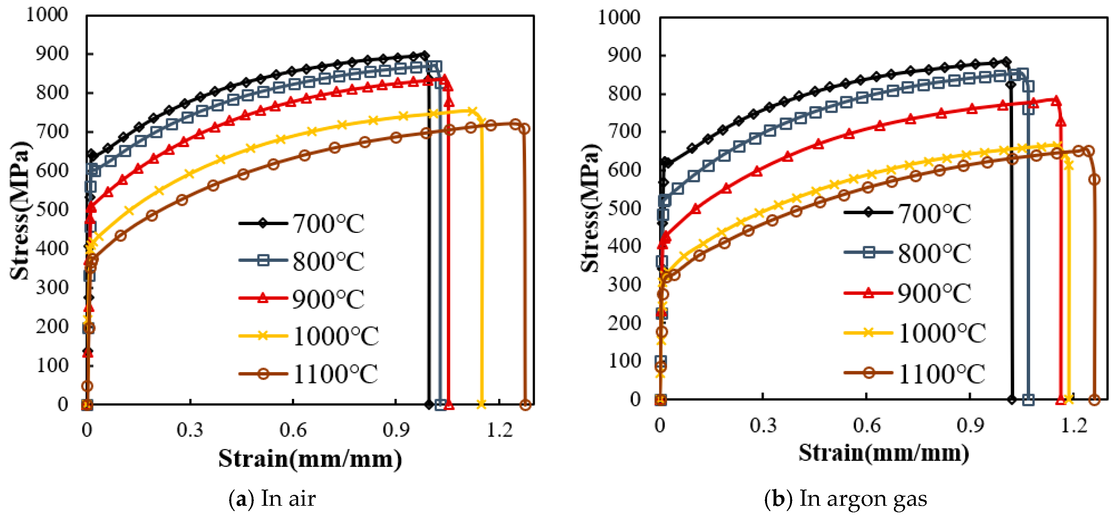
To investigate the effects of the oxide layer and forming temperature on the mechanical properties of the drawn wires, tensile tests were conducted at room temperature. The specimen gauge length was 30 mm and the tensile test speed was set as 10 mm/min. The engineering stress-strain curves of the drawn wires at different forming temperatures and in different atmospheres are shown in Figure 5. The yield stress, ultimate tensile strength (UTS) and elongation of the drawn products could be obtained from the stress-strain curves. Generally, the yield stress and ultimate tensile strength decreased with increases in the forming temperature in both air and argon gas.
The yield stresses of the drawn wires were obtained from the engineering stress-strain curves using the 0.2% offset method. The yield stresses at different forming temperatures in air and argon gas are shown in Figure 6. From the figure it is knows that as the forming temperature increased, the yield stresses of the drawn wires decreased. The yield stresses in air were higher than those in argon gas.
The ultimate tensile strengths (UTSs) at different forming temperatures in different atmospheres are shown in Figure 7. It is clear that the UTS decreased as the forming temperature increased, just as the case of yield stress. The UTSs of the drawn wires in air were slightly higher than those in argon gas. Because the strength of the oxide layer was generally larger than that of stainless steel SUS304.
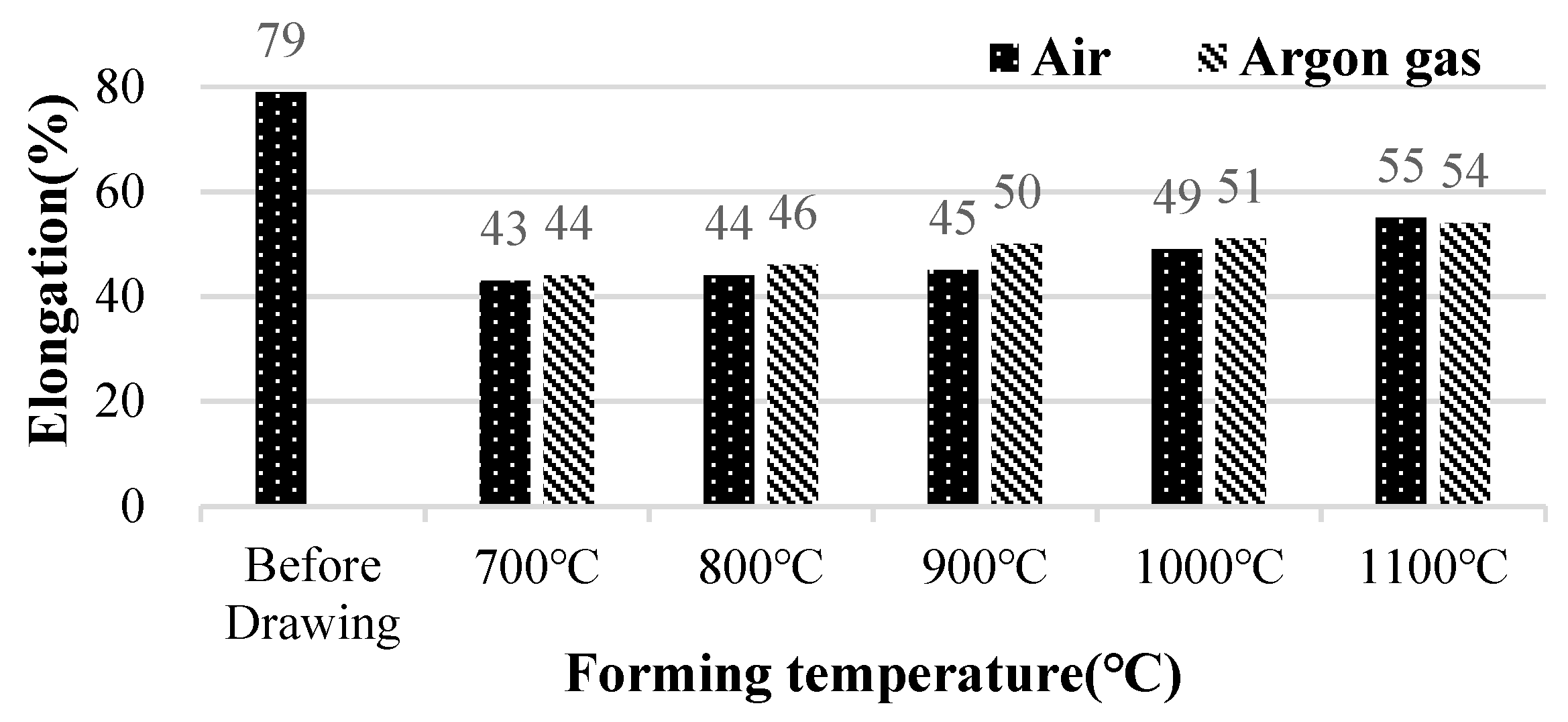
The elongations at different forming temperatures in different atmospheres are shown in Figure 8. We can find that the elongation increased as the forming temperature increased. The elongations of the drawn wires in argon gas were slightly higher than those in air. The elongations of the drawn products were all smaller than the initial wire elongation.

4. Finite Element Simulations

4.1. Finite Element Modelling with Induction Heating Mode

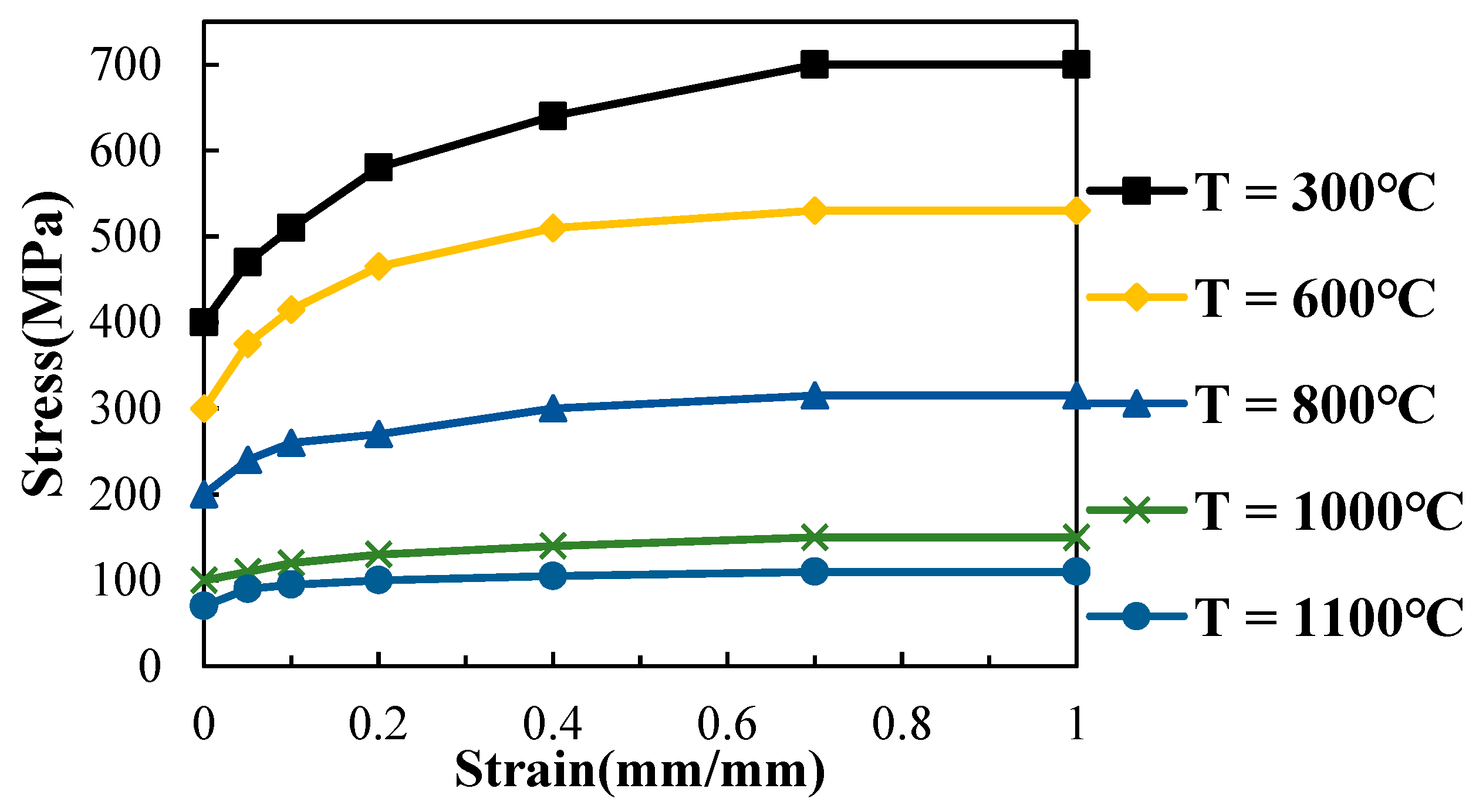
In this study, a high-frequency induction heating apparatus was used to heat the wire during dieless drawing. Therefore, a software DEFORM coupled with the induction heating mode was used, in which a boundary element method is used to analyze the heat transfer during the dieless drawing process. The flow stress curves of stainless steel SUS304 wires at different temperatures from the DEFORM database shown in Figure 9 were used. The strain rate variation in the dieless drawing process was not so big. The average strain rate was about 0.25. Therefore the strain rate effect was not taken into account. The electrical resistivity of the wire at 20 °C and 650 °C were set as 0.00072 and 0.00116 Ω·mm, respectively. The relative magnetic permeability was set as 1.02. After that, the current frequency and input power inside the induction coil were set. After element meshing in the wire was completed, the thermal conductivity of the wire at 100 °C and 500 °C were set as 17 and 22 W·m−1·K−1, respectively. The convection coefficient of the atmosphere was set as 70 W·m−2·K−1.
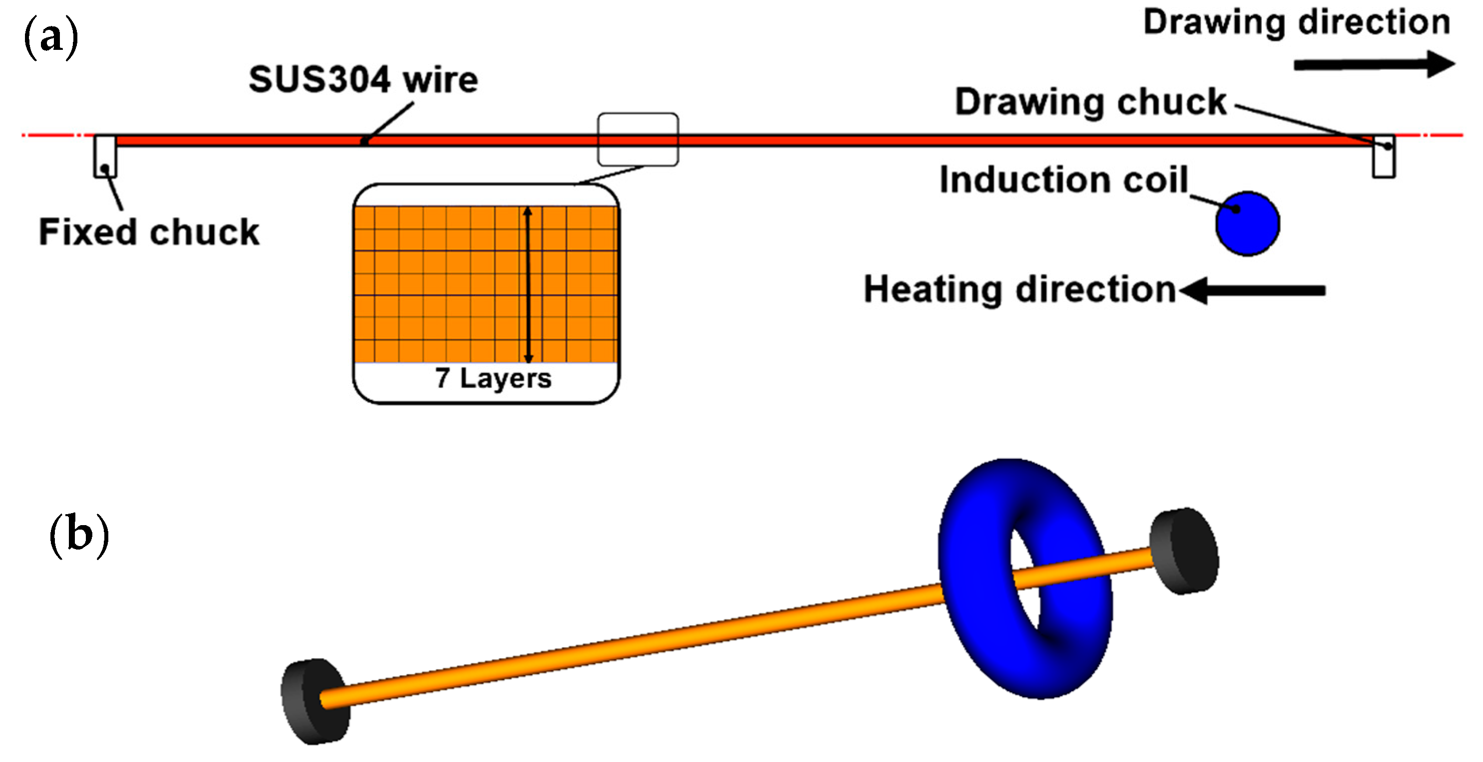
The configuration of the meshed wire and heating coil is shown in Figure 10a. The wire and the circular heating coil were axisymmetric, thus, DEFORM 2D was used to reduce the simulation time. The corresponding three dimensional perspective view of the wire and heating coil is shown in Figure 10b. Convergence analysis with different mesh numbers and different layers inside the wire were conducted. With 7 mesh layers in the radial direction and about 5500 mesh numbers, reasonably accurate simulation results within an error of 0.7% could be obtained. The accuracy of 0.7% in the simulation results of wire diameters is convergence accuracy with different element numbers inside the wire, which means even though many more element numbers were set, the variations of the simulation results were within 1%.

4.2. Formability Analysis

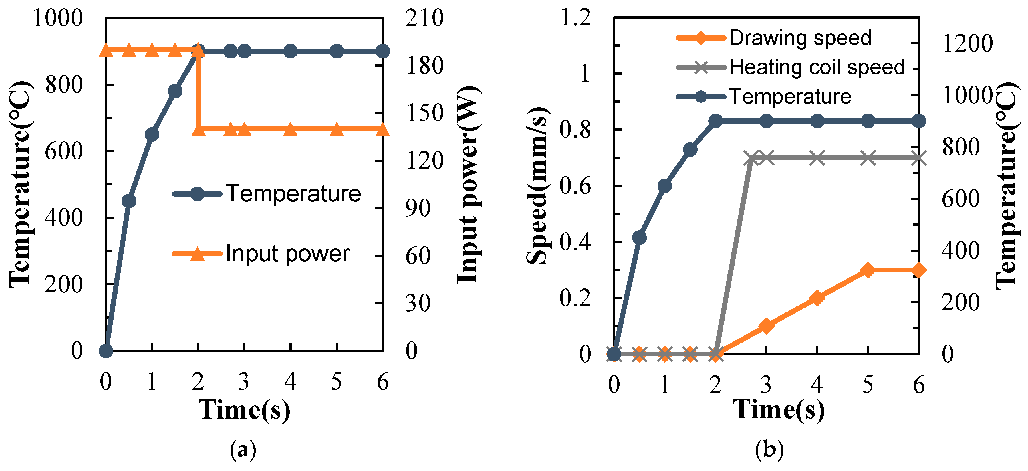
The drawing speed and the forming temperature are the key parameters that determine if a successful wireless drawing process can be achieved or not. Formability analysis with different drawing speeds on the maximal reachable area reductions was conducted. The parameters used in the formability analysis are shown in Table 2. The relationships between the forming temperature variation and the input power of 180 W are shown in Figure 11a. The relationships between the heating coil speed, drawing speed and forming temperature variation are shown in Figure 11b. The profiles of the heating coil speed and drawing speed are that same as those used in the self-developed dieless drawing machine. The values of input power, heating coil speed, drawing speed are input in the finite element (FE) simulations for formability analysis. After a series of formability analysis, formability experiments for the maximal reachable area reduction using the self-developed dieless drawing machine are also conducted.

5. Formability Simulation Results

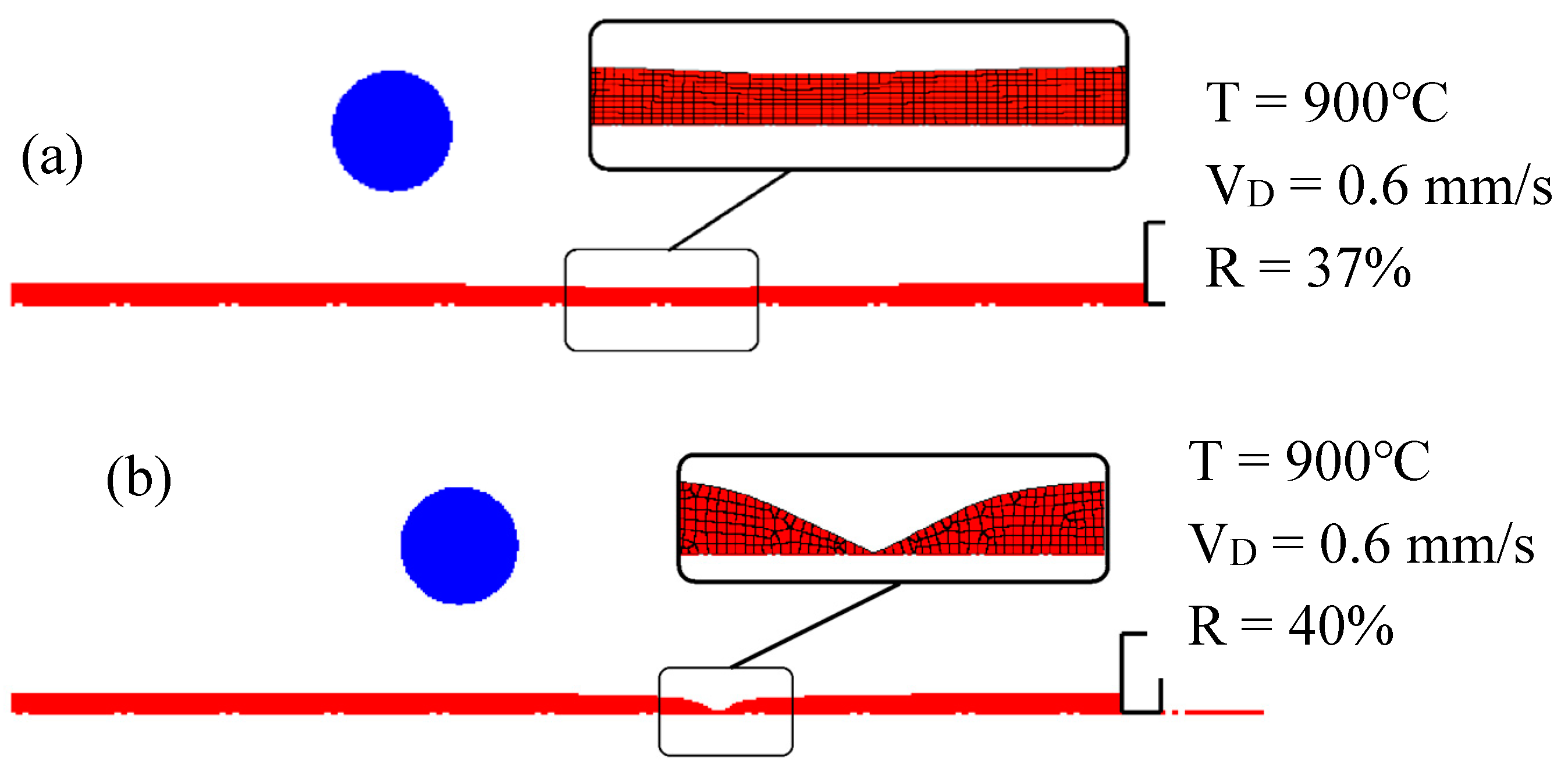
FE simulations with forming temperature of 900 °C and drawing speed of 0.6 mm/s were conducted. The profiles of the drawn wires at reductions of 37% and 40% are shown in Figure 12a,b, respectively. The profile shown in Figure 12a is regarded as a successful case and that shown in Figure 12b is regarded as a failure case. The area reduction of 37% obtained in Figure 12a is called the maximal reachable area reduction under the conditions of forming temperature of 900 °C and drawing speed of 0.6 mm/s. The effects of the drawing speed and forming temperature on the maximal reachable area reduction are discussed below.
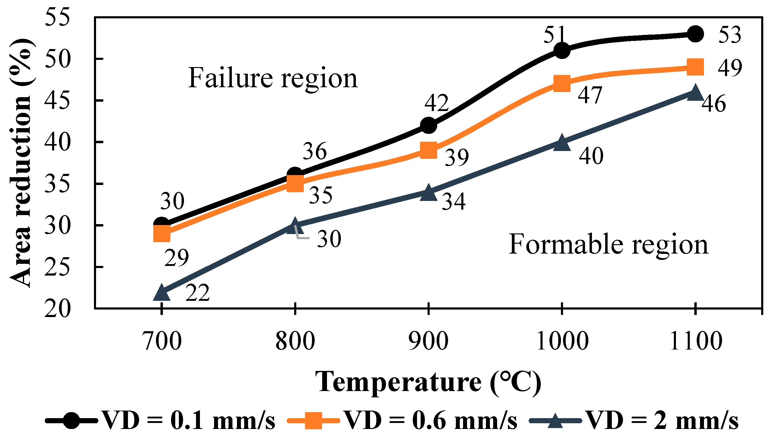
The simulation results of maximal reachable area reductions for different drawing speeds and different forming temperatures are shown in Figure 13. Clearly the maximal reachable area reduction increased as the forming temperature increased, because stainless steel wires at higher temperatures have smaller flow stresses and better flowability. On the other hand, the maximal reachable area reduction decreased as the drawing speed increased. A larger drawing speed resulted in poor flowability and accordingly a smaller reachable area reduction was obtained.
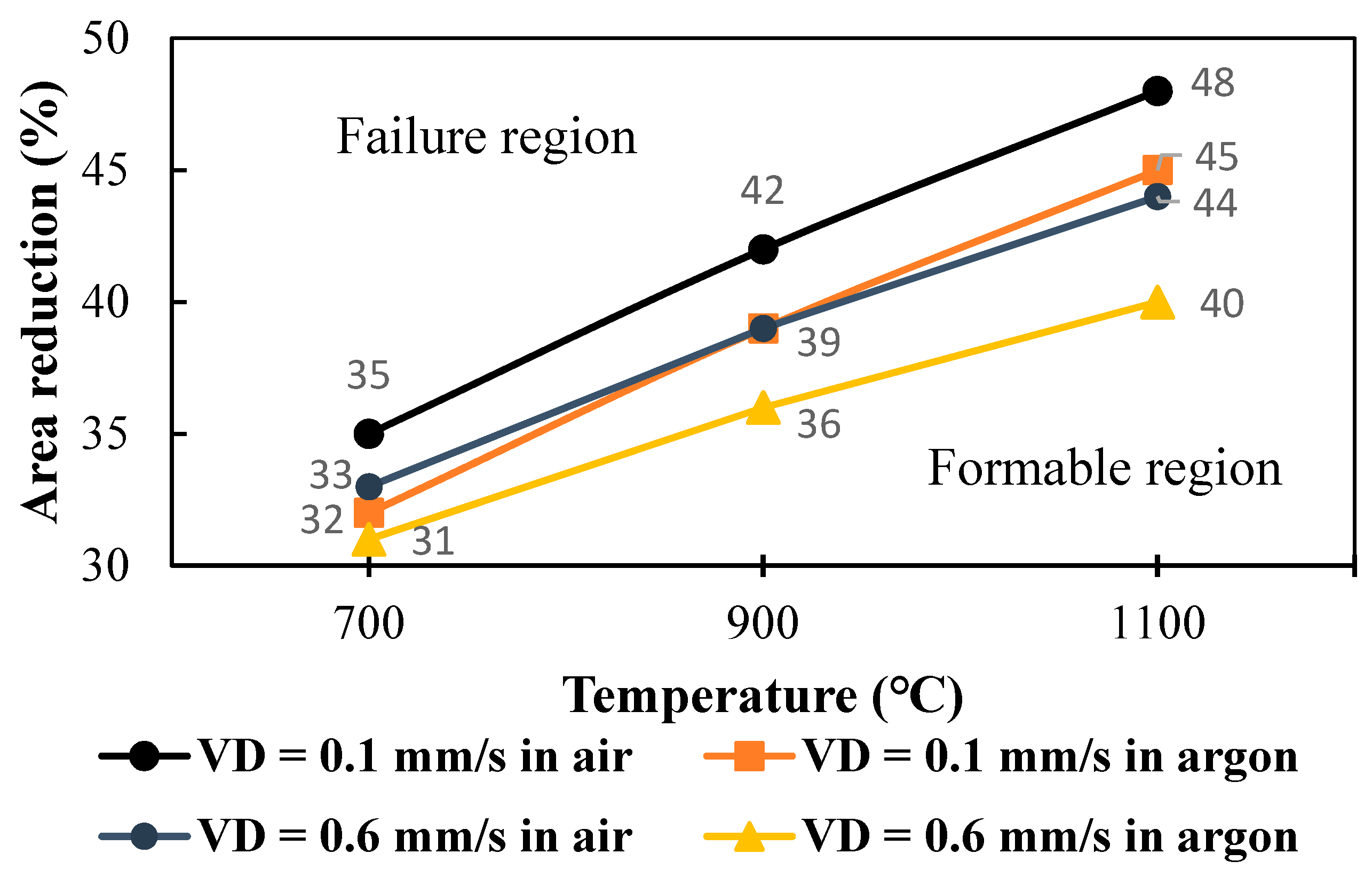
The experimental results of the maximal reachable area reduction in air and argon gas are shown in Figure 14. As in the cases in Figure 13 for the simulation results, a larger maximal reachable area reduction could be obtained at a higher forming temperature and at a lower drawing speed. The maximal reachable area reductions during drawing in air are larger than those in argon gas. That is because continuously pouring of argon gas into the chamber cools down the wire and reduce the flowability of the deformation region.
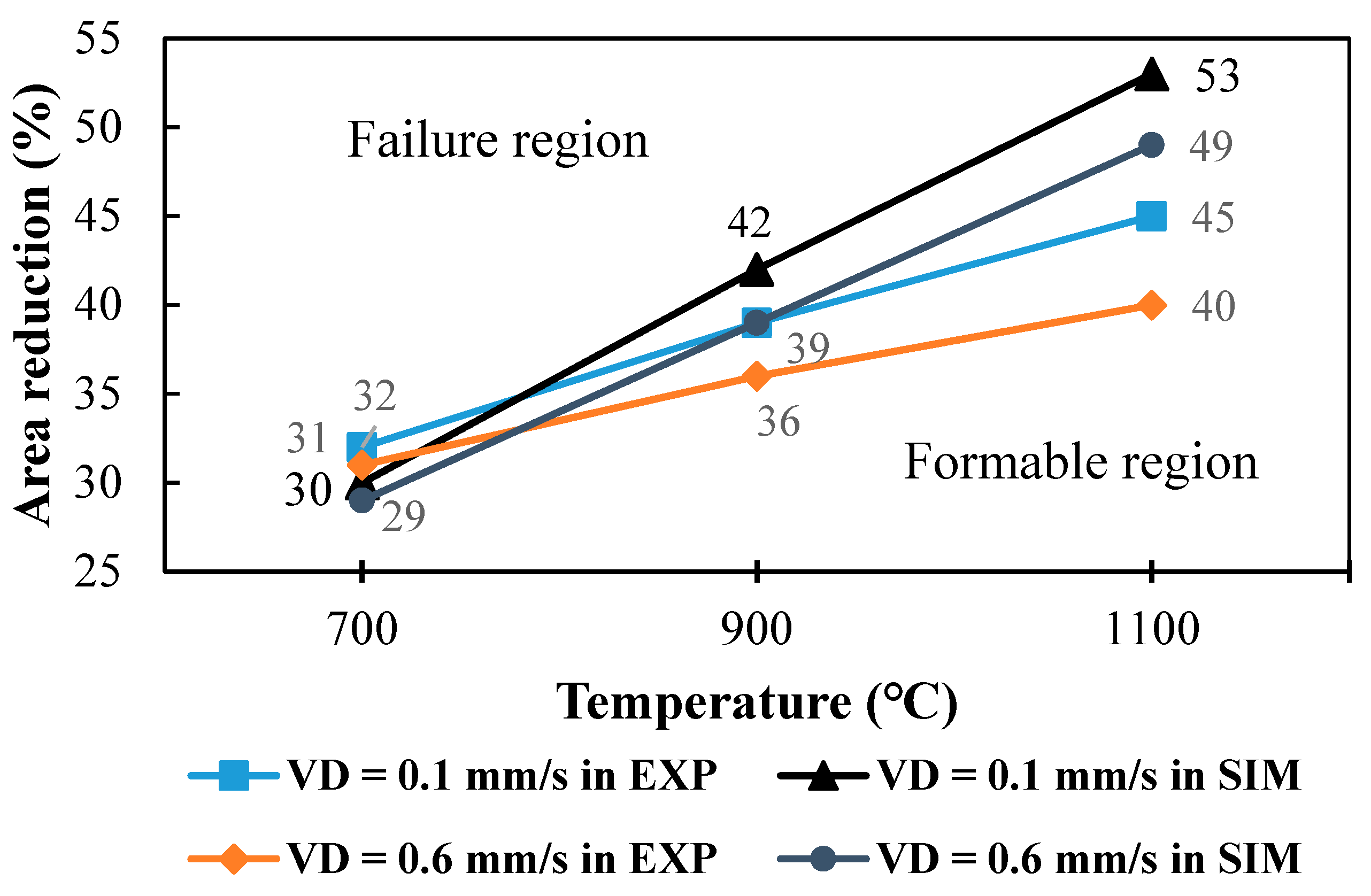
The comparisons of maximal reachable area reductions at drawing speeds of 0.1 and 0.6 mm/s during drawing in argon between simulations and experiments are shown in Figure 15. Generally the tendency of simulative maximal reachable area reduction was the same as that from experimental results. A bigger error between the simulative and experimental values at a higher temperature of 1100 °C was found. That was probably because of some discrepancy in the material flow stresses used in the FE simulations and the real stainless steel wires.

6. Conclusions

In this study, dieless drawing experiments on stainless steel SUS304 wires in air and argon gas were conducted using a self-developed dieless drawing machine. The effects of forming temperatures and the oxide layers on the mechanical properties of the drawn stainless steel SUS304 wires were discussed. The yield stress and UTS of the drawn wires decreased as the forming temperature increased. The yield stress and UTS of the drawn wires in air were slightly higher than those in argon gas, whereas the elongations of the drawn wires increased as the drawing temperature increased and the elongations in air were slightly smaller than those in argon gas. A finite element model considering the high frequency induction heating mode was used to conduct the formability analysis at different drawing speeds and forming temperatures during dieless drawing of stainless steel wires. A lower drawing speed and a higher forming temperature could raise the maximal reachable area reductions. The simulative maximal reachable area reductions at lower temperatures were quite coincident with the experimental results.

Author Contributions

Conceptualization, methodology, research supervision and writing—review and editing were conducted by Y.M.H. Simulation, experiments, validation and writing—original draft preparation were completed by H.H.L.

Funding

The authors would like to extend their thanks to the Ministry of Science and Technology of the Republic of China under Grant no. MOST 107-2221-E-110-038-MY3. The advice and financial support of MOST are gratefully acknowledged.

Acknowledgments

The authors would like to extend their thanks to the ministry of science and technology of the republic of china under grant no. most107-2221-e-110-038-my3. The advice and financial support of most are gratefully acknowledged.

Conflicts of Interest

The authors declare no conflict of interest.

References

  1. Weiss, V.; Kot, R. Dieless wire drawing with transformation plasticity. Wire J. 1969, 9, 182–189. [Google Scholar]
  2. Wicht, H.; Bouchaud, J. Nexus Market Analysis for MEMS and Microsystems III. MST News 2009, 5, 33. [Google Scholar]
  3. Furushima, T.; Manabe, K. Experimental and numerical study on deformation behavior in dieless drawing process of superplastic microtubes. J. Mater. Process. Technol. 2007, 191, 59–63. [Google Scholar] [CrossRef]
  4. Fortunier, R.; Sassoulas, H.; Momtheillet, F. A thermo-mechanical analysis of stability in dieless wire drawing. Int. J. Mech. Sci. 1997, 39, 615–627. [Google Scholar] [CrossRef]
  5. Wang, Z.T.; Zhang, S.H.; Xu, Y.; Luan, G.F.; Bai, G.R. Experiment study on the variation of wall thickness during dieless drawing of stainless steel tube. J. Mater. Process. Technol. 2002, 120, 90–93. [Google Scholar] [CrossRef]
  6. Wang, Z.T.; Luan, G.F.; Bai, G.R. Study of the deformation velocity field and drawing force during the dieless drawing of tube. J. Mater. Process. Technol. 1999, 94, 73–77. [Google Scholar] [CrossRef]
  7. Furushima, T.; Hirose, S.; Manabe, K. Effective temperature distribution and drawing speed control for stable dieless drawing process metal tube. J. Solid Mech. Mater. Eng. 2009, 3, 236–246. [Google Scholar] [CrossRef]
  8. Furushima, T.; Manabe, K. Experimental study on multi-pass dieless drawing process of superplastic Zn-22%Al alloy microtubes. J. Mater. Process. Technol. 2007, 187–188, 236–240. [Google Scholar] [CrossRef]
  9. Furushima, T.; Manabe, K. FE analysis of size effect on deformation and heat transfer behavior in microtube dieless drawing. J. Mater. Process. Technol. 2008, 201, 123–127. [Google Scholar] [CrossRef]
  10. Furushima, T.; Imagawa, Y.; Manabe, K.; Sakai, T. Effects of oxidation and surface roughening on drawing limit in dieless drawing process of SUS304 stainless steel microtubes. J. Mater. Process. Technol. 2015, 223, 186–192. [Google Scholar] [CrossRef]
  11. Furushima, T.; Imagawa, Y.; Furushima, S.; Manabe, K. Deformation profile in rotary laser dieless drawing process for metal microtubes. Procedia Eng. 2014, 81, 700–705. [Google Scholar] [CrossRef]
  12. Milenin, A. Rheology-based approach of design the dieless drawing processes. Arch. Civ. Mech. Eng. 2018, 18, 1309–1317. [Google Scholar] [CrossRef]
  13. Twohig, E.; Tiernan, P.; Tofail, S.A.M. Experimental study on dieless drawing of Nickel-Titanium alloy. J. Mech. Behav. Biomed. Mater. 2012, 8, 8–20. [Google Scholar] [CrossRef] [PubMed]
  14. Naughton, M.D.; Tiernan, P. Requirements of a dieless wire drawing system. J. Mater. Process. Technol. 2007, 191, 310–313. [Google Scholar] [CrossRef]
  15. Tiernan, P.; Carolan, R.; Twohig, E.; Tofail, S.A.M. Design and development of a novel load-control dieless rod drawing system. CIRP J. Manuf. Sci. Technol. 2011, 4, 110–117. [Google Scholar] [CrossRef]
  16. Supriadi, S.; Manabe, K. Enhancement of dimensional accuracy of dieless tube-drawing process with vision-based fuzzy control. J. Mater. Process. Technol. 2013, 213, 905–912. [Google Scholar] [CrossRef]
  17. Tiernan, P. Dieless drawing of bars, rods, tubes, and wires. Compre. Mater. Process. 2014, 3, 149–157. [Google Scholar]
  18. Sekiguchi, H.; Kobatake, K.; Osakada, K. A fundamental study on dieless drawing. In Proceedings of the Fifteenth International Machine Tool Design and Research Conference; Tobias, S.A., Koenigsberger, F., Eds.; Palgrave: London, UK, 1975; pp. 539–544. [Google Scholar]
  19. Hwang, Y.M.; Kuo, T.Y. Dieless drawing of stainless steel tubes. Int. J. Adv. Manuf. Technol. 2013, 68, 1311–1316. [Google Scholar] [CrossRef]
  20. Qin, F.; Liu, X.F.; Mao, H.E. The thickness distribution of oxidation film on tapered pipe surface in dieless drawing. Inter. J. Corros. 2011, 2011, 615197. [Google Scholar] [CrossRef]
Figure 1. Schematic of a backward non-continuous dieless wire drawing process.
Metals 09 00828 g001
Figure 2. Layout of self-developed dieless drawing machine.
Metals 09 00828 g002
Figure 3. Schematic of self-designed argon gas chamber.
Metals 09 00828 g003
Figure 4. Appearance of stainless steel wire surfaces under different forming conditions.
Metals 09 00828 g004
Figure 5. Engineering stress-strain curves at different forming temperatures.
Metals 09 00828 g005
Figure 6. Comparisons of yield stresses of drawn wires in air and argon gas.
Metals 09 00828 g006
Figure 7. Comparisons of ultimate tensile strength of drawn wires in air and argon gas.
Metals 09 00828 g007
Figure 8. Comparisons of elongation of drawn wires in air and argon gas.
Metals 09 00828 g008
Figure 9. Flow stress curves of SUS304 at ε ˙ = 0.25.
Metals 09 00828 g009
Figure 10. (a) Configuration of wire and heating coil used in DEFORM 2D, (b) 3D perspective view.
Metals 09 00828 g010
Figure 11. (a) Relationships between forming temperature variation and input power, (b) Relationships between heating speed, forming temperature and drawing speed.
Metals 09 00828 g011
Figure 12. Profiles of drawn wires at different reductions. (a) Successful case, (b) Failure case.
Metals 09 00828 g012
Figure 13. Simulative maximal reachable area reductions at different temperatures and drawing speeds.
Metals 09 00828 g013
Figure 14. Experimental maximal reachable area reductions in air and argon gas.
Metals 09 00828 g014
Figure 15. Comparisons of maximal reachable area reduction between simulations and experiments.
Metals 09 00828 g015
Table 1. Forming conditions for dieless wire drawing experiments.
ParametersValues
MaterialSUS304
AtmosphereAir, Argon gas
Forming temperature, T [°C]700, 800, 900, 1000, 1100
Area reduction, R [%]30
Drawing speed, VD [mm/s]0.6
Heating coil speed, VH [mm/s]1.4
Workpiece wire diameter, D0 [mm]1
Heating coil loop inner diameter, DC [mm]5.5
Heating coil wire diameter, dC [mm]3
Table 2. Parameters used in formability analysis.
ParametersValues
Diameter of wire, D0 [mm]1
Length of wire, WL [mm]60
Wire mesh layers in radius, WL7
Wire mesh number, WN5500
Coil mesh number, CN4130
Coil loop inner diameter, DC [mm]5.5
Coil wire diameter, dC [mm]3
Current frequency, f [KHz]1000