Abstract
Selective laser surface melting, which brings together the bionic theory and the laser process, is an effective way to enhance the thermal fatigue behavior of materials. In this study, in order to examine the relationship between the mechanical properties and thermal fatigue behavior of materials processed by selective laser surface melting, the tensile properties at room temperature and elevated temperature of treated specimens and untreated specimens after different numbers of thermal fatigue cycles were investigated and compared. Moreover, the microstructure evolution and the microhardness of the laser-affected zone were investigated after different numbers of thermal fatigue cycles. The results show that microhardness of the laser-melted zone gradually decreases with an increasing number of thermal fatigue cycles; the number of thermal fatigue cycles has little effect on the grain size in the laser-melted zone, and the percentage of low-angle grain boundaries decreases with an increasing number of thermal fatigue cycles. The strength of specimens gradually decreases, whereas the fracture elongation gradually increases with an increasing number of thermal fatigue cycles at room temperature and elevated temperature. In addition, the stress distribution on the specimen surface during tensile test was investigated using the finite element method, and the results indicate that the stress transfer exists between the laser-affected zone and the untreated zone.
1. Introduction
H13 tool steel, which is mainly comprised of Cr-Mo-V element in different percentages, belongs to the chromium hot-work tool steel. It has a combination of properties such as toughness, strength and ductility, and thermal conductivity [1,2]. Therefore, H13 tool steel has been applied widely in casting, extrusion, and forging. However, hot-work dies usually suffer from severe static/cyclic load such as impulsive load and thermal stress at elevated temperatures [3,4]. These severe service conditions often result in erosion, thermal fatigue, and wear in the surfaces of dies. As the damage occurs in the prime location of dies, the die has to be repaired or replaced, leading to significant economic loss. Therefore, improving the service life of hot-work dies has been a priority in the metalworking industry. The surface properties of hot-work dies have been improved by many methods such as heat treatment [5,6,7,8,9,10], adding alloy elements [11,12,13], and surface modification [14,15,16,17,18,19,20,21].
Among the different failure mechanisms, thermal fatigue, which is responsible for 70% of failures, is one of the main failure mechanisms of die-casting dies [11]. In recent years, the bionic laser surface treatment method has been carried out to enhance the thermal fatigue behavior of hot-work tool steel. This new method combines the laser surface processing with the bionic theory, and it is a selective process on the surface of materials. This method is inspired by living creatures, such as the shell and wing of insects as well as leaves, which have multifunctional structures for adapting to the natural environment. The nacreous layer of shell is made up of aragonite and organic layers. The nacreous layer is an alternating structure of soft (organic layer) and hard (aragonite layer) material. As the crack propagates in the nacreous layer, it frequently deflects at the boundary between the aragonite and organic layers [22]. Therefore, this nacreous layer exhibits superior mechanical properties. The wing of an insect and a leaf also has specific morphologies, structures, and materials. The veins serve as the hard phase on the wings and leaves and provide essential mechanical support and protection. Therefore, the wing of insects and leaves are not easily destroyed by stormy weather. The laser-affected zone, allowing grain refinement, microstructural changes, and dissolution of inclusion and precipitates [23,24], serves as the hard phase. In contrast, the matrix serves as the soft phase. Therefore, the alternating hard and soft structure is formed by the selective laser surface melting, which is similar to the structure of the shell and wing of insects and leaves. Zhou et al. [25] investigated the hot cracking resistance of 3Cr2W8V hot-work tool steel with different nonsmooth surface shapes processed by laser surface melting and proposed that the hot cracking resistance of a nonsmooth specimen is superior to the smooth specimen. Zhou et al. [26] and Zhang et al. [27] reported that the spacing and size of the laser-affected zone are important factors affecting the thermal fatigue behavior of a nonsmooth specimen. Cong et al. [28,29,30] used the selective laser surface melting and alloying to repair hot cracks on H13 hot-work tool steel and suggested that the repaired specimens processed by selective laser treatment can increase the thermal fatigue life. Jia et al. [31] and Chen et al. [32] reported that the service life of the die-casting part is improved by selective laser treatment during practical application. The results of the experimental studies and practical applications show that H13 hot-work tool steel with the alternating hard and soft structure processed by the selective laser surface melting can increase the thermal fatigue behavior. However, the mechanical properties, which have a tight connection with the thermal fatigue behavior, do not clarify an improved mechanism of thermal fatigue behavior after thermal fatigue.
In this work, microstructure evolution and microhardness of the laser-affected zone and the matrix were investigated and compared after different numbers of thermal fatigue cycles. Tensile properties after different numbers of thermal fatigue cycles were investigated at room temperature and elevated temperature. Fracture morphologies of the tensile specimens were also studied. In addition, the finite element as an attempt, was adopted to understand the stress distribution of the specimen during tensile testing.
2. Materials and Methods
The substrate for laser processing was an as-received H13 hot-work tool steel and its chemical composition is given in Table 1.

Table 1.
Chemical compositions of as-received H13 hot-work tool steel (wt%).
A Nd:YAG laser was utilized for laser surface melting (LSM) and the LSM processing parameters are listed in Table 2. A manipulator (Motoman, MH6, Kyushu, Japan) was linked to the YAG laser, which controlled the machining precision at ±0.08 mm. In addition, argon gas was utilized to prevent from oxidizing during the LSM processing.
Table 2.
Laser surface melting parameters.
The diagram of tensile testing specimens is given in Figure 1. The tensile testing specimens were placed in the thermal fatigue testing apparatus through the 1.6 mm radius round hole. The sketch of the thermal fatigue testing machine is depicted in Figure 2. The thermal fatigue testing machine set the testing temperature, holding and cooling time, and automatically keep an account of the number of thermal cycles by the controlling tank. The stiff load frame installed a number of specimens, which provided a good contrast under the same testing condition. A complete time of thermal cycle was 82 s. A high-temperature electric resistance furnace was used to heat the specimens for 70 s to 650 ± 5 °C, and running water was used to cool the specimens for 6 s to 25 ± 5 °C, and 6 s for the specimens shift between the heating furnace and the running water. For tensile testing at room temperature (RT) and elevated temperature (650 °C), the specimens were removed at every 400 thermal cycles until 1200 thermal cycles.
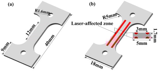
Figure 1.
The schematic illustration of testing specimens: (a) untreated specimen and (b) laser surface melting (LSM-) treated specimen.
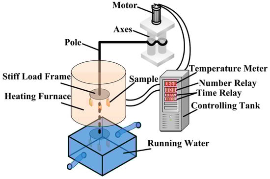
Figure 2.
The schematic illustration of thermal fatigue testing rig.
An X-ray diffraction instrument (Shimadzu, XRD-6100, Kyoto, Japan) was utilized to analyze the phase compositions in specimens. The microstructures and fracture morphologies in the laser-affected zone and the matrix at different numbers of thermal cycles were observed using a scanning electron microscopy (Jeol, JSM-7500F, Kyoto, Japan). Electron backscatter diffraction (Oxford Instrument, NordlysMax2, Oxford, UK) was used to study the grain boundary misorientation. The HKL Channel 5 software package was utilized to analyze the Electron backscatter diffraction (EBSD) data. Microhardness testing was carried out by a Vickers hardness tester (Falcon, 600, Eindhoven, The Netherlands). A stereomicroscope (Olympus, SZ61-SET, Kyoto, Japan) was used to assess the thermal fatigue crack on the surface of each specimen. Each specimen was cleaned using a NaOH solution, and then alcohol was used to remove oxide scales on the surface after the thermal fatigue testing. The thermal fatigue crack was not observed on the surface of each specimen after 1200 thermal cycles. In addition, ANSYS workbench was used to analyze the stress distribution on the surface of sample processed by the LSM during the tensile test and the wear test. The residual stress caused by laser processing was ignored during the finite element method (FEM). The finite element modeling consisted of two volumes (substrate and laser treated zone). The two volumes were glued using Booleans before meshing. The meshing sizes of the substrate and laser treated zone were 0.25 mm and 0.05 mm, respectively. A static structure mode was utilized for analyzing the stress condition. The load conditions in the FEM were set according to the test conditions. The physical parameters of the specimens used in the FEM are listed in Table 3.
Table 3.
The parameters used in the finite element method (FEM).
3. Results and Discussion
3.1. Phase and Microstructure Analysis
Figure 3 shows the X-ray diffraction (XRD) patterns of the as-received H13 steel and laser-affected zone of LSM-treated specimen. According to the XRD patterns, the as-received specimen shows α-Fe (110), (200), (211), (220), and (310) phases as shown in Figure 3. The original phase of the as-received specimen is ferrite due to annealing. As shown in Figure 3, the peaks are (211) martensite and α-Fe (110), (200), (211), (220), and (310) phases which are in agreement with the data by previous researchers [34], and γ-Fe peaks are also detected in the laser-affected zone of LSM-treated specimen. The reduction of α-Fe peaks intensity, which results from decreasing phase crystallinity, is observed in the laser-affected zone as compared with as-received H13 steel. The decreasing phase crystallinity indicates the undercooled austenite transformation [34]. At high cooling rates during laser processing, austenite may transform martensite. Therefore, the laser-affected zone contains a part of martensite and retained austenite.
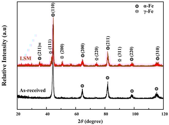
Figure 3.
X-ray diffraction (XRD) patterns of as-received H13 steel and laser-affected zone.
Figure 4 shows the morphology and microstructure of the LSM-treated specimen. The transverse section is shown in Figure 4a. The interface of laser-affected zone and matrix is metallurgical bonding. The width and depth of the laser-affected zone are ~900 μm and ~500 μm, respectively. Owing to the rapid heating and cooling effects of the laser surface melting, the laser-melted zone achieves a remarkable microstructural refinement as compared with the matrix, which is rough and nonuniform carbide particles and crystal grains, as shown in Figure 4b,d. The columnar structure is at the bottom of the laser-melted zone, because solidification usually starts by the epitaxial growth on the matrix [35], and phase transformation and carbide coarsening occur in the transition zone, as shown in Figure 4c.
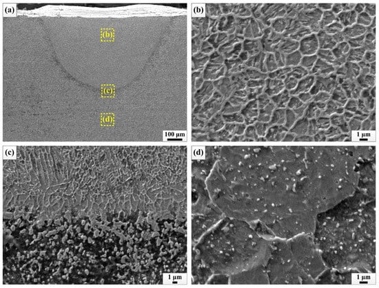
Figure 4.
Morphology and microstructure: (a) cross-section of LSM-treated specimen, microstructure of (b) laser-melted zone, (c) interface of laser-melted zone and transition zone, and (d) matrix.
3.2. Microhardness and Microstructural Evolution after Different Numbers of Thermal Fatigue Cycles
Figure 5 presents the microhardness profile as a function of depth and width measured on the transverse sectional of the LSM-treated specimen after different numbers of thermal fatigue cycles. Before thermal fatigue testing (0 cycle), microstructural refinement and the formation of martensite in the laser-melted zone increase the hardness, and the average microhardness values of the laser-melted zone and matrix are ~675 HV and ~286 HV. The microhardness in the laser-melted zone gradually decreases with increasing thermal fatigue cycles, because the thermal fatigue is an accumulation of tempering which gives rise to microstructural evolution. With an increasing number of thermal fatigue cycles, martensite in the laser-melted zone gradually transforms to ferrite when tempering occurs [36], decreasing the microhardness. Figure 6 shows the microstructural evolution of the laser-melted zone with an increasing number of thermal fatigue cycles. The grains boundaries gradually dissolve, especially for 1200 cycles. Further research based on the EBSD shows that the grain size is insensitive to thermal fatigue cycles, as shown in Figure 7. The crystallography orientation of the grains is random before and after thermal fatigue testing. In addition, the distribution percentage of low-angle grain boundaries (2° < LAGBs < 15°) is higher than those of the high-angle grain boundaries (HAGBs > 15°). The LAGBs are attributed to the fine microstructure, resulting from the rapid solidification during laser processing and the HAGBs directly relate with the recrystallized of grains [37]. The large number of LAGBs significantly impedes the movement of dislocations [38] and is attributed to the higher microhardness before thermal fatigue testing. Figure 8 shows the microstructural evolution of the matrix with an increasing number of thermal fatigue cycles. Carbides gradually coarsen in the matrix which can be ascribed to the precipitation of alloy carbides during the process of thermal cycling [39,40].
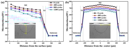
Figure 5.
Microhardness profile along the transverse sectional of the LSM-treated specimen after different numbers of thermal fatigue cycles: (a) the vertical direction and (b) the horizontal direction.
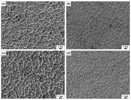
Figure 6.
Microstructure evolution of laser-melted zone after different numbers of thermal fatigue cycles: (a) 0 cycle, (b) 400 cycles, (c) 800 cycles, and (d) 1200 cycles.
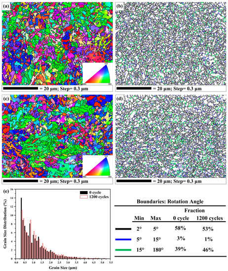
Figure 7.
Electron backscatter diffraction (EBSD) orientation map and grain boundary misorientation map of the specimens before and after thermal fatigue test: (a,b) 0 cycle, (c,d) 1200 cycles, and (e) grain size distribution.
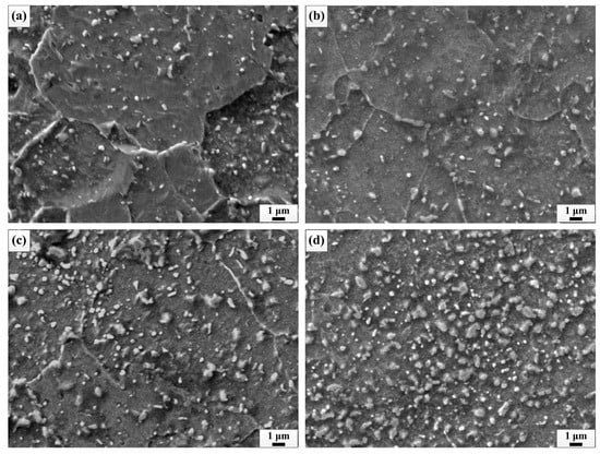
Figure 8.
Microstructural evolution of matrix after different numbers of thermal fatigue cycles: (a) 0 cycle, (b) 400 cycles, (c) 800 cycles, and (d) 1200 cycles.
3.3. Tensile Properties at Room Temperature and Elevated Temperature after Different Numbers of Thermal Fatigue Cycles
Figure 9 and Figure 10 represent the effect of thermal fatigue cycles on the tensile properties of the LSM-treated specimen and untreated specimen at RT and 650 °C, respectively. Before thermal fatigue testing, as shown in Figure 9a and Figure 10a, the strength of the specimen increased while the fracture elongation decreased by LSM at RT and 650 °C. The changes in the tensile properties of the LSM-treated specimen are linked with microstructural refinement, the formation of martensite, and improved microhardness in the laser-melted zone. Figure 11 shows the change of strength and elongation as a function of the thermal fatigue cycles at RT and 650 °C. The strength of specimens gradually decreases while the fracture elongation gradually increases with an increasing number of thermal fatigue cycles. On the other hand, the strength of the LSM-treated specimen is still higher than that of the untreated specimen with an increasing number of thermal fatigue cycles. This can be ascribed to higher microhardness and finer microstructure of the laser-affected zone as compared with the untreated specimen after thermal fatigue testing. In addition, stress transfer is considered an important mechanism for improving the strength of the material processed by the LSM treatment [41,42]. The stress transfer between the soft phase and the hard phase contributes to the higher strength of materials. In order to explain the phenomenon of stress transfer, the FEM as an attempt was used to understand the stress distribution of the specimen processed by LSM. The results of the FEM analysis under the experimental condition are shown in Figure 12. The maximum stress is observed in the laser-treated zone, while the stress in the untreated zone of LSM-treated specimen is lower than that of the untreated specimen. As a consequence, the untreated zone carries more stress than that in the untreated specimen, enhancing the strength of the LSM-treated specimen. The greater strength of the material accounts for its better resistance to crack initiation [5]. Therefore, the LSM-treated specimen exhibits a better thermal fatigue behavior as compared with the untreated specimen.
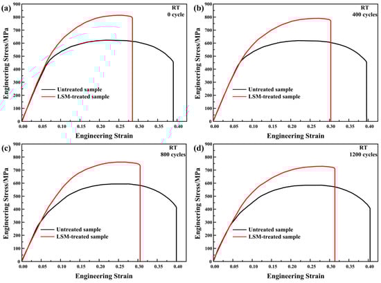
Figure 9.
Stress-strain curves of LSM-treated specimen and untreated specimen at room temperature (RT) and for thermal fatigue cycles equal to (a) 0 cycle, (b) 400 cycles, (c) 800 cycles, and (d) 1200cycles.
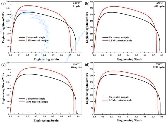
Figure 10.
Stress-strain curves of LSM-treated specimen and untreated specimen at 650 °C and for thermal fatigue cycles equal to (a) 0 cycle, (b) 400 cycles, (c) 800 cycles, and (d) 1200 cycles.
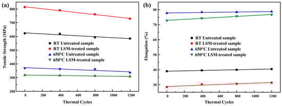
Figure 11.
Strength (a) and elongation (b) of LSM-treated specimen and untreated specimen versus thermal fatigue cycles.
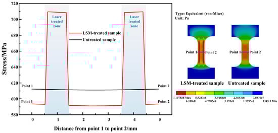
Figure 12.
Stress distributions of specimens and stress value from point 1 to point 2 during tensile test.
3.4. Fracture Morphologies
The fracture surfaces of the LSM-treated specimen after thermal fatigue testing are given in Figure 13 and Figure 14. The fracture characteristics of the laser-melted zone and matrix are the ductile mode. An increased number of thermal fatigue cycles and elevated temperature tensile increase the size of dimples in the melted zone and the matrix. The increased size of dimples demonstrates that the mechanical strength decreases and the ductility increases.
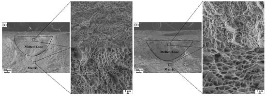
Figure 13.
Fracture morphologies of LSM-treated specimen after 400 thermal cycles: (a) RT and (b) 650 °C.
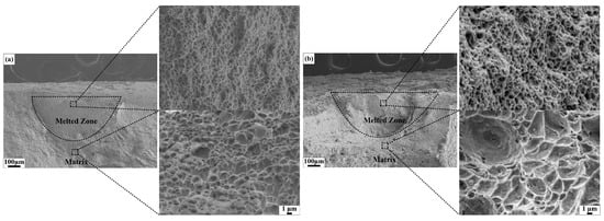
Figure 14.
Fracture morphologies of LSM-treated specimen after 1200 thermal cycles: (a) RT and (b) 650 °C.
4. Conclusions
The thermal fatigue behavior of H13 tool steel is improved by selective laser surface melting treated. The reason for the improved thermal fatigue behavior was investigated by comparing the microstructure and mechanical properties between the treated specimens and untreated specimen. With an increasing number of thermal fatigue cycles, the carbides gradually coarsen in the matrix, whereas, the grain size in the laser-melted zone is insensitive to thermal fatigue cycles. The percentage of LAGBs in the laser-melted zone decreases, thus decreasing the microhardness. The strength of the LSM-treated specimen gradually decreases, whereas, the fracture elongation gradually increases at room temperature and elevated temperature. In addition, because of higher microhardness, finer microstructure, and stress transfer, the strength of the LSM-treated specimen is still higher than that of the untreated specimen. Therefore, the LSM-treated specimen exhibits better thermal fatigue behavior as compared with the untreated specimen.
Author Contributions
Conceptualization, C.M.; software, C.M. and C.W.; validation, C.M., J.L., and C.W.; formal analysis, X.W.; investigation, C.M., J.L., and R.C.; resources, C.M.; writing—original draft preparation, C.M.; writing—review and editing, C.M. and X.W.; supervision, C.M.; project administration, C.M.; and funding acquisition, C.M.
Funding
This research was funded by the National Natural Science Foundation for Youths (No. 51805235), the Natural Science Foundation of Liaoning Province (No. 20170540421) and the PhD research startup fund of Liaoning Technical University (No. 16-1009).
Conflicts of Interest
The authors declare no conflict of interest.
References
- Birol, Y. Response to thermal cycling of duplex-coated hot work tool steels at elevated temperatures. Mater. Sci. Eng. A 2011, 528, 8402–8409. [Google Scholar] [CrossRef]
- Duan, Z.X.; Pei, W.; Gong, X.B.; Chen, H. Superplasticity of Annealed H13 Steel. Materials 2017, 10, 870. [Google Scholar] [CrossRef] [PubMed]
- Salem, M.; Roux, S.L.; Dour, G.; Lamesle, P.; Choquet, K.; Rézaï-Aria, F. Effect of aluminizing and oxidation on the thermal fatigue damage of hot work tool steels for high pressure die casting applications. Int. J. Fatigue 2019, 119, 126–138. [Google Scholar] [CrossRef]
- Hao, G.C.; Liu, Z.Q.; Liang, X.L.; Zhao, J.F. Influences of TiAlN Coating on Cutting Temperature during Orthogonal Machining H13 Hardened Steel. Coatings 2019, 9, 355. [Google Scholar] [CrossRef]
- Sjöström, J.; Bergström, J. Thermal fatigue testing of chromium martensitic hot-work tool steel after different austenitizing treatments. J. Mater. Process. Technol. 2004, 153, 1089–1096. [Google Scholar] [CrossRef]
- Ning, A.; Mao, W.; Chen, X.; Guo, H.; Guo, J. Precipitation Behavior of Carbides in H13 Hot Work Die Steel and Its Strengthening during Tempering. Metals 2017, 7, 70. [Google Scholar] [CrossRef]
- Demir, H.; Gündüz, S.; Erden, M.A. Influence of the heat treatment on the microstructure and machinability of AISI H13 hot work tool steel. Int. J Adv. Manuf. Tech. 2018, 95, 2951–2958. [Google Scholar] [CrossRef]
- Zhang, Y.; Li, J.; Shi, C.B.; Qi, Y.F.; Zhu, Q.T. Effect of Heat Treatment on the Microstructure and Mechanical Properties of Nitrogen-Alloyed High-Mn Austenitic Hot Work Die Steel. Metals 2017, 7, 94. [Google Scholar] [CrossRef]
- Junker, D.; Hentschel, O.; Schmidt, M.; Merklein, M. Investigation of Heat Treatment Strategies for Additively-Manufactured Tools of X37CrMoV5-1. Metals 2018, 8, 854. [Google Scholar] [CrossRef]
- Çiçek, A.; Kara, F.; Kıvak, T.; Ekici, E.; Uygur, İ. Effects of Deep Cryogenic Treatment on the Wear Resistance and Mechanical Properties of AISI H13 Hot-Work Tool Steel. J. Mater. Eng. Perform. 2015, 24, 4431–4439. [Google Scholar] [CrossRef]
- Jiang, Q.C.; Zhao, X.M.; Qiu, F.; Ma, T.N.; Zhao, Q.L. The Relationship Between Oxidation and Thermal Fatigue of Martensitic Hot-Work Die Steels. Acta. Metall. Sin Engl. 2018, 31, 692–698. [Google Scholar] [CrossRef]
- Kheirandish, S.; Noorian, A. Effect of Niobium on Microstructure of Cast AISI H13 Hot Work Tool Steel. J. Iron Steel Res. Int. 2008, 15, 61–66. [Google Scholar] [CrossRef]
- Zhou, J.; Ma, D.S.; Chi, H.X.; Chen, Z.Z.; Li, X.Y. Microstructure and Properties of Hot Working Die Steel H13MOD. J. Iron Steel Res. Int. 2013, 20, 117–125. [Google Scholar] [CrossRef]
- Birol, Y.; Isler, D. Abrasive wear performance of AlCrN-coated hot work tool steel at elevated temperatures under three-body regime. Wear 2011, 270, 281–286. [Google Scholar] [CrossRef]
- Norhafzan, B.; Aqida, S.N.; Chikarakara, E.; Brabazon, D. Surface modification of AISI H13 tool steel by laser cladding with NiTi powder. Appl. Phys. A 2016, 122, 384–390. [Google Scholar] [CrossRef]
- Aqida, S.N.; Calosso, F.; Brabazon, D.; Naher, S.; Rosso, M. Thermal fatigue properties of laser treated steels. Int. J. Mater. Form. 2010, 3, 797–800. [Google Scholar] [CrossRef]
- Fauzun, F.; Aqida, S.N.; Naher, S.; Brabazon, D.; Calosso, F.; Rosso, M. Effects of Thermal Fatigue on Laser Modified H13 Die Steel. J. Mech. Sci. Technol. 2014, 6, 975–980. [Google Scholar] [CrossRef]
- Ley, N.; Joshi, S.S.; Zhang, B.Z.; Ho, Y.H.; Dahotre, N.B.; Young, M.L. Laser coating of a CrMoTaWZr complex concentrated alloy onto a H13 tool steel die head. Surf. Coat. Technol. 2018, 384, 150–158. [Google Scholar] [CrossRef]
- Orečný, M.; Buršák, M.; Šebek, M.; Falat, L. Influence of Hardness, Matrix and Carbides in Combination with Nitridation on Abrasive Wear Resistance of X210Cr12 Tool Steel. Metals 2016, 6, 236. [Google Scholar] [CrossRef]
- Jose, M.P.; German, F.R.; Edinei, L.J.; Pietro, S.; Yassmin, S.A.; Marcelo, M.M.; Carlos, B.; Stephen, V. Tribological and Wear Performance of Nanocomposite PVD Hard Coatings Deposited on Aluminum Die Casting Tool. Materials 2018, 11, 358. [Google Scholar] [CrossRef]
- Wang, G.Y.; Zhang, J.Z.; Shu, R.Y.; Yang, S. High temperature wear resistance and thermal fatigue behavior of Stellite-6/WC coatings produced by laser cladding with Co-coated WC powder. Int. J. Refract. Met. 2019, 81, 63–70. [Google Scholar] [CrossRef]
- Kamat, S.; Su, X.; Ballarini, R.; Henuer, A.H. Structural basis for the fracture toughness of the shell of the conth Strombus gigas. Nature 2000, 405, 1036–1040. [Google Scholar] [CrossRef] [PubMed]
- Tu, J.; Zhou, K.F.; Zhou, Z.M.; Huang, C.; Tang, H.L. Microstructural characteristics of cobalt treated by high-speed laser surface melting under high power. Mater. Charact. 2017, 128, 63–67. [Google Scholar] [CrossRef]
- Park, J.; Han, H.S.; Park, J.; Seo, H.; Edwards, J.; Kim, Y.C.; Ok, M.R.; Seok, H.K.; Jeon, H. Corrosion behavior of biodegradable Mg-based alloys via femtosecond laser surface melting. Appl. Surf. Sci. 2018, 448, 424–434. [Google Scholar] [CrossRef]
- Zhou, H.; Cao, Y.; Zhang, Z.H.; Ren, L.Q.; Li, X.Z. Thermal fatigue behavior of 3Cr2W8V die steel with biomimetic non-smooth surface. Mater. Sci. Eng. A 2006, 433, 144–148. [Google Scholar] [CrossRef]
- Zhou, H.; Zhang, Z.H.; Ren, L.Q.; Song, Q.F.; Chen, L. Thermal fatigue behavior of medium carbon steel with striated non-smooth surface. Surf. Coat. Technol. 2006, 200, 6758–6764. [Google Scholar] [CrossRef]
- Zhang, Z.H.; Zhou, H.; Ren, L.Q.; Tong, X.; Shan, H.Y.; Liu, L. Effect of units in different sizes on thermal fatigue behavior of 3Cr2W8V die steel with biomimetic non-smooth surface. Int. J. Fatigue 2009, 31, 468–475. [Google Scholar] [CrossRef]
- Cong, D.L.; Zhou, H.; Ren, Z.A.; Zhang, Z.H.; Zhang, H.F.; Meng, C.; Wang, C.W. The thermal fatigue resistance of H13 steel repaired by a biomimetic laser remelting process. Mater. Design 2014, 55, 597–604. [Google Scholar] [CrossRef]
- Cong, D.L.; Zhou, H.; Ren, Z.A.; Zhang, Z.H.; Zhang, H.F.; Ren, L.Q.; Meng, C.; Wang, C.W. Thermal fatigue resistance of hot work die steel repaired by partial laser surface remelting and alloying process. Opt. Laser. Eng. 2014, 54, 55–61. [Google Scholar] [CrossRef]
- Cong, D.L.; Li, Z.S.; He, Q.B.; Chen, D.J.; Chen, H.B.; Yang, J.Z.; Zhang, P.; Zhou, H. Effect of unit size on thermal fatigue behavior of hot work steel repaired by a biomimetic laser remelting process. Opt. Laser Technol. 2018, 98, 205–213. [Google Scholar] [CrossRef]
- Jia, Z.X.; Li, J.Q.; Liu, L.J.; Liu, Y.W.; Wang, Y.Q.; Li, H.L. Influence and application of laser parameters on unit of H13 steel by laser remelting process. Int. J. Adv. Manuf. Technol. 2015, 79, 551–568. [Google Scholar] [CrossRef]
- Chen, L.Q.; Liu, L.J.; Jia, Z.X.; Li, J.Q.; Wang, Y.Q.; Hu, N.B. Method for improvement of die-casting die: Combination use of CAE and biomimetic laser process. Int. J. Adv. Manuf. Technol. 2013, 68, 2841–2848. [Google Scholar] [CrossRef]
- Gu, S.T.; Chai, G.Z.; Wu, H.P.; Bao, Y.M. Characterization of local mechanical properties of laser-cladding H13-TiC composite coatings using nanoindentation and finite element analysis. Mater. Design 2012, 39, 72–80. [Google Scholar] [CrossRef]
- Aqida, S.N.; Brabazon, D.; Naher, S. An investigation of phase transformation and crystallinity in laser surface modified H13 steel. Appl. Phys. A 2013, 110, 673–678. [Google Scholar] [CrossRef]
- Kwok, C.T. Laser Surface Modification of Alloys for Corrosion and Erosion Resistance, 1st ed.; Woodhead Publishing Limited: Oxford, UK, 2017; p. 53. [Google Scholar]
- Wang, M.; Li, W.; Wu, Y.; Li, S.; Cai, C.; Wen, S.F.; Wei, Q.S.; Shi, Y.S.; Ye, F.Y.; Chen, Z.P. High-Temperature Properties and Microstructural Stability of the AISI H13 Hot-Work Tool Steel Processed by Selective Laser Melting. Metall. Mater. Trans. B 2019, 50, 531–542. [Google Scholar] [CrossRef]
- Chen, H.Y.; Gu, D.D.; Dai, D.H.; Xia, M.J.; Ma, C.L. A novel approach to direct preparation of complete lath martensite microstructure in tool steel by selective laser melting. Mater. Lett. 2018, 227, 128–131. [Google Scholar] [CrossRef]
- Wang, Q.; Zhang, S.; Zhang, G.H.; Wang, J.Q.; Babar Shahzad, M.; Chen, H.T.; Chen, J. A high strength low alloy steel fabricated by direct laser deposition. Vacuum 2019, 161, 225–231. [Google Scholar] [CrossRef]
- Cong, D.L.; Zhou, H.; Ren, Z.A.; Ren, L.Q.; Kiu, G.Y.; Lu, B.S.; Meng, C.; Wang, C.W. Thermal fatigue resistance of H13 die steel repaired by partial laser surface remelting process. Mater. Sci. Technol. 2014, 30, 355–362. [Google Scholar] [CrossRef]
- Hu, X.B.; Li, L.; Wu, X.C.; Zhang, M. Coarsening behavior of M23C6 carbides after ageing or thermal fatigue in AISI H13 steel with niobium. Int. J. Fatigue 2006, 28, 175–182. [Google Scholar] [CrossRef]
- Meng, C.; Chen, Z.K.; Li, G.; Dong, P. Effect of laser surface melting on high temperature tensile properties of AZ91D magnesium alloy. J. Alloy. Compd. 2017, 711, 258–266. [Google Scholar] [CrossRef]
- Wang, C.W.; Zhou, H.; Zhang, Z.Z.; Jing, Z.J.; Cong, D.L.; Meng, C.; Ren, L.Q. Tensile property of low carbon steel with gridding units. Appl. Surf. Sci. 2013, 27, 128–134. [Google Scholar] [CrossRef]


© 2019 by the authors. Licensee MDPI, Basel, Switzerland. This article is an open access article distributed under the terms and conditions of the Creative Commons Attribution (CC BY) license (http://creativecommons.org/licenses/by/4.0/).