Abstract
Friction stir welding with different pin-eccentric stir tools (the pin eccentricities were 0, 0.4, and 0.8 mm, respectively) was successfully utilized for joining dissimilar aluminum alloys AA5052 and AA6061, and the influences of pin eccentricity on the microstructural evolution and mechanical properties of joints were investigated. The results showed that sound joints could be obtained by placing the hard AA6061 in the advancing side, while the welding heat input led to both the coarsening of strengthening precipitates and dynamic recrystallization and softening of the nugget zone (NZ). The application of pin eccentricity promoted the material flow in the NZ and enlarged the area of the “onion ring”. Furthermore, the average grain size and fraction of recrystallized grain in the NZ decreased as the pin eccentricity increased. All joints failed in the NZ during tensile tests, and the joint produced by the 0.8 mm-pin-eccentric stir tool performed the highest tensile strength due to the enhanced grain-boundary and dislocation strengthening.
1. Introduction
Welding of dissimilar aluminum alloys is becoming attractive for many industrial applications, as we can then use the more costly aluminum alloy only where it is necessary [1]. However, traditional fusion welding of dissimilar aluminum alloys leads to numerous welding defects, such as voids, hot cracking, and distortion [2]. Recently, friction stir welding (FSW), a solid-state joining technique, was introduced to solve the above problems and it has proved to be an efficient way to join dissimilar aluminum alloys [3,4,5].
A number of studies on dissimilar aluminum FSW indicate that the stir pin profile [6,7] also plays a key role in affecting the properties of FSW joints except for the traditional welding parameters (i.e., rotational/welding speed [8,9] and plunge depth of the stir tool [10]). Hamed [6] joined AA6082 and AA7075 by FSW using square frustum pin and conical pin, and detected that the joint produced by square frustum pin exhibited finer grains and a more uniform nugget zone (NZ) due to the sufficient pulsation effect caused by the pin profile. Palanivel et al. [7] friction stir welded dissimilar AA5083 and AA6351 with five different pin profiles, namely, straight square/hexagon/octagon and tapered squared/octagon, and stated that the highest tensile strength was achieved using square pins on account of the intense pulsation effect from the pin profile. Recently, Elangovan and Balasubrananian [11,12] found that the pulsation effect caused by the pin profile was closely related to the pin eccentricity.
Until now, only several research studies on the pin-eccentric FSW of similar aluminum alloys has been published. For example, our previous study [13] indicated that the application of pin eccentricity led to grain refinement and strengthened the stir zone of friction stir processed AA5052. Furthermore, the work of Mao et al. [14] also verified that it was effective for obtaining satisfying FSW joints of AA7075 when pin eccentricity was introduced during FSW. Compared with similar aluminum FSW, the dissimilar aluminum FSW process (such as material flow and microstructural evolution) is much more complex [15,16]. Unfortunately, to the best of our knowledge, there is still very limited literature regarding the effects of pin eccentricity on dissimilar aluminum FSW behavior, and therefore, an in-depth comprehension of the above topic is required.
In order to improve the representativeness of this study, two typical aluminum alloys (i.e., AA5052 and AA6061) which are widely employed in the industry were selected as the research objects. AA5052 is an Al–Mg aluminum alloy, which has broad automotive applications because of its excellent weldability and corrosion resistance [17]. AA5052 is a solid-solution alloy, which can be strengthened by solid-solution, dislocation, and grain-boundary strengthening. AA6061 (an Al–Mg–Si aluminum alloy) has also been widely utilized to produce automotive structural parts due to its attractive combination of moderate strength and low cost [18]. Different from AA5052, AA6061 is a heat treatable alloy, which is mainly strengthened by the precipitates.
Welding the above aluminum alloys together is worthy because we can take advantage of both the excellent corrosion resistance of AA5052 and the satisfying strength of AA6061.
In the present work, three stir tools with different pin eccentricities were applied to join AA5052 and AA6061, and then the microstructural evolution and mechanical properties of the joints were investigated in order to reveal the influence of pin eccentricity on the dissimilar aluminum FSW behavior. This study will contribute to expanding the application fields of the pin-eccentric FSW.
2. Materials and Methods
Cold-rolled sheets of AA5052-H32 (in hardened condition) and AA6061-T4 (in natural aged condition) were selected as the base metal in this work, and the nominal chemical compositions of the two alloys are listed in Table 1. All aluminum sheets were cut into 2 mm (thickness) × 110 mm (width) × 300 mm (length, along the rolling direction) before welding.

Table 1.
Nominal chemical compositions (wt.%) of AA5052 and AA6061 aluminum alloys.
The butt FSW was conducted using three stir tools with pin eccentricities of 0, 0.4, and 0.8 mm, as shown in Figure 1a,b. The stir tool was made of H13 steel: the shoulder was flat and 12.5 mm in diameter, the pin was tapered and 1.75 mm in length (the diameters of the root and tip were 5 and 4 mm, respectively). The welding direction was parallel to the rolling direction and the plunge depth of the shoulder was maintained as 0.2 mm. Detailed information on the FSW parameters is shown in Table 2: the first two joints were utilized to optimize the alloys’ relative placement during FSW and the last two joints were compared to evaluate the pin-eccentric effect, besides, no post-welded heat treatment was conducted after welding.
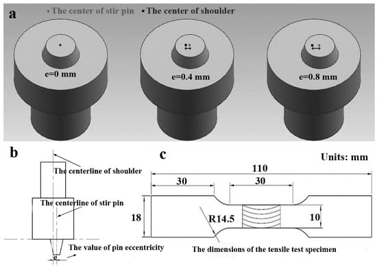
Figure 1.
The (a) 3D and (b) 2D diagrammatic drawing of pin eccentricity; (c) the dimensions of the tensile test specimen.
Table 2.
Experimental welding parameters’ combination in the present work.
The microstructure in the NZ was observed using the optical microscopy (OM, Olympus DSX-500, Olympus, Tokyo, Japan), electron back-scattered diffraction (EBSD, FEI Quanta 600, FEI, Portland, OR, USA), and transmission electron microscopy (TEM, Tecnai G220, FEI, Portland, OR, USA). Samples for OM were prepared by grinding, mechanical polishing, and then etching with the Keller’s reagent. Electro-polishing with a solution of 10% perchloric acid and 90% ethanol was used for obtaining qualified EBSD samples. In addition, in the EBSD mapping, the low-angle grain boundaries (LAGBs, 2° < θ < 15°) and high-angle grain boundaries (HAGBs, θ > 15°) were marked as white and black lines, respectively. The foils for TEM were prepared by twinjet electro-polishing with a solution of 30% nitric acid in methanol at −30°. A differential scanning calorimeter (DSC, Setaram DSC-131, Setaram, Lyons, France) was also applied to quantify the amount of strengthening precipitates; the DSC samples were 4.5 mm in diameter and were heated at a constant heating rate of 10 K/min from 25 to 550 °C.
Both Vickers hardness and tensile tests were employed to characterize the mechanical properties of FSW joints. In order to minimize the influence of natural aging on the mechanical properties of joints, the time between completion of the welding and mechanical testing was controlled within two days. Hardness tests were conducted across the joints using 50 g load and 5 s dwell time, with the interval of 0.5 mm between the neighboring measured points. Tensile tests were carried out at ambient temperature with a strain rate of 1 × 10⁻³ s−1. Specimens for tensile tests were cut perpendicular to the welding direction, and the detailed dimensions of the tensile specimens are indicated in Figure 1c. After tensile tests, the fracture surfaces were investigated by OM and scanning electron microscopy (SEM, FEI Quanta 600, FEI, Portland, OR, USA).
3. Results and Discussion
3.1. The Microstructure of the Base Metal
The morphologies of the grains in the base metal are shown in Figure 2a,b. The grains in AA5052 were elongated due to rolling, while some coarse equiaxed grains were observed in AA6061. As shown in Figure 2c, the density of dislocations in AA5052 was high, and a few second-phase particles (i.e., Fe–Mn phase) could be found in the matrix on account of its relatively low alloy element content [13]. Differently, large amounts of fine strengthening precipitates were embedded uniformly throughout the matrix of AA6061 (Figure 2d). Furthermore, neither extra reflection nor diffuse scattering were detected in the selected area diffraction pattern (SADP). Based on our previous study [19], these fine strengthening precipitates were mainly Guinier–Preston (GP) zones, and these precipitates preferred to form during natural aging. The mechanical properties of AA5052 and AA6061 are listed in Table 3, and compared with AA5052, the hardness and tensile strength of AA6061 were much higher.
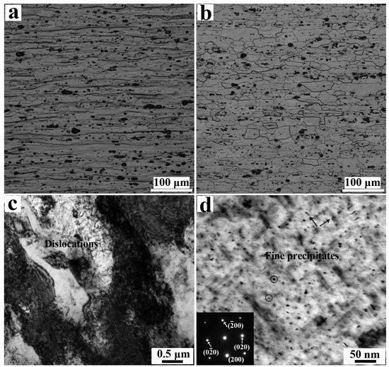
Figure 2.
The morphologies of grains in the base metal of (a) AA5052 and (b) AA6061, (c) high density of dislocations in AA5052, and (d) abundant fine precipitates in AA6061.
Table 3.
Hardness and tensile properties of AA5052 and AA6061.
3.2. The Choice of Optimal Alloys Relative Placement during FSW
It has been reported that the alloys’ relative placement affects the quality of the FSW process [20,21], while there is still no agreement on the optimal alloys’ relative placement. Therefore, optimizing the alloys’ relative placement for dissimilar aluminum FSW is necessary. Figure 3 shows the cross-section of FSW joints produced by different alloys’ relative placements, and it can be seen that placing soft AA5052 in the advancing side led to the formation of internal defects (cavities); besides, the mixture of alloys was absent and a zigzag line was detected in the NZ (Figure 3a). By contrast, the internal defects were avoided by inverting the alloys’ relative placement, i.e., placing hard AA6061 in the advancing side (Figure 3b). Furthermore, the mixture of alloys became distinct and the “onion ring” formed in the pin-affected zone. The grains in the NZ were refined due to the dynamic recrystallization (DRX) during the FSW [22], and the difference in the average grain size between joint P0 and joint P0(R) was not significant.
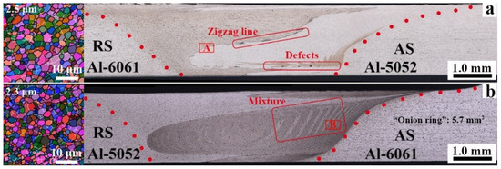
Figure 3.
The cross-section of the friction stir welding (FSW) joints produced by (a) placing soft AA5052 in the advancing side, joint P0(R), and (b) placing hard AA6061 in the advancing side, joint P0.
In addition, the element distribution in the NZ is analyzed as shown in Figure 4. The difference in Si and Mg contents at the interface of AA5052/AA6061 in joint P0(R) was distinct (Figure 4a,b), which indicates that the atomic diffusion during FSW was inhibited owing to the relatively low solid-state welding temperature [1]. By contrast, the mixing of alloys in joint P0 became sufficient, and distinct “onion rings” could be found in the NZ. However, the atomic diffusion was still deficient, justifying that the mixture of alloys was mainly mechanical (Figure 4c,d). Combined with the results of the optical and element analysis, it can be concluded that the dark lines in the “onion rings” were AA5052, while AA6061 were the light ones.
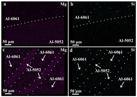
Figure 4.
Energy dispersive spectroscopy (EDS) maps showing the Mg and Si contents in (a), (b) region A of joint P0(R) and (c), (d) region B in joint P0.
During FSW, the materials ahead of the stir tool are sheared into the retreating side (RS), and then pushed back to the advancing side (AS) under the stir action of the tool. Thus, the materials flow in the NZ can be divided into two parts: part (i) pushing process and part (ii) filling and mixing process (Figure 5). In part (i), the materials in front of the stir tool are sheared and pushed in the RS, and subsequently, in part (ii), the materials rotate around the stir pin, fill the cavity and mix with the materials in the AS. Li et al. [23] found that the shear force at the front of the stir tool was much stronger than that at the back of the tool, thus the material flow became difficult in part (ii) due to the decrease in the shear force. When placing the hard AA6061 in the RS, the shear force provided in part (ii) is not strong enough for maintaining the material flow, leading to the formation of cavities. Furthermore, on account of the insufficient material flow, the oxide layer remains, and the continuous zigzag line appears in the NZ [24]. In order to avoid the internal defects, AA6061 should be sufficiently softened before part (ii). It has been reported that the welding temperature of AS is higher than that of RS [25], therefore, inverting the alloys’ relative placement is beneficial for heating and softening AA6061. As a result, the material flow becomes sufficient, avoiding the cavities and facilitating the mixing of materials. Besides, sufficient material flow contributes to the formation of the “onion ring” [26], hence, obvious characterization of “onion rings” is detected by placing AA6061 in the AS.
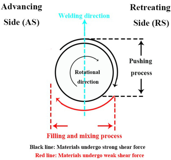
Figure 5.
Schematic diagram of material flow during the FSW process.
3.3. The Macro and Microstructure of Nugget Zone Produced by Pin-Eccentric FSW
Figure 6 shows the cross-section of FSW joints produced by different pin-eccentric stir tools, and all the NZs were free of internal defects. Moreover, the area of the “onion ring” enlarged as the pin eccentricity increased, which is also consistent with the results of Reference [13]. The application of pin eccentricity strengthens the stir-behavior of the pin, promoting the material flow and enlarging the area of the “onion ring”.
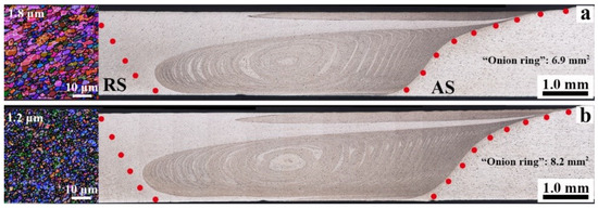
Figure 6.
The cross-section of the FSW joints produced by (a) the 0.4 mm pin-eccentric stir tool, joint P0.4, and (b) the 0.8 mm pin-eccentric stir tool, joint P0.8.
Compared with the grains in the NZ of joint P0 (Figure 3b), the application of pin eccentricity further refined the grains, from 2.3 μm for joint P0 to 1.2 μm for joint P0.8 (Figure 6b). It has been reported that the grain size in the NZ is controlled by the welding peak temperature [27], where the low welding peak temperature contributes to the grain refinement. Essa et al. [28] stated that the welding peak temperature becomes lower as the pin eccentricity increases due to the elevated cooling rate caused by the pin eccentricity, and thus, joint P0.8 showed the finest grains and the average grain size was only half that of joint P0. Differently, for similar friction stir processed AA5052 [13], the grain size produced by the 0.8 mm pin-eccentric stir tool was a bit coarser than that of the 0.4 mm pin-eccentric stir tool, and we illustrated that the materials of the 0.8 mm pin eccentricity became fluid-like, weakened stir-behavior and the cooling rate, leading to the growth of grain. In the present work, the NZ consisted of two alloys, in comparison to AA5052, the thermal conductivity of AA6061 was much higher [29], and thus the cooling rate of dissimilar aluminum NZ was improved. As a result, the stir-behavior of the 0.8 mm pin-eccentric stir tool was maintained and the grains of joint P0.8 were refined further.
The welding heat input in the present work was relatively low, which was not high enough for completing DRX, and hence, dislocations and sub-grain boundaries can be found in the NZ as shown in Figure 7a–c. The recrystallization map of joints produced by different pin-eccentric stir tools is indicated in Figure 7d–f, and the deformed grain (Def) are colored in red, while the sub-structured (Sub) and recrystallized grain (Rec) are in yellow and blue, respectively [19,30]. It can be concluded that the fraction of Rec decreased as the pin eccentricity increased, which decreased from 82% for joint P0 to 64% for joint P0.8. During the DRX process, dislocations aligned to form deformed and sub-structured grains, and then these structures grew into recrystallized grains with high-angle boundaries by consuming the dislocations [31]. The application of pin eccentricity elevated the cooling rate, shortening the period for DRX, and thus, large amounts of dislocations and sub-grain boundaries remained in the NZ.
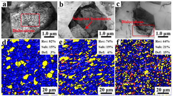
Figure 7.
TEM micrographs in the nugget zone (NZ) of joint (a) P0, (b) P0.4, (c) P0.8 and the corresponding recrystallization map of joint (d) P0, (e) P0.4, (f) P0.8.
The distribution of second-phase particles and strengthening precipitates in the NZ was also observed by TEM, as shown in Figure 8. The difference in the morphology of stable Fe–Mn phase particles was negative between the non-pin-eccentric and pin-eccentric FSW joints, and the number of these particles was relatively low (Figure 8a–c). The average size of Fe–Mn phase particles was less than 100 nm, thus, the stir-behavior of the pin could not break these particles further [13], weakening the impact of pin eccentricity on the morphology of the second-phase particles. Besides, numerous coarsened strengthening precipitates were observed in the NZ (Figure 8d–f), which are defined as β′ (β′′) phase [19]. During the FSW process, both the dissolution and coarsening of precipitates proceed, which is controlled by the welding heat input and initial morphology of precipitates [19,27,32]. The welding heat input used in the present study was relatively low, and the initial precipitates prefer to coarsening rather than dissolution [19]. Therefore, large amounts of coarsened precipitates were observed in the NZ.
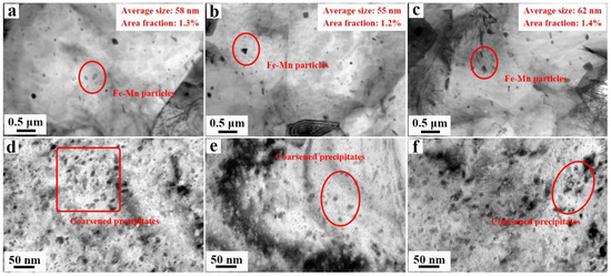
Figure 8.
The distribution of second-phase particles in the NZ of joint (a) P0, (b) P0.4, (c) P0.8 and the observation of strengthening precipitates in the NZ of joint (d) P0, (e) P0.4, (f) P0.8.
The DSC was also applied to analyze the evolution of strengthening precipitates. Neither an exothermic nor endothermic peak were detected in the DSC curves (as shown in Figure 9), indicating that all the initial fine GP zones transformed to the coarse β′ (β′′) phase [19]. It has been reported that the cooling rate elevates with increasing pin eccentricity [33]; however, the application of pin eccentricity hardly affected the evolution of strengthening precipitates in the present work. Based on our previous studies [34], coarsening proceeds rapidly if there is an existing population of precipitates available for growth: the amount of initial GP zones in the matrix is high, and thus, the coarsening proceeds completely in a relatively short period, weakening the impact of the cooling rate, and therefore, the distribution and morphology of strengthening precipitates in all joints are similar.
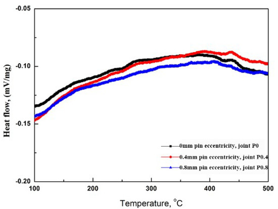
Figure 9.
Differential Scanning Calorimetric (DSC) curves of the precipitates in the NZ produced by different pin-eccentric stir tools.
3.4. The Mechanical Properties of Pin-Eccentric FSW Joints
Figure 10 shows the hardness results of FSW joints produced by different pin-eccentric stir tools, and the hardness distribution profile was asymmetric due to the different mechanical properties between AA5052 and AA6061. Furthermore, the hardness of all NZs decreased after FSW compared with base metals (Figure 10a). Both the DRX and coarsening of strengthening precipitates happened during FSW, the occurrence of DRX eliminates the work hardening [35] and the coarsening of precipitates gives rise to over-aging [36], leading to the softening of NZ.
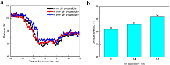
Figure 10.
(a) Hardness distribution across the cross-section of FSW joints and (b) the average hardness of NZ produced by different pin-eccentric stir tools.
The average hardness of the NZ elevated as the pin eccentricity increased, which elevated from 61 HV for joint P0 to 66 HV for joint P0.8 (Figure 10b). As mentioned in Section 3.3, the grains in the NZ became finer and the fraction of deformed/sub-structured grain became higher as the pin eccentricity increased, which led to the improvement of both the grain-boundary and dislocation strengthening [19], elevating the hardness of the NZ.
The results of tensile tests are listed in Table 4, and it can be seen that all joints failed in the NZ due to the relatively low hardness of the NZ. In addition, the tensile strength elevated with the increasing pin eccentricity, and in comparison to joint P0, an 8% increment in yield/ultimate tensile strength was obtained using the 0.8 mm pin-eccentric stir tool.
Table 4.
Tensile properties of FSW joints produced by different pin-eccentric stir tools.
It was also interesting to find that the total elongation of joints was improved by utilizing the pin-eccentric stir tool, and then, the fracture surface of the FSW joints was observed for analysis (as shown in Figure 11). As for joint P0, the fracture surface was relatively flat and a few dimples were detected, which indicates that the initial microstructure in the NZ was inhomogeneous. The inhomogeneous microstructure led to the mixed fracture and reduced the plasticity of the joints. By contrast, the fracture surfaces of joints P0.4 and P0.8 were characterized by fine and round equiaxed dimples, which indicated that the application of pin eccentricity homogenized the microstructures in the NZ and the mode of failure changes into ductile fractures [34], increasing the plasticity of pin-eccentric FSW joints.
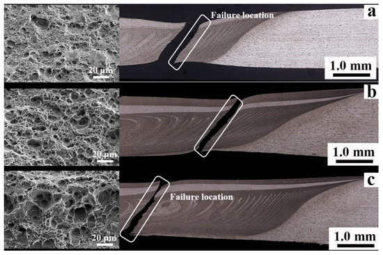
Figure 11.
The fracture surface of the tensile specimens produced by the stir tools (a) without and with (b) 0.4 mm and (c) 0.8 mm pin eccentricity.
4. Conclusions
The effect of pin eccentricity on dissimilar FSW behavior of aluminum alloys AA5052 and AA6061 was researched, and the following conclusions were obtained:
1. For dissimilar welded AA5052 and AA6061, placing soft AA5052 in the advancing side led to the formation of internal defects and a zigzag line in the NZ, while sound FSW joints could be obtained by inverting the alloys’ relative placement.
2. The employment of pin eccentricity enhanced the material flow and enlarged the area of the “onion ring”. Both the average grain size and the fraction of recrystallized grain in the NZ decreased as the pin eccentricity increased.
3. In comparison to the base metal, all NZs were softened due to the occurrence of DRX and over-aging. Both the hardness and tensile properties of FSW joints can be improved by employing the pin-eccentric stir tool, and more than 5% increment in tensile strength can be obtained when the pin eccentricity is applied.
Author Contributions
Conceptualization, Y.C.; methodology, Y.C., H.W., and H.L.; software, Y.C., H.L., H.D., and F.Z.; formal analysis, Y.C.; investigation, Y.C., H.W., H.L., and X.W.; resources, Y.C. and H.W.; data curation, Y.C., H.W., and H.L.; writing—original draft preparation, Y.C.; writing—review and editing, H.L., H.D., X.W., and J.Z.; project administration, Y.C.; funding acquisition, Y.C.
Funding
This research was funded by the Nature Science Foundation of Liaoning Province, No. 20180550058 and the Fundamental Research Funds for the Central Universities of China, No. N180303029.
Conflicts of Interest
The authors declare no conflict of interest.
References
- Chen, Y.; Ding, H.; Cai, Z.H.; Zhao, J.W.; Li, J.Z. Microstructural and mechanical characterization of a dissimilar friction stir-welded AA5083-AA7B04 butt joint. J. Mater. Eng. Perform. 2017, 26, 530–539. [Google Scholar] [CrossRef]
- Wang, B.; Lei, B.B.; Zhu, J.X.; Feng, Q.; Wang, L.; Wu, D. EBSD study on microstructure and texture of friction stir welded AA5052-O and AA6061-T6 dissimilar joint. Mater. Des. 2015, 87, 593–599. [Google Scholar] [CrossRef]
- Yan, Y.; Zhang, D.T.; Qiu, C.; Zhang, W. Dissimilar friction stir welding between 5052 aluminum alloy and AZ31 magnesium alloy. Trans. Nonferrous Met. Soc. China 2010, 20, s619–s623. [Google Scholar] [CrossRef]
- Mishra, R.S.; Ma, Z.Y. Friction stir welding and processing. Mater. Sci. Eng. R 2005, 50, 1–78. [Google Scholar] [CrossRef]
- Liu, P.L.; Li, W.Y.; Li, N.; Xu, Y.X.; Chen, D.L. Exfoliation corrosion of friction stir welded dissimilar 2024-to-7075 aluminum alloys. Mater. Charact. 2019, 147, 93–100. [Google Scholar]
- Hamed, J.A. Influences of pin profile on the mechanical and microstructural behaviors in dissimilar friction stir welded AA6082-AA7075 butt joint. Mater. Des. 2015, 67, 413–421. [Google Scholar]
- Palanivel, R.; Mathews, P.K.; Murugan, N.; Dianharan, I. Effect of tool rotational speed and pin profile on the microstructure and tensile strength of dissimilar friction stir welded AA5083-H111 and AA6351-T6 aluminum alloy. Mater. Des. 2012, 40, 7–16. [Google Scholar] [CrossRef]
- Ahmed, M.M.Z.; Ataya, S.; Seleman, M.M.E.; Ammar, H.R.; Ahmed, E. Friction stir welding of similar and dissimilar AA7075 and AA5083. J. Mater. Process. Technol. 2017, 242, 77–91. [Google Scholar] [CrossRef]
- Rodriguez, R.I.; Jordon, J.B.; Allison, P.G.; Rushing, T.; Garcia, L. Microstructure and mechanical properties of dissimilar friction stir welding of 6061-to-7075 aluminum alloys. Mater. Des. 2015, 83, 60–65. [Google Scholar] [CrossRef]
- Saju, T.P.; Narayanan, R.G. Effect of tool plunge depth on joint formation and mechanical performance of friction stir forming joints made between AA5052-H32 and AA6061-T6 sheet metals. Trans. Nonferrous Met. Soc. China 2018, 28, 603–628. [Google Scholar] [CrossRef]
- Elangovan, K.; Balasubramanian, V. Influences of tool pin profile and welding speed on the formation of friction stir processing zone in AA2219 aluminum alloy. J. Mater. Process. Technol. 2008, 200, 163–175. [Google Scholar] [CrossRef]
- Elangovan, K.; Balasubrananian, V. Influences of tool pin profile and tool shoulder diameter on the formation of friction stir processing zone in AA6061 aluminum alloy. Mater. Des. 2008, 29, 362–373. [Google Scholar] [CrossRef]
- Chen, Y.; Wang, H.; Wang, X.Y.; Ding, H.; Zhao, J.W.; Zhang, F.H.; Ren, Z.H. Influence of tool pin eccentricity on microstructural evolution and mechanical properties of friction stir processed Al-5052 alloy. Mater. Sci. Eng. A 2019, 739, 272–276. [Google Scholar] [CrossRef]
- Mao, Y.Q.; Ke, L.M.; Liu, F.C.; Liu, Q.; Huang, C.P.; Xing, L. Effect of tool pin eccentricity on microstructure and mechanical properties in friction stir welded 7075 aluminum alloy thick plate. Mater. Des. 2014, 62, 324–343. [Google Scholar] [CrossRef]
- Silva, A.A.M.D.; Arruti, E.; Janeiro, G.; Aldanondo, E.; Alvarez, P.; Echeverria, A. Materials flow and mechanical behavior of dissimilar AA2024-T3 and AA7075-T6 aluminum alloys friction stir welds. Mater. Des. 2011, 32, 2021–2027. [Google Scholar] [CrossRef]
- Aval, H.J.; Serajzadeh, S.; Kokabi, A.H. Evolution of microstructures and mechanical properties in similar and dissimilar friction stir welding of AA5086 and AA6061. Mater. Sci. Eng. A 2011, 528, 8071–8083. [Google Scholar] [CrossRef]
- Howeyze, M.; Arabi, H.; Eivana, A.R.; Jafarian, H.R. Strengthening of AA5052 aluminum alloy by equal channel angular pressing followed by softening at room temperature. Mater. Sci. Eng. A 2018, 720, 160–168. [Google Scholar] [CrossRef]
- Malopheyev, S.; Vysotskiy, I.; Kulitskiy, V.; Mironov, S.; Kaibyshev, R. Optimization of processing-microstructure-properties relationship in friction-stir welded 6061-T6 aluminum alloy. Mater. Sci. Eng. A 2016, 662, 136–143. [Google Scholar] [CrossRef]
- Chen, Y.; Jiang, Y.F.; Zhang, F.H.; Ding, H.; Zhao, J.W.; Ren, Z.H. Water cooling effects on the microstructural evolution and mechanical properties of friction-stir-processed Al-6061 alloy. Trans. Indian Inst. Met. 2018, 71, 3077–3087. [Google Scholar] [CrossRef]
- Dilio, J.J.S.; Koilraj, M.; Sundareswaran, V.; Ram, G.D.J.; Rao, S.R.K. Microstructural characterization of dissimilar friction stir welds between AA2219 and AA5083. Trans. Indian Inst. Met. 2010, 63, 757–764. [Google Scholar]
- Cavaliere, P.; Santis, A.D.; Panella, F.; Souillace, A. Effect of welding parameters on mechanical and microstructural properties of dissimilar AA6082-AA2024 joints produced by friction stir welding. Mater. Des. 2009, 30, 609–616. [Google Scholar] [CrossRef]
- Chen, Y.; Ding, H.; Li, J.Z.; Cai, Z.H.; Zhao, J.W.; Yang, W.J. Influence of multi-pass friction stir processing on the microstructure and mechanical properties of Al-5083 alloy. Mater. Sci. Eng. A 2016, 650, 281–289. [Google Scholar] [CrossRef]
- Li, W.Y.; Li, J.F.; Zhang, Z.H.; Gao, D.L.; Chao, Y.J. Metal flow during friction stir welding of 7075-T651 aluminum alloy. Exp. Mech. 2013, 53, 1573–1582. [Google Scholar] [CrossRef]
- Malopheyev, S.; Mironov, S.; Kuliskiy, V.; Kaibyshev, R. Friction-stir welding of ultra-fine grained sheets of Al-Mg-Sc-Zr alloy. Mater. Sci. Eng. A 2015, 627, 123–139. [Google Scholar] [CrossRef]
- Sharghi, E.; Farzadi, A. Simulation of strain rate, materials flow, and nugget shape during dissimilar friction stir welding of AA6061 aluminum alloy and Al-Mg2Si composite. J. Alloys Compd. 2018, 748, 953–960. [Google Scholar] [CrossRef]
- Liu, X.C.; Wu, C.S. Material flow in ultrasonic vibration enhanced friction stir welding. J. Mater. Process. Technol. 2015, 225, 32–44. [Google Scholar] [CrossRef]
- Chen, Y.; Ding, H.; Li, J.Z.; Zhao, J.W.; Fu, M.J.; Li, X.H. Effect of welding heat input and post-welded heat treatment on hardness of stir zone for friction stir-welded 2024-T3 aluminum alloy. Trans. Nonferrous Met. Soc. China 2015, 25, 2524–2532. [Google Scholar] [CrossRef]
- Essa, A.R.S.; Ahmed, M.M.Z.; Mohamed, A.K.Y.A.; Ei-Nikhaily, A.E. Analytical model of heat generation for eccentric cylindrical pin in friction stir welding. J. Mater. Res. Technol. 2016, 5, 234–240. [Google Scholar] [CrossRef]
- Woodcraft, A.L. Predicting the thermal conductivity of aluminum alloys in the cryogenic to room temperature. Cryogenics 2005, 45, 421–431. [Google Scholar] [CrossRef]
- Chen, H.Y.; Fu, L.; Liang, P. Microstructure, texture and mechanical properties of friction stir welded butt joints of 2A97 Al-Li alloy ultra-thin sheets. J. Alloys Compd. 2017, 692, 155–169. [Google Scholar] [CrossRef]
- Su, J.Q.; Nelson, T.W.; Sterling, J. Microstructure evolution during FSW/FSP of high strength aluminum alloys. Mater. Sci. Eng. A 2005, 405, 277–286. [Google Scholar] [CrossRef]
- Chen, Y.; Ding, H.; Cai, Z.H.; Zhao, J.W.; Li, J.Z. Effect of initial base metal temper on microstructure and mechanical properties of friction stir processed Al-7B04 alloy. Mater. Sci. Eng. A 2016, 650, 396–403. [Google Scholar] [CrossRef]
- Chen, Y.; Jiang, Y.F.; Ding, H.; Zhao, J.W.; Li, J.Z. Effects of friction-stir processing with water cooling on the properties of an Al-Zn-Mg-Cu alloy. Mater. Sci. Technol. 2018, 34, 153–160. [Google Scholar] [CrossRef]
- Malopheyev, S.; Kulitskiy, V.; Mironov, S.; Zhemchuzhnikova, D.; Kaibyshev, R. Friction-stir welding of an Al-Mg-Sc-Zr alloy in as-fabricated and work-hardened condtions. Mater. Sci. Eng. A 2014, 600, 159–170. [Google Scholar] [CrossRef]
- Chen, Y.; Ding, H.; Malopheyev, S.; Kaibyshev, R.; Cai, Z.H.; Yang, W.J. Influence of multi-pass friction stir processing on microstructure and mechanical properties of 7B04-O Al alloy. Trans. Nonferrous Met. Soc. China 2017, 27, 789–796. [Google Scholar] [CrossRef]
- Hao, H.L.; Ni, D.R.; Huang, N.; Wang, D.; Xiao, B.L.; Nie, Z.R.; Ma, Z.Y. Effect of welding parameters on microstructure and mechanical properties of friction stir welded Al-Mg-Er alloy. Mater. Sci. Eng. A 2013, 559, 889–896. [Google Scholar] [CrossRef]
© 2019 by the authors. Licensee MDPI, Basel, Switzerland. This article is an open access article distributed under the terms and conditions of the Creative Commons Attribution (CC BY) license (http://creativecommons.org/licenses/by/4.0/).