Fatigue Life Improvement of the High Strength Steel Welded Joints by Ultrasonic Impact Peening

 ,
, 
Abstract
:1. Introduction
2. Experiment Preparation
2.1. Experimental Material and Weld Execution
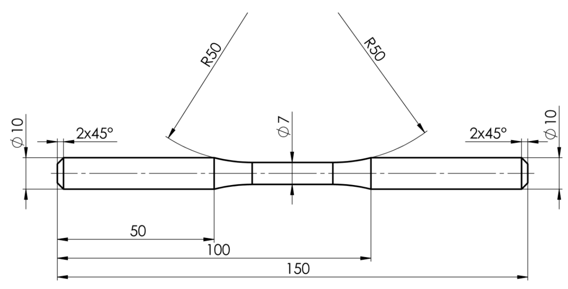
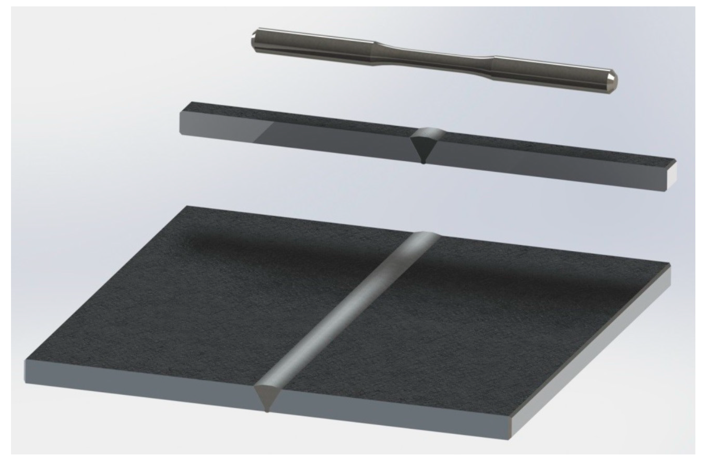
2.2. Specimens Manufacturing and Surface Strengthening
3. Results and Discussion
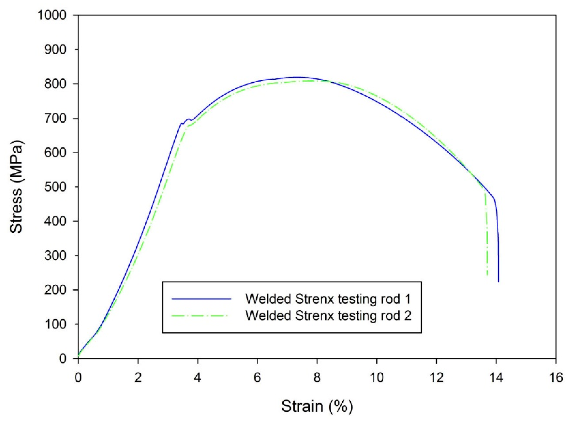
3.1. Basic Mechanical Properties
3.2. Residual Stress Analysis
3.3. Fatigue Life Results
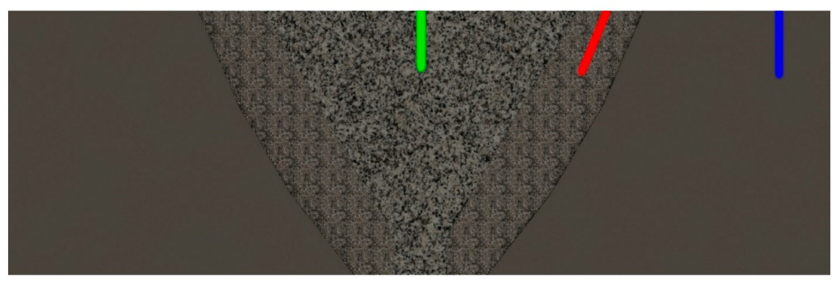
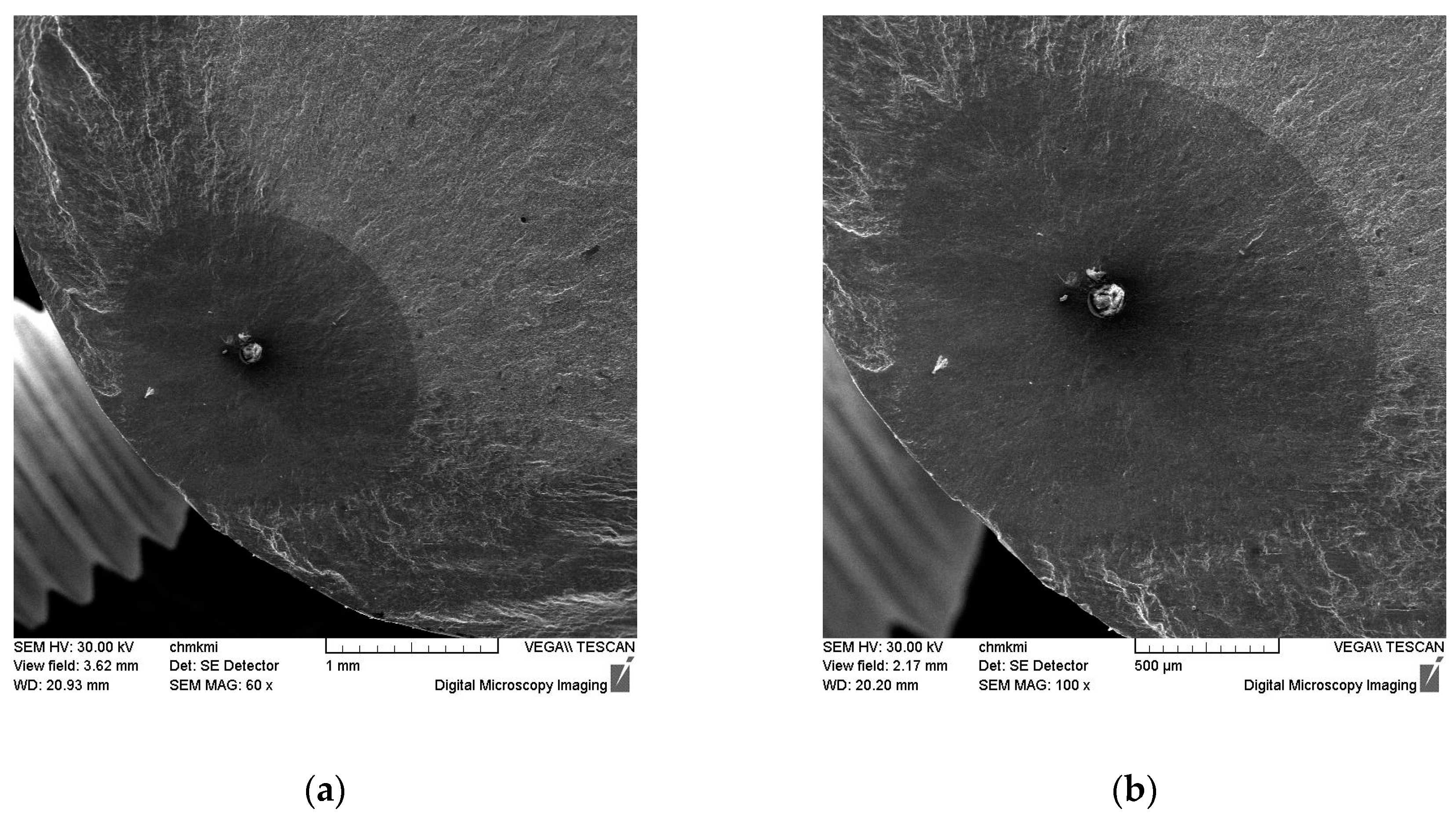
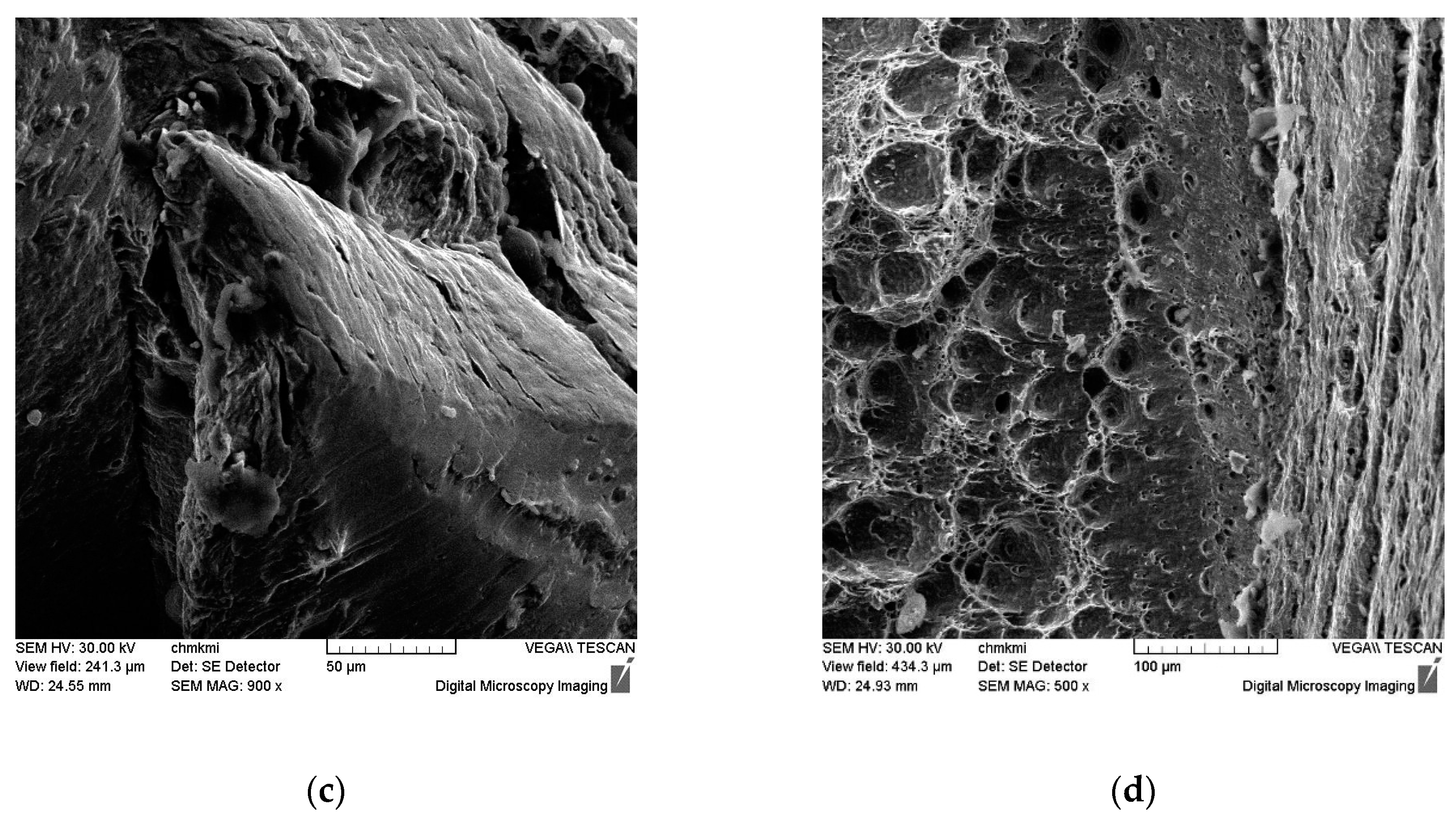
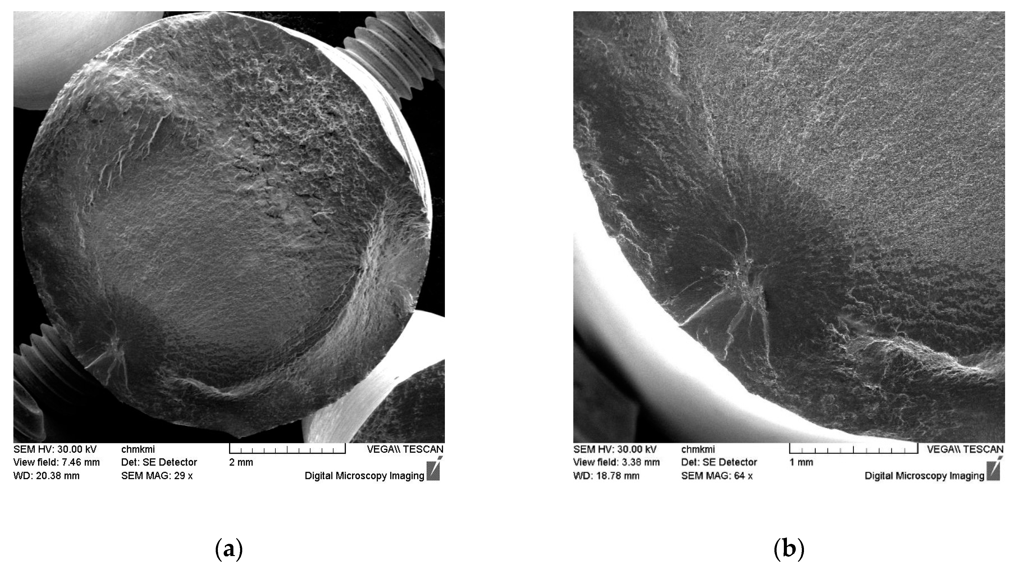
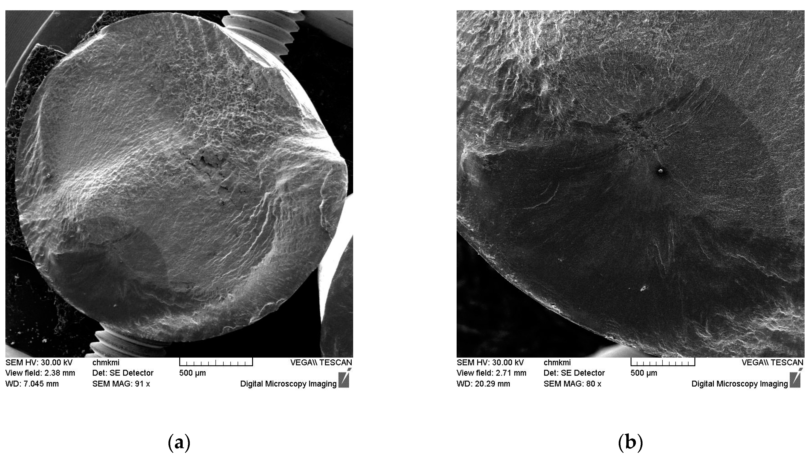
4. Fracture Surface Analysis
5. Conclusions
- -
- Joining of Strenx 700 MC steel with OK Aristorod 69 welding wire created a joint with similar ultimate tensile strength, however the yield point decreased for approx. 50 MPa.
- -
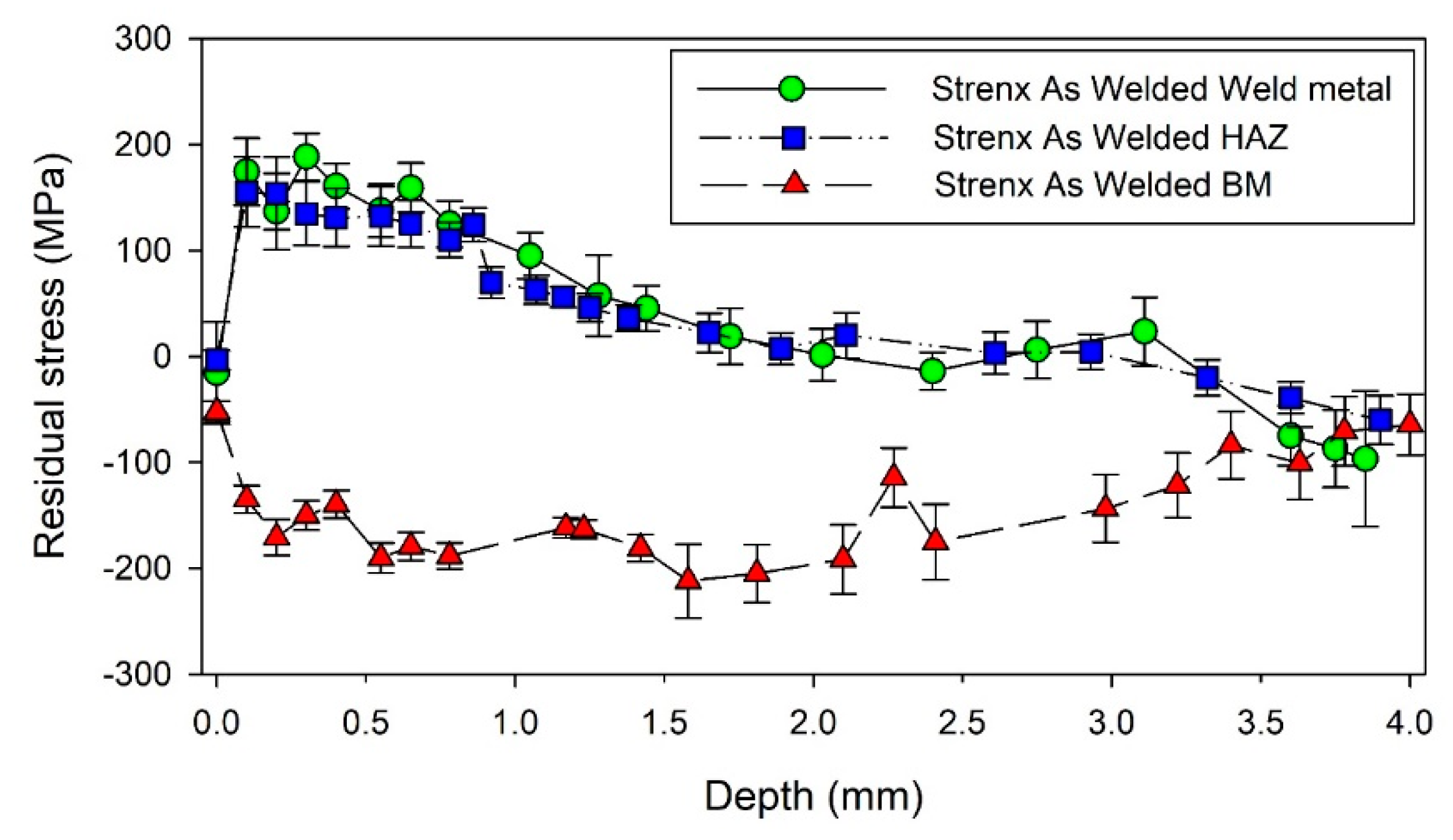
- The welding process caused accumulation of tensile residual stresses in the weld metal and heat affected zone, which reached maximal value of approximately 200 MPa.
- -
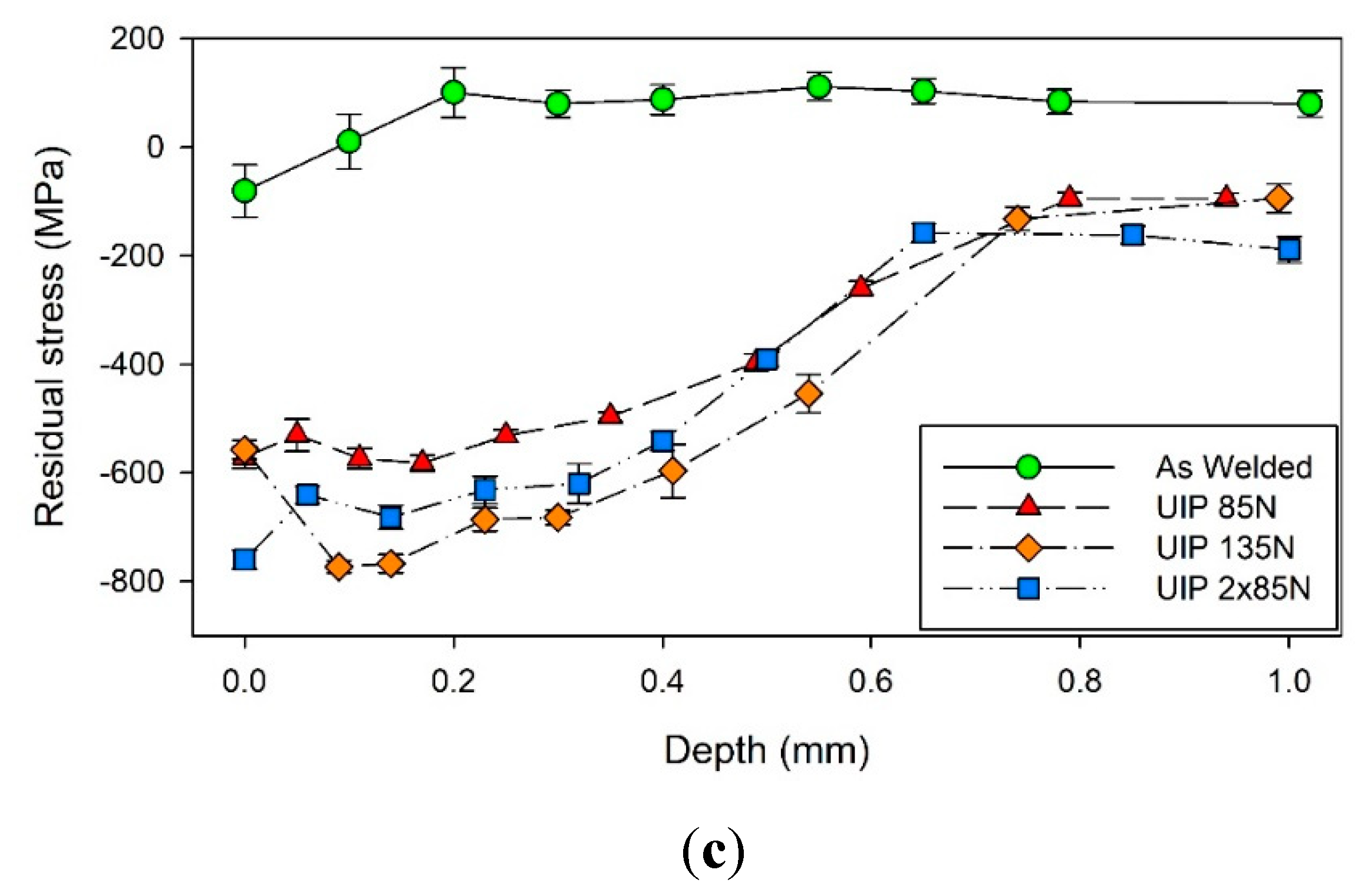
- The ultrasonic impact peening (UIP) was able to transform the tensile residual stresses in the weld metal and heat affected zone into compressive ones, with maximal values between −400 and −800 MPa.
- -
- Increasing of severity of the ultrasonic impact peening increased the values of residual stresses correspondingly.
- -
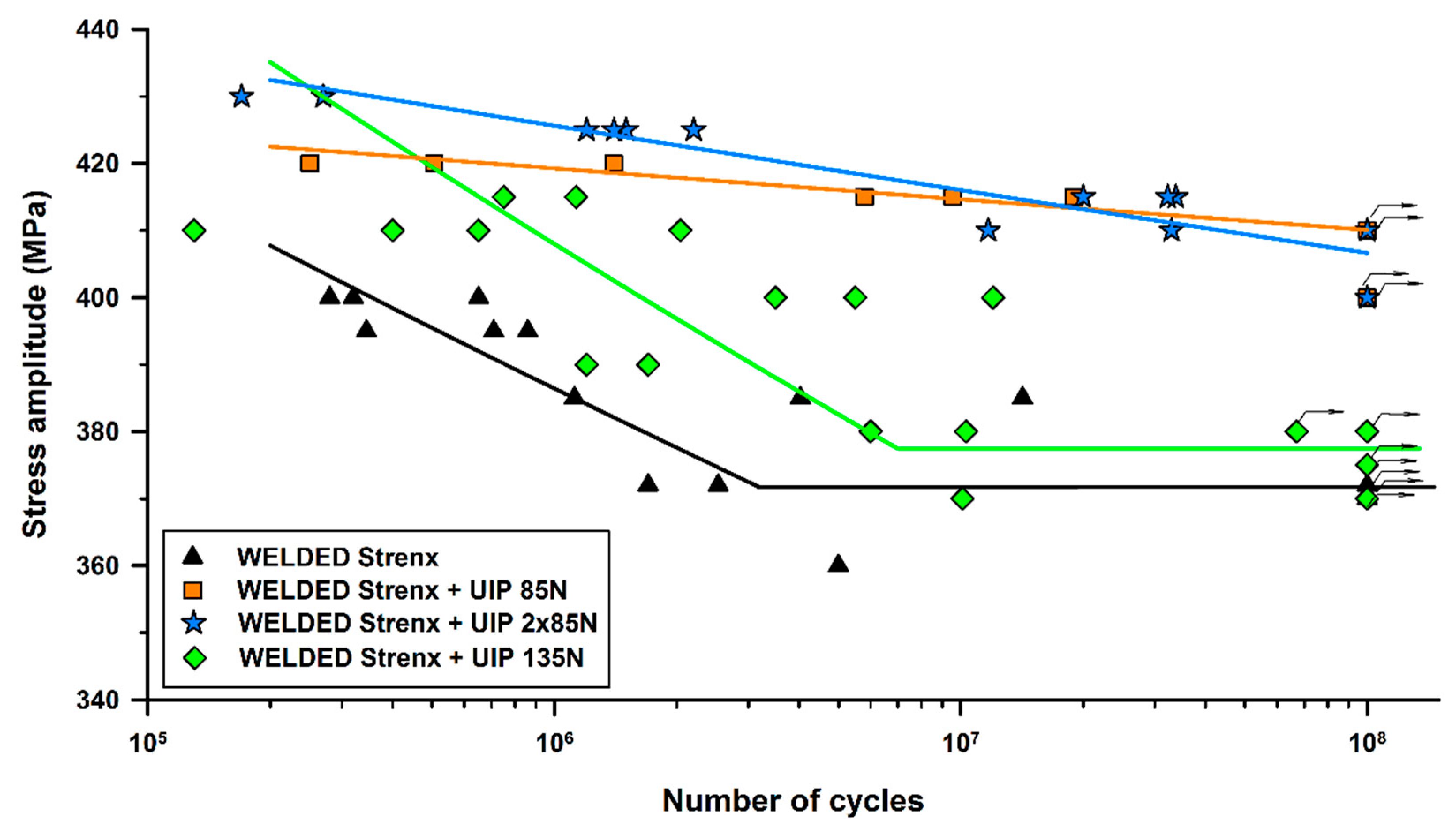
- The highest fatigue life improvement was reached by the double peening with the 85 N contact force, where the fatigue limit for N = 108 cycles increased from 370 MPa to 410 MPa, while the S–N curve in the region of the lower number of cycles to failure was approx. 10 MPa above the single treatment with 85 N contact force.
- -
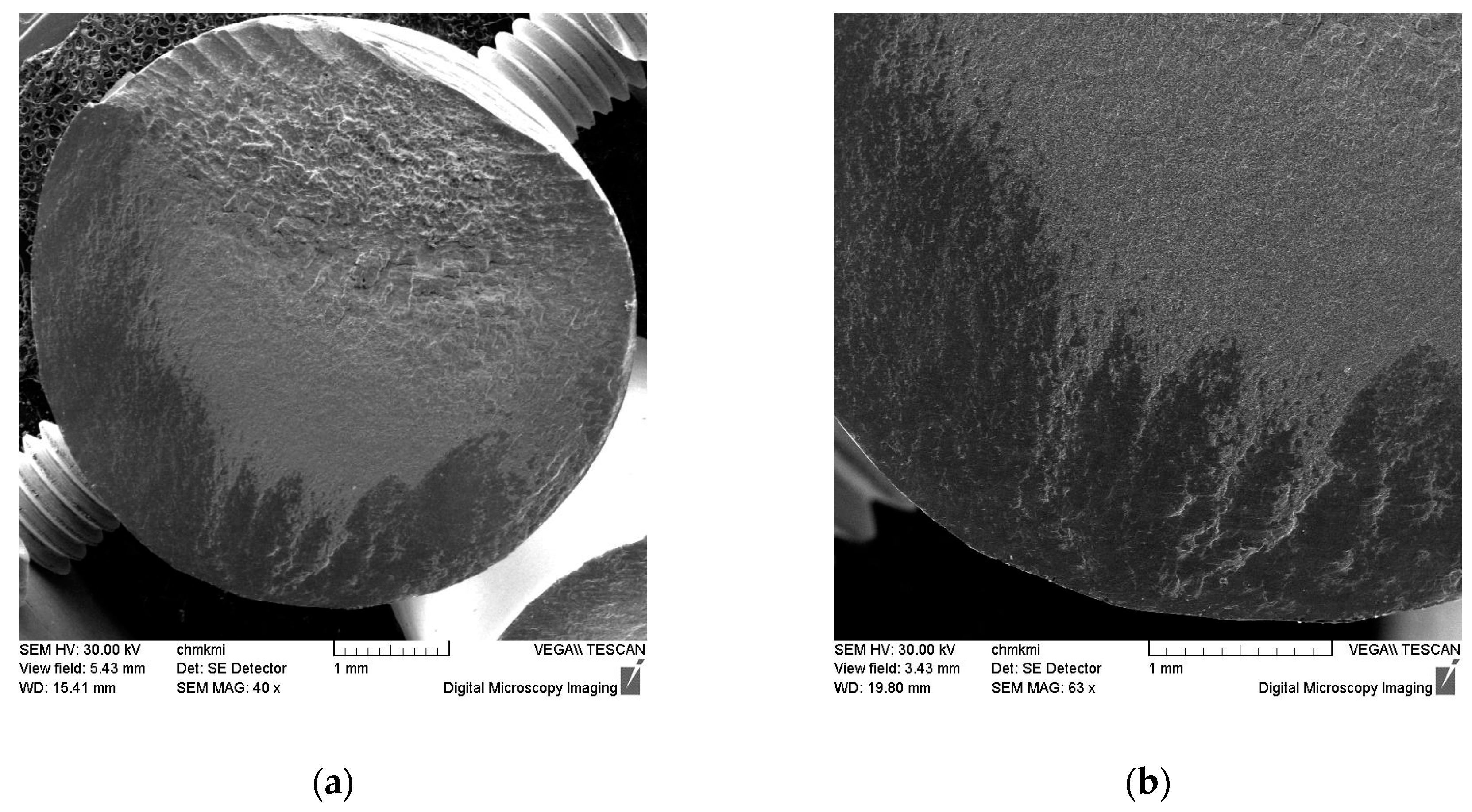
- Since the fatigue crack always initiated in the HAZ, this area can be considered as the weakest point of the welded joint in terms of cyclic loading.
- -
- Treatment with the UIP process caused shifting of the fatigue crack initiation point from the surface to the sub-surface volume of material, where weld defects acted as the most significant stress concentrators.
Author Contributions
Funding
Conflicts of Interest
References
- Shao, Y.; Liu, C.; Yan, Z.; Li, H.; Liu, Y. Formation mechanism and control methods of acicular ferrite in HSLA steels: A review. J. Mater. Sci. Technol. 2018, 34, 737–744. [Google Scholar] [CrossRef]
- Park, D.B.; Huh, M.Y.; Shim, J.H.; Suh, J.Y.; Lee, K.H.; Jung, W.S. Strengthening mechanism of hot rolled Ti and Nb microalloyed HSLA steels containing Mo and W with various coiling temperature. J. Mater. Sci. Eng. A 2013, 560, 528–534. [Google Scholar] [CrossRef]
- Bakkaloğlu, A. Effect of processing parameters on the microstructure and properties of an Nb microalloyed steel. Mater. Lett. 2002, 56, 263–272. [Google Scholar] [CrossRef]
- Charleux, M.; Poole, W.J.; Militzer, M.; Deschamps, A. Precipitation behavior and its effect on strengthening of an HSLA-Nb/Ti steel. Metall. Mater. Trans. A 2001, 32, 1635–1647. [Google Scholar] [CrossRef]
- Jesus Jorge, J.; Cândido, V.S.; Rios da Silva, A.C.; Costa Garcia Filho, F.; Camposo Pereira, A.; Santos da Luz, F.; Neves Monteiro, S. Mechanical properties and microstructure of SMAW welded and thermically treated HSLA-80 steel. J. Mater. Res. Technol. 2018, 7, 598–605. [Google Scholar] [CrossRef]
- Lu, J.; Lu, K. Surface nanocrystallization (SNC) of materials and its effect on mechanical behavior. Comp. Struct. Int. 2003, 8, 495–528. [Google Scholar]
- Lu, K.; Lu, J. Surface nanocrystallizaion (SNC) of metallic materials—presentation of the concept behind a new approach. J. Mater. Sci. Technol. 1999, 15, 193–197. [Google Scholar]
- Abadie, F.X.; Beckmerhagen, P.; Belassel, M. Shot peening: A Dynamic Application and its Future, 3rd ed.; Metal Finishing News: Wetzikon, Switzerland, 2009; pp. 17–44. [Google Scholar]
- Bagheri, S.; Guagliano, M. Review of shot peening processes to obtain nanocrystalline surfaces in metal alloys. Surf. Eng. 2009, 25, 3–14. [Google Scholar] [CrossRef]
- Bagherifard, S.; Guagliano, M. Fatigue behavior of a low alloy steel with nanostructured surface obtained by severe shot peening. Eng. Fract. Mech. 2012, 81, 56–68. [Google Scholar] [CrossRef]
- Trško, L.; Bokůvka, O.; Nový, F.; Guagliano, M. Effect of severe shot peening on ultra-high-cycle fatigue of a low-alloy steel. Mat. Des. 2014, 57, 103–113. [Google Scholar] [CrossRef]
- Trško, L.; Guagliano, M.; Bokůvka, O.; Nový, F.; Jambor, M.; Florková, Z. Influence of Severe Shot Peening on the Surface State and Ultra-High-Cycle Fatigue Behavior of an AW 7075 Aluminum Alloy. J. Mater. Eng. Perform. 2017, 26. [Google Scholar] [CrossRef]
- Cao, X.J.; Pyoun, Y.S.; Murakami, R. Fatigue properties of a S45C steel subjected to ultrasonic nanocrystal surface modification. Appl. Surf. Sci. 2010, 256, 6297–6303. [Google Scholar] [CrossRef]
- Liu, J.; Suslov, S.; Vellore, A.; Ren, Z.; Amanov, A.; Pyun, Y.S.; Martini, A.; Dong, Y.; Ye, C. Surface nanocrystallization by ultrasonic nano-crystal surface modification and its effect on gas nitriding of Ti6Al4V alloy. J. Mater. Sci. Eng. A 2018, 736, 335–343. [Google Scholar] [CrossRef]
- Tsai, W.Y.; Huang, J.C.; Gao, Y.J.; Chung, Y.L.; Huang, G.R. Relationship between microstructure and properties for ultrasonic surface mechanical attrition treatment. Script. Mater. 2015, 103, 45–48. [Google Scholar] [CrossRef]
- Zhou, J.; Sun, Z.; Kanouté, P.; Retraint, D. Effect of surface mechanical attrition treatment on low cycle fatigue properties of an austenitic stainless steel. Int. J. Fatigue 2017, 103, 309–317. [Google Scholar] [CrossRef]
- Dong, Z.; Liu, Z.; Li, M.; Luo, J.L.; Chen, W.; Zheng, W.; Guzonas, D. Effect of ultrasonic impact peening on the corrosion of ferritic–martensitic steels in supercritical water. J. Nucl. Mater. 2015, 457, 266–272. [Google Scholar] [CrossRef]
- Bokůvka, O.; Nicoletto, G.; Guagliano, M.; Kunz, L.; Palcek, P.; Novy, F.; Chalupova, M. Fatigue of Materials at Low and High Frequency Loading, 2nd ed.; University of Zilina: Zilina, Slovakia, 2015; ISBN 978-80-554-0857-6. [Google Scholar]
- Lago, J.; Guagliano, M.; Bokůvka, O.; Trško, L.; Řidký, O.; Nový, F.; Závodská, D. Improvement of fatigue endurance of welded S355 J2 structural steel by severe shot peening. Surf. Eng. 2017, 33, 715–720. [Google Scholar] [CrossRef]
- Noyan, I.C.; Cohen, J.B. Residual Stress-Measurement by Diffraction and Interpretation; Springer: New York, NY, USA, 1987. [Google Scholar]
- Fitzpatrick, M.E.; Fry, A.T.; Holdway, P.; Kandil, F.A.; Shackleton, J.; Suominen, L. Determination of Residual Stresses by X-ray Diffraction, 2nd ed.; National Physical Laboratory: Teddington, UK, 2005; pp. 42–48. [Google Scholar]
- Trško, L.; Fintová, S.; Nový, F.; Bokůvka, O.; Jambor, M.; Filip, P.; Florková, Z.; Oravcová, M. Study of Relation between Shot Peening Parameters and Fatigue Fracture Surface Character of an AW 7075 Aluminium Alloy. Metals 2018, 8, 111. [Google Scholar] [CrossRef]


| C | Si | Mn | S | P | Al | Nb | V | Ti | Fe |
|---|---|---|---|---|---|---|---|---|---|
| 0.11 | 0.093 | 0.64 | 0.017 | 0.009 | 0.017 | 0.088 | 0.19 | 0.14 | rest. |
| Yield Point [MPa] | UTS [MPa] | Elongation δ5 [%] | KV [J·cm−2] | ||
|---|---|---|---|---|---|
| 741 | 823 | 11.5 | +20 °C | −20 °C | −30 °C |
| 76 | 51 | 49 | |||
| C | Si | Mn | Mo | Cr | Ni | V |
| 0.08 | 0.60 | 1.60 | 0.25 | 0.30 | 1.40 | 0.07 |
| Yield point [MPa] | UTS [MPa] | Elongation δ5 [%] | ||||
| 730 | 800 | 19 | ||||
| Specimen | Yield Point [MPa] | UTS [MPa] | Elongation δ5 [%] |
|---|---|---|---|
| 1 | 679 | 810 | 12.1 |
| 2 | 684 | 821 | 12.8 |
| Average | 682 | 816 | 12.5 |
© 2019 by the authors. Licensee MDPI, Basel, Switzerland. This article is an open access article distributed under the terms and conditions of the Creative Commons Attribution (CC BY) license (http://creativecommons.org/licenses/by/4.0/).
Share and Cite
Lago, J.; Trško, L.; Jambor, M.; Nový, F.; Bokůvka, O.; Mičian, M.; Pastorek, F. Fatigue Life Improvement of the High Strength Steel Welded Joints by Ultrasonic Impact Peening. Metals 2019, 9, 619. https://doi.org/10.3390/met9060619
Lago J, Trško L, Jambor M, Nový F, Bokůvka O, Mičian M, Pastorek F. Fatigue Life Improvement of the High Strength Steel Welded Joints by Ultrasonic Impact Peening. Metals. 2019; 9(6):619. https://doi.org/10.3390/met9060619
Chicago/Turabian StyleLago, Ján, Libor Trško, Michal Jambor, František Nový, Otakar Bokůvka, Miloš Mičian, and Filip Pastorek. 2019. "Fatigue Life Improvement of the High Strength Steel Welded Joints by Ultrasonic Impact Peening" Metals 9, no. 6: 619. https://doi.org/10.3390/met9060619
APA StyleLago, J., Trško, L., Jambor, M., Nový, F., Bokůvka, O., Mičian, M., & Pastorek, F. (2019). Fatigue Life Improvement of the High Strength Steel Welded Joints by Ultrasonic Impact Peening. Metals, 9(6), 619. https://doi.org/10.3390/met9060619