Article

Biomechanical Assessment of Design Parameters on a Self-Developed 3D-Printed Titanium-Alloy Reconstruction/Prosthetic Implant for Mandibular Segmental Osteotomy Defect

1
School of Dentistry, China Medical University, 91 Hsueh-Shih Road, Taichung 404, Taiwan
2
Department of Bioinformatics and Medical Engineering, Asia University, 500, Lioufeng Rd., Wufeng, Taichung 413, Taiwan
3
3D Printing Medical Research Center, China Medical University Hospital, Taichung 404, Taiwan
*
Authors to whom correspondence should be addressed.
Metals 2019, 9(5), 597; https://doi.org/10.3390/met9050597
Submission received: 1 May 2019 / Revised: 21 May 2019 / Accepted: 22 May 2019 / Published: 24 May 2019

Abstract

:
Patients with oral cancer often have to undergo the surgery for mandibular excision. Once the bone in the cancerous area is removed, not only the facial area but also chewing function of the patient is needed to be repaired by clinicians. In recent years, the rapid growth of three-dimensional (3D) metal printing technology has meant that higher-quality facial reconstructions are now possible, which could even restore chewing function. This study developed 3D-printed titanium (Ti)-alloy reconstruction implant for a prosthesis designed for mandibular segmental osteotomy defects, and 3D finite element (FE) analysis was conducted to evaluate its biomechanical performance. The analyzed parameters in the FE models were as follows: (1) two prosthesis designs, namely a prosthesis retaining the residual mandibular bone (for patients with mild oral cancer) and a prosthesis with complete mandibular resection (for patients with severe oral cancer); (2) two lengths of prosthesis, namely 20 and 25 mm; and (3) three thicknesses of prosthesis, namely 0.8, 1, and 1.5 mm. A 45° lateral bite force (100 N) was applied to the top of the prosthesis as the loading condition. The results revealed that for the two prosthesis designs, the prosthesis retaining the residual mandibular bone showed higher stress on the prosthesis and cortical bone compared with the prosthesis with complete mandibular resection. Regarding the two prosthesis lengths, no fixed trend of prosthesis stress was found, but stress in the cortical bone was relatively high for a prosthesis length of 20 mm compared with that of 25 mm. For the three prosthesis thicknesses, as the thickness of the prosthesis decreased, the stress in the prosthesis decreased but the stress in the cortical bone increased. These findings require confirmation in future clinical investigations.

1. Introduction

The mandible is the only bone of the human body that is bilaterally mobile, which means it is especially complex in terms of both structure and function. The mandible controls mastication and determines occlusion, and it also has a substantial influence on human facial aesthetics, swallowing, and speech. Cases of oral cancer and trauma can cause defects in the mandible, and oral surgery must often be conducted for restorative purposes in such cases. Currently, one of the most commonly used clinical restorative methods is autograft, which can be further divided into nonvascularized bone flap graft and vascularized bone flap graft [1]. Both methods require the surgeon to sculpt the bone block manually before later transplanting the sculpted bone block into the patient’s oral cavity. In addition to prolonging the operative time, the complicated operative techniques involved in these two methods pose challenges for achieving ideal facial aesthetic results [2,3].
Three-dimensional (3D) printing technology is one of the most valuable technological advances the medical industry has seen in recent years. For oral surgery, 3D-printing techniques can be used to repair facial defects caused by oral cancer. Specifically, the surgeon can first perform virtual resection based on the tumor scope revealed by computed tomography (CT) images of the patient. Subsequently, the symmetrical nature of the human body means that the surgeon can mirror the healthy side of the face to the side on which the surgery is to be conducted. By doing so, a 3D computer model can be constructed from which a 3D-printed mandible with the correct anatomical geometric structures can be created. The surgeon can then use this 3D-printed mandible to develop a tailored treatment plan before surgery [4]. For example, the surgeon could prebend the titanium (Ti) bone plate before surgery according to the 3D-printed mandible model and then plant the prebent bone plate into the patient’s oral cavity during surgery [5,6]. This process can not only substantially reduce the time in surgery but also improve the fit between the bone plate and residual bones.
Utilizing the advances in the medical use of 3D-printing technology in recent years, researchers from the University of Hasselt conducted a groundbreaking piece of research on a human subject in 2011. The study employed 3D printing to construct the first ever set of 3D-printed Ti mandibular implants by using a laminated object manufacturing method. Ti powders were heated using lasers and then fused layer by layer until a complete 3D-printed Ti mandibular implant was produced. The product implants were later implanted onto the craniofacial bone of an 83-year-old woman [7,8]. This successful clinical application of 3D metal printing has garnered considerable interest. Subsequently, many studies have been conducted involving 3D-printed Ti mandibles, including studies on the manufacturing process and clinical evaluation [8,9,10,11], an in vivo experiment [12], an animal experiment [13], and finite element (FE) analyses [10,14,15]. Adopting 3D printing could provide many exciting possibilities for the medical industry, including customized or patient-matched 3D-printed implants.
Restoring occlusion in patients with mandibular defects is a crucial clinical concern. However, most researchers examining 3D-printed Ti mandibular implants have not considered restoration of occlusion when designing their implants. Therefore, the purpose of this study is to develop a Ti-alloy mandibular implant with a restorative basal seat (for future placement of dental crowns) using a possibility of 3D metal printing technique especially for patients with a mandibular segmental defect. Numerical analysis by the FE method was conducted to evaluate the biomechanical effects of the design parameters of 3D-printed Ti mandibular implants. In this study, the design parameters that were examined are as follows: (1) implant design—an implant design that retains the residual right mandibular bone (for patients with mild oral cancer) and an implant design that requires complete resection of the right mandibular bone (for patients with severe oral cancer); (2) implant body length (20 and 25 mm); and (3) implant body thickness (0.8, 1, and 1.5 mm).

2. Materials and methods

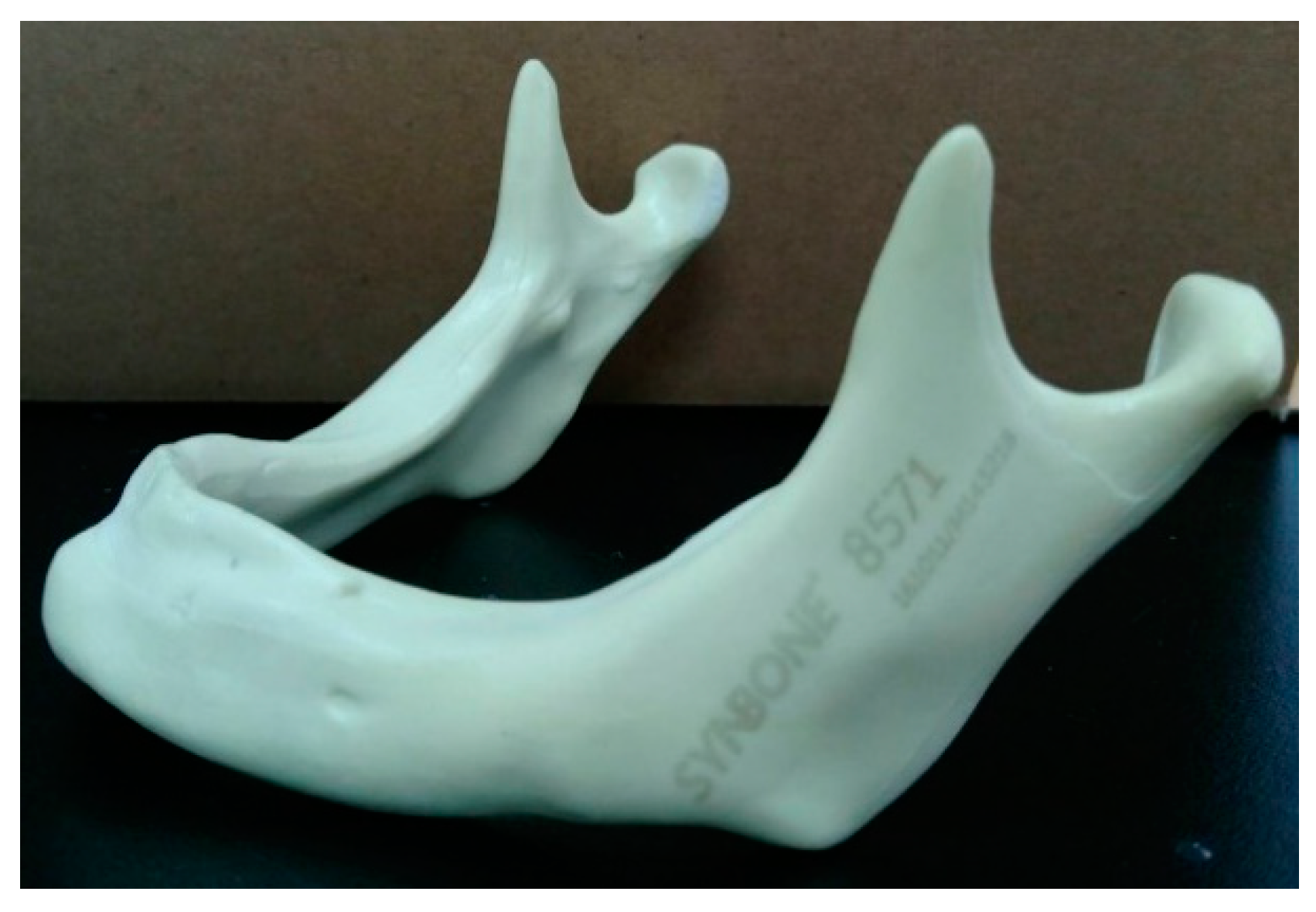
2.1. Processing of 3D STL (Stereolithography) Mandibular Model

Mandible images were taken from an artificial edentulous bone model with the anatomical appearance of the human mandible (#8571, Synbone, Malans, Switzerland; Figure 1). A dental CT device (NewTom VGi-MF scanner, QR, Verona, Italy) was used to capture a series of 0.2-mm Digital Imaging and Communications in Medicine format CT images. These images were then imported into the medical image processing software Mimics (version 15, Materialise, Leuven, Belgium) for the purposes of differentiating the contours of the mandible and constructing a 3D STL mandible model with both the cortical and trabecular mandibular bones; while constructing the model, the thickness of the cortical bones was adjusted averagely to 2 mm.

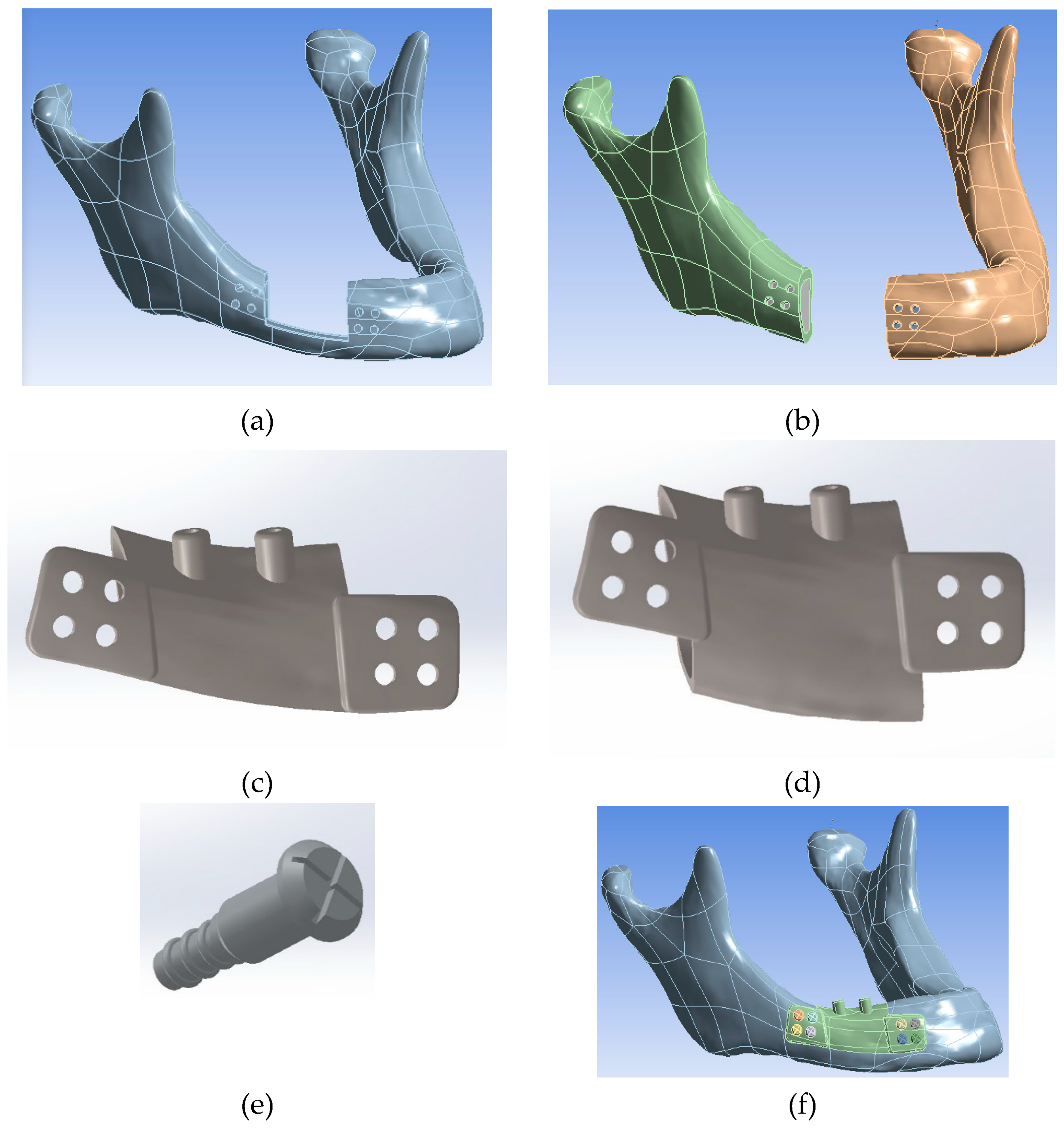
2.2. 3D Modeling of Computer-Aided Design (CAD) Solid Model

The software SpaceClaim (Swanson Analysis Inc., Huston, PA, USA) was used to construct the polygonal surface of the STL model and to add volume to the interior of the mandible, ultimately transforming the STL mandibular model into a 3D solid mandibular model. With regard to the design of the 3D-printed Ti-alloy mandibular implants, the software Geomagic Design X6 (Geomagic Inc., Morrisville, NC, USA) was used to draw the design plans in this study. First, resection procedures were performed on the right mandibular bone according to two predetermined severity levels of mandibular defect: resection that retains the residual right mandibular bone (for patients with mild oral cancer) and complete resection of the right mandibular bone (for patients with severe oral cancer), as shown in Figure 2a,b, respectively. Subsequently, the designs of the 3D-printed Ti-alloy mandibular implants were determined according to the different levels of mandibular resection.
For the design of the 3D-printed Ti-alloy mandibular implants, three main entities must be considered, namely the main body of the implant, the left-wing plate with screw holes, and the right-wing plate with screw holes. The main body of implant contained the metal reconstruction of a missing mandible bone and a restorative basal seat (for future placement of dental crowns). For the wing plate with screw holes, it was used to fix the entire 3D-printed structure to the bone with screws. In this study, the outer appearances of the 3D printed mandibular implants were designed based on two severity levels of the mandibular defect—Model 1 and Model 2 (Figure 2c,d). To prepare for the possible placement of a dental crown in the future, the implants for both models were equipped with spherical shaped abutments (5 mm in diameter) that had an unsplinted system of restorative basal seat.
Eight bone screws (Figure 2e) were also designed to be fixed respectively on the left- and right-wing plates to secure the main body of implant on the defective area of the mandible (Figure 2f). Regarding the design parameters for the Model 1 and Model 2 implants, two implant lengths were adopted, namely 20 and 25 mm (Figure 3a,b); whereas, for the thickness of the implant, three implant lengths were adopted, namely 0.8, 1.0, and 1.5 mm (Figure 3c–e). Therefore, a total of 12 different CAD solid models with varying design parameters were available for numerical analysis in this study.

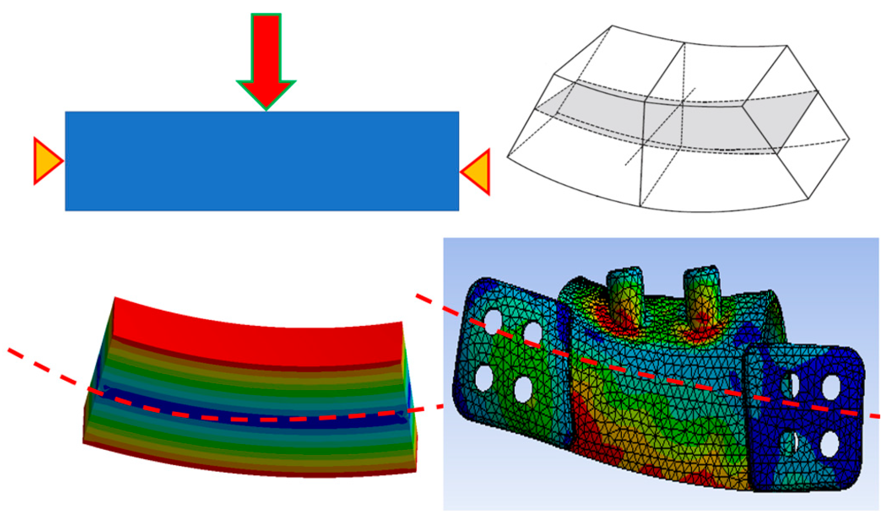
2.3. Finite Element Simulation

After the designs for the 12 solid models were completed, each model and its screw details were loaded into the FE analysis software, ANSYS Workbench (Swanson Analysis Inc., Huston, PA, USA), for the construction of FE meshes. Thus, 3D FE models were constructed (Figure 4a). The element sizes of screws, 3D-printed mandibular implants, cortical bone, and trabecular bone were 0.3, 0.8, 1, and 1.5 mm, respectively.
The properties of the materials used in this study were specified with reference to relevant studies and technical reports [16,17]. The material properties for the cortical bones, cancellous bones, Ti-alloy screws, and 3D-printed Ti-alloy mandibular implants were set to be homogenous and linear (Table 1). The loading conditions were as illustrated in Figure 4b; an oblique force of 100 N was applied at 45° to the lingual–buccal direction [18]. The boundary conditions were as illustrated in Figure 4b; the X, Y, and Z direction of the temporomandibular joint surface were fixed [15]. In this study, the von Mises stress was selected as the index for the evaluation of (1) peak stress values and (2) stress distribution of the implant and its surrounding bones in those 12 models.

3. Results

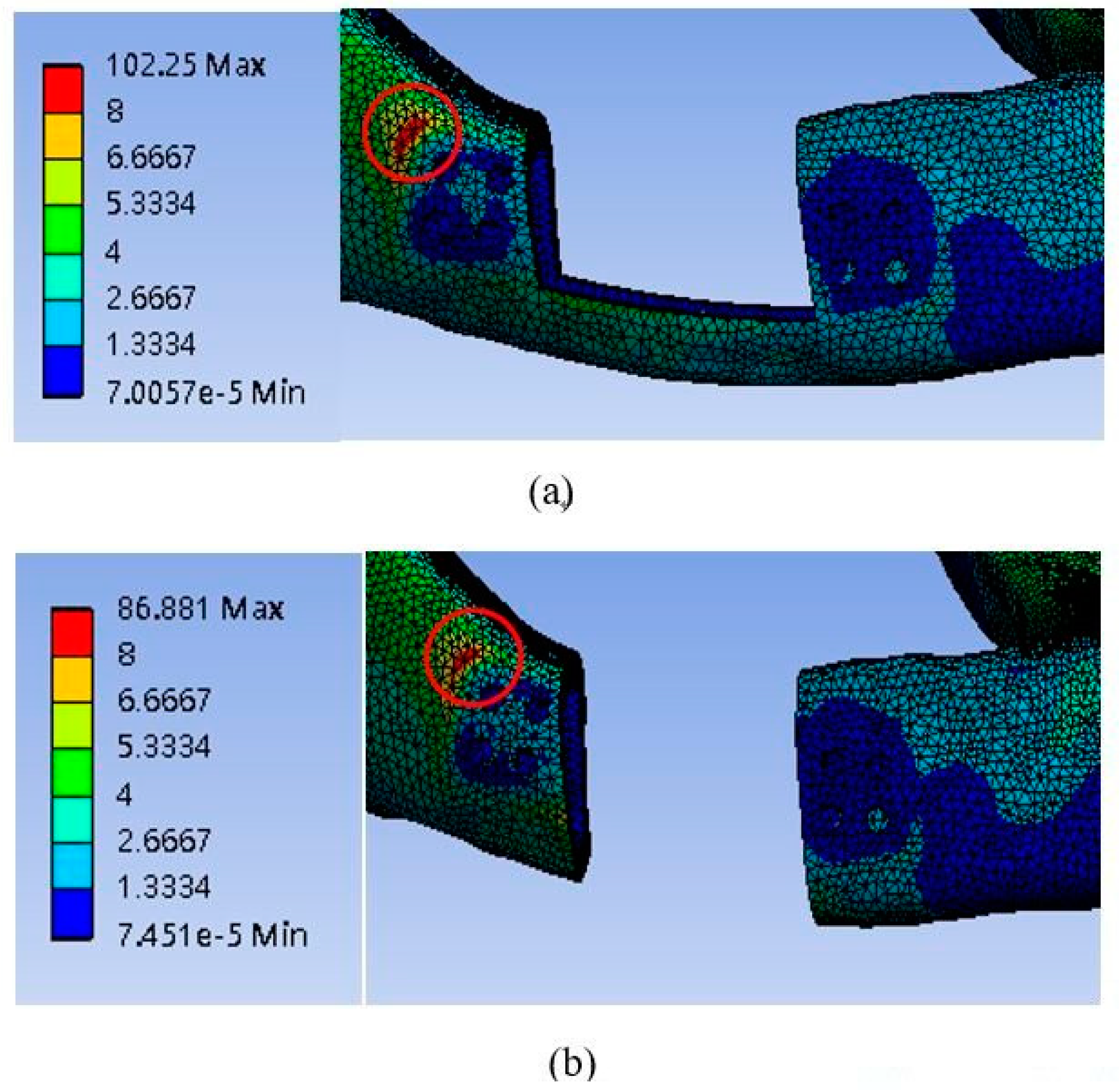
3.1. Mandibular Implant Stress

For both Model 1 and Model 2, high stress was detected at two spots on the implant (Figure 5): (1) the lower edge of the abutment and (2) the lower edge of the implant body near the right-wing plate. According to the material properties provided by the manufacturer [17], the tensile strength of the 3D-printed Ti-alloy was about 1030 MPa, which was much higher than the peak stresses of 3D-printed mandibular implants in all the models.
The analyzed high-stress values of the 12 implant models are presented in Table 2. The highest stress value was recorded in Model 2 at a thickness of 0.8 mm: when the length was 20 mm, the stress at the lower edge of the abutment was 56.67 MPa, and when the length was 25 mm, the stress at the lower edge of the implant body was 52.95 MPa, which was the second highest stress value. Regardless of whether the implant body length was 20 mm (56.67 MPa) or 25 mm (52.95 MPa), the highest stress value was always detected at the intersection of the main implant body and right-wing plate. The lowest high-stress value (24.80 MPa) was recorded in Model 2 at a thickness of 1.5 mm and a length of 20 mm. At the same length and thickness, the second lowest high-stress value was recorded (25.84 MPa) in Model 1.

3.2. Cortical Bone Stress

For both Model 1 and Model 2, high stress was detected in the area close to the bone screws on the right-upper side of the implant (Figure 6).
The high-stress values for the cortical bone near the 3D-printed implant are presented in Table 3. The highest cortical bone stress near the 3D-printed implant (13.37 MPa) was recorded in Model 1 at a thickness of 1.5 mm and a length of 20 mm. The second highest stress value (12.16 MPa) was recorded in Model 2, also at a thickness of 1.5 mm and a length of 20 mm. The third highest stress value (11.91 MPa) was found in Model 1 at a thickness of 1.5 mm and a length of 25 mm. The fourth highest cortical bone stress value (11.51 MPa) was found in Model 2 at a thickness of 1.5 mm and a length of 25 mm.
The lowest cortical bone high-stress value (10.07 MPa) was recorded in Model 2 at a thickness of 0.8 mm and a length of 25 mm. The second lowest high-stress value (10.51 MPa) was found in Model 2 at a thickness of 0.8 mm and a length of 20 mm.

4. Discussion

The application of 3D printing is increasing in popularity. This technology provides several benefits and also promotes the advancement of modern medicine, for example, customized or patient-matched 3D-printed implants. The important goal of this study was to use the computer simulation (FE analysis) to investigate the possibility of application of 3D-printed Ti-alloy mandibular implant and evaluate how the stresses of the implant and the bone near the implant changed when the implant designs (including the appearance of the implant and its thickness or length) were altered.

4.1. Comparing the Two Implant Designs

The results revealed that for both types of implants, the highest stress values in the implants’ interiors were typically found in two locations: (1) the lower edge of the abutment and (2) the intersection of the main implant body and right-wing plate. To understand why the stress was concentrated at these two points, imagine the overall structure of the implant as a three-point bending sample. As shown in Figure 7, when a force is exerted from above and the two lateral sides are constant (i.e., the X, Y, and Z directions are locked), the stress along the neutral axis (i.e., the middle section of the sample) should be lower, whereas high stress should be detected above and below the neutral axis. The designs of the 3D-printed Ti-alloy mandibular implants in this study were identical to the working principles of a three-point bending sample (especially for Model 1). Therefore, stress was lower on the implant, with the high-stress spots being located at the lower edge of the abutment (i.e., above the neutral axis) and below the implant body (i.e., below the neutral axis).
The results obtained from comparing the two implant designs indicated that the implant design that required complete resection of the right mandibular bone (Model 2) caused higher stress in the implant body (Table 2), therefore, transmitted the less stress into the bone. This resulted in a lower stress value of the bone around the implant with the full mandibular resection due to the effects of stress shielding. A similar situation has also been occurred in the other orthopedic implants and may lead to bone atrophy [19,20,21]. That might be a shortcoming of this kind of implant that future studies should seek to fix if it is available in the clinical application.

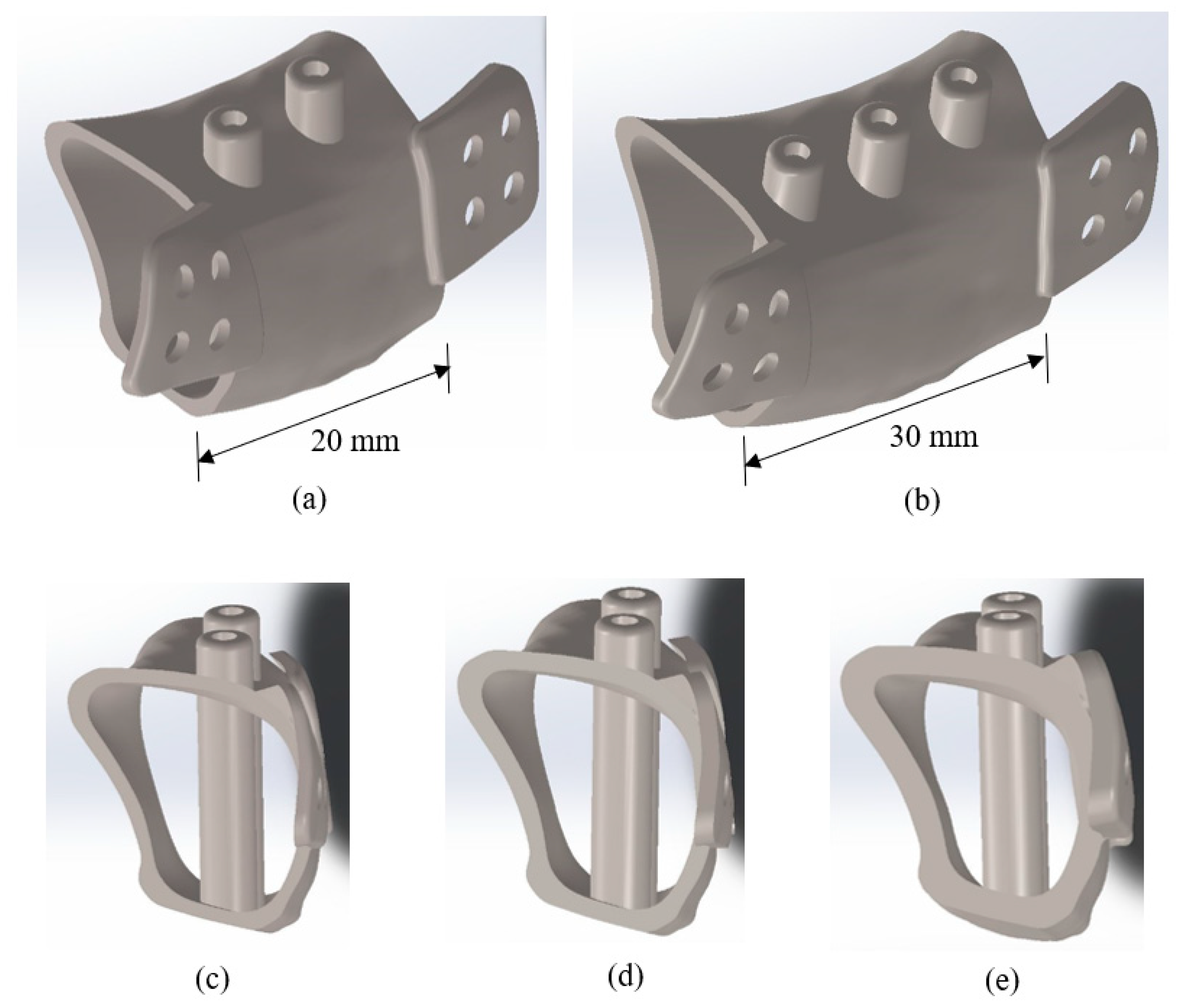
4.2. Implant Body Length and Body Thickness

According to the results of this study, adopting a longer implant body length could help reduce stress on the bones that surrounded the 3D-printing implant. Taking two of the Model 1 implants as an example, the measured surrounding bone stress value for the implant with a length of 22 mm and a thickness of 0.8 mm was 11.79 MPa, which was 10% lower than the surrounding bone stress value for the implant with a length of 25 mm. By contrast, the results indicated that implant body length did not have a consistent effect on the stress value of the implant body. For example, in the high-stress zones located at the lower edge of the main implant body near the right-wing plate, adopting a shorter implant length of 20 mm resulted in a higher stress value. However, in the high-stress zone at the lower edge of the abutment, adopting a longer implant length of 25 mm also resulted in a higher stress value.
Regarding the influence of the implant body thickness, the results revealed that for both models, the measured stress values were highest for the 0.8-mm implants, followed by the 1.0- and 1.5-mm implants. These results indicated that the stress sustained by the implant’s interior reduced as the thickness increased. A possible explanation for this is that the increased thickness could disperse the stress sustained by the implant’s interior. However, for the stress values of the bones surrounding the implant, the findings revealed that the stress values were largest for the 1.5-mm implants, followed by the 1.0-mm implants, and lastly the 0.8-mm implants. These results suggest that thicker implants cause the surrounding bones to be subjected to higher stress levels, with the stress on the implant body and stress on the surrounding bones affecting each other. Adopting a thicker implant may appear to reduce the stress sustained by the implant; however, doing so actually means transferring the stress to the surrounding bones. Therefore, when designing a 3D-printed mandibular implant for a patient with a mandibular defect, the strength of the patient’s bones may need to be considered. Additionally, to ensure that each patient receives the optimal medical care, engineers and/or clinicians must refine the designs of 3D-printed implants based on the differential conditions of each patient.

4.3. Limitations and Future Work

This study has several limitations. For example, the settings used for the loading and boundary conditions during the FE simulation were limited. The loading condition was simplified to a single force, and the boundary condition was set to be fixed at specific locations. Future studies should apply localized multiple-bite forces as the loading conditions and incorporate muscle attachments as the boundary conditions. In addition, the material properties of bone are simplified to be linear and isotropic. However, the material properties of bone are closer to be anisotropic and inhomogeneous; therefore, those conditions can be adopted in the future study to bring the results closer to the real clinical situation.
According to the analyzed parameters of the current study, the researchers used the additive manufacturing process through a Renishaw AM 400 system (Renishaw Plc., Wharton Anderch, UK) as selective laser melting equipment for successfully producing the 3D-printed titanium-alloy reconstruction/prosthetic framework for the mandibular segmental osteotomy defect (Figure 8). More in-depth in vitro experiments or clinical research using these models should be conducted in the future.

5. Conclusions

Generally, the stress of implants that required complete resection of the right mandibular bone (Model 2) was higher than that of implants that retained the residual right mandibular bone (Model 1). In the high-stress zone at the lower edge of the abutment, the stress of implants with a length of 25 mm was higher than that of implants with a length of 20 mm. However, in the high-stress areas at the lower edge of the implant body near the right-wing plate, the stress of implants with a length of 20 mm was higher than that of those with a length of 25 mm.
Implant stress decreased as implant thickness increased. However, an opposite trend was detected in the cortical bone; that is, cortical bone stress increased as implant thickness increased. Additionally, a decrease in implant length resulted in a slight increase in cortical bone stress.

Author Contributions

Conceptualization, Y.-W.S. and L.-J.F.; data curation, S.-N.H.; formal analysis, S.-N.H., M.-Y.S., and H.-L.H.; funding acquisition, H.-L.H. and L.-J.F.; investigation, S.-N.H., J.-T.H., H.-L.H., and L.-J.F.; methodology, M.-Y.S., Y.-W.S., and H.-L.H.; resources, M.-Y.S., Y.-W.S., J.-T.H., H.-L.H., and L.-J.F.; supervision, H.-L.H. and L.-J.F.; validation, S.-N.H., H.-L.H., and L.-J.F.; writing—original draft, S.-N.H. and H.-L.H.; writing—review and editing, M.-Y.S., H.-L.H., and L.-J.F.

Funding

This research was supported by the Ministry of Science and Technology (MOST 105-2314-B-039-029 and MOST 107-2221-E-039-007) of Taiwan.

Conflicts of Interest

The authors declare no conflict of interest.

References

  1. Foster, R.D.; Anthony, J.P.; Sharma, A.; Pogrel, M.A. Vascularized bone flaps versus nonvascularized bone grafts for mandibular reconstruction: An outcome analysis of primary bony union and endosseous implant success. Head Neck 1999, 21, 66–71. [Google Scholar] [CrossRef]
  2. Hidalgo, D.A.; Swartz, W.M. Aesthetic Improvements in Free-Flap Mandible Reconstruction. Plast. Reconstr. Surg. 1991, 88, 574–585. [Google Scholar] [CrossRef] [PubMed]
  3. Goh, B.T.; Lee, S.; Tideman, H.; Stoelinga, P.J. Mandibular reconstruction in adults: a review. Int. J. Oral Surg. 2008, 37, 597–605. [Google Scholar] [CrossRef] [PubMed]
  4. Cohen, A.; Laviv, A.; Berman, P.; Nashef, R.; Abu-Tair, J. Mandibular reconstruction using stereolithographic 3-dimensional printing modeling technology. Oral Surg., Oral Med., Oral Pathol., Oral Radiol., Endod. 2009, 108, 661–666. [Google Scholar] [CrossRef] [PubMed]
  5. Mehra, P.; Miner, J.; D’Innocenzo, R.; Nadershah, M. Use of 3-D Stereolithographic Models in Oral and Maxillofacial Surgery. J. Oral Surg. 2011, 10, 6–13. [Google Scholar] [CrossRef] [PubMed] [Green Version]
  6. Parthasarathy, J. 3D modeling, custom implants and its future perspectives in craniofacial surgery. Ann. Surg. 2014, 4, 9–18. [Google Scholar] [CrossRef] [PubMed] [Green Version]
  7. BBC. Transplant Jaw Made by 3D Printer Claimed as First. Available online: http://www.bbc.co.uk/news/technology-16907104 (accessed on 8 March 2012).
  8. Mohammed, M.I.; Fitzpatrick, A.P.; Gibson, I. Customised design of a patient specific 3D printed whole mandible implant. KnE Eng. 2017, 2, 104–111. [Google Scholar] [CrossRef]
  9. Popov, V.V.; Muller-Kamskii, G.; Kovalevsky, A.; Dzhenzhera, G.; Strokin, E.; Kolomiets, A.; Ramon, J. Design and 3D-printing of titanium bone implants: Brief review of approach and clinical cases. Biomed. Eng. Lett. 2018, 8, 337–344. [Google Scholar] [CrossRef] [PubMed]
  10. Ackland, D.C.; Robinson, D.; Redhead, M.; Lee, P.V.S.; Moskaljuk, A.; Dimitroulis, G. A personalized 3D-printed prosthetic joint replacement for the human temporomandibular joint: From implant design to implantation. J. Mech. Biomed. Mater. 2017, 69, 404–411. [Google Scholar] [CrossRef] [PubMed]
  11. Dawood, A.; Marti, B.M.; Sauret-Jackson, V.; Darwood, A. 3D printing in dentistry. Br. Dent. J. 2015, 219, 521–529. [Google Scholar] [CrossRef] [PubMed]
  12. Sutradhar, A.; Park, J.; Carrau, D.; Nguyen, T.H.; Miller, M.J.; Paulino, G.H. Designing patient-specific 3D printed craniofacial implants using a novel topology optimization method. Med. Biol. Eng. Comput. 2016, 54, 1123–1135. [Google Scholar] [CrossRef] [PubMed]
  13. Shaoki, A.; Xu, J.-Y.; Sun, H.; Chen, X.-S.; Ouyang, J.; Zhuang, X.-M.; Deng, F.-L. Osseointegration of three-dimensional designed titanium implants manufactured by selective laser melting. Biofabrication 2016, 8, 045014. [Google Scholar] [CrossRef] [PubMed]
  14. Jahadakbar, A.; Moghaddam, N.S.; Amerinatanzi, A.; Dean, D.; Karaca, H.E.; Elahinia, M.; Wang, G.-J. Finite Element Simulation and Additive Manufacturing of Stiffness-Matched NiTi Fixation Hardware for Mandibular Reconstruction Surgery. Bioengineering 2016, 3, 36. [Google Scholar] [CrossRef] [PubMed]
  15. Dahake, S.; Kuthe, A.; Kulkarni, S.; Mawale, M. Finite element analysis of customized implant in mandibular reconstruction after tumor resection with and without using customized surgical osteotomy guide. Int. J. Med. Rob. Comput. Assisted Surg. 2018, 14, e1854. [Google Scholar] [CrossRef] [PubMed]
  16. Geng, J.-P.; Tan, K.B.; Liu, G.-R. Application of finite element analysis in implant dentistry: A review of the literature. J. Prosthet. Dent. 2001, 85, 585–598. [Google Scholar] [CrossRef] [PubMed] [Green Version]
  17. Renishaw. Ti6Al4V ELI-0406 Powder for Additive Manufacturing. Available online: https://resources.renishaw.com/en/details/data-sheet-ti6al4v-eli-0406-powder-for-additive-manufacturing--94700 (accessed on 22 May 2019).
  18. Huang, H.-L.; Huang, J.-S.; Ko, C.-C.; Hsu, J.-T.; Chang, C.-H.; Chen, M.Y.C. Effects of splinted prosthesis supported a wide implant or two implants: A three-dimensional finite element analysis. Clin. Oral Implant. 2005, 16, 466–472. [Google Scholar] [CrossRef] [PubMed]
  19. Nagels, J.; Stokdijk, M.; Rozing, P.M. Stress shielding and bone resorption in shoulder arthroplasty. J. Shoulder Elbow Surg. 2003, 12, 35–39. [Google Scholar] [CrossRef] [PubMed]
  20. Sumner, D. Long-term implant fixation and stress-shielding in total hip replacement. J. Biomech. 2015, 48, 797–800. [Google Scholar] [CrossRef] [PubMed]
  21. Sing, S.L.; An, J.; Yeong, W.Y.; Wiria, F.E. Laser and electron-beam powder-bed additive manufacturing of metallic implants: A review on processes, materials and designs. J. Orthop. Res. 2016, 34, 369–385. [Google Scholar] [CrossRef] [PubMed]
Figure 1. Synbone manufactured artificial edentulous mandibular bone model (model number: 8571).
Metals 09 00597 g001
Figure 2. Resection conditions of the two mandibular defects modelled in this study—(a) mild oral cancer and (b) severe oral cancer. Based on these conditions, two designs of 3D-printed Ti-alloy mandibular implants were conducted—(c) Model 1 and (d) Model 2. Computer-aided design (CAD) models of (e) bone screws were used to (f) secure the 3D-printed Ti-alloy mandibular implant on the defective area of the mandible (Model 1 was shown as example).
Metals 09 00597 g002
Figure 3. Using Model 2 as an example: (a) implant body length of 20 mm; under this length, two abutments are allocated; (b) implant body length of 30 mm; under this length, three abutments are allocated; (c) implant body thickness of 0.8 mm; (d) implant body thickness of 1.0 mm; and (e) implant body thickness of 1.5 mm.
Metals 09 00597 g003
Figure 4. (a) FE model of Model 1. (b) The temporomandibular joint is the region specified by the boundary conditions (blue area). (c) Oblique occlusal force (100 N) was applied above the abutment (the red arrow).
Metals 09 00597 g004
Figure 5. Von Mises stress distribution of the implant: (a) Model 1 (length: 20 mm; thickness: 0.8 mm) and (b) Model 2 (length: 20 mm; thickness: 0.8 mm) (Unit: MPa).
Metals 09 00597 g005
Figure 6. Von Mises stress distribution of the cortical bones near the 3D-printed implant in (a) Model 1 (length: 20 mm; thickness: 0.8 mm) and (b) Model 2 (length: 20 mm; thickness: 0.8 mm) (Unit: MPa).
Metals 09 00597 g006
Figure 7. Geometry and loading conditions of the three-points-bending model (upper level) and the stress distributions of the three-points-bending model (lower left) and Model 1 (lower right).
Metals 09 00597 g007
Figure 8. (a) A 3D-printed Ti-alloy reconstruction sample was constructed by referring to CAD model of Model 1 (length: 20 mm; thickness: 0.8 mm) and (b) was well placed in the defect of the artificial mandible.
Metals 09 00597 g008
Table 1. Material properties used in the finite element (FE) model [17,18].
MaterialYoung’s Modulus E (MPa)Poisson’s Ratio ν
Cortical bone13,4000.3
Trabecular bone7900.3
Titanium alloy screw (Ti-6Al-4V) 110,0000.35
3D printing titanium alloy (Ti-6Al-4V)129,0000.34
Table 2. High-stress values at different points on the implant body.
Model #High Stress Position 20 mm25 mm
Model 1Lower edge of the abutment0.8 mm35.53 MPa46.68 MPa
1 mm32.35 MPa38.93 MPa
1.5 mm25.18 MPa31.69 MPa
Lower edge of the implant body near right-wing plate 0.8 mm46.83 MPa41.10 MPa
1 mm50.52 MPa40.34 MPa
1.5 mm38.32 MPa35.03 MPa
Model 2Lower edge of the abutment0.8 mm33.56 MPa38.91 MPa
1 mm30.17 MPa36.65 MPa
1.5 mm24.80 MPa25.84 MPa
Lower edge of the implant body near left-wing plate0.8 mm56.67 MPa52.95 MPa
1 mm46.02 MPa42.75 MPa
1.5 mm38.37MPa33.00 MPa
Table 3. High-stress values of the mandibular cortical bones, the cortical bone near the 3D-printed implant.
Model # 20 mm25 mm
Model 10.8 mm11.79 MPa10.59 MPa
1 mm 12.02 MPa11.16 MPa
1.5 mm13.37 MPa11.91 MPa
Model 20.8 mm10.51 MPa10.07 MPa
1 mm11.29 MPa11.05 MPa
1.5 mm12.16 MPa11.51 MPa

