Article

Materials Properties and Liquid Flow in the Hearth of the Experimental Blast Furnace

1
Process Metallurgy Department, SWERIM AB, SE-97125 Luleå, Sweden
2
Department of Civil, Environmental and Natural Resources Engineering, Luleå University of Technology, SE-97187 Luleå, Sweden
*
Author to whom correspondence should be addressed.
Metals 2019, 9(5), 572; https://doi.org/10.3390/met9050572
Submission received: 19 April 2019 / Revised: 7 May 2019 / Accepted: 13 May 2019 / Published: 17 May 2019

Abstract

:
The materials’ properties in the hearth of the blast furnace are very crucial for the hearth conditions. In this study, a number of coke, slag, metal, and aggregate samples were collected from the hearth of the LKAB’s experimental blast furnace (EBF). Subsequently, the coke, slag, and metal samples were chemically analyzed by X-ray fluorescence (XRF) or optical emission spectrometer (OES); the aggregate samples were analyzed by scanning electron microscope combined with energy-dispersive X-ray spectroscopy (SEM/EDS). The possible flow field of the liquid in the EBF hearth before quenching is depicted according to Cu tracers in the metal samples. Selected elements in the coke, slag, and metal were mapped for two sampling layers in the hearth, as well as in one cross section of the flow field. The results indicate that there exists an area beneath, and in front of, tuyere 3, where the flow resistance of the liquid was high. The high flow resistance contributed to the formation of a cold zone in the close-to-wall region and at the bottom of the EBF hearth. The temperature distribution in the EBF hearth has significant impacts on the chemical properties of the materials in different positions of the EBF hearth, as well as on the radial and vertical distributions of certain elements/components.

1. Introduction

The hearth of the blast furnace (BF) has been a research topic in a large number of studies, as the hearth conditions, among others, determines the liquid drainage, the energy consumption, the hot metal quality, the hot metal productivity and the wear of the refractory linings [1,2,3,4,5]. In the hearth of the BF the materials are mainly composed of coke, molten slag and hot metal. The coke in the hearth forms a cone-shaped coke pile (named as dead-man), which allows the molten slag and hot metal to flow in-between the coke lumps. During the flow, heat transfer, and materials transfer take place, due to the flow of the hot liquids and the chemical interactions among the hearth materials. These transfers could lead to various material phenomena in the hearth of the BF, such as carburization of hot metal, recirculation of the alkali in the hearth [6], reduction of FeO in the slag [7], radial/vertical variations of slag basicity, and certain elements in the hearth of the BF [8]. In turn, the materials phenomena, such as the molten slag/hot metal compositions, the void fraction, and the size of the coke bed, can influence liquid flow, and thus influence heat and material transfers.
The LKAB’s experimental blast furnace (EBF) is a unique tool used to optimize the ferrous pellets, as well as the ironmaking process. It has one tap-hole, three tuyeres placed with 120° separation, and a working volume of 8.2 m3. The diameters at tuyere level and hearth level are 1.2 m, and 1.4 m, respectively. The working height from tuyere level to stock lime is around 6 m. Although EBF is quite small, the operation of the EBF is similar as commercial blast furnaces. More detailed information of the EBF is available in the literature [9].
In the end of the EBF campaigns, sampling into the hearth has often been carried out by core-drilling into the EBF’s hearth [10,11,12]. After campaign 32, a large number of samples were collected by core-drilling and a large set of coke, slag, and metal samples became available for chemical analysis. Further, the Cu-tracer, injected before quenching of the EBF, was dissolved in the metal, and made it possible to identify the flow field of the liquid in the EBF hearth.
In this study, mapping of the selected elements/components were conducted, based on the chemical analysis results of coke, slag, metal, and aggregate samples collected from the EBF hearth. The purpose is to provide a comprehensive understanding of the liquid flow and its interaction with solid coke in the hearth of EBF. New knowledge will contribute to the understanding of hearth conditions.

2. Methodology

2.1. EBF Campaign 32

The EBF campaign 32 was conducted from September to November in 2016. During the campaign, LKAB’s olivine pellets (MPBO pellets, 9–12.5 mm) was used as iron-bearing material. Quartzite, BOF slag, and limestone (10–20 mm) were used as slag formers. The used coke is similar as that used in the industrial process but with a smaller particle size (15–30 mm). The blast flow rate was 1550 Nm3/h and the temperature of the blast was 1200 °C. The production rate was around 1.5 tHM/h and the slag volume was around 145 kg/tHM. The average consumption data (two weeks prior to quenching) for the solid materials charged into the EBF are shown in Table 1.

2.2. Copper Injection in the End of EBF Campaign 32

In the end of EBF campaign 32, just before quenching, 1.5 kg pulverized copper was injected through the coal injection lance in tuyere 3. The position of the tuyere 3, relative to the other two tuyeres and the taphole, is shown in Figure 1. During the copper injection, the coal injection through tuyere 3 was interrupted, as the copper injection device was mounted to the coal injection lance. After finalizing the copper injection coal injection was restarted. In the end of the campaign a final tapping of hot metal and slag was made and then the EBF was quenched with nitrogen. The total time, from copper injection to the final tapping, was around 21 min.

2.3. Collection of Samples from the EBF Hearth

When the EBF had been cooled down to room temperature and the excavation of the EBF down to tuyere level was finalized, the hearth was detached. Steel tubes (diameter 130 mm and length 500 mm) were drilled into the coke bed in the hearth to collect the core-drilling samples. These samples were collected from two layers and various positions (with respect to positions of the three tuyeres and taphole) in the hearth of EBF as shown in Figure 1. In total 7 core-drilling tubes were obtained from the first core-drilling layer, and 21 from the second core-drilling layer.
In Figure 1, it is seen that some core-drilling tubes, especially from the second core-drilling layer, are protruding above the bed level. This is due to the presence of hard materials, essentially metal and metal-containing aggregates, which hindered the core drilling further down into the bed. Therefore, some of the drilling tubes were not fully filled with samples. When the drilled cores from the second core-drilling layer had been taken out, 3 samples were also taken manually by hands. The relative positions (with respect to the depth into the hearth) of the collected core-drilling samples as well as the manual samples are shown in Figure 2.

2.4. Analysis of the Samples

The samples in each core-drilling tube were divided into 5 sub-samples (10 cm in length each). Since some tubes were not fully filled with samples, only 104 sub-samples were available, as shown in Figure 2. Each sub-sample was screened into >16mm, 10–16 mm, 5–10 mm, 2.8–5 mm, 1–2.8 mm, 0.5–1 mm and <0.5 mm fractions. The >5 mm fractions were manually separated into the metal, coke, slag and aggregate with the aid of a magnet. In this study, the coke, slag, and metal samples from the 5–10 mm fractions were selected for further study. This is mainly because the materials in this fraction are quite dominant in amount, and can be easily separated from one to another, and thus can be used as representative samples. Coke and slag samples from the 5–10 mm fraction were ground into fines (<1 mm) and analyzed by wavelength dispersive X-ray fluorescence (WD-XRF, model ARL 9900 produced by Thermo Fisher Scientific, Waltham, MA, USA). Metal samples from the 5–10 mm fraction were remelted and analyzed by optical emission spectrometer (OES, model ARL 4460 produced by Thermo Fisher Scientific, Waltham, MA, USA). Carbon in the coke and metal samples, as well as ash content in the coke samples, were determined by a combustion and IR detection method (LECO CS-444, St. Joseph, MO, USA). In total 28 coke samples, 28 slag samples, and 101 metal samples from the EBF hearth were selected for XRF or OES analysis, as shown in Figure 2. Additionally, the original coke used for the EBF campaign was also analyzed by XRF. The chemical analysis results from the samples are graphically presented in the paper by applying color gradation to show the values. The estimated uncertainty for C analysis is < 3.5% and the estimated uncertainty for the analysis of other elements is < 10%. Due to the properties (a mix of metal, slag and coke) of the manual samples, the manual samples were analyzed by scanning electron microscope combined with energy-dispersive X-ray spectroscopy (SEM/EDS, Zeiss Merlin FEG-SEM, Jena, Germany) instead. Before the analysis, those manual samples were prepared by casting in epoxy resin, grinding, and polishing.

3. Results and Discussion

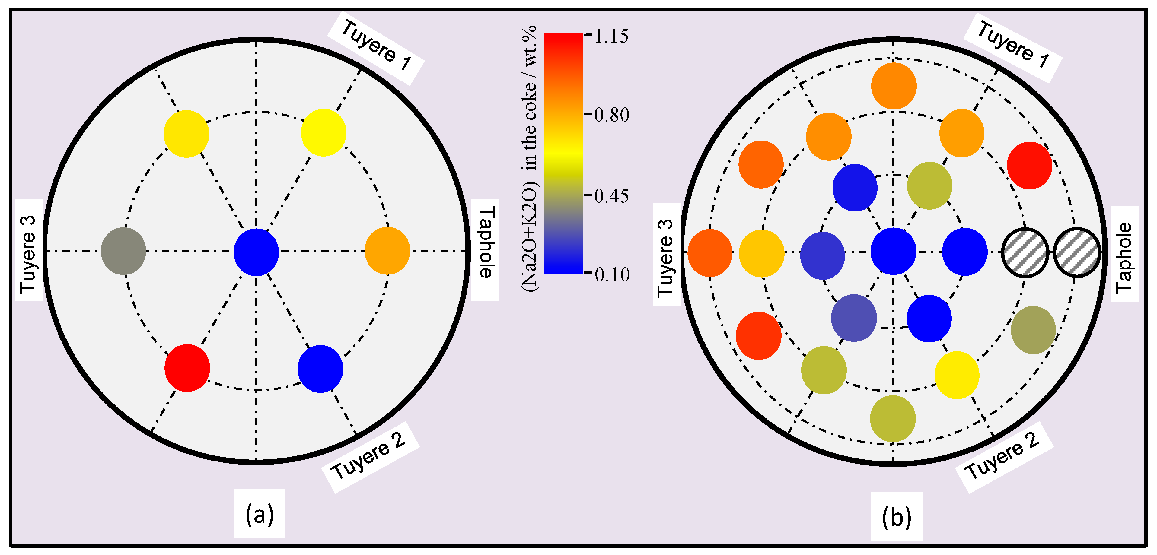
3.1. Properties of the Coke

In the original coke used in the EBF it contains 7.1 wt% SiO2 and 3.1 wt% Al2O3; the ash content of the coke is 11.4 wt.%. In the coke collected from the hearth of the EBF, the chemical compositions vary with the sampling positions. Compared to the original coke, the ash contents in the coke, collected from the hearth of the EBF are higher, as shown in Figure 3. Further, the ash contents in the coke shows vertical and radial variations, as in general, the ash contents are higher in the coke samples collected from the second core-drilling layer than those from the first core-drilling, and higher in the coke samples collected from the close-to-wall region than those from the center. The increase of ash in the coke can be attributed to degrading of the coke in the EBF, and due to the penetration of the molten slag and hot metal into the coke.
During the EBF operation, some alkali (Na2O and K2O) could be retained in the lower part of the BF. Figure 4 shows the alkali retention in the hearth of the EBF, according to the alkali contents in the coke samples. It is seen that the alkali in the coke also shows vertical and radial variations: higher alkali contents were found in the second core-drilling layer and the close-to-wall region. In the BF, the alkali retention in the slag was influenced by the slag basicity and temperature [6]. The consistency of alkali distribution with the coke ash distribution in the hearth could, on one hand, be due to a lower temperature in the close-to-wall region, and on the other hand, be due to the variation of the ash content, which changes the alkali capacity of the coke.

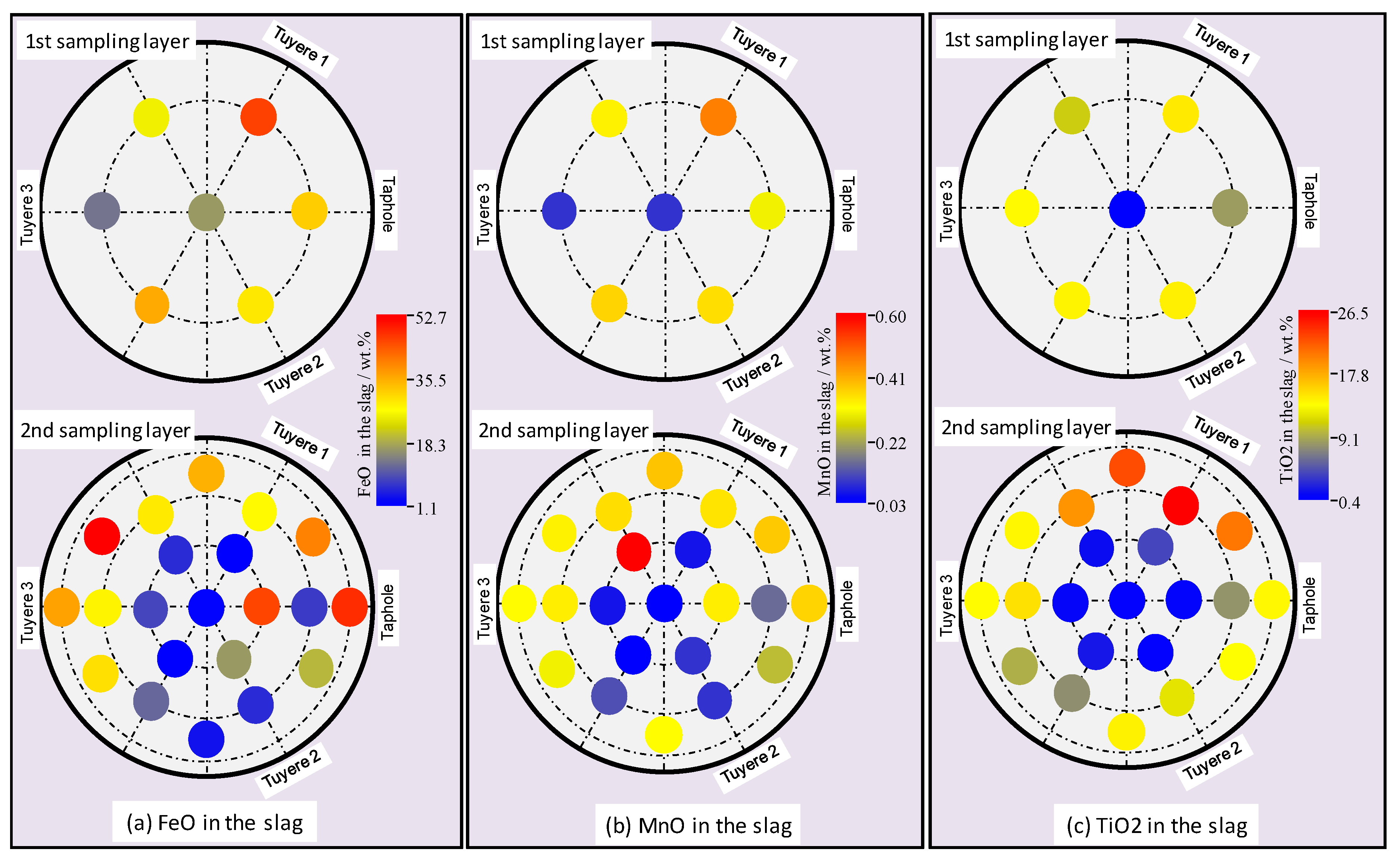
3.2. Properties of the Slag

Figure 5a,b show the basicity (wt.%CaO/wt.%SiO2) and alkali content (Na2O + K2O), respectively, of the slag in the two sampling layers. It is seen that the basicity, and alkali contents of the slag, also show vertical and radial variations in the EBF hearth; however, the distributions of the slag basicity and alkali contents behave differently. The slag samples from the first sampling layer and those from the center have higher basicity, while the slag samples from the first sampling layer and those from the center have lower alkali contents. This may be due to the high dependence of the alkali capacity on the slag basicity. Further, it is also seen that the vertical and radial distributions of the alkali in the slag follow similar trends as those of the alkali in the coke (as shown earlier in Figure 4). This indicates the consistency of the chemical analysis results for both coke and slag.
Similarly, the FeO, MnO, and TiO2 in the slag samples from the EBF hearth were also mapped, as shown in Figure 6. It is seen that these compounds in the EBF hearth also show vertical and radial variations, with high contents in the close-to-wall region. The high FeO and MnO distribution in the close-to-wall region may indicate a higher oxygen potential and lower temperature in the close-to-wall region. The accumulation of the titanium compounds in the close-to-wall region of the hearth was also observed in the industrial BFs [13,14]. The accumulated Ti-containing materials around the hearth wall could have two effects. Firstly, it could provide an effective protection against chemical and mechanical erosions of the hearth refractory; secondly, it could increase the viscosity of the molten slag and make it difficult to flow [13].

3.3. Properties of the Metal

Carbon and Si are important alloying elements in the hot metal. To understand the properties of the hot metal in the hearth of the EBF, C and Si contents in the metal are mapped, as shown in Figure 7. It is seen that C and Si in the metal samples do not clearly show any vertical or radial variations. Instead, there seems to be a region around the furnace wall, where the Si contents are quite low. Figure 8 shows the Mn distribution in the metal samples. It is seen that in general the Mn contents in the first sampling layer are higher than those in the second one. Further, there is a low-Mn region, which is the same as that of the low-Si-region. The low Si and low Mn in the metal samples indicate a lower heat level and higher oxygen potential.
The Cu contents in the metal samples collected from the EBF hearth are shown earlier in Figure 2. It is seen that the highest Cu contents were found in the metal samples from drilled core M105, which is located beneath and in front of tuyere 3 (the position where Cu was injected and the opposite side to the taphole). From Figure 2 it is also seen that the Cu contents in the samples collected from the close-to-wall region (M215-M221) are in general quite low. This indicates that the central part of the EBF has high permeability for hot metal and the resistance for liquid flow around the wall of the EBF hearth is higher.
According to the copper contents in the collected metal samples, the flow field of the hot metal in the EBF hearth from the position beneath tuyere 3 to the taphole can be interpreted, based on the assumption that the hot metal immediately took up copper from the injection position, and that copper in the hot metal formed a concentration gradient under the flow of the hot metal. According to the spatial distribution values of Cu in the metal samples from the EBF hearth, and by applying a maximum likelihood estimation method, the hot metal flow field is interpreted in Figure 9. It is possible that the hot metal flows vertically from a position in front of tuyere 3 to the hearth bottom, due to gravity and radially from the close-to-wall region towards the center, due to the force from blast air and the momentum of the flowing liquids towards the open taphole. Further, it is noticed that there is an area under and in front of tuyere 3, where the copper contents in the metal samples are quite low. Therefore, it is believed that beneath the combustion zones (raceways) the resistance to the flow of the liquid is higher compared to the central region of the hearth.

3.4. Properties of the Aggregates

Besides the coke, slag, and metal in the EBF hearth, a large amount of aggregates were also found, especially at the close-to-wall region and the bottom of the EBF hearth. Figure 10 shows the SEM images of the manually collected aggregate samples (referring to Figure 2 for sampling positions for manual samples). With the aid of the EDS analysis, the prevailing phases in the aggregates can be identified. It is seen that the aggregates are mainly composed of micro-sized metallic iron, slag and coke particles. In addition, Ti(C,N) crystals were also found in the aggregates. In sample MS3 (collected close to the taphole), silica was found, due to the involvement of taphole clay. In the collected aggregate samples, copper was not detected. This may indicate that the aggregates in the EBF hearth formed before quenching of the EBF. During the operation of the EBF the aggregates are believed to be stagnant, with less flow of the liquids. This will lead to the formation of cold skull around the wall of EBF hearth, due to cooling from the surroundings.

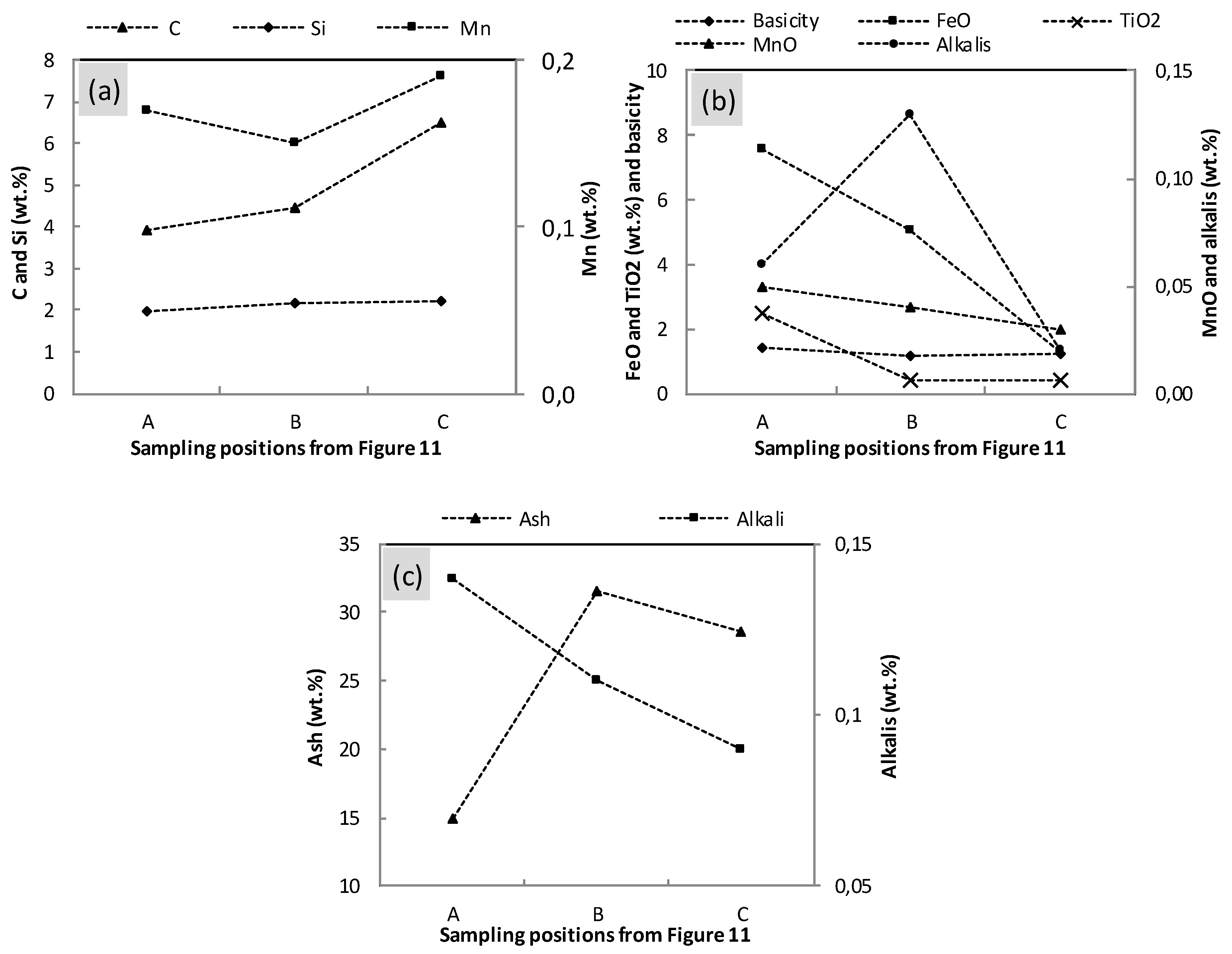
3.5. Properties of the Materials along the Flow Field in the EBF Hearth

In order to show the material properties along the flow field, a cross section of the EBF hearth (L-L view in Figure 9) is shown in Figure 11, by which the drilling cores, and the sub-samples, are also visualized. By following the variations of the Cu contents in the metal samples collected from drilled cores, a flow field of the liquid in the cross section can be deduced. Beneath the flow field, sub-samples A, B, and C (defined in Figure 11) are selected for further exploration, due to the availability of the chemical analysis results for metal, slag, and coke in these sub-samples.
Figure 12a shows the variations of C, Si, and Mn in the metal samples along the flow field. In general, it is seen that C in the metal increases along the flow from A to C, while Si is quite stable. Figure 12b shows the variations of the FeO, MnO, TiO2, slag basicity and alkali contents along the flow field. It is seen that the oxides, FeO, MnO and TiO2, in the slag decrease slightly along the flow from A to C. This could be attributed to the reduction of these oxides. No big variations in slag basicity are observed, while the variations of the alkali in the slag are of less significance, especially when the magnitude of the alkali in Figure 5a is referred to. Figure 12c shows the variations of the ash contents and the alkali contents in the coke under the influence of the liquid flow. It is seen that the ash contents in the coke increase from sampling position A to sampling positions B and C. However, the alkali contents in the coke decrease from A to C and are of less significance. This indicates that the alkali content in the coke is independent of the ash content in the coke, under the present EBF hearth conditions.

3.6. Hearth Conditions before Quenching of the EBF

The process data from the EBF campaign indicates that there was a cold zone around the wall of EBF hearth before quenching, especially in the lower part of the hearth. The formation of this cold zone is mainly caused by the significant heat loss in the surroundings, under the EBF operation conditions. However, other factors could also contribute to the formation of this cold zone. Firstly, in the hearth of the EBF, the hot liquid flows from the tuyere level, and down to the center of the hearth, leaving an area beneath and in front of the tuyeres (specifically, tuyere 3 in this study) with a low temperature, due to less heat transfer from the hot liquid. Secondly, Ti-containing compounds (such as Ti(C,N)) could have precipitated at this cold zone and built up around the wall of the EBF hearth [13]. This could also impede the flow of the hot liquid around the wall of the EBF. Thirdly, a higher amount of the coke/coal fines were generated beneath the tuyeres and the presence of the coke/coal fines could increase the resistance for the liquid flow. The mix of coke/coal fines, hot metal beads, slag, and Ti(C,N) particles in the low-temperature area could finally form the aggregate, making the hot liquid difficult to penetrate.
The presence of the cold zone, around the wall of the EBF, may lead to the retention of the alkali in the slag and coke samples at the close-to-wall region, even though it is believed that the basicity of the slag and ash contents in the coke could also influence the alkali retention. The replacement rate of coke, in the periphery and at the bottom, is slow; therefore, during excavation, it was possible to find charcoal, used during the start-up, which usually occurred 6 weeks before quenching. This means that alkali uptake can occur over time. Alkali uptake in the coke results in increased ash content but can also promote the solution loss reaction (CO2 + C = 2CO) of coke, as the alkali can work as a catalyst for this reaction [6,15]. This may justify that the coke with higher alkali content also has higher ash content, as shown earlier in Figure 3 and Figure 4. Further, the alkali in the coke can decrease the strength of the coke, making the coke lump more prone to disintegrate under the abrasion [15]. The disintegration of the coke into small pieces could reduce the void fraction in the coke bed and thus further increase the resistance for the liquid flow [16].
As shown earlier in Figure 5b, the basicity of the slag in the lower part of the EBF hearth, and at the close-to-wall region, is lower. This could probably be correlated to the higher ash content of the coke (or PCI coal) in the similar part or region. This correlation is established by considering that the higher ash content in the coke could improve the coke/slag wetting and the slag could pick up more coke ash [17]. As the silica content in the coke/coal ash is quite high, the pickup of acidic ash by slag leads to lower slag basicity.
During the operation of the EBF, the hot zone of the hearth was maintained by the continuous flow of the hot liquid from the raceway level to the lower part of the EBF hearth. Therefore, this hot zone can be represented by the flow field of the liquid. From Figure 12a,b, it is seen that the selected elements in the metal and slag vary slightly along the flow. This could be due to the continuous flow of the hot metal and slag in the hot zone during EBF operation. In Figure 7 and Figure 8, it is seen that C, Si, and Mn contents in the metal does not show radial variations in the lower part of the EBF hearth. This could be due to the presence of high flow resistance beneath and in front of the tuyeres.
The division of cold zone and hot zone due to the flow of the hot liquid in the hearth of the EBF has also resulted in a low oxygen potential in the center of the EBF hearth and a high oxygen potential in the close-to-wall region. This could be a consequence of chemical equilibria among the slag, hot metal, and coke at zones with different temperatures.

4. Conclusions

In this study the materials phenomena, in the hearth of the LKAB’s EBF, were described according to the chemical analysis results of coke, slag, metal, and aggregate samples collected from the hearth. According to the Cu tracer in the metal samples, a possible flow field of the hot metal from a position beneath, and in front of tuyere 3 to the taphole, is depicted. The following conclusions can be drawn.
  • Alkali in the coke and slag, ash contents in the coke and basicity of the slag show vertical and radial variations in the hearth; higher alkali in the coke and slag, higher ash content in the coke and lower basicity (wt.%CaO/wt.%SiO2) in the slag were found in the close-to-wall region and the lower part of the hearth.
  • The chemistries of the hot metal, slag, and coke were found to vary slightly along the liquid flow field.
  • There exists an area beneath and in front of tuyere 3, where the flow resistance of the liquid is high.
  • The flow resistance contributed to the formation of a cold zone in the close-to-wall region and at the bottom of the EBF hearth. The division of the cold zone and hot zone has significant impacts on the chemical properties of the materials in the EBF hearth, as well as on the radial and vertical distributions of certain elements/components in the hearth materials.

Author Contributions

Conceptualization, X.H. and L.S.Ö.; formal analysis, X.H. and M.Ö.; investigation, X.H. and M.Ö.; methodology, X.H.; project administration, L.S.Ö. and M.Ö.; writing—original draft, X.H.; writing—review and editing, L.S.Ö. and M.Ö.

Funding

This work has been funded by the European Commission via the Research Fund for Coal and Steel for the OPTIBLAFINS project (RFSR-CT-2015-00001). CAMM (Centre of Advanced Mining and Metallurgy) at Luleå University of Technology is acknowledged for financing the experimental work carried out at Luleå University of Technology.

Acknowledgments

Johan Stenman at SWERIM AB is acknowledged for the assistance with SEM analysis.

Conflicts of Interest

The authors declare no conflict of interest.

References

  1. Nishoka, K.; Maeda, T.; Shimizu, M. Effect of Various In-furnace Conditions on Blast Furnace Hearth Drainage. ISIJ Int. 2005, 45, 1496–1505. [Google Scholar] [CrossRef] [Green Version]
  2. Nouchi, T.; Yasui, M.; Takeda, K. Effects of Particle Free Space on Hearth Drainage Efficiency. ISIJ Int. 2003, 43, 175–180. [Google Scholar] [CrossRef]
  3. Torrkulla, J.; Brännbacka, J.; Saxén, H.; Waller, M. Indicators of the Internal State of the Blast Furnace Hearth. ISIJ Int. 2002, 42, 504–511. [Google Scholar] [CrossRef]
  4. Raipala, K. Deadman and hearth phenomena in the blast furnace. Scand. J. Metall. 2000, 29, 39–46. [Google Scholar] [CrossRef]
  5. Kumar, S. Heat Transfer Analysis and Estimation of Refractory Wear in an Iron Blast Furnace Hearth Using FInite Element Method. ISIJ Int. 2005, 45, 1122–1128. [Google Scholar] [CrossRef]
  6. Geerdes, M.; Chaigneau, R.; Kurunov, I.; Lingiardi, O.; Ricketts, J. Modern Blast Furnace Ironmaking: An Introduction, 3rd ed.; IOS Press BV: Amsterdam, The Netherlands, 2015. [Google Scholar]
  7. Sun, H.; Chew, S.J. Slag Reduction in the Coke Bed of a Blast Furnace. ISIJ Int. 2006, 46, 1108–1110. [Google Scholar] [CrossRef] [Green Version]
  8. Ichida, M.; Orimoto, T.; Tanaka, T.; Sakatani, M.; Ueno, H. Behaviour of Pulverized Coal Ash and Physical Property of Dripping Slag under High Pulverized Coal Injection Operation. In Proceedings of the International Blast Furnace Lower Zone Symposium, Wollongong, Australia, 25–27 November 2002. [Google Scholar]
  9. Hooey, L.; Sterneland, J.; Hallin, M. Evaluation of Operational Data from the LKAB Experimental Blast Furnace. In Proceedings of the 60th Ironmaking Conference Proceedings, Baltimore, MD, USA, 25–28 March 2001. [Google Scholar]
  10. Hu, X.; Sundqvist-Ökvist, L.; Åström, E.; Forsberg, F.; Checchia, P.; Bonomi, G.; Calliari, I.; Calvini, P.; Donzella, A.; Faraci, E.; et al. Exploring the Capability of Muon Scattering Tomography for Imaging the Components in the Blast Furnace. ISIJ Int. 2018, 58, 35–42. [Google Scholar] [CrossRef] [Green Version]
  11. Sundqvist-Ökvist, L.; Eklund, N.; Wikström, J.-O. Characterization of the State of LKAB Experimental BF Hearth. In Proceedings of the AISTech 2010: Iron and Steel Technology Conference Proceedings, Pittsburgh, PA, USA, 3–6 May 2010. [Google Scholar]
  12. Sundqvist-Ökvist, L.; Lundgren, M.; Wikström, J.-O.; Eklund, N. Raceway and Hearth Conditions Relative Process Conditions in the LKAB Experimental BF. In Proceedings of the European Coke and Ironmaking Congress, Düsseldorf, Germany, 27 June–1 July 2011. [Google Scholar]
  13. Jiao, K.; Zhang, J.; Liu, Z.; Kuang, S.; Liu, Y. Dissection Investigation of Ti(C,N) Behavior in Blast Furnace Hearth during Vanadium Titano-magnetite Smelting. ISIJ Int. 2017, 57, 48–54. [Google Scholar] [CrossRef] [Green Version]
  14. Jiao, K.; Zhang, J.; Liu, Z.; Xu, M.; Liu, F. Formation Mechanism of the Protective Layer in a Blast Furnace Hearth. Int. J. Min. Met. Mater. 2015, 22, 1017–1024. [Google Scholar] [CrossRef]
  15. Bhattacharyya, A.; Schenk, J.; Rantitsch, G.; Thaler, C.; Stocker, H. Effect of Alkaline Elements on the Reactivity, Strength and Structural Properties of Blast Furnace Cokes. Metalurgija 2015, 54, 503–506. [Google Scholar]
  16. Jeong, I.-H.; Kim, H.-S.; Sasaki, Y. Trickle Flow Behaviors of Liquid Iron and Molten Slag in the Lower Part of Blast Furnace. ISIJ Int. 2013, 53, 2090–2098. [Google Scholar] [CrossRef] [Green Version]
  17. Kang, T.W.; Gupta, S.; Saha-Chaudhury, N.; Sahajwalla, V. Wetting and Interfacial Reaction Investigations of coke/slag Systems and associated Liquid Permeability of Blast Furnaces. ISIJ Int. 2005, 45, 1526–1535. [Google Scholar] [CrossRef]
Figure 1. Illustration of the sampling positions (with respect to the 3 tuyeres and taphole) for the core-drilling samples and their reference numbers.
Metals 09 00572 g001
Figure 2. Illustration of the sampling positions (with respect to the depth in the hearth) of the core-drilling samples and manual samples (numbers in the squares indicate Cu contents in the metal samples given in ppm).
Metals 09 00572 g002
Figure 3. Ash contents in the coke samples collected from the EBF hearth: (a) first sampling layer; (b) second sampling layer. There is no valid data for the samples collected from the close-to-taphole region, due to the involvement of the taphole clay in the samples.
Metals 09 00572 g003
Figure 4. Alkali in the coke samples collected from the EBF hearth: (a) first sampling layer; (b) second sampling layer. There is no valid data for the samples collected from the close-to-taphole region, due to the involvement of the taphole clay in the samples.
Metals 09 00572 g004
Figure 5. (a) Alkali contents in the slag samples and (b) basicity of the slag samples collected from the EBF hearth.
Metals 09 00572 g005
Figure 6. Distribution of selected compounds in the slag samples from the EBF hearth: (a) FeO in the slag; (b) MnO in the slag; (c) TiO2 in the slag.
Metals 09 00572 g006
Figure 7. Distribution of C and Si in the metal samples from the EBF hearth: (a) C in the metal; (b) Si in the metal.
Metals 09 00572 g007
Figure 8. Distribution of Mn in the metal samples from (a) first sampling layer and (b) second sampling layer of the EBF hearth.
Metals 09 00572 g008
Figure 9. Interpreted 2-dimensional flow field of the hot metal in the hearth of the EBF based on the copper contents in collected metal samples: (a) top view; (b) side view. The size of the sphere indicates the relative content of the copper in the metal sample.
Metals 09 00572 g009
Figure 10. SEM-EDS analysis of the aggregates samples in the lower part of the EBF hearth, campaign 32: (a) manual sample MS1; (b) manual sample MS2; (c) manual sample MS3.
Metals 09 00572 g010
Figure 11. Interpreted flow field of the hot metal in the L-L cross section from Figure 9 (numbers in the squares indicate Cu contents in the metal samples given in ppm).
Metals 09 00572 g011
Figure 12. Variations of the selected elements from (a) metal samples; (b) slag samples; and (c) coke samples along the flow field from A to C in Figure 11.
Metals 09 00572 g012
Table 1. Specific consumption of charged and injected materials in the experimental blast furnace (EBF) campaign 32 (kg/tHM).
MPBO PelletsPulverized CoalCokeQuartziteBOF Slag
(from SSAB)
Limestone
138013042018-2240-4540

