Article

Microstructural Characterization and Formation Mechanism of Nitrided Layers on Aluminum Substrates by Thermal Plasma Nitriding

1
Key Laboratory of Automobile Materials, School of Materials Science and Engineering, Jilin University, Changchun 130025, China
2
BMW Brilliance Automotive Ltd., Shenyang 110044, China
*
Author to whom correspondence should be addressed.
Metals 2019, 9(5), 523; https://doi.org/10.3390/met9050523
Submission received: 5 April 2019 / Revised: 27 April 2019 / Accepted: 5 May 2019 / Published: 7 May 2019

Abstract

:
Nitrided layers on 6082 aluminum alloy substrates and 1060 aluminum substrates are formed at atmospheric pressure using thermal nitrogen plasma, which only takes seconds to form a millimeter-level layer. The nitrided layers are composed of aluminum nitride (AlN) and aluminum solid solution phases. Microstructures in these nitrided layers can be divided into three regions from bottom to top: the transition region, the dendrite region, and the lamella region. These regions are formed in sequence. The formation mechanisms and processes of the three regions are discussed in detail. Furthermore, we found that Al melt is transported upward through the voids and the capillaries in the AlN structures, and reacts with N plasma in the melt surface. The growth of the AlN structures promotes this transport. With the increase of N2 flow rates from 1 L/min to 7.5 L/min, both the hardness and the wear resistance of the nitrided layers are improved, and the nitrided layer becomes thicker.

1. Introduction

As high specific strength constructional materials, aluminum and its alloys are widely used in different industrial fields and also considered as promising candidates for many mechanical applications. However, these light-weight, corrosion-resistant, and cheap materials are largely restricted by their weak hardness and unsatisfactory wear resistance. In order to compensate for these defects, different methods have been studied or applied by scientists and engineers. Compared to improving the mechanical properties of the material integrally, the enhancement of the surface by depositing a hard layer above is a more convenient and efficient method [1,2]. Among diverse coatings and layers, the aluminum nitride (AlN) layer is satisfactory with high hardness and great wear resistance [3,4]. In addition, the AlN layer can be formed by low-cost nitriding methods such as the in situ forming technique. This idea has inspired several teams worldwide to prepare AlN layers on aluminum and its alloys through nitrogen plasma-assisted nitriding treatments, such as the plasma immersion ion implantation (PIII) method [5,6], electron cyclotron resonance (ECR) plasma method [7,8,9], plasma enhanced chemical vapor deposition method [10], plasma activated physical vapor deposition (PAPVD) method [11], and thermionic arc discharge method [12].
However, most of these methods are aimed at preparing AlN films in lab for research but not for industrial applications. For example, most methods mentioned above need several minutes, even hours, only to prepare micron-level AlN layers, the partial pressure of oxygen in the chamber shall be controlled extremely low, the alumina film on the substrate must be removed strictly, and Mg powder used to eliminate oxygen is quite dangerous for industry scale. These complicated preparations, time-consuming nitriding processes, and the unsatisfactory thicknesses of the strengthening layers hinder the further use of AlN layer in industry fields. The thermal plasma nitriding is a common surface modification method used on different substrates. However, the reports on thermal plasma nitriding on Al and its alloys are scarce, especially the reports on using the heat effect of the thermal plasma to increase the reaction temperature.
In this paper, a new method was applied using the thermal plasma to prepare AlN strengthening layers on different aluminum substrates, which was an initial experiment for further industry applications. Nitrogen gas through a welding torch of a gas tungsten arc welding (GTAW) system was ionized by heat to form a plasma arc. Under the heat effect of the thermal plasma, the substrate melts to form a molten pool. The plasma then bombarded the surface of the molten pool and reacted with Al melt to form AlN. Through this method, the AlN strengthening layer can be formed just in seconds, the layer thickness is feasible to control, and neither complicated operations nor expensive equipment are needed. The formation processes of the AlN strengthening layer both on 1060 and on 6082 (these two kinds of layers are marked as AlN-1060 and AlN-6082 respectively) are not sensitive to oxygen partial pressure or oxide contaminations, which is consistent with Möller et al. [13]. For mechanical properties, the superficial hardness and wear resistance of the AlN strengthening layers have been improved.

2. Materials and Methods

1060 aluminum (purity 99.9 wt.%) and 6082 aluminum alloy (with Si 0.87 wt.% and Mg 0.65 wt.%) ingots were cut into 60 mm × 20 mm × 5 mm plates as the substrates. After sanding by sandpaper to remove the alumina film, these plates were ready for experiments.
The main equipment was a commercial GTAW welder (Model WP-300, Panasonic, Tangshan, China) and its torch was fixed on an automotive device moving at the given speed. The nitrogen gas and the argon gas were mixed by a mixer which can control the flow rates of each gas. Then the mixed gas was served as the ionizing gas and the shielding gas. The mixed gas flow rate was 10 L/min. The tungsten electrode of the welding torch was about 3 mm above the substrate where the mixed gas was ionized. The direct-current electrode negative (DCEN) polarity was applied, the travel speed was fixed to 2.5 mm/s, and the nitrided layers were prepared by single rows. In order to study the AlN strengthening layer structures on different substrates, nitrided layers were prepared on 1060 and 6082 substrates by a discharge current of 140 A with a nitrogen gas flow rate of 5 L/min. For studying the effects of nitrogen flow rates on nitrided layer structures and properties, nitrided layers were prepared by different nitrogen gas flow rates (1 L/min, 2.5 L/min, 5 L/min, and 7.5 L/min) on 6082 substrates with the discharge current 110 A. The argon gas flow rates are the differences between the mixed gas flow rates and the nitrogen gas flow rates.
After nitriding, the samples were cut along the cross-sections. To analyze the forming process, a sample (discharge current 110 A, N2 flow rate 2.5 L/min) was cut from the end of the nitrided layer against the travel direction. Then, after sanding, polishing, and etching (the etching solution was composed of 1 mL HF, 1 mL HCl, and 8 mL H2O), these specimens were analyzed by optical microscopy (OM; Model Axio Scope A1, Zeiss, Oberkochen, Germany) and scanning electron microscopy (SEM; Model JSM-5310, JEOL, Tokyo, Japan) with the energy-dispersive spectroscopy system (EDS; Model Link-Isis, Oxford Instruments, Oxford, Britain). Phase compositions of the nitrided layers were investigated by an X-ray diffractometer (XRD; Model D/Max 2500PC, Rigaku, Tokyo, Japan) with a Cu Kα radiation source. The XRD specimens were cut from the nitrided layer, and the surfaces of the nitrided layers needed to be ground to a flat plane before XRD tests, and the grinding depth was about 200 µm. Transmission electron microscopy (TEM; Model JEM-2100F, JEOL, Tokyo, Japan) was also used to show the microstructure of the nitrided layer.
The mechanical properties of the nitrided layers prepared by a discharge current of 110 A on 6082 substrates were measured. Vickers microhardness distributions of the cross-sections were measured by a microhardness tester (Model HXD-1000, Shangguang, Shanghai, China), loading 1 N for 10 s. Cylindrical wear specimens 6 mm in diameter and 5 mm in height were prepared from the nitrided layers. They were worn by an abrasive wear tester (Model ML-100, Jingcheng, Jinan, China) and the friction pair was #500 corundum sandpapers. The samples were worn for 20 m under 3 N loading, at the rotation speed of 60 rev/min and the radial feed rate of 4 mm/r without lubrication. The weights of the samples before and after the experiments were measured by an electronic balance having a readability of 10−4 g, and then the weight losses were calculated. Finally, the worn surfaces were analyzed by SEM for the wear mechanisms.

3. Results and Discussion

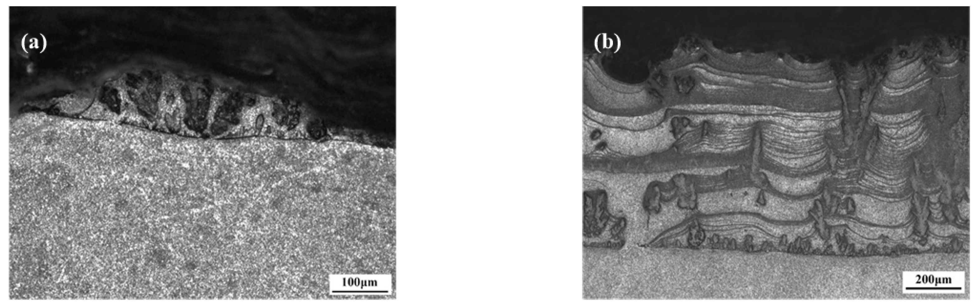
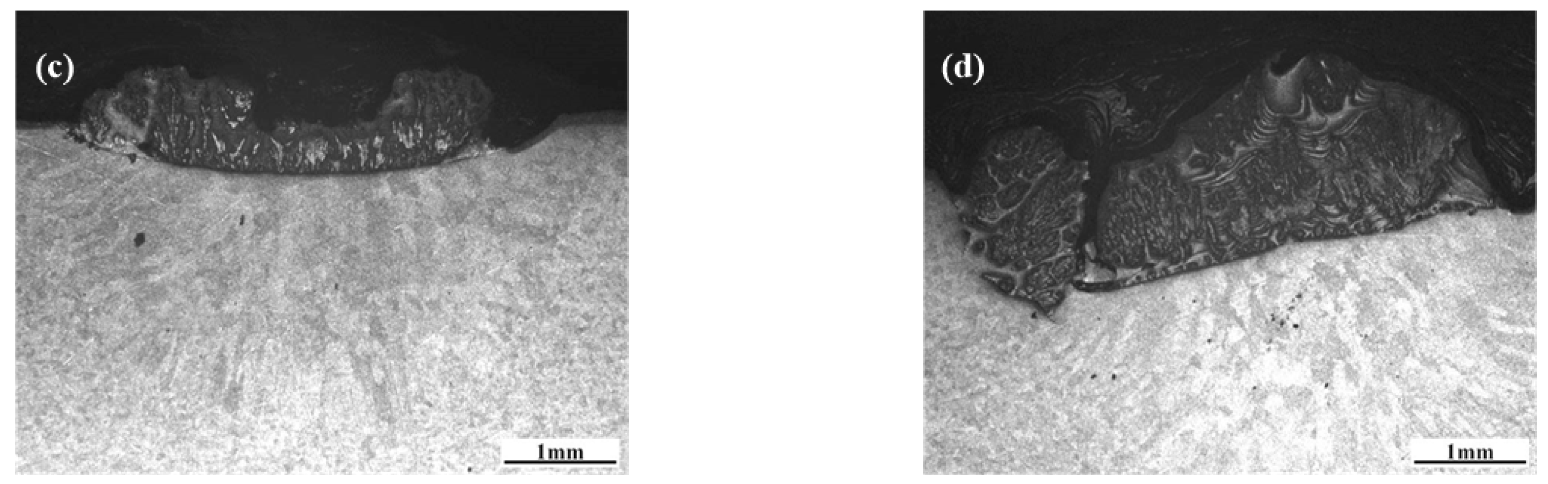
3.1. Microstructural Characteristics of the Nitrided Layer

In this section, AlN-1060 and AlN-6082 prepared by a discharge current of 140 A with an N2 flow rate of 5 L/min were used to analyze the strengthening layer structures on different substrates.

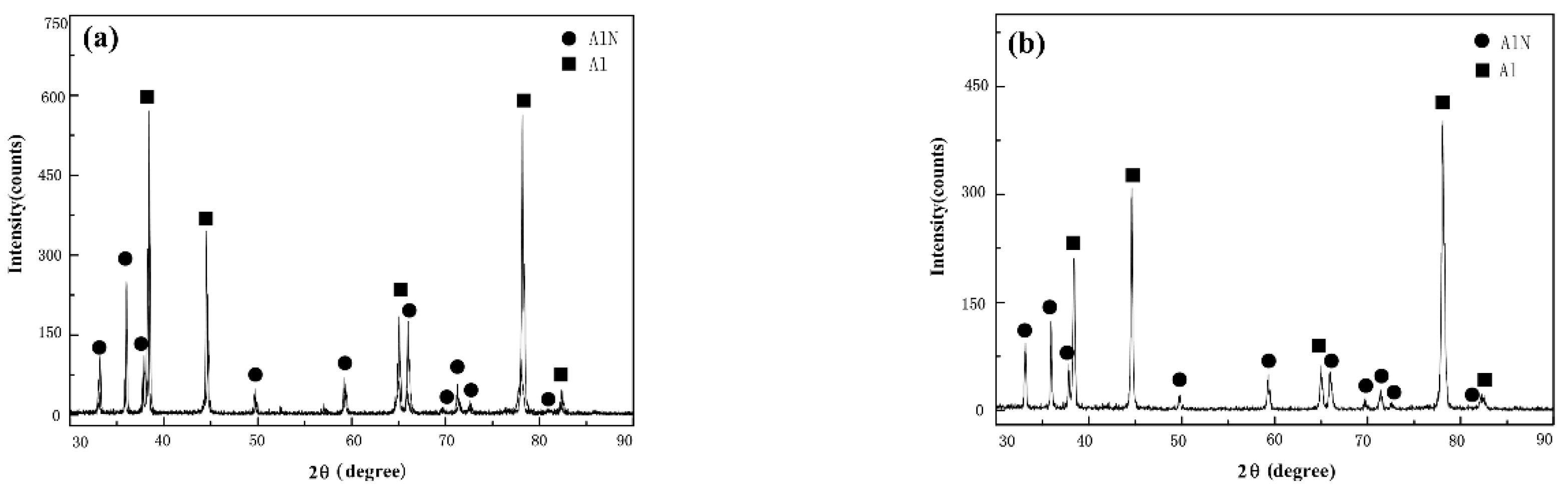
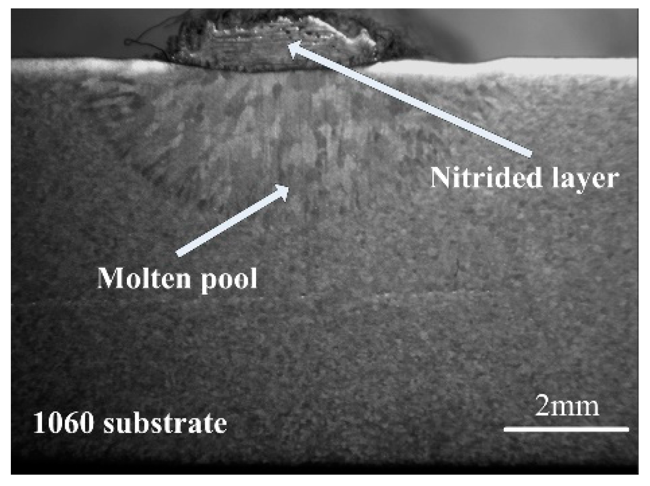
3.1.1. Morphological Characteristics and Phase Compositions of the Nitrided Layer

The surfaces of AlN-6082 and AlN-1060 were analyzed by XRD and the results are shown in Figure 1. As the figures show, these two different layers had very similar diffraction patterns and only two kinds of phases were found: one is hexagonal wurtzite-type AlN (h-AlN, PDF#76-0565) and the other is α-Al (PDF#85-1327).
A typical cross-sectional picture of the nitrided layer is shown in Figure 2. In this picture, the nitrided layer has a rough surface and the layer is significantly higher than the substrate. It is obvious that a molten pool is located below the nitrided layer, whose width is bigger than that of the nitrided layer. The interface between the nitrided layer and the molten pool is quite flat and the molten pool on both sides of the nitrided layer is recessed downward. The average width of the molten pool is about 6 mm.
AlN-6082 and AlN-1060 also had quite similar microstructures. Figure 3 are OM photographs of these nitrided layers. As shown in Figure 3, they were both around 1 mm thick, though AlN-6082 was a little thinner than AlN-1060, and they bulged outward from the surfaces of the substrates. Both of these layers were divided into three regions: the lamella (or lamellar structural) region, the dendrite (or dendritic crystal) region, and the transition region. The lamella region was located in the upper and the middle parts of the layer, with thin black lamellae and thick light-grey lamellae alternatively arraying in it. The dendrite region was below the lamella region with several dendrite-like structures in it. The transition region was located below the dendrite region and looked like a dark line adjacent to the substrates. Among these regions, the lamella region was the dominant one both in scale and the effects on properties. In order to show the structural details of these regions, the enlarged views of their microstructures will be discussed below separately.

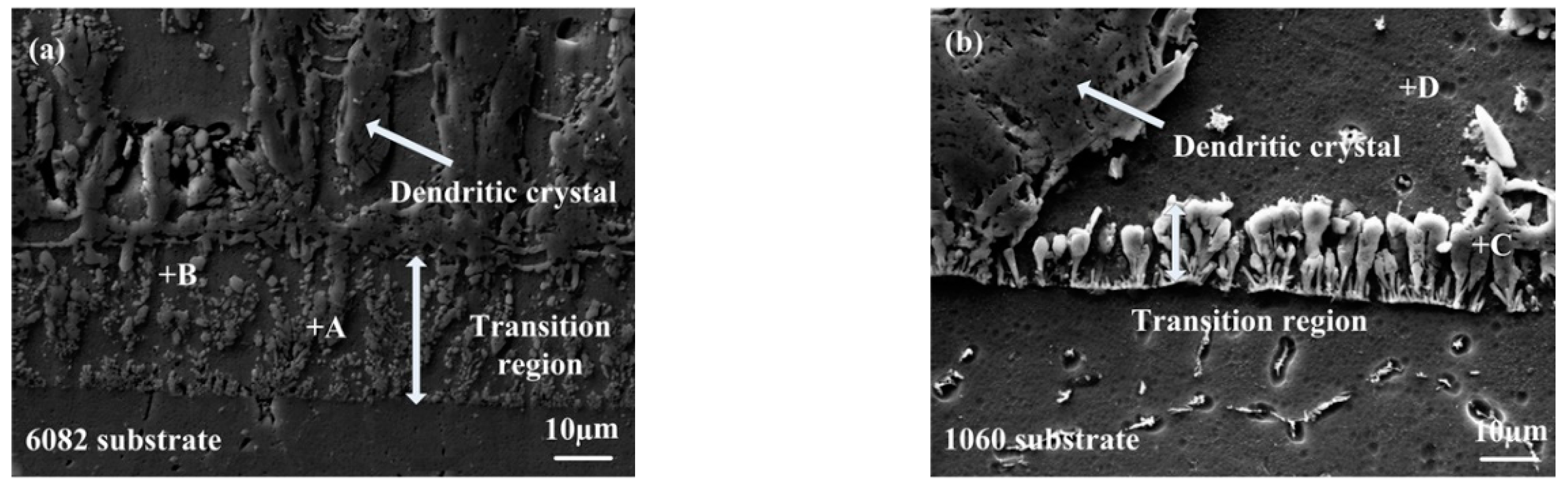
3.1.2. Microstructures of the Transition Region

Microstructures of the transition region in different layers are demonstrated in Figure 4. As the pictures show, the microstructures of this region change as substrates vary. In order to identify different phases, EDS was applied on the spots marked in Figure 4, and the results are shown in Table 1. The phases corresponding to the spots (also shown in Table 1) were recognized according to the ratios of N and Al elements, the XRD results above, and the AlN phase diagram [14]. In these two different layers, the morphologies of AlN changed obviously in the transition region. In that region of AlN-6082, the AlN phase was generated as small particles (spot A) dispersed in Al solid solution (spot B). But in the same region of AlN-1060, the AlN phase was formed as small columnar crystals (spot C) perpendicular to the substrate and surrounded by Al solid solution (spot D). It is worth noting that both of the transition regions on different substrates were constituted by loose and porous structures which Al melt can transfer through.
The structural differences of the transition region are caused by the formation process. As the following text shows (Section 3.2), the transition region is first generated during the nitriding process. Without any AlN crystal existent, the nucleation process becomes very important and time-consuming when this region is emerging. Mg and Si elements in 6082 play important roles as nucleating agent and catalysts in the nitriding reaction [15,16], which contribute to the formation of small and dispersed AlN particles. On the 1060 substrate, without these alloying elements, the AlN crystals will nucleate along the solid-state substrate to reduce the energy. These nuclei then grow into small dendrites due to the lack of nucleus in high nitrogen concentration conditions.

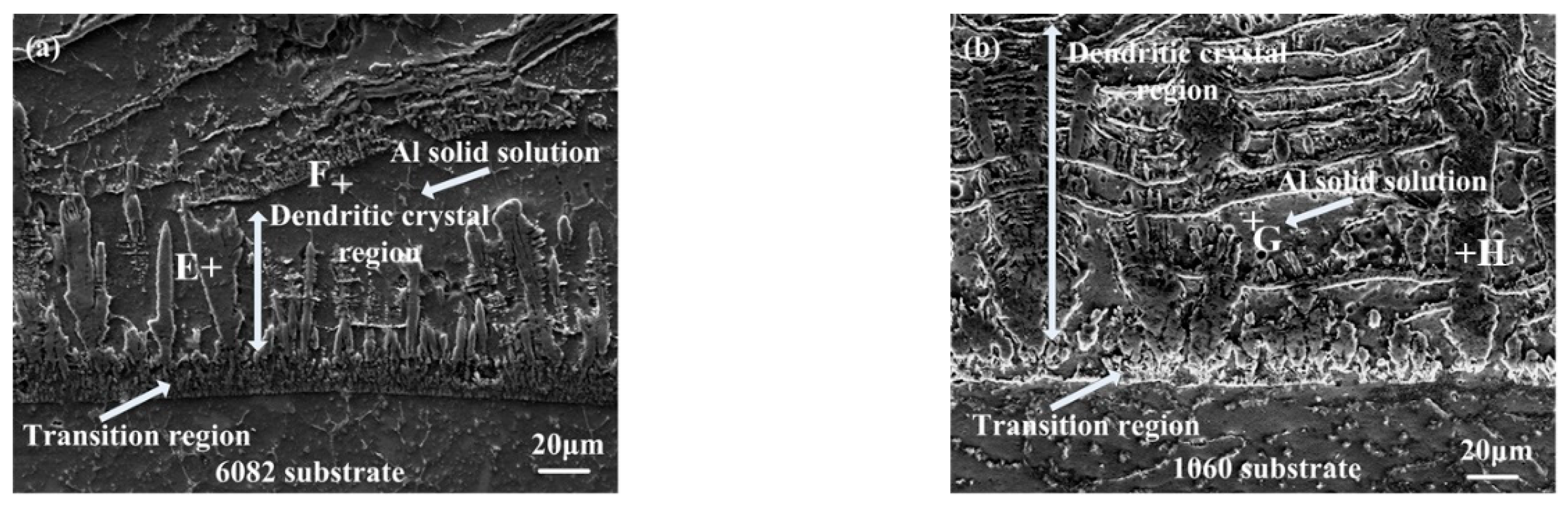
3.1.3. Microstructures of the Dendrite Region

The dendrite region was located above the transition region. The SEM micrographs of the dendrite regions are illustrated in Figure 5. EDS results of the spots marked in the pictures are listed in Table 2. By the same method, dendritic crystals were recognized as an AlN phase and the other phase between them is Al solid solution. As for the scales of the structure, the AlN dendrites on 6082 had a width of 5–8 μm and a height of 34–52 μm, but those on 1060 were much bigger and developed, with widths of 22–30 μm and heights of 56–87 μm.
Morphological differences on various layers in this region are mainly caused by the microstructures of the transition region. On AlN-6082, abundant AlN particles in the transition region act as growth centers when the dendrite region starts to form. Then AlN dendrites grow up together and the nitrogen content in the melt is consumed. As a result, a large number of dendritic crystals are formed in small sizes. In contrast, the number of columnar crystals in AlN-1060 is far less than AlN-6082. That makes the existent columnar crystals grow up without competition. Finally, the dendrites become scarce but in big sizes in AlN-1060.
Microstructures of AlN-1060 also have been analyzed by the TEM method. The TEM micrograph and the selected area electron diffraction (SAED) patterns are shown in Figure 6. Figure 6a shows a horizontal section from the bottom part. In this photo, pebble-shaped particles can be seen clearly, which distribute evenly in the light grey substrate with diameters varying from 200 nm to 500 nm. Figure 6b–d shows the SAED patterns of the spots marked in Figure 6a and the substrate. As the patterns show, the substrate was in the α-Al phase, and both A and B points were an h-AlN phase, only different in orientation. The difference in the brightness contrast of AlN particles was due to the change of orientation in Figure 6a. It also shows that some dislocations existed in the Al phase, which indicates the deformation during the nitriding process.
During the nitriding process, the AlN phase in the nitrided layer is firstly generated and maintains the solid state during the subsequent temperature increase. At the same time, Al melt both in the nitrided layer and in the molten pool is in the liquid phase and moves upward, until the temperature decreases to the solidification point at the end of the nitriding process. Due to the difference in the thermal expansion coefficient between AlN and Al, and the solidification shrinkage of Al melt, stress is generated inside the nitrided layer and dislocations are formed in Al phase.

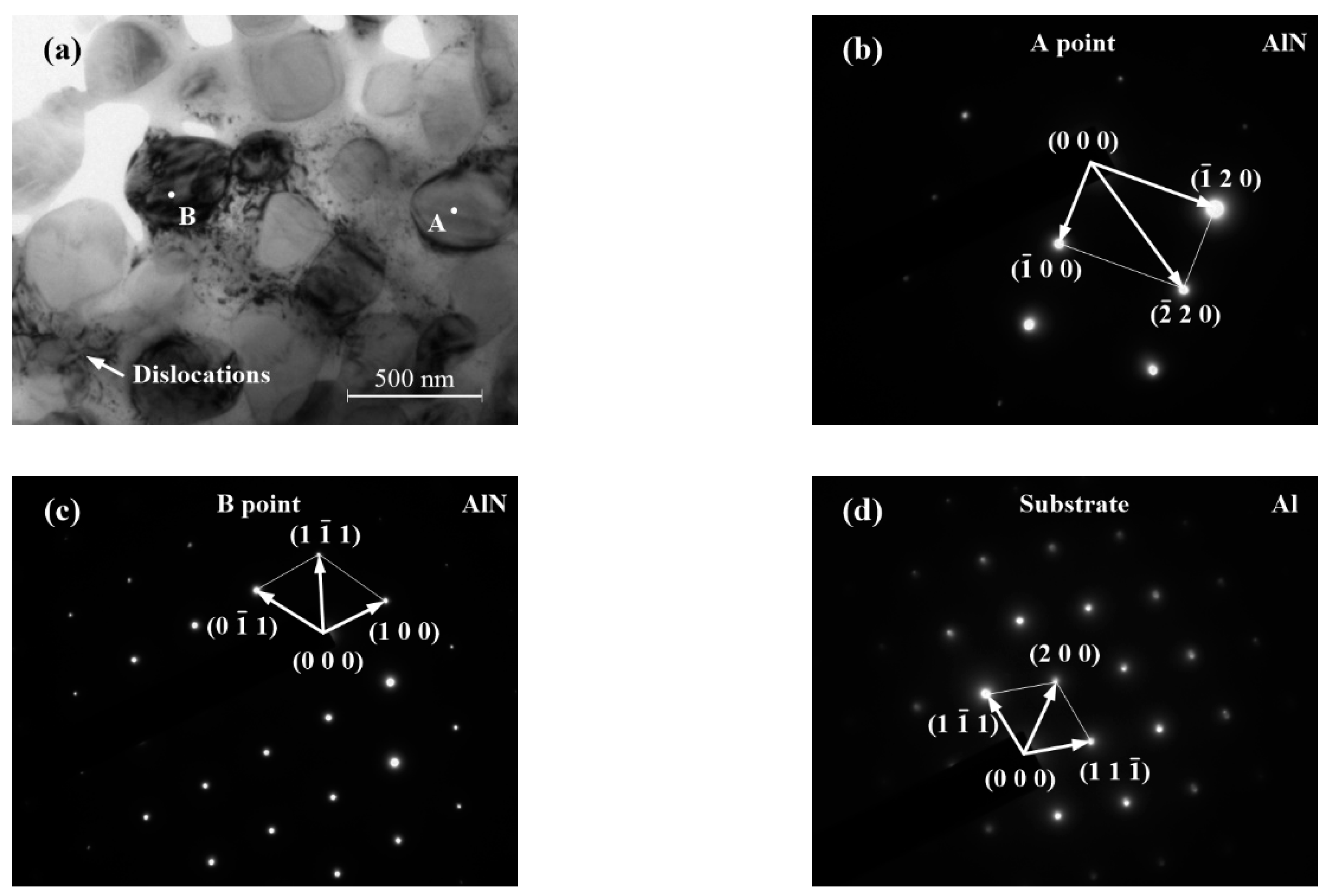
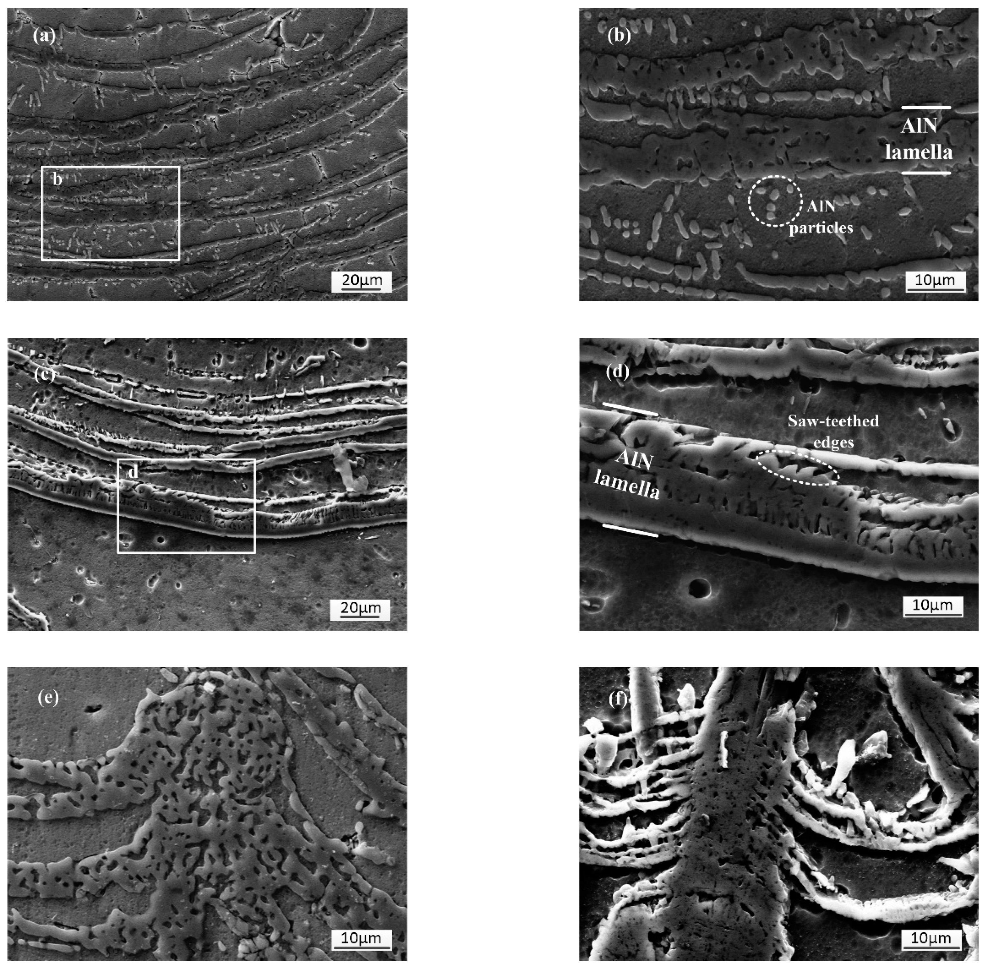
3.1.4. Microstructures of the Lamella Region

The lamella region is the largest region in the nitrided layer, which was located above the dendrite region. The structures of the lamella region in different nitrided layers are shown in Figure 7. As Figure 7a–d show, the lamella structures were arranged repeatedly in this region. According to the analysis, the thin black lamellae were in AlN phase, while the thick light gray substrate was mainly composed of Al solid solution. Meanwhile, AlN phase could also appear as a dendrite-like structures inserted in the lamellae, as Figure 7e,f shows. This structure was always perpendicular to the substrate, with a number of tiny voids in it. Furthermore, the dendrite-like structure was not a single crystal but was heaped up by many tiny lamellae. This structure also could affect the lamellae nearby and bend them upward.
The structure of the AlN lamella had different details in different layers. The lamellae in AlN-6082 were composed of small round or elliptic particles and had smooth edges. Nevertheless, the lamellae in AlN-1060 had some saw teeth on the edges, and even lath-like tissues could be formed on those places.
This phenomenon can also be explained by the formation mechanism. As mentioned above, Mg and Si elements are helpful to the nucleation and growing processes, which leads to a mass quantity of AlN particles generated in AlN-6082. Then, these particles grow up and link together to form a lamella with smooth edges. But in that region of AlN-1060, the nucleation is much harder to start, so a more oversaturated N condition is needed. Firstly, a tiny layer of nuclei is formed by homogeneous nucleation. Then, these nuclei extend in polygon shapes. Finally, these tiny polygon crystals link together and a lamella is formed with saw-toothed structures or lath-like tissues on the margin. In addition, there are some pretty small AlN phases between lamellae: round particles in AlN-6082, and polygon dendrites in AlN-1060.

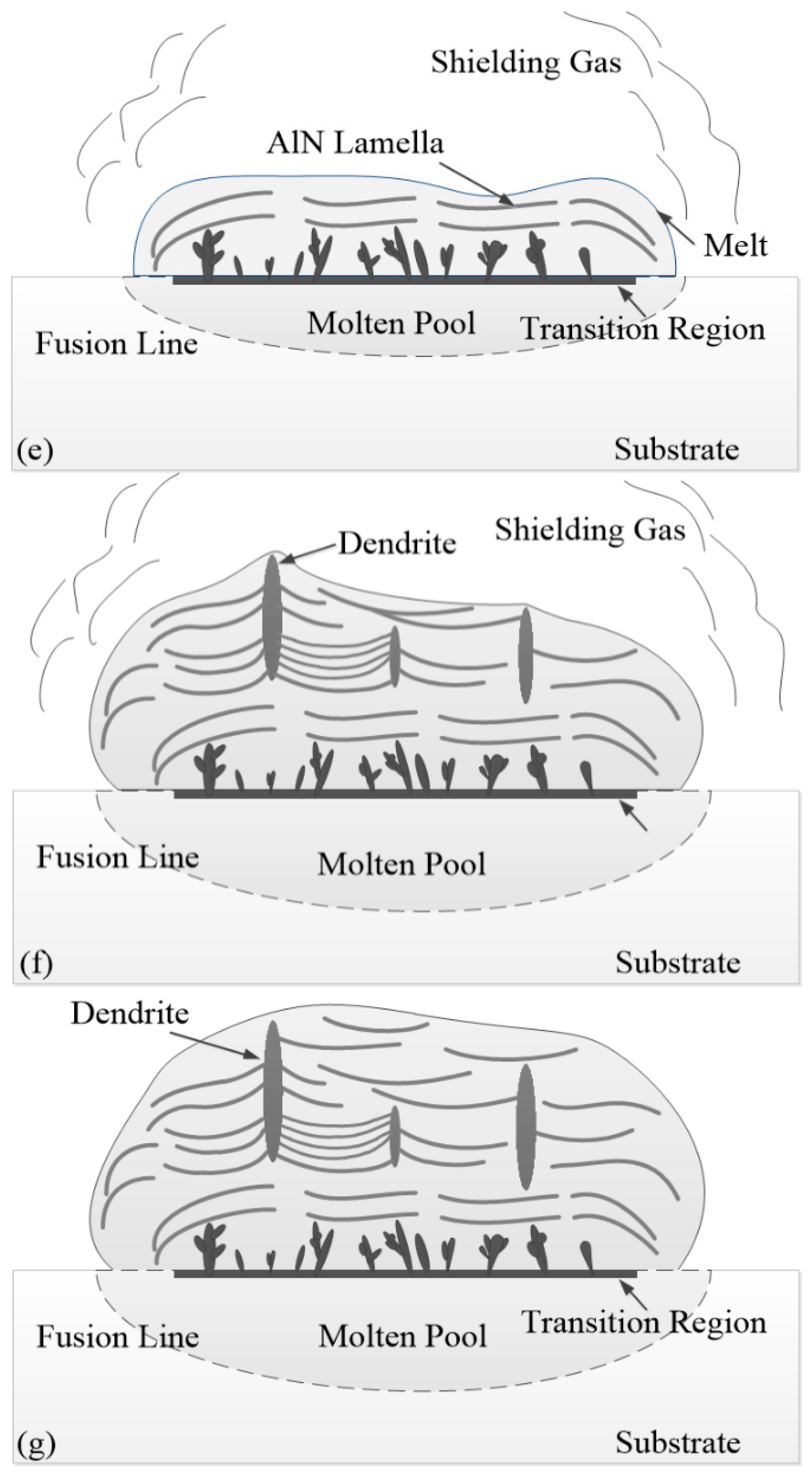
3.2. Formation Mechanisms and Processes of the Nitrided Layer

During the whole nitriding process, a large number of thermal plasma species, such as Ar+, N2+, N+, and N atoms, are generated and bombard the melt surface. Among these particles, N+, N2+, and N can react with Al melt to form AlN. The total reaction can be described as
Al + N+ (N2+,N) → AlN,
To investigate the formation process of the nitrided layer, a special sample was prepared by a discharge current of 110 A with N2 flow rate of 2.5 L/min. After nitriding, the sample was quenched into water immediately and cut from the end of the nitrided layer against the travel direction. The OM pictures of this section are illustrated in Figure 8.
Figure 8a shows the entire evolution of the AlN strengthening layer. From right to left in this picture, three regions of the AlN structures described in Section 3.1 can be found easily. Figure 8b,c are the enlarged pictures of the right parts in Figure 8a. At the right part of Figure 8b, the transition region is formed on the substrate with several tiny dendrites in it. At the left part of the picture, the tiny dendrites grow up to form the dendrite region. In Figure 8c, the lamella region is formed above the dendrite region and the dendrite-like structures start to be formed. Three regions are distributed at different but constant heights in Figure 8a, which indicates that as the nitriding process goes on, Al melt transfers upward through the pre-formed AlN structures, submerges them, and then reacts with the nitride plasma above [17,18,19].
According to the structures shown in Figure 8, a brief nitriding process is demonstrated. At the beginning of the nitriding process, the temperature is low and only the surface of the substrate melts. This extremely thin melt layer interacts with the nitrogen arc to form the transition region [19]. As the nitriding process goes on, the temperature rises up, the molten pool extends downward, but, hindered by the transition region, N diffusion to this area is not obvious. The melt from the molten pool moves upward through the transition region to the top of the nitrided layer and reacts with the nitrogen plasma. The formed AlN phase maintains a solid state during the whole nitriding process. So, the AlN structure works like the skeleton supporting the whole nitrided layer and generates many small channels where Al melt transfers through. At the final stage of the nitriding process, the temperature drops to the Al melting point, and Al melt in the nitrided layer starts to solidify. In addition, in the molten pool under the nidrided layer, the voids generated by the upward transport of the melt are filled by the melt from the periphery of the molten pool, causing the nitrided layer to be higher than the surface of the substrate, and the molten pool on both sides of the nitrided layer to recess downward. The detailed analysis is also demonstrated below.
As Al melt moves upward, different regions are formed in sequence during the nitriding process. This formation process of the nitrided layer is portrayed in Figure 9. The locations of each stage are marked in Figure 9a. As Figure 9a shows, the nitriding reaction mainly occurs in the first half of the thermal cycle, where the temperature is on the rise, and the nitrided layer is basically formed under the center of the arc. As mentioned above, at the beginning of the nitriding process, the transition region is first generated. As Section 3.1.2 portrayed, when this region is formed, nucleation happens, which is a time-consuming process. This process only consumes very little N element, so the melt still has a great N supersaturation. The formation of the transition region is shown in Figure 9b,c.
As the nitriding process goes on and the temperature increases, the molten pool extends downward. Al melt has a very low dynamic viscosity. If the density of Al melt has been taken into account, the kinetic viscosity of the aluminum melt is lower than that of water. Therefore, Al melt can transfer from the molten pool to the surface of the nitrided layer through the poriferous transition region. Meanwhile, the wettability of the AlN phase in Al melt is pretty good, so Al melt can easily submerge the transition region. In this step, Al melt from the molten pool has a high N concentration and then the concentration is increased by the plasma bombardment. That leads to the surface of the nitrided layer having a very great N supersaturation. Under this condition, some AlN grains on the edge of the transition region grow up rapidly to form the dendrite region. As dendrites grow, the melt transfers upward simultaneously (Figure 9d).
These dendrites grow very fast and facilitate the transport of Al melt. The dendrites grow faster than the transport of Al melt and push the superficial melt outward. The surface of the melt is affected by the inward surface tension and the dendritic outward thrust, which leads to the surface swelling out. Meanwhile, Al melt is pushed upward by atmospheric pressure and the melt transport is increased.
The transport of Al melt can be proved by calculation. Between neighboring dendrites, a capillary void can be formed where the capillary stress is generated. This stress can be calculated by Laplace’s law:
Δp = 2γ/r,
Δp is the additional pressure, γ is the surface tension of Al melt, which is 1.1 J/m2 [20], and r is the curvature radius of the melt surface, which can be estimated by the curvature radius of lamellae. In the lamella region, the curvature radiuses of different lamellae are measured. The r values of the lamellae near the dendrite-like structure in Figure 7e and Figure 7f were 73.5 μm and 31 μm respectively, and the additional pressures were calculated as 3.0 × 10⁴ Pa and 7.1 × 10⁴ Pa. These tremendous pressures are strong enough to lift the melt upward in the capillary voids. Furthermore, in the dendrite region, the dendrites are much closer and the r values are smaller, which indicates the pressure will be much higher. Because of the large number of capillaries distributed in the dendrite region and the great kinematic viscosity of Al melt, a great amount of Al melt can be transported upward in a considerable velocity.
As the melt moves upward, the N concentration is reduced by the rapid growth of the dendrites. However, the rapid growth of the dendrites requires a large N concentration in the melt near the tips of the dendrites. As a consequence, the N concentration in the melt cannot satisfy the strong need of dendrites, which leads to the stop of the dendrite growth. Due to the low N concentration of the superficial melt, it cannot form any AlN structures in this moment.
With the movement of the arc, the temperature increases. The surface of the melt is bombarded by the nitrogen plasma, which increases the N concentration of the superficial melt. Once the N concentration exceeds the thermodynamic reaction condition, an AlN lamella structure will be formed on the surface of the melt. The formed lamella has a very loose structure with many cracks and voids, where the melt can transfer. The N concentration of the melt is reduced by the formation of the AlN phase. When the melt submerges this newly born lamella, N concentration cannot meet the needs of the growth of the AlN structure, so a layer of Al melt is left on the layer surface and then the formation of the AlN lamella will repeat. Through the change of N concentration in the melt, the AlN lamella and Al melt layer are repeatedly generated (Figure 9e).
During the nitriding process, most of the lamellae formed in the lamella region have a concave shape, which is caused by the arc blow force. The ends of lamellae curl up to a higher location, from which the distance to the melt surface is shortened. With the bombardment of N plasma, the N concentration of the melt near the ends of the lamellae is higher than other areas, which facilitates the further growth of the pre-formed AlN structures. At some positions of these ends of the lamellae, the dendrite-like structures are formed (Figure 9f).
For the formed dendrite-like structures often located at a higher position in the melt, the melt around the tips of these dendrite-like structures always has a higher N concentration. Under this condition, the growth of the dendrite-like structures is very rapid and pushes the superficial melt outward, which facilitates the transport of Al melt. However, when the dendrite-like structures grow faster than the transport of Al melt, the melt replenishment will be difficult. Finally, the tips of the dendrite-like structures will extend outside the melt and be exposed to gas. At this time, the growth of the dendrite-like structures stops. When the melt covers the dendrite-like structure again as the whole melt moves up, this dendrite-like structure will be submerged deeper. The N concentration in the melt nearby will be too low to meet the needs of the growth of the dendrite-like structure. The AlN phase will return to the lamella shape. These two different shapes are generated alternately in the lamella region until the nitriding process is complete (Figure 9g).

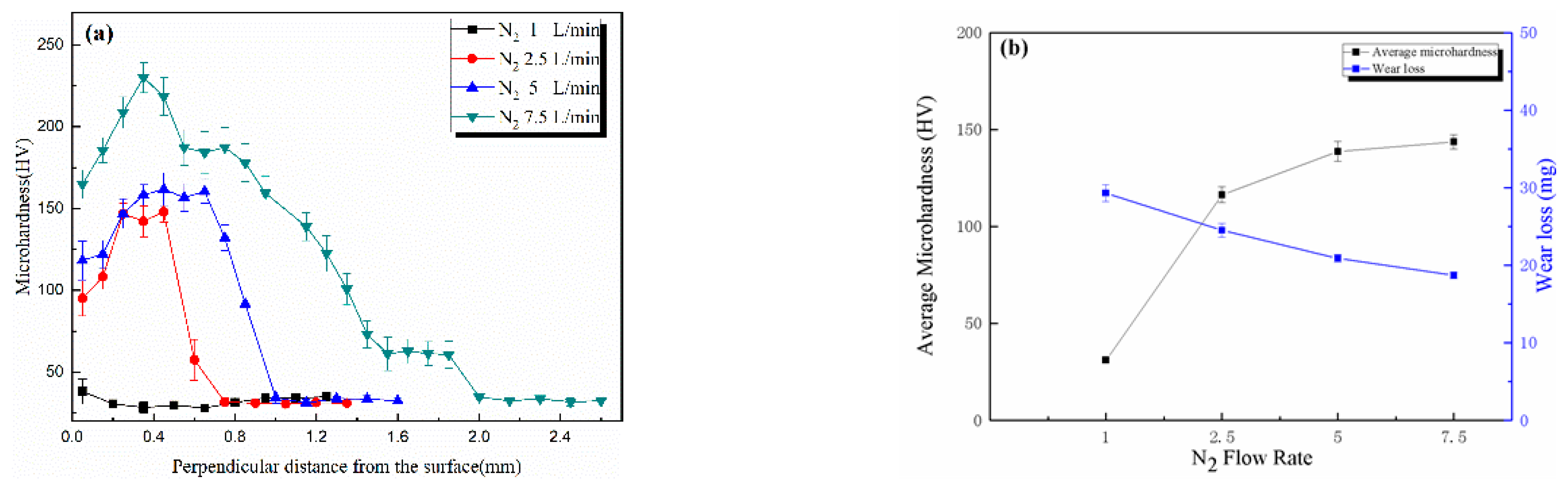
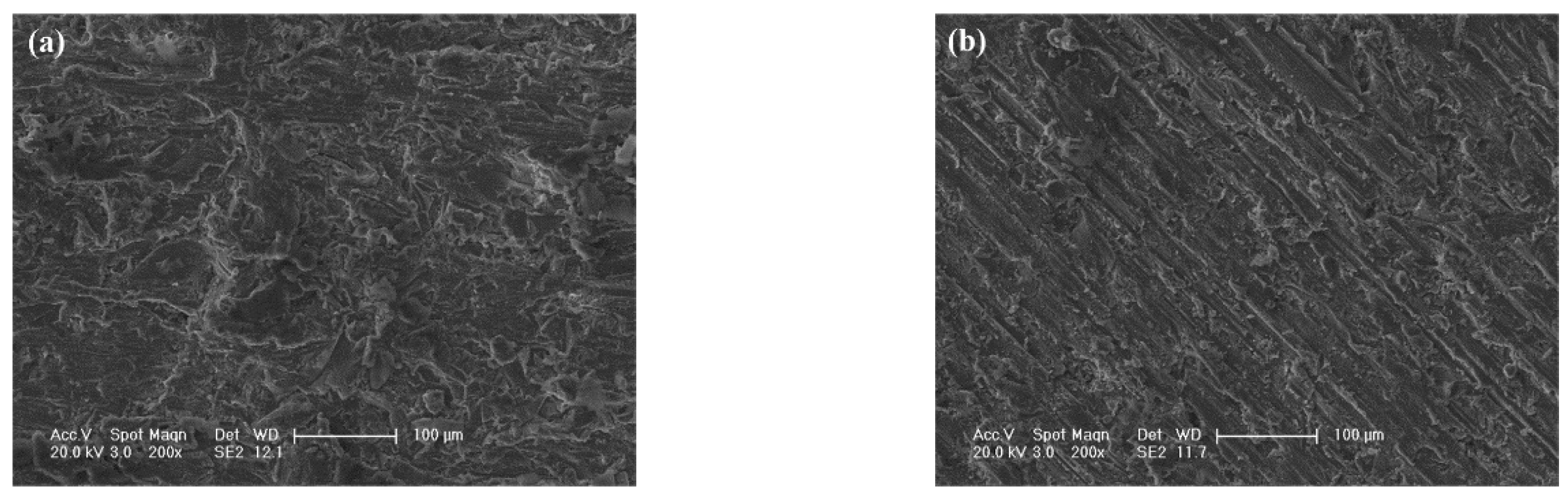
3.3. Effects of N2 Flow Rate upon Nitrided Layers on 6082 Substrates

Figure 10 shows the structures of AlN-6082 prepared by a discharge current of 110 A under different N2 flow rates. In these pictures, the layers have the same basal structures, including the transition region at the bottom, the dendrite region in the middle, and the lamella region on the top, but their scales and distributions are different.
As the pictures show, with the increase of N2 flow rates from 1 L/min to 7.5 L/min, the scale of the nitrided layer is enhanced in thickness, from 100 µm to 1500 µm. The width of the molten pool also increases with the increase of N2 flow rates. The widths of the molten pool corresponding to Figure 9a–d were 3 mm, 4 mm, 5 mm, and 6 mm respectively. As N2 flow rate increases to 5 L/min, the whole nitrided layer will be too heavy to keep its initial shape and start to bend and sink into the molten pool.
Compared with AlN-6082 prepared by a discharge current of 140 A, AlN-6082 prepared by a discharge current of 110 A has more considerable dendrite-like structures distributed from the bottom to the top. That is because the lower discharge current decreases the transport speed of the melt, which facilitate the formation of the dendrite-like structures. In addition, with the increase of N2 flow rates, the dendrite-like structures grow more developed. The lamellae between adjacent dendrite-like structures are impacted closely. These developed dendrite-like structures and closely packed lamellae can increase the percentage of AlN phase, and improve the mechanical properties of the nitrided layer.
The hardness characters and the wear losses of the nitrided layers are shown in Figure 11. Figure 11a demonstrates the microhardness curves of different layers. The strengthening layer is composed of the AlN phase and Al phase, so the hardness of the layer is determined by the distributions and characters of both phases, especially the ratios of the AlN phase to the total material. When N2 flow rate is 1 L/min, the enhancement is not obvious due to the poor thickness of the nitrided layer. With the increase of N2 flow rate, the average hardness of the layer is improved. When the N2 flow rate is 7.5 L/min, the average hardness is nearly 7 times as that of the substrate. Excluding the curve of N2 flow rate 1 L/min, these hardness curves bend upward in the middle, which means that the hardness increases firstly to a maximum, and then drops down. This phenomenon is caused by the distribution of the AlN phase: during the formation of the bottom and the top parts, the melt layer is farther away from the arc center, which leads to the shortage of N element (compared to the middle part which is formed just under the center of the ionized gas), which causes a scarcity of AlN in these parts. By analyzing hardness curves and the structures of the layers, it was found that the dendrite-like AlN structure in the lamella region had the main influence on improving the average hardness. So, a bigger N2 flow rate should be used to get a harder nitrided layer.
Figure 11b shows the average hardness and wear loss of different layers. All the microhardness values in the nitrided layers are summed together then divided by the number of points to calculate the average hardness values. According to this picture, the wear resistance property has a consistent change with the average microhardness. When N2 flow rate is increased, wear loss will be reduced with the increase of the average microhardness. At 7.5 L/min, the wear loss is only 18.7 mg, which is only half of the 6082 substrate (38.7 mg). The micrographs of the worn surfaces under various N2 flow rate conditions are also demonstrated in Figure 12. When N2 flow rate is only 1 L/min, wear loss is mainly caused by adhesive wear mechanism as shown in Figure 12a. Nevertheless, as N2 flow rate is added to 5 L/min, the furrows become obvious and plastic flow is diminished in Figure 12b, which suggests the mechanism changes from adhesive wear to abrasive wear.

4. Conclusions

(1) By thermal plasma nitriding method, the AlN strengthening layer can be prepared on 1060 and 6082 substrates. These strengthening layers are mainly composed of Al and AlN phases. Both of AlN-1060 and AlN-6082 can be divided into three regions: the transition region, the dendrite region, and the lamella region.
(2) The formation mechanism of the nitrided layer is proposed according to the microstructure characteristics of the layer. During the nitriding process, Al melt transports from the molten pool to the melt surface through the voids and the capillaries in the AlN structures, and reacts with N plasma to form the AlN phase. The growth of the AlN structures promotes the transport of Al melt by pushing the melt surface outward. Finally, the transition region, the dendrite region, and the lamella region are sequentially formed.
(3) As the N2 flow rate increases from 1 L/min to 7.5 L/min in the ionization gas, the hardness and the wear resistance of the nitrided layer are both improved, and the thickness of the nitrided layer is also increased. When the N2 flow rate is 7.5 L/min, the average hardness of the nitrided layer is nearly 7 times that of the substrate, the wear resistance is increased to 2 times that of the substrate, and the thickness of the layer is 1.5 mm.

Author Contributions

Conceptualization, X.L.; formal analysis, W.X.; methodology Z.R.; investigation, W.L. and X.Z.; supervision and validation, D.S.; writing—original draft, W.X.; writing—review and editing, X.L.

Funding

This work is financially supported by the National Natural Science Foundation of China (No. 51101072), the Science and Technology Development Project of Jilin Province (No. 20150520024JH) and the Co-construction Project between Jilin Province and Jilin University (No. 440050316A14).

Conflicts of Interest

The authors declare no conflict of interest.

References

  1. Jagielski, J.; Piatkowska, A.; Aubert, P.; Legrand-Buscema, C.; Le Paven, C.; Gawlik, G.; Piekoszewski, J.; Werner, Z. Effects of high dose nitrogen implantation into aluminum. Vacuum 2003, 70, 147–152. [Google Scholar] [CrossRef]
  2. Bashir, M.I.; Shafiq, M.; Naeem, M.; Zaka-ul-Islam, M.; Díaz-Guillén, J.C.; Lopez-Badillo, C.M.; Zakaullah, M. Enhanced surface properties of aluminum by PVD-TiN coating combined with cathodic cage plasma nitriding. Surf. Coat. Technol. 2017, 327, 59–65. [Google Scholar] [CrossRef]
  3. Huashun, Y.; Kim, J.D.; Kang, S.B. The formation of AlN and TiN particles during nitrogen bearing gas injection into Al-Mg-Ti melt. Mater. Sci. Eng. A 2004, 386, 318–325. [Google Scholar] [CrossRef]
  4. Abreu, C.M.; Cristóbal, M.J.; Figueroa, R.; Pena, G. Wear and corrosion performance of two different tempers (T6 and T73) of AA7075 aluminium alloy after nitrogen implantation. Appl. Surf. Sci. 2015, 327, 51–61. [Google Scholar] [CrossRef]
  5. Czerwiec, T.; Michel, H.; Bergmann, E. Low-pressure-high density plasma nitriding: Mechanisms, technology and results. Surf. Coat. Technol. 1998, 108–109, 182–190. [Google Scholar] [CrossRef]
  6. Minto, T.A.; De Oliveira, V.M.C.A.; Voorwald, H.J.C. Plasma immersion ion implantation: Influence on the rotating bending fatigue strength of AA 7050-T7451 aluminum alloy. Int. J. Fatigue 2017, 103, 17–27. [Google Scholar] [CrossRef]
  7. Ebisawa, T.; Saikudo, R. Formation of aluminum nitride on aluminum surfaces by ECR nitrogen plasmas. Surf. Coat. Technol. 1996, 86–87, 622–627. [Google Scholar] [CrossRef]
  8. Thibault, S.; Hug, E. Corrosion and wear mechanisms of aluminum alloys surface reinforced by multicharged N-implantation. Appl. Surf. Sci. 2014, 310, 311–316. [Google Scholar] [CrossRef]
  9. Manova, D.; Mändl, S.; Rauschenbach, B. Evolution of surface morphology during ion nitriding of aluminium. Surf. Coat. Technol. 2004, 180–181, 118–121. [Google Scholar] [CrossRef]
  10. Tran, A.T.; Pandraud, G.; Schellevis, H.; Sarro, P.M. Enhancement of AlN slender piezoelectric cantilevers actuation by PECVD Silicon Nitride coating. Procedia Eng. 2012, 47, 104–107. [Google Scholar] [CrossRef]
  11. Figueroa, U.; Salas, O.; Oseguera, J. Production of AlN films ion nitriding versus PVD coating. Thin Solid Film. 2004, 469–470, 295–303. [Google Scholar] [CrossRef]
  12. Renevier, N.; Czerwiec, T.; Billard, A.; Von Stebut, J.; Michel, H. A way to decrease the nitriding temperature of aluminium the low-pressure arc-assisted nitriding process. Surf. Coat. Technol. 1999, 116–119, 380–385. [Google Scholar] [CrossRef]
  13. Möller, W.; Parascandola, S.; Telbizova, T.; Günzel, R.; Richter, E. Surface processes and diffusion mechanisms of ion nitriding of stainless steel and aluminum. Surf. Coat. Technol. 2001, 136, 73–79. [Google Scholar] [CrossRef]
  14. Siang-Chung, L. Phase stability of the Al–N system. J. Mater. Sci. Lett. 1997, 16, 759–760. [Google Scholar] [CrossRef]
  15. LeHuy, H.; Dallarie, S. Effects of Si and Mg dopants on the kinetics of aluminum alloys nitridation. Proc. Ceram. Met. Matrix Compos. 1989, 302–311. [Google Scholar] [CrossRef]
  16. Jin, H.B.; Chen, K.X.; Zhou, H.P.; Wang, Y.D.; Zou, Z.S.; Wang, W.W. Synthesis of aluminum nitride powder by in situ reaction. Acta Metall. Sin. (China) 2000, 36, 775–779. [Google Scholar]
  17. Newkirk, M.S.; Urquhart, A.W.; Zwicker, H.R.; Breval, E. Formation of Lanxide TM ceramic composite materials. J. Mater. Res. 1986, 1, 81–89. [Google Scholar] [CrossRef]
  18. Antolin, S.; Nagelberg, A.S.; Creber, D.K. Formation of Al2O3/Metal Composites by the Directed Oxidation of Molten Aluminum—Magnesium—Silicon Alloys: Part I, Microstructural Development. J. Am. Ceram. Soc. 1992, 75, 447–454. [Google Scholar] [CrossRef]
  19. Kagawa, Y.; Khatri, S.C.; Koczak, M.J. Directed nitridation of liquid aluminum alloy: Growth process and modeling. In Proceedings of the 17th Annual Conference on Composites and Advanced Ceramic Materials: Ceramic Engineering and Science Proceedings, Hoboken, NJ, USA, 1 January 1993; pp. 776–785. [Google Scholar]
  20. Cao, J.H.; Liu, Y.; Ning, X.S. Influence of AlN(0001) Surface Reconstructions on the Wettability of an Al/AlN System: A First-Principle Study. Materials 2018, 11, 775. [Google Scholar] [CrossRef] [PubMed]
Figure 1. X-ray diffraction patterns of (a) AlN-6082 and (b) AlN-1060.
Metals 09 00523 g001
Figure 2. A typical cross-sectional picture of the nitrided layer.
Metals 09 00523 g002
Figure 3. Optical microscopy (OM) photographs of perpendicular sections from (a) AlN-6082 and (b) AlN-1060.
Metals 09 00523 g003
Figure 4. SEM micrographs of the transition regions on (a) AlN-6082 and (b) AlN-1060.
Metals 09 00523 g004
Figure 5. SEM micrographs of the dendrite regions in (a) AlN-6082 and (b) AlN-1060.
Metals 09 00523 g005
Figure 6. (a) TEM micrograph of the bottom part of AlN-1060. (b) Selected area electron diffraction (SAED) pattern of A point. (c) SAED pattern of B point. (d) SAED pattern of the substrate.
Metals 09 00523 g006
Figure 7. SEM micrographs of the lamella regions. (a) AlN-6082. (b) Increased magnification micrograph in (a). (c) AlN-1060. (d) Increased magnification micrograph in (c). (e) A dendrite-like structure inserting in the lamellae on AlN-6082. (f) A dendrite-like structure on AlN-1060.
Metals 09 00523 g007
Figure 8. To investigate the formation process, the nitrided layer was cut from its end perpendicularly. (a) The entire evolution of the nitride structure. (b) Increased magnification picture of b area. (c) Increased magnification picture of c area.
Metals 09 00523 g008
Figure 9. Formation stages of the nitrided layer. (a) The locations of each stage. (b) The formation of the transition region. (c) The partial enlargement of (a) on different substrates. (d) The formation of the dendrite region. (e) The formation of lamellae in the lamella region. (f) The transformation between lamellae and dendrite-like structures in the lamella region. (g) The final structure of the nitrided layer.
Metals 09 00523 g009aMetals 09 00523 g009b
Figure 10. The macrostructures of nitrided layers prepared under N2 flow rates of (a) 1 L/min, (b) 2.5 L/min, (c) 5 L/min, and (d) 7.5 L/min.
Metals 09 00523 g010aMetals 09 00523 g010b
Figure 11. (a) Microhardness distribution curves of different layers with standard error bars. (b) Average hardness and wear loss of different layers.
Metals 09 00523 g011
Figure 12. SEM pictures of worn surfaces of (a) N2 flow rate of 1 L/min and (b) N2 flow rate of 5 L/min.
Metals 09 00523 g012
Table 1. Energy-dispersive spectroscopy (EDS) results of the spots in Figure 4 (at. %).
ElementABCD
N45.5-50.8-
Al53.698.849.2100
Mg0.50.5--
Si0.40.7--
PhaseAlNAlAlNAl
Table 2. EDS results of the spots on Figure 5 (at. %).
ElementEFGH
N59.7-49.8-
Al48.899.050.2100
Mg-0.5--
Si0.50.5--
PhaseAlNAlAlNAl

