Abstract
The first part of this paper explored the identification of various methodological challenges which have to be addressed when designing complex multi-system integration associated with titanium metalworking and manufacture, while in this second part of the paper, we explore the evolution of System of Systems (SoS) design and development of complex multi-system integration. Theory of Inventive Problem Solving (TRIZ) is employed to address identified system incongruity. The utilization of the SoS design approach coupled with the TRIZ innovation technique proved effective at addressing the system constraints for the titanium manufacturing supply chain. The utilization of the two-part process prescribed by the SoS design approach proved effective at addressing requirements and broadly stated industry needs. Through this unique system, design net-shaped structural beam from common aerospace grade titanium (Ti-6Al-4V) was successfully manufactured.
1. Introduction
With the development of high-level technical objectives for the SoS, development of key interfaces to performance and current performance benchmark set, the architecture of the SoS can be developed further. The defined architecture will form the technical framework for change in the SoS [1]. Taking all previous activities into account, shown in Table 1, the design requirements are reconsidered to address SoS deficiencies in performance. The outcome should also influence the architecture or interconnection of the systems to influence improvement within the system of systems.

Table 1.
System Engineering (SE) technical process as they apply to core SE elements [1].
One of the main objectives of this research is to yield a component closer to a final form for a shape of some level of complexity while having a positive impact on surface quality through roll reductions.
Primary Interfaces
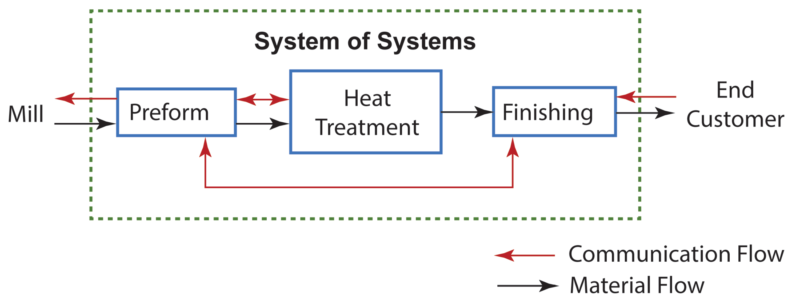
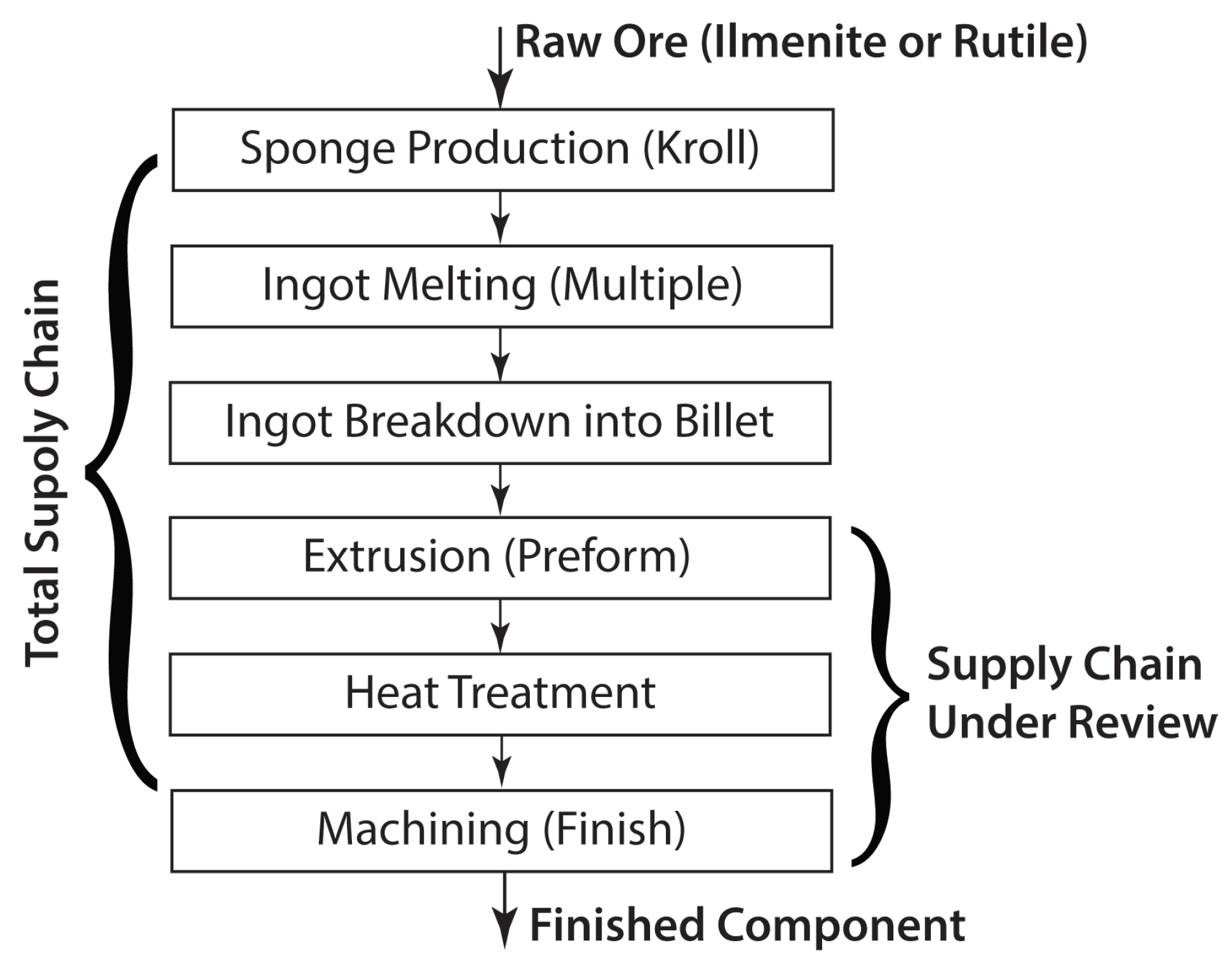
The predominant architecture of the system of systems is subdivided into two categories: pre-form generation and finishing of the pre-form. A hypothetical example of preform and finishing could be forging and subsequent machining to final condition. There are multiple steps typically involved with the pre-form generation. This includes, but is not limited to, heat treating, to align the properties of the material before finishing. Communication flow also does not typically flow linearly through the SoS, as very little interface exists between finishing and heat treatment systems. Without some oversight, communication between these steps may not exist at all, as illustrated in Figure 1.
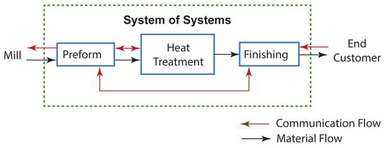
Figure 1.
Flow of information and material through a traditional supply chain for titanium components.
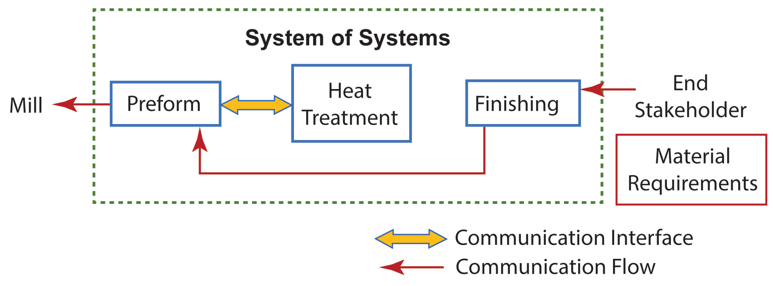
There are two main requirement categories that dictate SoS interaction and involvement: material requirements and conditional requirements. These requirements have a direct impact on the communication that occurs within the SoS.
Material requirements drive a direct interface between preform and heat treatment to ensure that the planned thermo-mechanical history of production steps, will meet requirements placed upon the SoS. The finishing process has very little involvement in this aspect and typically is passing this down from the customer unaltered, as long as the supplied state is compatible with the selected finishing process. There is communication outside of the SoS to the mill. However, this is also typically an information hand off, without an interface. This information usually consists of the condition and chemistry of the primary material desired for SoS input. Figure 2 shows the current flow of information and the existence of collaborative interfaces for this type of SoS.
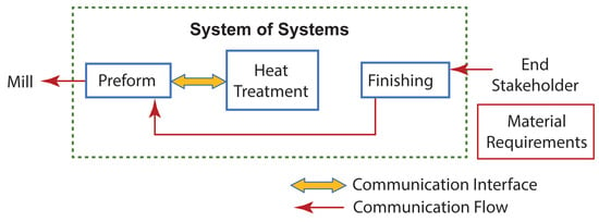
Figure 2.
Flow of information and active interfacing involved with material requirements.
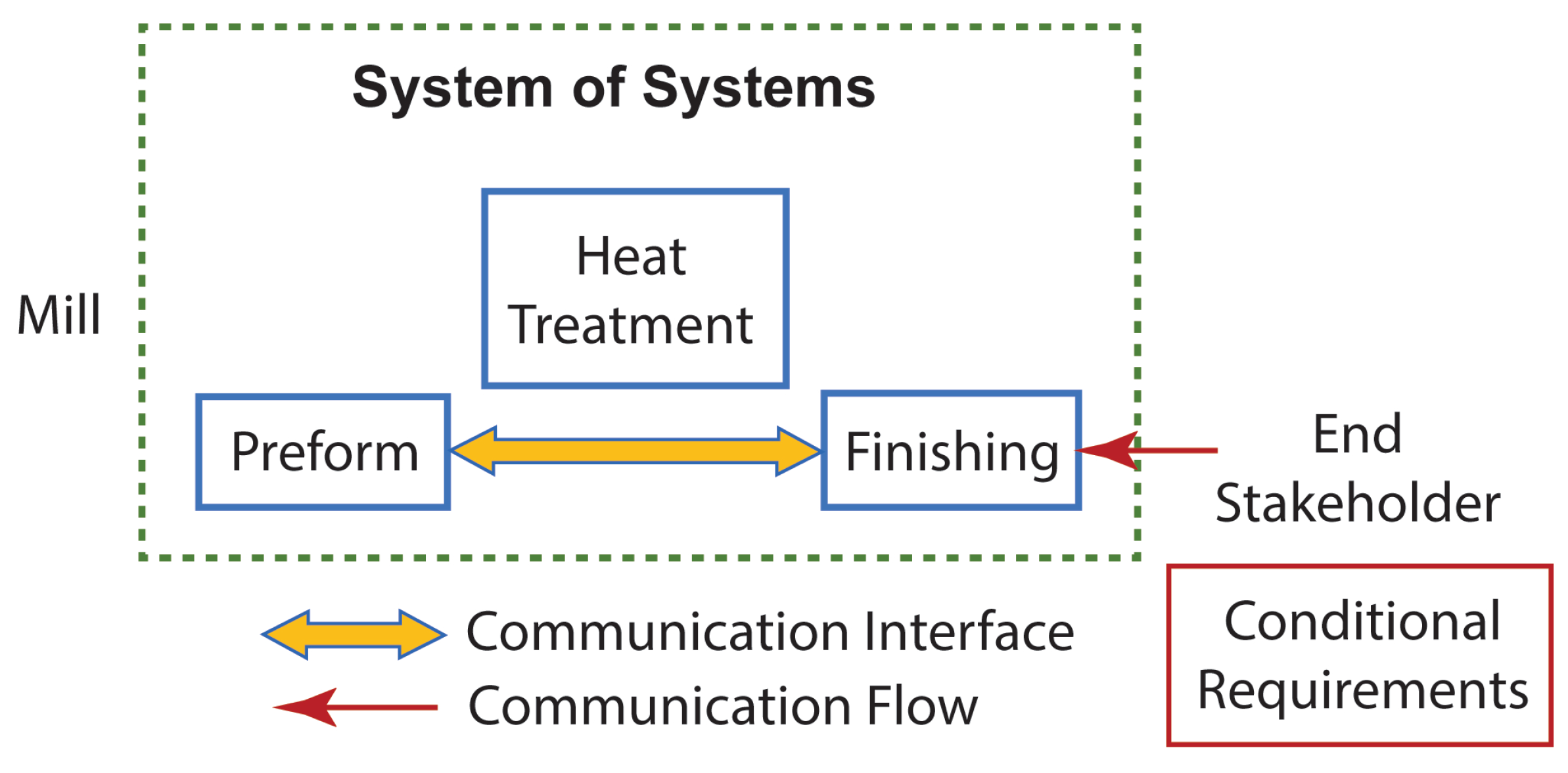
The conditional requirements drive the other predominant interface of the SoS. For this case, the desired conditions of the finished component enter the SoS from the end user or stakeholder. This typically triggers a collaborative design process to align the pre-form output to the finishing input in an efficient manner. The pre-form must be made to fit within the capabilities of the pre-form process while allowing the finishing process to yield what the end user desires. Since heat treatment affects material properties but has little impact on many of the requirements in the conditional category, very little communication exists at all for these requirements, as illustrated in Figure 3.
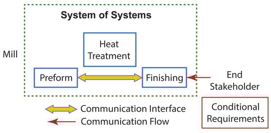
Figure 3.
Flow of information and active interfacing involved with material requirements.
2. Requirements for Evolving SoS (Task-1)
As mentioned before, more than half of the cost and material losses occurred at the finishing or machining step. This low performance forms the logical basis for beginning the evolution of the SoS. The improvement of cost and material efficiency in the machining portion of the SoS is the primary objective to improve Tier 1 Requirements of the SoS.
2.1. Evolution Requirement Statement
Lower cost and material losses associated with machining in the SoS.
2.1.1. Incremental Improvement within Existing SoS Architecture
A common initial design step with system of systems is to investigate an incremental improvement to the SoS, without altering the existing system architecture [1]. In the chance that sufficient improvement is achieved, more transformational SoS design activity may not be immediately warranted. This would mean that deficiency was isolated to an individual system and not warranting of the rigor of a SoS design. Even if unsuccessful, this may indicate a direction toward evolving the SoS. Namely, at the minimum provides an exploratory effort and forms what could be considered a root cause of the perceived system problem.
This initial step will be guided by our prioritized requirements defined in the Assessing Performance to Capability Objectives: Validation step performed prior. The two most important requirements indicated were cost and material efficiency. As a result, we look to existing performance regarding these requirements to highlight where initial improvement efforts may be applied. In the validation step, the finishing step was the most impactful for both cost and material efficiency. As a result, it is a logical extrapolation to attempt to improve the finishing system without altering the SoS.
In the finishing step (see supply/process chain discussed in this paper shown in Figure 4), in this case machining, material losses in the form of machined chips or stock constitute the largest source of material loss in the system. This system exhibits a subtractive process to remove excess and undesirable material to leave a component in the form desired by an end user. In this case, it may be possible to explore alternative methods of removal of titanium material, however, due to the common acceptance of traditional machining, the authors may leave this up to further studies and instead focus on improvements within the confines of traditional mechanical material removal.
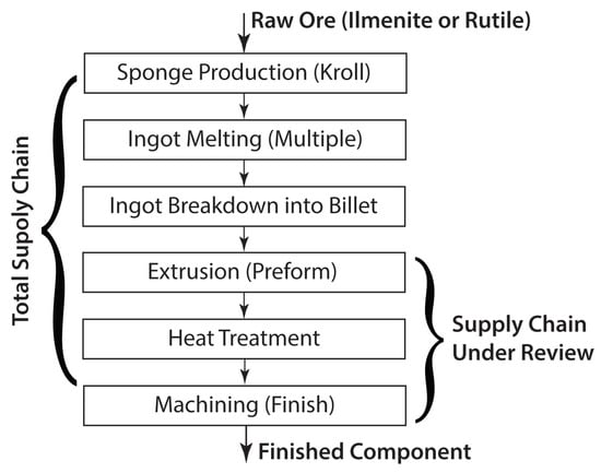
Figure 4.
Titanium supply chain.
Improvement of Machining Titanium: The machining of titanium is considered difficult regardless of the technique employed. The reasons for this perception originate from the response of titanium to the machining process. High flow stress and low thermal conductivity result in temperature concentration at tooling interfaces where deformation is concentrated [2]. The high friction coefficient with titanium further elevates the temperature at titanium cutter interfaces [2]. As a result, heat is highly concentrated at tooling interfaces which commonly results in rapid degradation of cutters [3].
Attempts at high-temperature machining to reduce stresses resulted in the formation of alpha case layers and expedited cutter failure. Elevated temperature machining is complicated given the copious amounts of lubricant required to preserve cutter strength [3].
To further inhibit machining effectiveness, the presence of any oxidized or highly alloyed surface layers have an abrasive effect and degrade cutting tooling [3]. Furthermore, titanium exhibits reactive tendencies at elevated temperatures. Above 533.2 K titanium will tend to react and destroy metallic cutting tools [2]. In addition to cutter degradation, the titanium’s surface quality will be drastically reduced if the reaction is allowed to persist [3].
Considerable work has been done around the best practices of machining titanium–the machine selection, cutter material, cutter condition, lubrication, and chip handling are all outlined to most effectively cut titanium [3]. However many limiting factors are a function of the materials themselves [2]. As a result, much of the costs and methods are inherently tied to the titanium. The material removed during machining is as much if not more a function of the pre-form performance, such as surface quality, dimensional and straightness control, and distortion during machining. As a result, the authors regard the improvement of the act of machining titanium as near an optimum and shift their focus toward other aspects of the system for improvement.
2.1.2. Need for SoS Improvement
Since the SoS design may need to be altered, the first aspect to address for a manufacturing supply chain is whether it is in an architecture that allows design optimization. It is not uncommon for manufacturing supply chains to be composed of independent companies or organizations that otherwise would not collaborate. Much of the resulting supply chains are lower order types. In the lowest order case, a virtual SoS, there exists no central management authority or agreed upon purpose. In this way, product changes hands blindly and without interaction, based solely on agreed upon conditions [1]. Because of previously identified interface communication, proposed SoS is of the next higher order or collaborative SoS. This way an agreed upon central purpose is fulfilled by the systems interacting voluntarily [1]. However, there is no evidence that central management authorities exist to oversee the SoS. To initiate a SoS level improvement, some central design authority must be present to guide decisions to the betterment of the SoS instead of for the individual systems. The next level of SoS type is an Acknowledged SoS. In this type of SoS, individual systems remain independent, but the SoS now has objectives, management, and resources [1]. The highest level SoS, a directed SoS, has the SoS level requirements at the highest priority and all constituent systems are largely subordinate to the SoS [1]. This may prove too rigid when systems are composed of separate companies or organizations and also have other supply chains they support. In the department of defense, it is uncommon to have SoS of the directed type as it requires system subordination to the SoS authority [1]. This is virtually impossible for entities of different companies, with distinct structures, shareholders, and objectives. However, in distinct cases where all systems are within one entity and are devoted to the specific SoS, the directed SoS structure would offer the highest level of supply chain optimization over the betterment of individual systems.
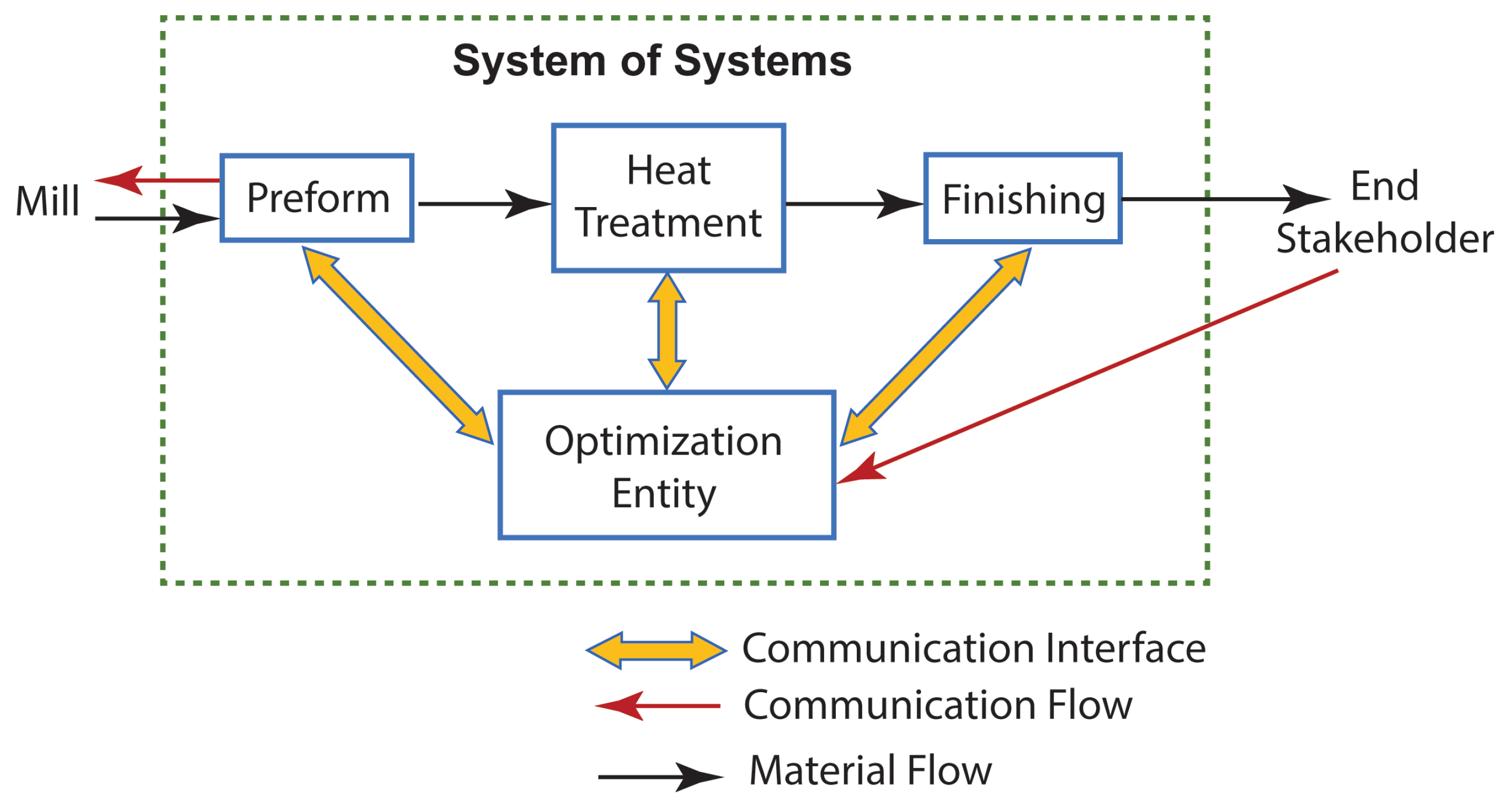
As a result, it is determined that to enact true SoS level optimizations within a manufacturing supply chain: the SoS must be elevated to an acknowledged level SoS. To do this, the architecture of the SoS must be modified to include an entity authorized to represent the best interest of the SoS. Figure 5 represents the new SoS architecture, interfaces, and material flow.
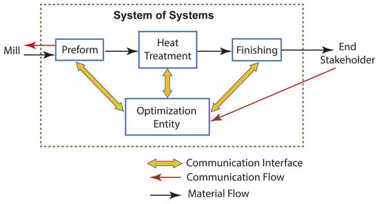
Figure 5.
Desired state of the system of system associated with optimum performance at manufacturing a titanium component.
With the new SoS architecture, the SoS level performance begins to be considered along with the performance of individual systems. Going into the logical analysis portion, the construct of the system should now be visited for the SoS to alter how the systems interact instead of looking at systems individually. Without this change, SoS level performance would not be prioritized. Instead, later stage systems would flow down requirements most advantageous of themselves, thus discouraging the advancement of the system with time.
3. Logical Analysis (Task-2)
Logical evaluation task is the second SoS design task as illustrated in Table 1. Given the requirement of reducing cost and material losses of the machining system, the SoS should be examined to determine what in the structure of the SoS may be causing this low performance. The logic being that it may be another systems interaction with the machining system that is causing the low performance.
The SoS has two primary functional interfaces. The first involves the coordination of the thermo-mechanical cycle of the titanium material. This has the predominant effect of establishing material properties of the final component. The second is the coordination of the preform geometry with the finishing activity. This activity is highly driven based on the capability of the preform process, performance of product through finishing, final requirements, and optimization of cost. Initially, this second relationship will be the focus as it has the most impact on the task of finishing or machining.
Initial attempts to identify an improvement strategy within the machining system were not overtly successful. In many ways, the parameters that govern the process of machining are well understood and predominantly driven by the titanium’s properties [2]. In the case, where the process of machining cannot be improved, a logical next step would be to attempt to reduce the amount of machining required. The amount of machining is the direct result of the collaborative interface between preform and finishing. The size and quality of the preform producible dictates what must be removed as the finished component is defined by the end user.
The machining step is meant to remove any surface condition of the extrusion deemed inadequate, the size given features to proper gauge, and improve dimensional control. Improving the preform quality enables the reduction in machining. Again, our attention is focused on the improvement of the preform system with the intent of affecting the performance of the machining system. The areas of improvement are minimum thickness, dimensional control, and surface quality for the preform. In the validation step, extrusion was used to build baseline performance of an existing SoS. As an initiation point, an extrusion system will also be used to evaluate for performance improvement initially.
3.1. Titanium Extrusion System
Early attempts at extruding titanium were aimed at performing below the beta transus. At these temperatures, titanium is considered one of the most difficult to extrude materials [4]. To improve material flow and lower flow stress of the material, the extrusion process began to be performed above the beta transition temperature [5]. This will significantly reduce many of the flow sensitivities of the material, velocity differences, and adiabatic heating within the material [5,6]. The improved forgability of the titanium above the beta transus is desired when attempting to produce components with very thin features size to minimize machining. As a result, beta extrusion is the desirable method of pursuit initially.
3.1.1. Design Parameters of Extrusions
When extruding titanium above the beta-transus, a number of factors must be considered. Temperature across the billet or primary material has an impact on exit velocity, surface quality and final microstructure in exaggerated cases [4,6,7]. Heat loss and adiabatic heat rise can be attributed to the variation of material temperature for an extrusion. Heat loss to the atmosphere during transfer to an extrusion press and heat losses to tooling drive surface cooling of the work piece [7,8]. The presence of a cold surface would be expected to pose more concern with very thin extrusion thicknesses as forgability would come into play. The second source of temperature variation lies in the generation of heat from imparting mechanical work during deformation. The balancing of minimizing heat loss and heat rise is done through the selection of ram speed for the extrusion [4]. The control of the numerous factors influencing temperature variation will directly couple with the ability to control flow and deliver robust gauge control [6].
Titanium along with steels and many refractory metals require glass lubrication. The glass significantly drops the coefficient of friction and reduces heat losses of the titanium [4]. Matching the lubrication to the intended work, reduces catastrophic defects such as scoring, galling, or other surface defects [9]. Without lubrication during sliding of titanium, the thin oxide layer breaks and bulk welding and tearing of the work piece occur [10]. However, with the friction reduction of glass lubrication, the glass lubrication also resulted in a coarsening of surface roughness of the extrusion. This is driven by glass buildup and surface entrapment phenomenon [9].
A key parameter to consider for beta worked titanium is the cooling rate following the extrusion process. Rapid cooling refines alpha lathe thickness within prior beta grains. Preservation of thin lathes helps preserve future hot workability [6,11]. The cooling rate also influences the room temperature properties of the titanium. As cooling rate increases, yield strength increases marginally. However, there exists an optimum cooling rate to maximize ductility of the titanium components. Ideally, the material should experience between a 5 and 9 °C per second cooling rate to maintain above desired levels [12,13].
Another aspect of extrusion is the surface absorption of oxygen of the material. At temperatures associated with extrusion, rapid absorption of oxygen into a highly alloyed alpha case layer [14]. The presence of the layer on the surface of the material diminishes fatigue performance and must usually be removed in some manner [9,15]. As employed prior to machining in this study, chemical milling, using a HF/Nitric Acid bath, is an effective method of removing this layer with only nominal increases in hydrogen content [14]. An alternative to chemical milling is the removal of surface layer through machining. However, the layer has an adverse effect on machining tool life [14].
A significant positive aspect of the extrusion process lies in the fact that rapid deformation occurs in the dynamic recovery region where all material has a BCC packing structure. Large amounts of non-uniform work can be inputted without the establishment of cracking, shear banding, or directionality [16]. This allows the formation of intricate geometries in the process without concern of material degradation.
3.1.2. Improvement of Extrusion Performance
The improvement of metal extrusions to exhibit the minimal machining stock required to yield a component has been widely pursued across the extrusion industry, and the general term of “Near Net Shape” has been coined to describe this. The general process of extrusion above the beta transition temperature, utilization of glass lubrication, and use of shaped dies forms the standard framework of industry practice. Recent developments have revolved around understanding material flow and understanding glassing requirements [4,6].
The development of extrusion dies for titanium has occurred incrementally. Historically the design of dies has been considered an art rather than a science [17]. The growth of understanding of contributing factors of tooling design on material flow has grown the ability to control and produce improved extrusions. The symmetry of entry geometry on orifice features was shown to have considerable influence on distortion [18].
The implementation of streamlined tooling resulted in significant improvement in material flow behaviors over other tooling geometries for lubricated extrusions. Flow stress levels, non-uniformity, and forces of the extrusion process were all reduced with streamlined die shapes [19]. Furthermore, there was found to be an optimum die geometry length to achieve optimum performance in extrusion. This was driven predominantly by frictional conditions [20].
3.1.3. Optimization Efforts
Given the increased understanding of extrusion process within the industry, industry entities have begun pushing the capability of extruding titanium. Recent efforts have begun to optimize the extrusion practice of titanium extrusion. Delaunay and Munch began efforts to enhance the capability of extrusions toward thinner profile thicknesses [21]. By addressing temperature uniformity, lubrication, and die geometry the minimum extruded thickness was improved from 6.86 mm–10.16 mm to 3.5 mm [21]. This improvement in thickness was achieved while maintaining dimensional control of a traditional extrusion [21]. This effort represents an optimization of the extrusion system through an optimization of the parameters of the extrusion process.
3.1.4. Limitations
Although through the optimization of the extrusion system there exists the potential to reduce the minimum extrusion thickness down to 3.5 mm, that does not necessarily improve the system of systems. Current methods of extruding titanium employ glass lubricants to reduce excessive friction and lessened defect rates for galling and tearing. This does, however, lower the maximum achievable surface quality in the extrusion [4]. In the paradigm of machining to remove poor surface quality a number of other parameters contribute to machining stock. The stock must be correlated with machining stock to ensure that no straightness condition results in failure to machine on all surfaces. The extrusion method, though very effective at producing shapes very close to final shape, do not produce surface qualities required by machined component applications due to the presence of glass [4].
This identifies the shortcomings of the SoS. The extrusion process capabilities of surface quality and dimensional control are not aligned with the requirements of a finished component [22]. Improving the surface finish and dimensional control of the pre-form made by the extrusion process would change design approach as machining stocks would not have to be sized to machine on all surfaces to achieve conditional requirements. Surfaces of the preform could remain untouched and machining stock could be eliminated in some cases, presuming straightness matched that of a finished component.
Assuming surface finish were acceptable, a final shortcoming is that even in the optimized case, a minimum extruded thickness of 3.5 mm was achieved. Though much improved, this minimum section thickness is not necessarily aligned with the section thickness of final components as would be necessary to have true SoS alignment. To expand that capability, it is also desirable to achieve thinner section capability, down to 2 mm or below.
4. Design Solution (Task-3)
So far, considerably more clarity has developed for understanding and attempting to improve the SoS. The next step, as illustrated in Table 1, is a true design activity to generate a new or modified path or approach for the SoS.
The benchmark system of systems represents the current method of producing structural beam from titanium, with existing capabilities of the extrusion and machining systems from which it is composed. However, the surface quality and dimensional control of an extrusion are insufficient to the requirements of a finished component. As a result, the machining stock is present to ensure this removal. If machining stock were insufficient to remove the extruded surface, the finished component would not meet the requirements of product leaving the SoS. Also, in instances where a thin component below 3.5 mm was desired, deterioration of many of the quality metrics of the extrusion would be expected as this represents the optimization limit [21]. However, this is what is desired based on proposed SoS requirement to reduce cost and material losses at the machining step previously outlined. For this research experiment, the thickness of 2 mm was chosen to be generally aligned with the thickness of many component features in titanium applications, and thus representative of an end state or final thickness of the supply chain. The material is often generalized as “Titanium” in this paper, is referring to Ti-6Al-4V. This is the most widely utilized alloy of titanium in the world. The combination of high flow stress, low thermal conductivity, low specific heat, high shear softening, and tendencies for cracking or porosity outside of narrow processing windows make it difficult to manufacture with.
Now, design methodologies will be used to suggest an evolution in the structure of the SoS to address the shortcomings. In this case, along with many others, performance within a SoS is driven by a compromise between constituent systems. In other words, improving one system while worsening another is a balance or optimization to the SoS. The TRIZ (Theory of Inventive Problem Solving) design method is designed to evoke resolutions when improvements are realized at the detriment of other factors [23]. This resolution of conflict rather than living with compromise aligns extremely well with the type of problems experienced in SoS. Hence, TRIZ is the primary design tool employed by the authors when working in SoS applications.
TRIZ is a powerfull empirical method of innovation for creative problem solving which draws on the past knowledge, initiative and skill of thousands of engineers to accelerate the project team’s ability to solve problems creatively in many fields. TRIZ brings reliability, repeatability and predictability to the problem solving with its structured approach. The range of TRIZ application generally deals not with advancement and development activity (development of technologies, industry, business, art and science, etc.) but with technology of creating something new, inventing methods which had been unknown before [24].
4.1. Framing TRIZ Contradiction for SoS Evolution
4.1.1. Improving Factor
Extruding thinner and closer to the finished shape would reduce the amount of material removed by machining. This reduction would reduce material removed and as an SoS the overall conversion efficiency. As a result, reducing or eliminating machining stock improves the loss of substance, in this case, titanium loss of substance is improving [23].
4.1.2. Worsening Factor
The reduction of machining stock is not without consequence in the SoS. Reducing this unchanged can result in remaining of the poor surface and failure to meet surface requirements. Pushed beyond the optimized case, reduction in dimensional control and surface quality would be expected. These worsening parameters would categorize into the object generated harmful factors feature [23]. Both dimensional control and surface quality are generated in the extrusion process and would be harmful to final component quality as the SoS is concerned [23].
- Object Generated Harmful Factors.
The TRIZ contradiction matrix suggests four of the forty inventive principles for this contradiction [23]. These four principles are listed below.
- (1)
- Segmentation
- (10)
- Prior Action
- (29)
- Pneumatics and Hydraulics
- (34)
- Discarding and Recovering
After careful review of the principles and how they might be applied to the SoS, the segmentation principle was selected as having the most potential method of pursuit for improving the SoS. This does not eliminate the other principles and could then be revisited if initial efforts are not successful [23].
The method of applying the segmentation principle was intended to apply to the preform process. Instead of the current method where the preform is generated with one system employing the extrusion process, this would be employed with multiple systems or processes that could collectively perform better than any individual system alone.
The use of two systems to produce the input for machining for the SoS could mirror the approach of the rolling of a steel sheet. Hence, the general slab of steel is rapidly deformed to close to a finished component in a roughing process. The product is then put through a finishing process to refine surfaces and get down to desired gauges [25]. In this way, the SoS would intend to get down to close to the finished component and add a finishing reduction to refine surfaces and achieve thin gauges aligned with a finished component.
5. Materials and Methods
The two constituent systems for rough forming and finish forming are integrated into a singular trial. The performance of the cumulative system of system should provide the functionality desired of the SoS as well as the constituent systems.
5.1. Extrusion
The extrusion was performed on a 5000T horizontal extrusion press. The tooling was designed for round input of 203.2 mm diameter. Glass frit was used on the exterior of the billet surface. A glass compaction was placed on the front face of the die for additional lubrication. The billet was transferred to the extrusion press via an automated loading system. Billet heating was performed using an induction heating system. Surface pyrometers viewing the outside surface of the billet were used as the control feedback for induction heater feedback. A continuous feed of argon gas system was attached to the induction coil to provide inert argon atmosphere.
The extrusion process selected for the SoS design was a beta extrusion that is close to the final component shape. A “T” shape section with extrusion thickness target of 5.28 mm, or 50% higher than published extrusion optimum was sought [21]. The section illustrated in Figure 6 was selected to be 95.25 mm wide and 47.63 mm high at extrusion to provide a sample of adequate size to obtain sufficient surface information. The objective of the experimentation was to roll the 5.28 mm extrusion shape to 2.54 mm thick in four passes.
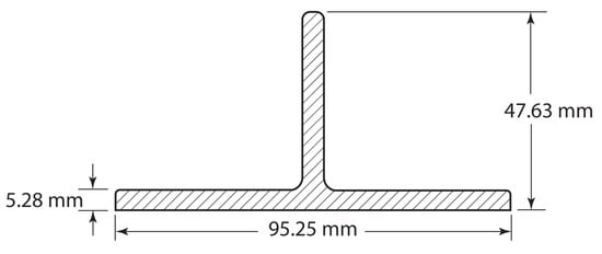
Figure 6.
Target extrusion shape.
For the extrusion system, a number of aspects of the system were planned as contributors to success. These planned parameters, as listed below, were successfully followed.
- Temperature above the beta transition temperature
- Rapid cooling following deformation
- Limited time exposure to high temperature
- Rapid deformation input
- Glass lubrication to be utilized
- Streamlined die geometry utilized
A temperature of 366.5 K above the beta transus was selected to ensure that entire billet remained above the beta transus in spite of minor heat losses during transfer as well as conduction losses to the extrusion equipment. Throughout the entire cross section uniform microstructure was observed. This validates that material was above the beta transus during deformation.
Extruded material was allowed to cool immediately following extrusion. The material of this thickness demonstrated the below surface temperature performance. The process of air cooling was successful at achieving surface cooling rate commensurate with maintaining subsequent workability. An observed cooling rate of 263 K/s at the beta transus is commensurate with the ideal cooling rate within the desirable range for beta worked material [13].
Induction heating occurred in nine minutes but occurred in an inert atmosphere to mitigate surface modification. Only the last two minutes of the heating cycle were actually above the beta transition temperature. The transfer to the extrusion equipment occurred in less than 60 s. Following the extrusion process, the above cooling process occurred. As a result, only 15 s above the beta transus were experienced on the surface.
Ram speeds of 152 mm/second were achieved. The entire deformation process was complete in less than 2 s. This deformation rate was sufficient to produce relatively fine grain sizes in spite of temperatures typically associated with rapid grain growth.
The glass was applied to the billet before deformation and in front of the extrusion die. Glass was observed coating the entire extruded component surface. Glass performance appeared to perform adequately at lowering friction and preventing major surface defects. Minor axial striations were observed but would be deemed acceptable pending the rolling process’ ability to remove them during reduction.
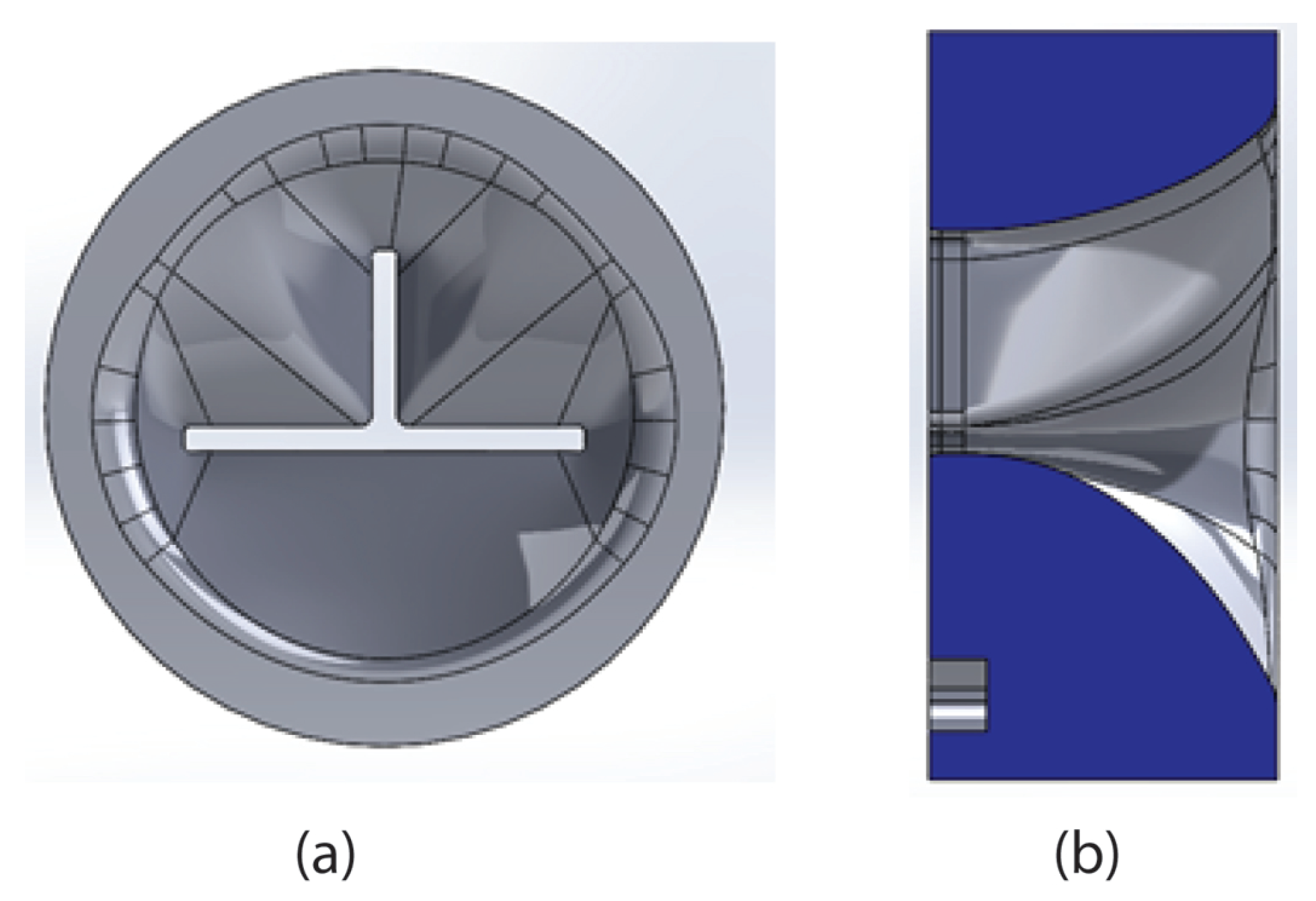
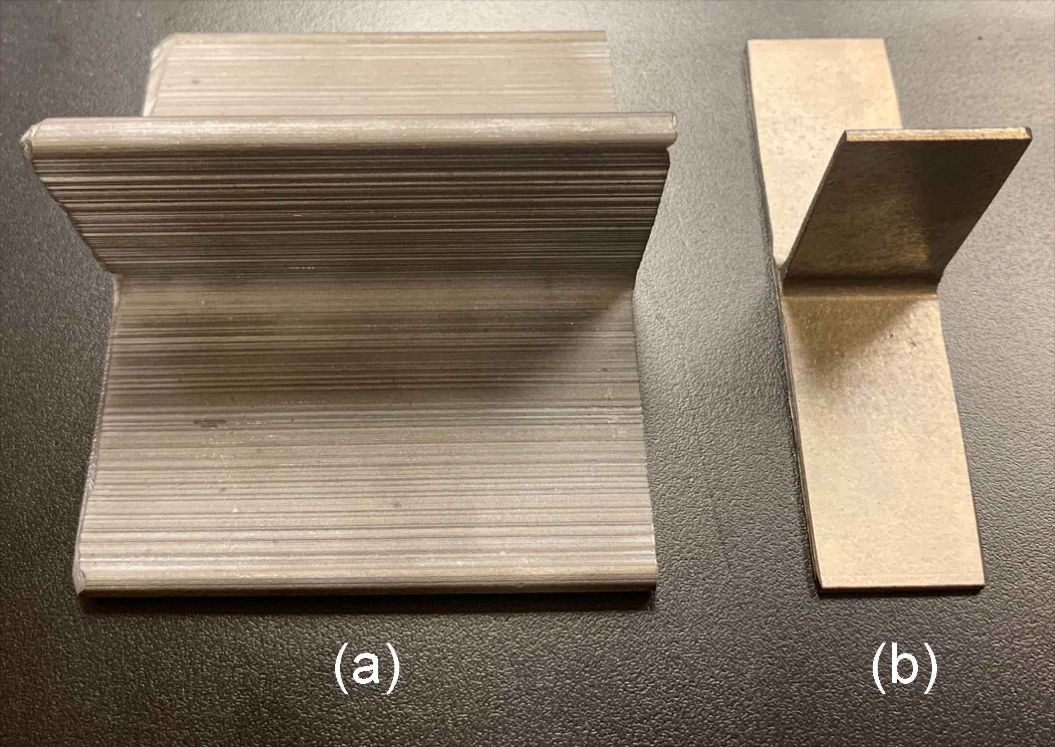
To ensure uniform material flow and sufficient geometric control of the extrusion, a streamlined die geometry of 76 mm thickness shown in Figure 7 was employed. This was maximum allowable by the load distributing tooling stack. The die proved effective at distributing material effectively through the shape. Limited flow variability was observed in the final extruded shape.
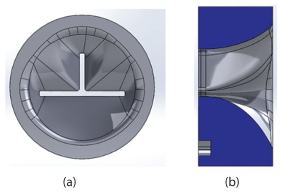
Figure 7.
Streamlined extrusion die from the front (a) and as sectioned from the side (b).
5.2. Rolling
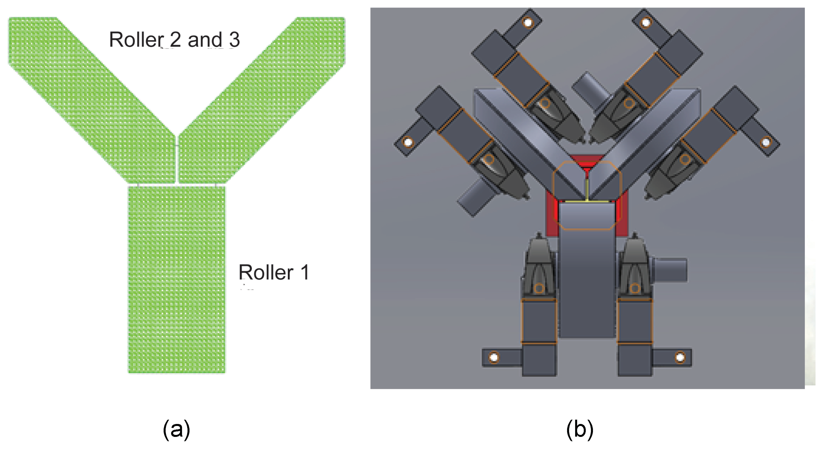
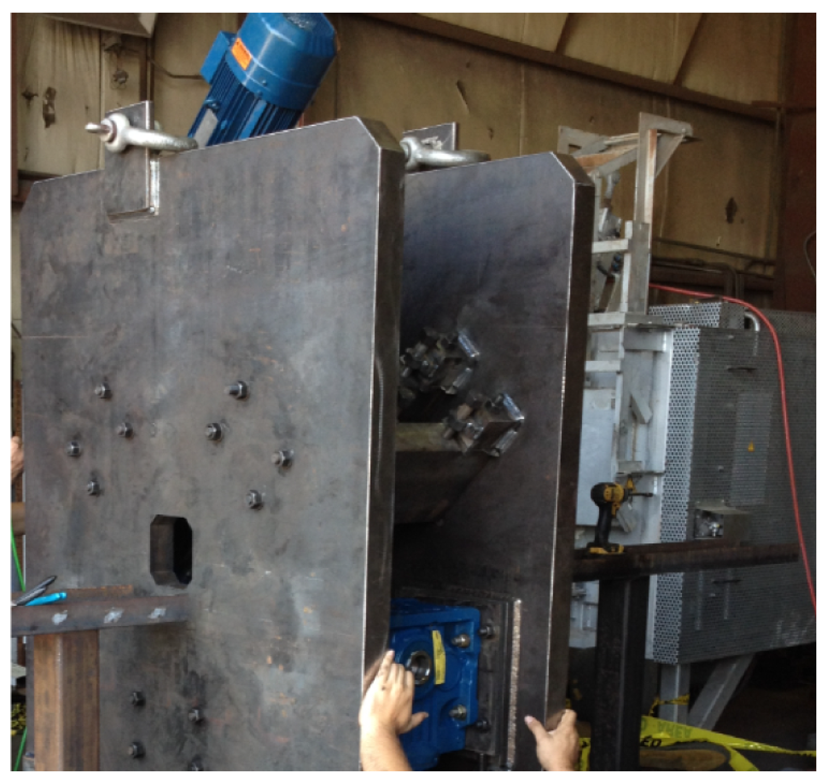
The rolling process was done using a universal type mill architecture. In this architecture, rollers are placed around the desired shape profile, as shown in Figure 8. Interlocking wheels yielded a gap between rollers. The product was passed through the gap to impart reduction throughout the section. The ability to advance the position of each wheel independently allowed for adjustment of individual feature thicknesses. The formation of parallel surfaces also allowed for the uniform reduction of non-tapered features, unlike in slotted rolling mills.

Figure 8.
(a) Schematic of interlocking wheels Around a T-shaped product and as sectioned from the side, (b) illustration of interlocking rollers along with bearing housing and cross bar supports.
The rolling system also had a number of aspects of the system that were identified as key parameters. These parameters were addressed in the trial, though some were purposefully not accounted for due to limitations in funding.
- Tight control of temperature uniformity
- Limited adiabatic heat generation
- Limited exposure to high temperatures
- Limited deformation input
- Elastic rigidity
- Precision Equipment
- Presence of surface scale
- Roller surface quality
The utilization of radiant atmosphere furnaces instead of induction heating was intended to better control temperature. The difficulty was expressed in previous effort holding temperature of complex geometries with induction heating units [26]. The furnace setup was able to consistently survey to +/−257 K. This allowed very precise control of component temperature.
6. Results and Discussion
Limiting adiabatic heating is directly a function of deformation input per pass. Considerable difficulty was seen in attempting to limit the range of deformation input. This parameter was tied to the variability in the flexure in the frame and the low fidelity adjustment techniques in roller positioning. Lower than the desired restriction of deformation input was observed, but not entirely unexpected due to cost related compromises that had to be made in the design of the experimental unit’s frame. Reductions, as low as 9% and as high as 27%, were observed in some cases.
The transition from the extrusion to the final shape was accomplished in four passes to keep reduction amounts between 15 and 20% to mitigate the potential for inhomogeneity during rolling resulting from adiabatic heat buildup. At a 20% reduction, the maximum potential for adiabatic heat rise is 285.4 K [104]. This forms the basis for keeping close to 15% reduction. The reduction schedule is outlined in Table 2.
Table 2.
Size changes and reduction amounts through the processing of the samples.
For each reduction pass, specimen were placed in a preheated oven to the desired temperature for eight minutes. It was expected that the components were at this temperature in three minutes or less. The remaining five minutes were to ensure temperature homogeneity. Following reduction, parts were immediately allowed to cool. Given that all specimen underwent passes, cumulative time exposure to heat was 32 min, plus time to cool—this was considered successful.
The limiting of deformation input from rolling was respected in all case. No specimen received more than 57.2% deformation from the rolling process. The average reduction was 51.8% for all specimens. This was accomplished through coordinating the extrusion shape with the rolling schedule of manufacturing.
While it is well understood what is required to produce a rolling unit capable of low elastic deflection, this was deemed cost prohibitive for a proof of concept trial. Very little academic uncertainty lies within this aspect of rolling mill design as elastic deflection mechanics are well understood. It was determined to not pursue this and instead prove the process by demonstrating titanium’s response to the process. This was left to future studies and production unit design.
Equipment was manufactured to tolerances of +/−0.127 mm for cost considerations. Pursuing tighter tolerances than this from manufacturers would have increased cost considerably. Given the known constraints on delivering a highly rigid structural frame, this tolerance was deemed sufficient for this research. Since delivering highly precise gage control is well studied and understood in the sheet rolling industry, this was decided also to be left for later study.
Since cleaning was performed following the extrusion process to remove glass lubricant remnants, no prior scale remained from previous thermal cycles. To reliably ensure a scale layer, an artificial layer was introduced. The fine mesh titanium dioxide powder was applied to the surface of the extrusion following glass removal through a standard medium mesh size grit blasting process. The fine powder seated in the micro texture created by grit blast allowed reliable mechanical bonding to the surface. This attachment of inert particles to the entirety of the surface successfully pacified the surface and lowered galling propensity. This practice was successful at ensuring protective scale layer for effective rolling.
Roller surface was manufactured to a 2.68 m roughness. This was selected as a compromise of desiring of smooth finish on the finished component and ensuring that sufficient friction was present to draw sections into the roll bite. Though this roughness is not considered an optimization by the authors, this was successfully executed to the plan.
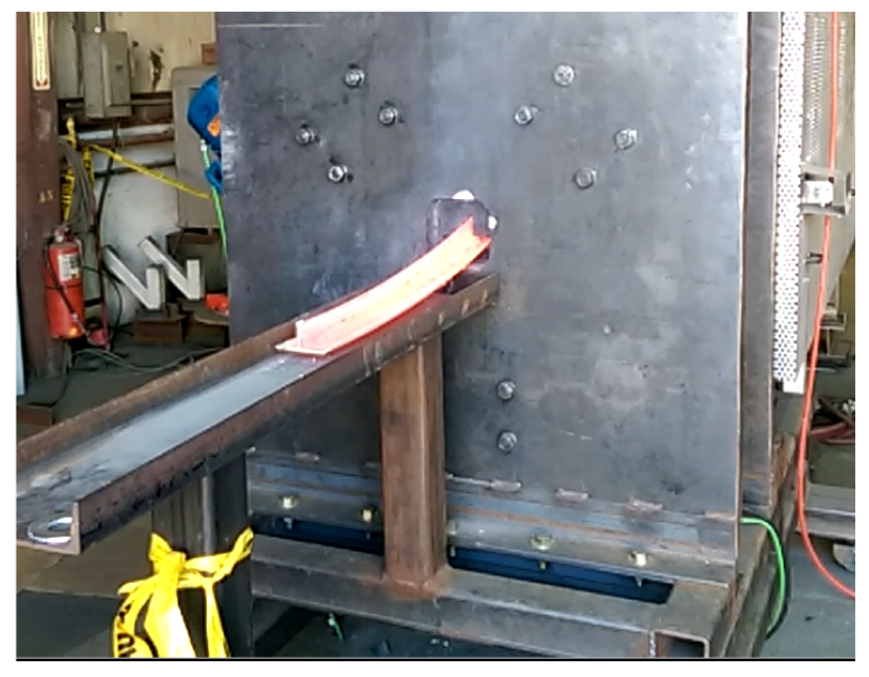
As shown in Figure 9, the rolling stand was mounted directly to the exit of an electric box furnace to minimize transfer time and subsequent transfer losses. Transfer distance between furnace and roll bite was just 381 mm long. The advancement of the product through the furnace was accomplished with a push bar from the back of the furnace. This provided the motion of the sample until the piece could be engaged by the rollers. The furnace design was that of an electric powered radiant box furnace. Temperature uniformity of +/−257 K was maintained at 1255 K. The exiting sample was ejected into a basin for cooling, as depicted in Figure 10. The expectation was that cooling in the air would be utilized to achieve the proper balanced cooling rate to maximize properties [13].

Figure 9.
Roll stand mounted directly adjacent to the furnace (light gray).

Figure 10.
Ejected sample into catch basin following reduction.
The performance requirements integrally tied to the overall performance of the system are the dimensional consistency and surface roughness performance of the resulting specimen. To establish the performance of the extruded product dimensional measurements were taken from each sample.
Following the rolling process, a targeted thickness of 2.54 mm was sought. Four reduction passes were utilized to reduce samples. The output material was measured, and the resulting thickness measurements were compiled for all sample cases. The targeted final rolling thickness was met. This system outpaced the capability of the prior art in the sense that a sample was manufactured beyond the published capability of an optimized extrusion system [21]. Following the chemical milling process to remove the alpha case layer, samples at 2.032 mm thick were reliably manufactured. This represents a significant improvement in the state of the art in minimum achievable thickness of a shaped component. Partially by design, the experiment did not demonstrate tight control of dimensional thickness across all specimens.
The rolling process, though demonstrating minor improvements, was not effective at bringing dimensional control to within the control of a final machine component. It was shown that +/−0.33 mm was required to encapsulate 95% of the population as compared to the requirement of no worse than +/−0.178 mm for the milled product [22]. In this way, the SoS requirement was not met, though not entirely unexpectedly for this trial. Rolling equipment design was not built for robust dimensional control for cost reasons for this effort.
The other characteristic of significance is the ability of the produce samples with surfaces commensurate of a finished component. The surface roughness was taken on the surface in the direction perpendicular to the extrusion direction. This is also perpendicular to extrusion texturing. The measurements of surface roughness were taken at four locations down the length and on both opposing sides of each feature. These measurements of surface roughness were taken at the same locations along the length at each step in manufacturing– to provide strong correlation of dimensional changes, or reduction, to the surface condition of the product. Following the thermo-mechanical processing of the product, a chemical etching process was employed to remove the alpha case from the product. Samples were measured following the conclusion of rolling and after chemical milling to characterize the effect that chemical milling process had on surface roughness.
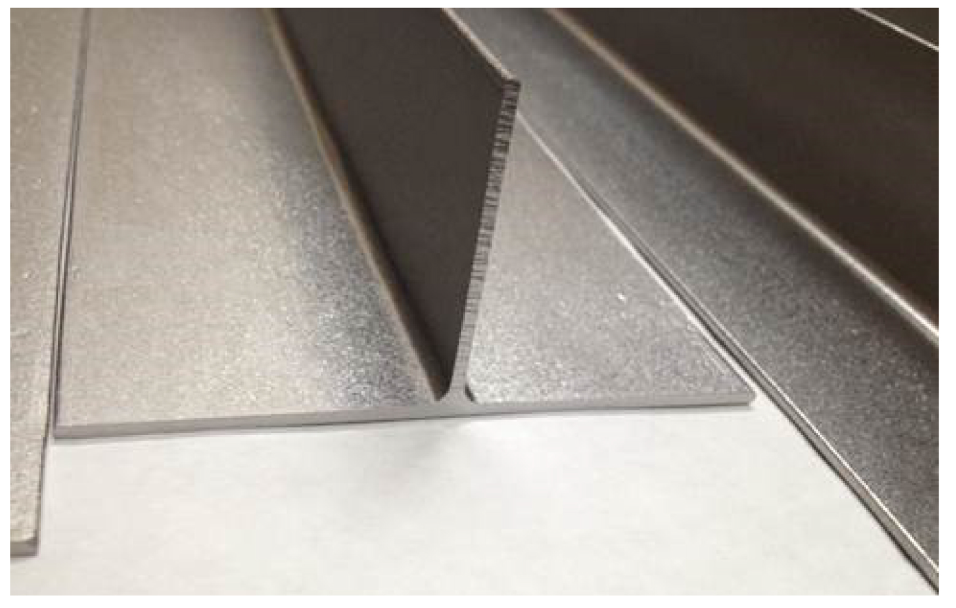
The extrusion surface quality was expected to yield lower quality due to the presence of lubrication. As illustrated in Figure 11a, during the extrusion process, axial striations were present on the surfaces of the extrusion. Axially aligned defects happen to be the best form of defect for rolling as this is the least likely to allow inclusion entrapment.
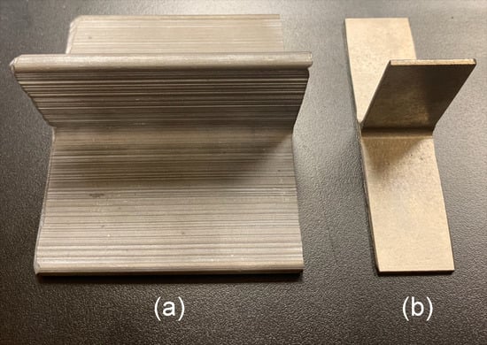
Figure 11.
Image of extruded surface (a) compared to the final rolled condition (b).
Following the extrusion process, the subsequent four roll reductions had a positive impact on the surface quality of the specimen as shown in Figure 11b. The final rolling pass was not the final stage of the processing as a chemical milling operation was planned to remove alpha case layers. Since all “as rolled” surface roughness of all specimen converged on the roughness of the rollers, regardless of the temperature or rolling speed during rolling, a sample was taken from each specimen for evaluation before and after a 0.254 mm chemical milling step.
7. Conclusions
Considering the first part of this paper, the structure of the approach aligned well with decomposing the true system conflicts into simplified engineering problems. The utilization of the system of systems design approach coupled with the TRIZ innovation technique proved effective at addressing the system constraints for the titanium manufacturing supply chain. The observed performances of the coupled system were:
- Minimum demonstrated rolled thickness down to 2.54 mm.
- Surface roughness smoother than 3.175 m.
- Lack of occurrence of shear banding or cracking.
- Successful elimination of lubricants for rolling without the occurrence of friction related defects.
- Presence of appreciable surface layers from heat loss to tooling in cases of slow roll reduction.
- Excessive grain growth and embrittlement of repeated rolling reductions above the beta transus.
- Material properties similar to extruded material when hybrid processing involving steps below the beta transus followed by a final step above the beta transus.
- Surface conditions, commensurate with a final machined component, are achievable through this method coupled with chemical acid etching (see Figure 12).
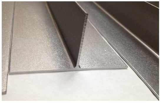 Figure 12. Image of surfaces for beta processed T specimen following roll reduction and chemical milling.
The utilization of the two part preform process prescribed by the system of systems design approach proved effective at addressing requirements and broadly stated industry needs. The coupled system aimed at delivering net shaped structural beam from common aerospace grade titanium. As illustrated in Figure 11b, this effort was highly successful.
Author Contributions
This paper was written from A.S. Ph.D. dissertation. A.E. was the advisor of A.S. A.E. wrote the paper using A.S. Ph.D. dissertations.
Funding
This research did not receive any specific research grant from funding agencies in the public, commercial, or not-for-profit sec-tors. Support of experimentation, including the use of equipment, was furnished by RTI International Metals, Inc.
Acknowledgments
Authors would like to express their special thanks of gratitude to RTI International Metals, Inc. for providing financial support for this project.
Conflicts of Interest
The authors declare no conflict of interest.
References
- Office of the Deputy Under Secretary of Defense for Acquisition and Technology, Systems, and Software Engineering. Systems Engineering Guide for Systems of Systems, Version 1.0; ODUSD(A&T) SSE: Washington, DC, USA, 2008. [Google Scholar]
- Machado, A.R.; Wallbank, J. Machining of titanium and its alloys—A review: Proceedings of the institution of mechanical engineers, Part B. J. Eng. Manuf. 1990, 204, 53–60. [Google Scholar] [CrossRef]
- Froes, F.H. Titanium: Physical Metallurgy, Processing, and Applications; ASM International: Materials Park, OH, USA, 2015. [Google Scholar]
- Chadwick, R. The hot extrusion of non-ferrous metals. Int. Mater. Rev. 1959, 4, 189–256. [Google Scholar] [CrossRef]
- Semiatin, S.L.; Seetharaman, V.; Weiss, I. Hot working of titanium alloys—An overview. In Proceedings of the International Symposium Sponsored by the Tms Titanium and Shaping and Forming Committees and Held at the 125th Tms Annual Meeting and Exhibition, Anaheim, CA, USA, 5–8 February 1996; pp. 3–74. [Google Scholar]
- Udagawa, T.; Kropp, E.; Altan, T. Investigation of metal flow and temperatures by fem in the extrusion of Ti-6Al-4V tubes. J. Mater. Process. Technol. 1992, 33, 155–174. [Google Scholar] [CrossRef]
- Hansson, S.; Fisk, M. Simulations and measurements of combined induction heating and extrusion processes. Finite Elem. Anal. Des. 2010, 46, 905–915. [Google Scholar] [CrossRef]
- Lenard, J.G.; Davies, M.E. The distribution of temperatures in a hot/cold die set: The effect of the pressure, temperature, and material. J. Eng. Mater. Technol. 1995, 117, 220–227. [Google Scholar] [CrossRef]
- Berry, J.T.; Pope, M.H.; Misra, N. Lubrication of titanium alloys under conditions of bulk plastic deformation. In Titanium Science and Technology; Springer: Boston, MA, USA, 1973; pp. 419–429. [Google Scholar]
- Roberts, R.W.; Owens, R.S. Boundary lubrication of titanium-titanium and titanium-steel. Wear 1963, 6, 444–456. [Google Scholar] [CrossRef]
- Semiatin, S.L.; Bieler, T.R. The effect of alpha platelet thickness on plastic flow during hot working of Ti-6Al-4V with a transformed microstructure. Acta Mater. 2001, 49, 3565–3573. [Google Scholar] [CrossRef]
- Titanium Alloy Extrusions and Flash Welded Rings, 6Al-4V, Annealed, Beta Processed; SAE AMS 4935K; AMS G Titanium and Refractory Metals Committee: New York, NY, USA, 2014.
- Sieniawski, J.; Ziaja, W.; Kubiak, K.; Motyka, M. Microstructure and mechanical properties of high strength two-phase titanium alloys. In Titanium Alloys-Advances in Properties Control; IntechOpen: Rijeka, Croatia, 2013; pp. 69–80. [Google Scholar]
- Witt, R.H. Current and future opportunities for near-net titanium P/M parts. Titanium 1986, 1987, 801–815. [Google Scholar]
- Seagle, S.R.; Yu, K.O.; Giangiordano, S. Considerations in processing titanium. Mater. Sci. Eng. 1999, A 263, 237–242. [Google Scholar] [CrossRef]
- Tamirisakandala, S.; Bhat, R.B.; Vedam, B.V. Recent advances in the deformation processing of titanium alloys. J. Mater. Eng. Perform. 2003, 12, 661–673. [Google Scholar] [CrossRef]
- Kavalauskas, R.; Gegel, H.L.; Doraivelu, S.M.; Malas, J.C.; Morgan, J.T. Use of CAD/CAM to Manufacture Streamlined Dies for Extrusion of Complex Materials; Society of Manufacturing Engineers: Dearborn, MI, USA, 1983. [Google Scholar]
- Damodaran, D.; Shivpuri, R. Prediction and control of part distortion during the hot extrusion of titanium alloys. J. Mater. Process. Technol. 2004, 150, 70–75. [Google Scholar] [CrossRef]
- Gunasekera, J.S.; Hoshino, S. Analysis of extrusion of polygonal sections through streamlined dies. J. Eng. Ind. 1985, 107, 229–233. [Google Scholar] [CrossRef]
- Gunasekera, J.S.; Hoshino, S.; Brown, R.H. Extrusion of non-circular sections through shaped dies. CIRP Ann.-Manuf. Technol. 1980, 29, 141–145. [Google Scholar] [CrossRef]
- Deluaunay, Christophe and Pierre Munch. Super Thin Near Net Shapes ITA; Calvi Holding Group Cefival: Milan, Italy, 2011.
- Oberg, E.; Jones, F.D.; Horton, H.L.; Ryffel, H.H.; Geronimo, J.H. Machinery’s Handbook; Industrial Press: New York, NY, USA, 2004; Volume 200. [Google Scholar]
- Altshuller, G.; Shulyak, L.; Rodman, S. Principles: TRIZ Keys to Innovation; Technical Innovation Center, Inc.: Worcester, UK, 2002. [Google Scholar]
- Ertas, A. Transdisciplinary Engineering Design Process; John Wiley & Sons Inc.: Hoboken, NJ, USA, 2018. [Google Scholar]
- Ginzburg, V.B. Steel Rolling Technology: Theory and Practice; Marcel Dekker Inc.: New York, NY, USA, 1989. [Google Scholar]
- Christiana, J.J. Improved Methods for the Production of Titanium ALLOY Extrusions; Republic Aviation Corp: New York, NY, USA, 1963. [Google Scholar]

© 2019 by the authors. Licensee MDPI, Basel, Switzerland. This article is an open access article distributed under the terms and conditions of the Creative Commons Attribution (CC BY) license (http://creativecommons.org/licenses/by/4.0/).