Review

Review of Aluminum-To-Steel Welding Technologies for Car-Body Applications

1
DISAT, Politecnico di Torino (Turin Technical University), It-10129 Torino, Italy
2
GML, Centro Ricerche FIAT (FIAT Research Center), It-10135 Torino, Italy
*
Author to whom correspondence should be addressed.
Metals 2019, 9(3), 315; https://doi.org/10.3390/met9030315
Submission received: 20 December 2018 / Revised: 15 February 2019 / Accepted: 23 February 2019 / Published: 11 March 2019
(This article belongs to the Special Issue Joining of Advanced High Strength Steels for the Automotive Industry)

Abstract

:
Hybrid car bodies fabricated by joining parts made with steel and aluminum alloys are becoming increasingly common. This provides an affordable mean to decrease the car weight by using lighter or more advanced materials only where they can achieve the maximum benefit. This development is driven mainly by recent regulations on carbon dioxide emissions, and hinges on the deployment of effective joining technologies. In most cases, such technologies were not previously used in the car sector, and must be adapted to its requirements. Several dissimilar welding technologies, based on either fusion welding or solid-state welding, are reviewed here, focusing on dissimilar joining among steels and wrought aluminum alloys. These technologies are either presently being introduced in the car industry, or are used in other sectors and could be applied in the car industry in the near future.

1. Introduction

1.1. Car Industry Context

Regulations of carbon dioxide emissions and fuel economy are becoming ever more stringent. Therefore, car manufacturers are increasingly trying new ways to decrease car-body weights, without loss of performance and avoiding excessive cost increases.
One prominent line of development in this respect is the introduction of multi-material (or hybrid) car bodies. In this approach, different parts are made not only with different alloys belonging to the same class, such as different steel grades, but rather, with entirely different material classes, such as steels and aluminum alloys.
Hybrid construction may make it possible to decrease the car weight at a moderate cost, by using lighter or more advanced materials only where they can achieve the maximum benefit.
Moreover, it can be more effective than full light-weight material construction (i.e., construction without steel) in order to reduce the total carbon footprint. In fact, hybrid construction makes possible the use of light but energy-intensive materials (such as aluminum) only in those parts where they offer the most important weight savings. As a consequence, their higher material production energy consumption and pollution can be effectively offset by the ensuing lower exhaust emissions.
In principle, the hybrid construction concept is amenable to all segments of the car-market. Regarding mass-produced cars, it would facilitate the application of light materials for those parts where the greatest mass reduction per unit cost can be obtained in otherwise steel-based car-bodies. Regarding premium cars, it would make it possible to retain some critical high-strength steel components for improved stiffness and safety in otherwise light-material constructions. However, for the above reasons, it is expected that it will have the greatest impact on the medium volume segment.
Present multi-material joining technologies in the car industry only are able to achieve very limited mechanical performance. This is true both in respect to the mechanical performance of the base materials and in respect to the most effective homologous welding technologies. Therefore, more extensive use of hybrid construction in the car sector hinges on the deployment of effective multi-material joining technologies. Such technologies in most cases were not previously used in the car sector, and must be adapted to its requirement.

1.2. Car Industry Requirements

Car bodies, as well as other car structures such as the doors and the main part of the car seat structures, are built by assembling many components. The latter components are most commonly manufactured by deep drawing metal sheets. Other processes, such as the hot forming of metal sheets, or processes specific to composite materials, are also used.
A wide range of steel grades, mostly fabricated in the form of 0.8 to 1.5 mm thick sheets, are most commonly used for car-bodies. Moreover, 1 to 3 mm thick aluminum alloy sheets are used for some lightweight cars. Finally, other materials (such as magnesium alloy sheets or carbon-fiber reinforced polymer laminates) are used only in premium or sport models fabricated in very small numbers.
Joining processes are used both to fabricate the tailor welded blanks (TWB), which are thereafter deep drawn to manufacture some parts, and to perform the final assembly. The two cases have different requirements.
In the TWB case, a continuous joining configuration is necessary, and butt joining is preferable over lap joining. Moreover, the two parts can be accessed from all sides and easily clamped, allowing large forces to be used if necessary). Finally, the plastic formability of the joint is of great importance.
In the final assembly case, butt, lap and edge joints can all be used in principle, but lap and edge joints are generally preferred because they allow larger mounting tolerances. Both linear (continuous) and pointwise (spot) junctions can be used. Linear junctions are preferable from a mechanical point of view, but spot junctions are more widespread due to less stringent mounting tolerances, lower cost and simpler tooling and execution. Moreover, during final assembly, access to the process zone is limited, giving an advantage to single-side processes, and the process forces must be low to avoid excessive deformation and complicated tooling. In the final assembly case, the plastic formability of the joint is unimportant.
Steel sheets are often zinc-coated before joining, whereas aluminum alloy sheets are generally not coated.
Resistance to atmospheric corrosion (after appropriate painting) is relevant for both TWB and final assembly junctions. Corrosion is much more critical for lap joints because they exhibit occluded interstices. Fortunately, in the steel-aluminum metallic couples, galvanic corrosion is naturally hindered by the aluminum passivation, and in principle it can be avoided if appropriate joining technologies and protective coatings are used.

1.3. Overview of Current Technologies

Presently, no multi-material joining technologies are in common use for TWB manufacturing. Moreover, the multi-material joining processes which are used for final assembly often exhibit poor mechanical properties with respect to the base materials.
In particular, multi-material joining in the car-body final assembly is performed in the vast majority of cases by either adhesive bonding or pointwise mechanical fastening (by clinching or riveting, or with fasteners). Mechanical fastening is inherently discontinuous, and therefore causes high local stress concentration. Moreover, adhesive bonding offers very low strength per unit area of adhesive in comparison with the strength of the base materials. As a consequence, the aforementioned techniques also require a large overlapping between the joined parts, which increases the overall mass.
Moreover, if long adhesive junctions between aluminum and steel parts were subjected to the paint-baking cycle, large deformation would arise due to their different thermal expansion. Adhesives which are in common use for multi-material joining in the car industry cannot withstand such deformation. For this reason, in these cases, contrary to all other present car-body joining processes, the adhesives cannot be applied before painting the car-body. This is a major constraint for the industry work-flow.
Nevertheless, aluminum to steel joining technologies based on welding processes have already been applied in a few cases in the car industry. For example, overlap friction stir welding of aluminum to steel was used in the front subframe of the Honda Accord model [1,2] (Figure 1). Furthermore, the resistance element welding technique has already been applied for the realization of the parcel shelf of the Volkswagen Passat model [3,4].

1.4. Scope of this Review

Several welding processes with different expected costs and levels of effectiveness are reviewed here. Some of these technologies are being recently introduced on a small scale in the car industry. Others are entirely new for the car industry, but have already been validated in the laboratory or in other industries, and are expected to deliver better performance than the abovementioned and now prevalent technologies
The review is focused on dissimilar joining among steel and aluminum alloys, because this couple is by far the most important for the automotive industry.
Moreover, the review is focused on welding technologies, i.e., those that form a metallic bond. However, hybrid joining methods, i.e., those that use a third metallic element to form a metallic bond on one side and a mechanical bond on the other, are also included.
The focus on the welding methods is due to two reasons. In the first place, the direct metallic bond can achieve a much higher strength (per unit area) than any other method. Moreover, the mechanical joining (e.g. riveting, clinching, etc.) and adhesive bonding methods are already well known, and were recently reviewed by Barnes and Pashby [5], Groche et al. [6], and He [7].
Those processes that are capable of creating continuous linear junctions are emphasized, because they allow a much larger joining section and a more even distribution of the service loads, avoiding excessive local stress concentration. However, spot joining processes are also examined because of their lower cost, less stringent mounting tolerances, and compatibility with the present widespread use of homologous spot welding.
Therefore, the following technologies are reviewed here:
-
resistance spot welding, for final-assembly;
-
resistance element welding, for final-assembly;
-
laser beam fusion welding, for both TWB manufacturing and final assembly;
-
electric arc fusion welding, for both TWB manufacturing and final assembly;
-
joining by means of transition joints, for both TWB manufacturing and final assembly;
-
magnetic pulse sheet welding, mainly for final assembly;
-
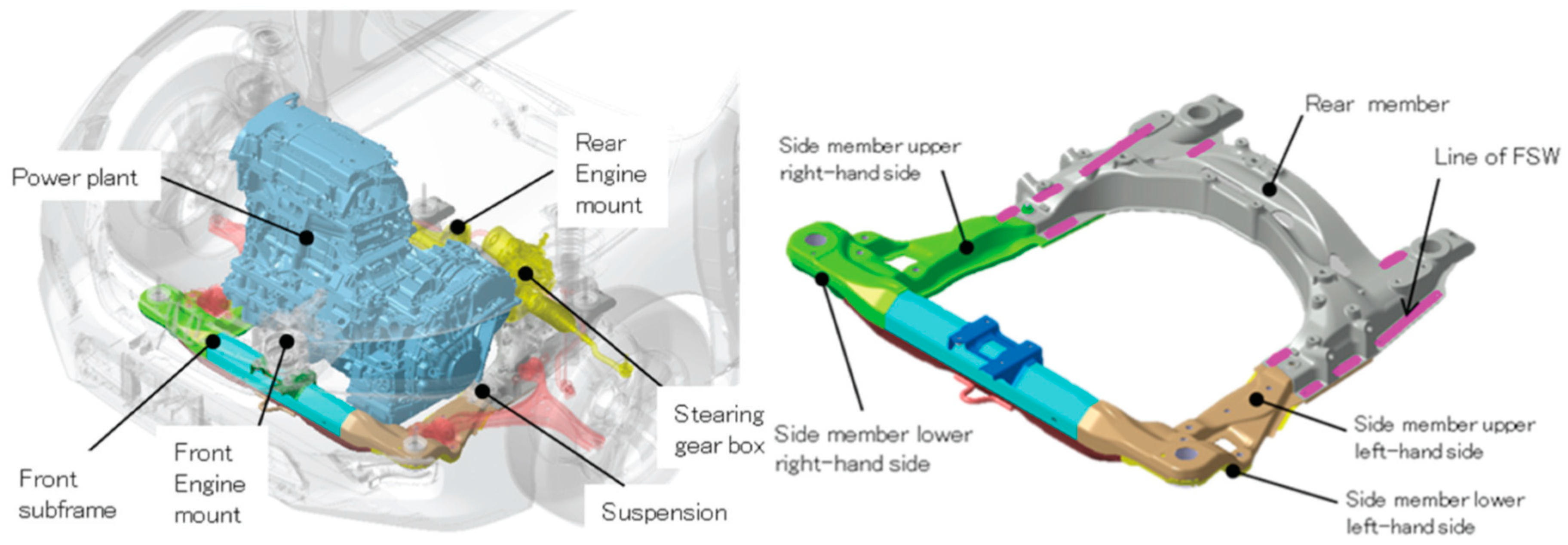
friction stir welding, including the spot variant, mainly for TWB manufacturing;
-
friction bit joining, for final-assembly;
-
ultrasonic spot welding, for final-assembly only.

2. Fusion welding technologies

2.1. Introduction

Fusion welding methods, and in particular the resistance spot welding technique, are commonly used for joining steel car bodies. Unfortunately, these techniques show important drawback when they are applied to hybrid welding between aluminum and steel.
According to the Fe-Al phase diagram (Figure 2) [8], the most relevant difficulty in the pursuit of a direct metallic junction between steels and aluminum alloys is the formation of inter-metallic compounds (IMCs). These compounds generally exhibit extremely low plastic deformability, and therefore, are a major cause of brittleness of the metallic junction. Therefore, it is important to minimize the IMC layer thickness, in order to achieve acceptable mechanical properties.
One further difficulty is the low wettability of molten aluminum on solid steel. This, luckily, can be improved by applying a thin zinc coating to the steel surface. Therefore, zinc coating is generally beneficial for fusion welding techniques (but not for solid-state welding).
For these reasons, fusion welding or brazing with some techniques, e.g., by resistance spot welding or arc welding, is difficult for steel-aluminum alloy couples, as IMCs are readily formed. Nevertheless, it can be performed under controlled conditions, in particular if the steel sheet is zinc coated (or aluminum coated) and a suitable interlayer or filler alloy is used. In particular, Al-5% or 12% Si or Zn-15% Al are commonly used filler alloys. Dong et al. [9], Su et al. [10] and Milani et al. [11] have shown that a relatively high amount of Si in the filler wire can reduce the diffusion of iron in molten aluminum, resulting in a reduction of the thickness of the IMC layers, and especially of the Al5Fe2 layer.
Sundman et al. [12] recently reviewed the Al-Fe system, showing that the possible Al-rich IMCs at room temperature are Al2Fe, Al5Fe2 and Al13Fe4 (the latter is sometimes called Al3Fe). Kouadri-David et al. [13] showed that the most critical region of a weld is that close to the aluminum side, where Al is prevalent but there is a significant Fe fraction. This happens because the solubility of Al in Fe is much greater than the solubility of Fe in Al, and because the Al-rich IMCs are brittle, while the Fe-rich phases (the α-Fe bcc solid solution and the FeAl and Fe3Al bcc ordered solid solutions) are relatively ductile.
The effectiveness of the different dissimilar welding methods is therefore especially (but not exclusively) related to their ability to avoid or minimize the formation of the aforementioned brittle IMCs, especially the Al-rich ones. In particular, Meco et al. [14] found that a thin IMC layer, i.e., thinner than 10 µm, does not generally compromise the strength and ductility of metal joints, whereas a thick layer can be detrimental.
For the above purpose, it is generally necessary to keep the process temperature and duration as low and short as possible, because the formation of the IMCs requires atomic diffusion, which is a time-dependent phenomenon which is greatly enhanced by temperature.
Hybrid fusion welding always involves melting the aluminum side and the filler or interlayer, if any, but it does not always involve melting the steel (in the latter case, it is sometimes termed ‘brazing’). Even if the steel is not melted, it nevertheless undergoes a chemical reaction with the liquid aluminum, forming intermetallic phases.
Fluxes are also often used in order to dissolve preexisting oxides, avoid in-process oxidation, and/or increase wettability.

2.2. Plain Resistance Spot Welding

As mentioned by Aslanlar et al. [15], resistance spot welding between homologous materials is one of the oldest welding processes; it continues to dominate the automotive assembly area. In contrast, this process is not presently applied to dissimilar metal couples in the car industry, with very few exceptions (see below). However, several investigations have been made at the laboratory scale.
Homologous resistance spot welding is most commonly applied between steel sheets. In the case of aluminum alloy sheets, due to their lower resistivity and higher thermal conductivity (in respect to steels), higher current densities are needed, causing an increase in processing costs. Moreover, aluminum oxides must be removed from the surface before welding, making the process yet more difficult and expensive.
Weld-bonding is a hybrid process that combines Resistant Spot Welding and Adhesive Bonding; it is widely used for homologous joints. The adhesive in weld bonding also seals the crevice, helping to avoid corrosion. There are two main ways of implementing the weld-bonding process. In the “weld-through” method, the adhesive is applied to the faying surfaces and the two sheets are assembled before spot welding. In contrast, in the “flow-in” method, the two sheets are spot welded first and then the adhesive is applied (flows) into the joint.
Regarding welding between zinc-coated steel and aluminum, Zhang et al. [16] found that plain resistance spot welding generally causes the formation of a brittle IMC layer, with thickness of the order of 5 µm. The IMC layer is formed at the interface between steel and aluminum, due to the reaction between liquid aluminum and solid steel, and the main IMC phases are Fe2Al5 on the steel side and FeAl3 (or Fe4Al13) on the aluminum alloy side, the former being thicker than the latter. The morphology and thickness of the IMC layer depends on the process parameters and on the distance from the spot axis; in particular, the thickness is generally higher at the spot center and lower on its outer boundary.
In the last few years, the General Motors car-building group patented three hybrid spot welding methods for automotive applications. Unfortunately, no mechanical properties were reported.
The first method, patented by Yang et al. [17], uses a ring-shaped electrode on the aluminum alloy side (Figure 3), which causes an increment of current density on the steel side. The different current density allows the concentration of heat on a smaller zone in the steel side than in the aluminum side. Therefore, the maximum temperature is attained inside the steel side, together with a high thermal gradient. At the end of the heating stage, the thermal gradient ensures the directional solidification of the aluminum (steel is not melted). Due to the directional solidification, the weld defects are driven in the center of the joint, where they are less likely to compromise the structural stability of the joint.
The second method was patented by Sigler et al. [18], and is shown in Figure 4; it makes use of a removable metal cover applied between the electrode and the aluminum sheet. The cover is made of an alloy which has a higher resistivity than aluminum (e.g., stainless steel, niobium, or tungsten), in order to generate more heat on the aluminum side. This method also affects the solidification behavior of the molten aluminum pool situated at the faying interface. The metal cover balances the heat generated through the workpiece, avoiding the accumulation of defects on the contact interface by confining them inside the weld nugget. The metal cover is fixed on the welding electrode, and can be used for one or more welding processes. When the cover is worn out, special tools are used to remove it from the weld electrode.
The third method, also patented by Sigler et al. [19], employs a multi-stage process of welding. The stages are: (1) electrical current flows between the steel and aluminum workpiece generating heat and melting a portion of aluminum located at the interface. (2) The electrical current is interrupted, allowing the melted aluminum to cool and solidify, forming the weld nugget. (3) The current restart to flow and the weld nugget (or at least a portion of it close to the contact interface) is re-melted. (4) The re-melted nugget cools and solidifies again. It is believed that this stage allows the minimization of weld defects, reducing the junction weakness. An optional stage, done between the third and fourth stages, consists of the expulsion of a portion of the molten aluminum along the interface between the two sheets, obtained by increasing the mechanical pressure, making it possible to eliminate the defects from the interface and to increase the welding strength of the joint.
General Motors started the first production application of hybrid aluminum-steel spot welding on a seatback frame part for the Cadillac CT6 car model [20], probably by using a combination of these patented methods.
Another recent approach is to use a process tape between the electrode and the workpiece. The process tape is a thin metal strip, which is moved on after each spot. All else being equal, the process tape is expected to increase the electrode’s life, decrease the spot indentation, and increase the heat input. The latter effect arises because the resistivity of the process tape is higher than that of the workpiece, and especially of the aluminum alloy sheets (similarly to the aforementioned removable cover technique). The process tape technique was introduced by a welding equipment supplier (Fronius, Austria), mainly for homologous welding, with the trade name “Delta-Spot”, and has been recently proposed for hybrid welding.
Kim et al. [21] tested several Cu alloy tapes and Cr-Ni alloy tapes on the steel and aluminum side, respectively, while welding DP590 steel grade to 5052 aluminum alloy, and reported a 64% increase of the cross-tensile strength in respect to RSW without process tape.
Che et al. [22] used carbon steel and stainless steel tapes on the steel and aluminum sides, respectively, while welding DP980 steel grade to 5083 aluminum alloy, and reported an 11% increase of the tensile shear strength. They also observed an IMC layer at the steel/aluminum alloy interface, and confirmed that the main IMC phases are Fe2Al5 on the steel side and Fe4Al13 on the aluminum alloy side, with the former being overall prevalent.

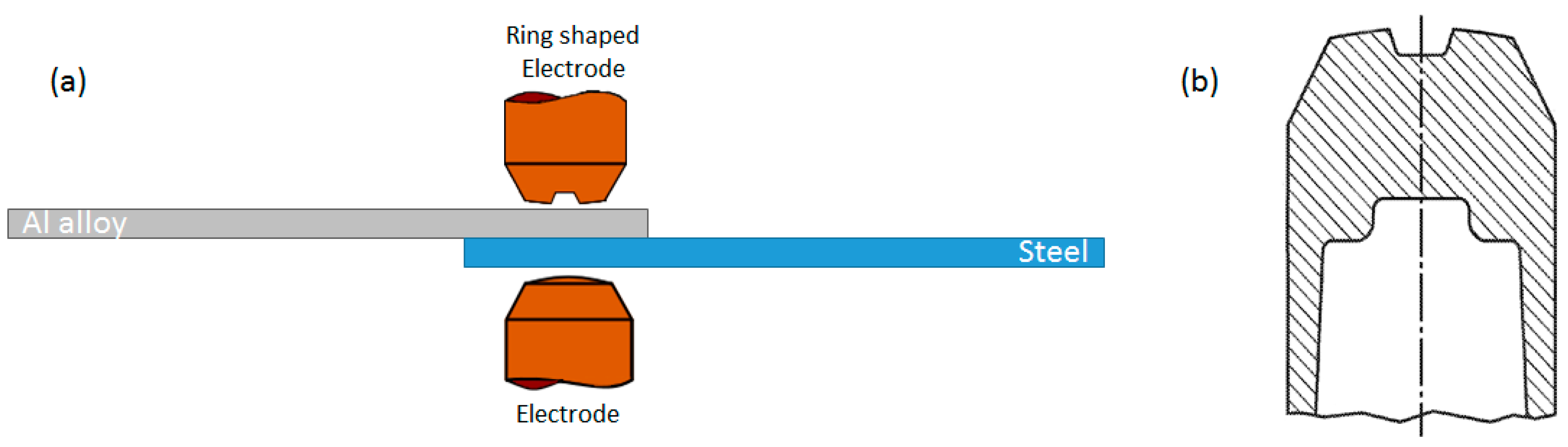
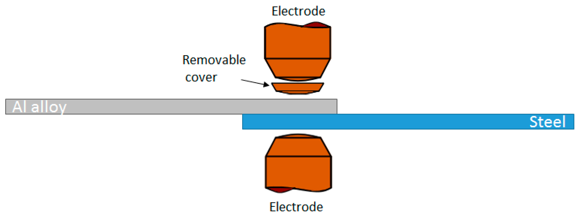
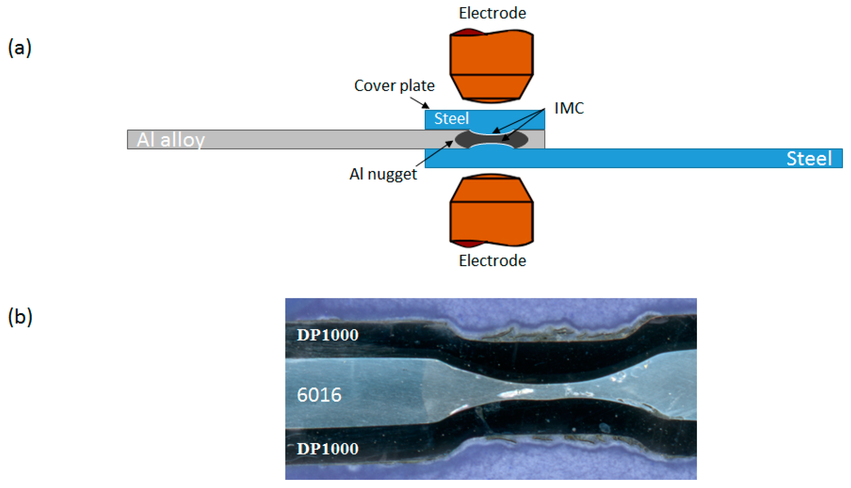
2.3. Resistance Spot Welding with Cover Plate

The cover plate method, which was investigated by Qiu et al. [23,24] generates greater heat input into the metal sheets despite the high electric conductivity of the aluminum. An example of an Al-Fe junction, obtained by the cover plate method, is shown in Figure 5.
Because of the low resistivity of the aluminum alloys, a large electric current is normally required to generate enough heat to join together aluminum and steel sheets. The high current density causes a reduction of the electrode’s tip life, affecting the production costs. A solution to these problems is provided by using a steel cover plate placed on top of the aluminum sheet so that both electrodes act on steel layers. The high electrical resistivity of the steel cover plate guarantees greater generation of heat close to the melting zone, allowing the formation of a welding nugget with a large diameter. Furthermore, the low thermal conductivity of the steel reduces the heat loss
Qiu et al. [23,24] carried out joining experiments between A5052 aluminum alloy and SPCC cold rolled steel, both having 1 mm thickness. The nugget diameters and the mechanical properties were affected by the current density. Good results were achieved by 11kA current, obtaining a nugget diameter of about 9.5 mm. Concerning the formation IMCs, it was found that they do not affect the tensile shear strength while they greatly affect the cross tensile strength. Similarly to plain RSW, the interfacial IMC layer was formed mainly by a thin (≈ 0.2 µm) layer of FeAl3 (or Fe4Al13) fine crystals on the aluminum alloy side, and by a thicker layer (≈ 3 µm) of Fe2Al5 large grains on the steel side.

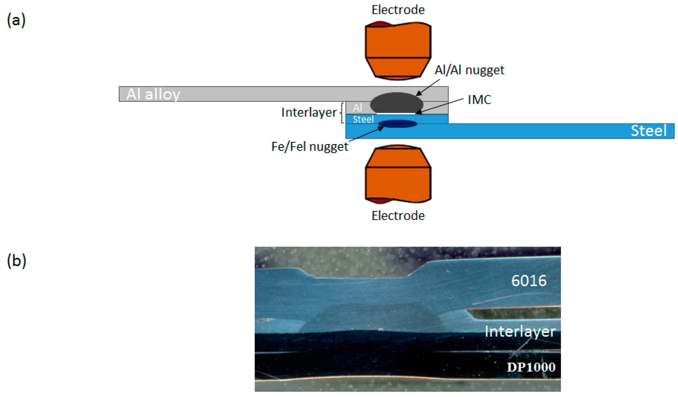
2.4. Resistance Spot Welding with Interlayer

Several RSW processes based on the use of an interlayer between the aluminum alloy and steel sheets have been proposed.
Zhang et al. [25] used a 0.3 mm thick, 12% Si aluminum alloy foil as an interlayer between zinc-coated, 1.0 mm thick, H220YD steel sheets and 1.5 mm thick, 6008 aluminum alloy sheets. They obtained a thin IMC layer (0.5 - 1.5 µm), as well as a maximum tensile shear load of 6.2 kN; however, fractures always occurred the IMC layer. Ibrahim et al. [26] also achieved an efficient spot joint by using a thin Al - 20% Mg alloy interlayer, ensuring better tensile and fatigue properties compared to Al-steel joints without a welded interlayer under the same welding conditions.
In most instances, however, a bimetallic interlayer, such as an aluminum clad steel sheet, has been used to increase the compatibility between the steel and the aluminum alloy and, therefore, the mechanical properties of the metal joint. This transition element is normally fabricated by roll bonding, a solid-state welding technique which is explained in Chapter 5.
In order to achieve a suitable joint, Haynes et al [27,28] and Oikawa et al. [29] found that the thickness of the aluminum cladding should be 40% to 60% of the total thickness of the bimetallic sheet. An example of this welding method is shown in Figure 6.
Aluminum cladding thickness of about 20% was also tested by Sun et al. [30], but was not considered optimal for the joint mechanical properties.
Oikawa et al. [29] demonstrated that despite brittle IMCs of 5µm thickness are formed on the aluminum-steel cladding interface close to the spot axis, the strength of the joint is similar to that achieved by homologous aluminum-aluminum RSW joints. The main IMC phase was Fe2Al5, consistent with the aforementioned investigations on RSW joints (other phases, if any, were not investigated).
An important advantage of this welding method was noted by Baboian and Haynes [31]. They reported that the bimetallic interlayer leads to the creation of a junction with high corrosion resistance, because only aluminum-aluminum and steel-steel crevices are formed, not aluminum-steel ones.

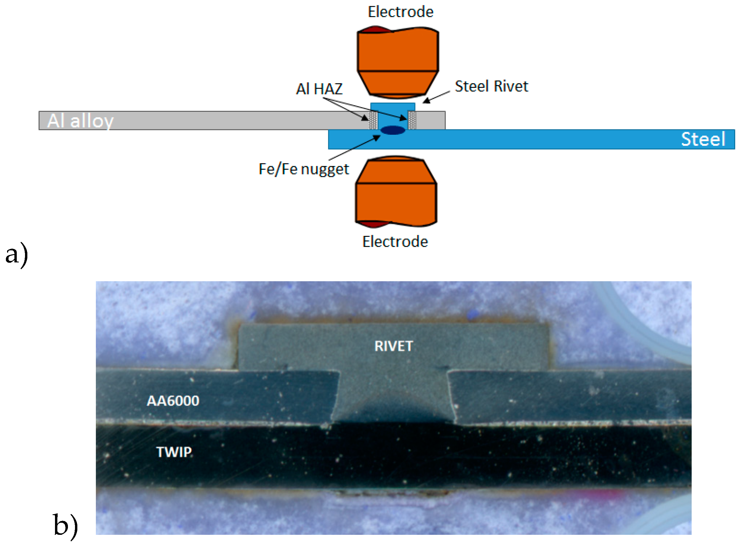
2.5. Resistance Element Welding

Meschut et al. [32,33] and Ling et al. [34,35] have investigated a variant of the resistance spot welding method, called resistance element welding (REW), in which the aluminum and steel sheets are joined by a steel rivet, which is welded on the steel sheet.
First, a hole is drilled or pierced in the aluminum sheet. Subsequently, as shown in Figure 7a, the rivet (having about the same radius) is placed inside the hole and put in contact with the bottom steel sheet. After that, spot welding is performed between the rivet and steel sheet. As a result, a suitable weld nugget is formed between the rivet and the steel sheet, and both are mechanically interlocked with the aluminum sheet (Figure 7b).
The current density for this process in generally lower than for spot welding between aluminum and steel. Moreover it is possible to avoid the cleaning of the contact surfaces before the joining process, and the steel sheet need not be galvanized.
Under an optimized welding process, the weld nugget will be strong enough to avoid any interfacial fracture. The fracture will thus occur in the (weaker) aluminum alloy sheet.
Resistance element welding is already applied in the automotive industry for the realization of the parcel shelf of the Volkswagen Passat B8 sedan [3,4].

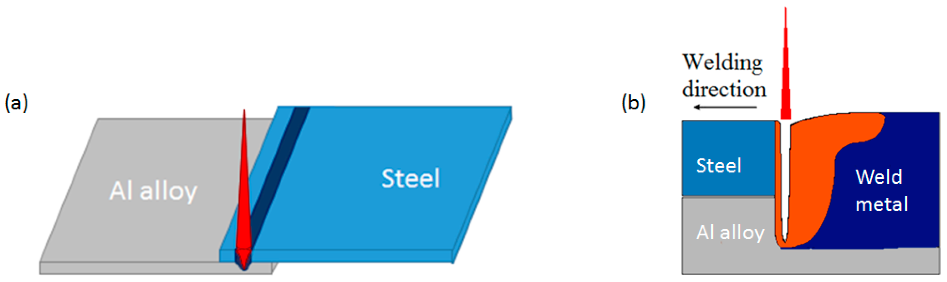
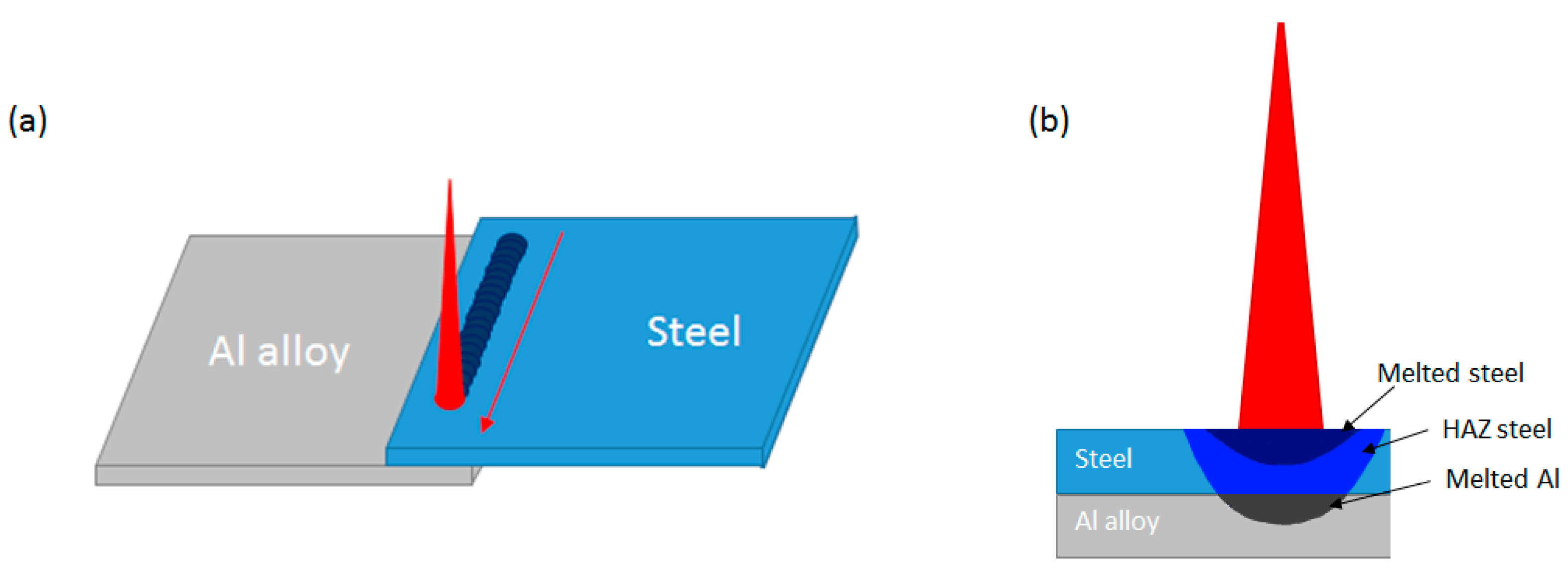
2.6. Laser Beam Welding

Laser welding creates a continuous seam weld while minimizing the width of the heat-affected zone (which may help to decrease the roughness of the welded surface and to increase the mechanical performance). Laser material processing techniques were reviewed by Ready et al. [36]. In automotive assembly lines, a laser beam coming from a remote source can be guided and focused on the workpiece, achieving high welding speeds and productivity. This method, which is called remote laser welding, has been reviewed by Zaeh et al. [37], and is used for a wide range of automotive applications such as closures, pillars, and seats.
Laser welding in the automotive industry is presently limited to homologous welding, but several investigations have been made at the laboratory scale on the issue of dissimilar laser welding. Regarding welding between zinc-coated steel and aluminum, for automotive applications, different techniques have emerged in the scientific literature: keyhole welding, conduction mode welding, reactive wetting and welding with filler metal.
In the keyhole welding method, proposed by Sierra et al. [38], the laser is focused onto the steel side, a keyhole is formed, and both metals are melted; this is illustrated schematically in Figure 8. Kouadri-David [13] observed that the fusion zone exhibit a large iron fraction, which is beneficial because the iron-rich phases in the iron-aluminum system are less brittle than the aluminum rich ones. Yan et al. [39] found that the thickness of the IMC layer is of the order of 10 µm. Yan et al. [39] and Torkamany et al. [40] performed welding tests with various combinations of process parameters, including pulsed and continuous laser sources. The joint tensile shear strength achieved by Yan et al. [39] was up to about 50% of that of the aluminum alloy sheet. Thin metallic strips (such as nickel and copper) can also be used between aluminum and steel sheets, making it possible to achieve better tensile force and toughness.
After keyhole welding, Sierra et al. [38] identified the FeAl phase in the weld metal, and the FeAl3 and Fe2Al5 intermetallic compounds at the interface between the weld metal and the aluminum alloy base metal.
In contrast, the conduction mode welding method is based on the different melting temperatures between steel and aluminum (respectively ≈ 1538 and ≈ 660 °C). A defocused laser beam acts on the steel side with a low power density, keeping the steel in the solid state (at least at the aluminum/steel interface), but melting the adjacent aluminum, as shown in Figure 9. The reaction of molten aluminum and solid steel connects the two sides. This method was investigated by Fan et al. [41] and by Meco, Pardal et al. [14,42,43].
Moreover, in the reactive wetting method, the laser beam is focused on the aluminum alloy sheet, and the liquid aluminum alloy reacts with the underlying solid steel surface. This method was investigated by Peyre, Sierra et al. [44,45], Kouadri-David [13] and Weller et al. [46].
A similar technique involves the use of a filler alloy, which is most commonly an aluminum alloy with 5% or 12% silicon. In this case, the joint is obtained by fusion welding on the aluminum side, and by the reaction between the liquid filler alloy and the solid steel surface, on the steel side. Both lap welding and butt welding are possible; the former was investigated by Sierra et al. [47] and Mathieu et al. [48,49], the latter by Sun et al. [50], Zhang et al. [51], and Li, Xia, Tan et al. [52,53,54,55,56].
Sierra et al. [47] used aluminum potassium fluoride as a flux, and Fan et al. [41] used special tools. Pardal et al. [42] reported that the mechanical properties of the joint could be increased by 25% if the steel surface is treated beforehand with a pulsed laser to create a particular surface texture, which increases the junction area.
In both conduction mode welding and reactive welding, IMC interfacial layers are formed as a consequence of the reaction between liquid aluminum alloy and solid steel. After heat conduction welding, Meco, Pardal et al. [14,42] observed a thicker Fe2Al5 layer on the steel side and a thinner FeAl3 layer on the aluminum alloy side. After reactive wetting, Peyre, Sierra et al. [44,45] and Kouadri-David et al. [13] observed an IMC layer formed mainly by Fe2Al5, and Peyre et al. [44] also observed smaller FeAl3 crystals on the aluminum alloy side in some instances.
The zinc layer is beneficial in reactive welding techniques, because it increases the wettability of liquid aluminum on solid steel. In contrast, the zinc layer is sometimes detrimental in the keyhole technique, because its evaporation may cause porosities and defects in the fusion zone. Kouadri-David et al. [13] used a strictly controlled gap between the two sheets in order to provide an exit route for the zinc vapor, avoiding the latter problem.

2.7. Arc Welding

Electric arc welding, similarly to laser beam welding, has been applied in the automotive industry between homologous materials (usually steel), but not commonly for dissimilar metal couples. In general, conventional arc welding is expected to be less effective than laser welding for dissimilar couples, because it generally results in a larger heat input. The latter causes the formation of a thicker intermetallic layer at the interface between steel and aluminum.
However, a pulsed arc welding technique has been recently developed and commercialized by a welding equipment supplier (Fronius, Austria), specifically for dissimilar welding, and in particular for the steel-aluminum couple. This method is similar to gas-metal arc welding, but it uses a pulsed electric current synchronized with a discontinuous wire feed system in order to minimize the heat input for the same amount of filler material input. This technique has been tested in the last years by Zhang et al. [57,58], Lin et al. [59], and Yang et al. [60], as well as by some car makers, but has not been widely adopted for industrial production yet.
Suitable alloy fillers are used for hybrid arc welding applications in order to minimize the formation of IMCs (see discussion above, chapter 2.1). In particular the Al - 5% Si and Al - 12% Si filler alloys are commonly used, and were investigated by Zhang et al. [57], Dong et al. [9], Lin et al. [59]. Alternatively, and Dong et al. [9] also investigated Zn - 15% Al alloys.
Zhang et al. [57] found that Fe2Al5 was the main IMC phase, and also observed smaller amounts of FeAl2 and FeAl3 where the heat input had been greater.

3. Solid-State Welding

3.1. Introduction

The mechanically most effective joining method for the Fe/Al couple is solid state joining by means of explosive impact welding, magnetic pulse impact welding, roll bonding, or friction stir welding. These technologies can provide a direct metal-to-metal contact with adequate pressure, and hence, yield a permanent metallic bond, while the limited temperature increase and the near-absence of liquid metal hinder the development of IMCs.

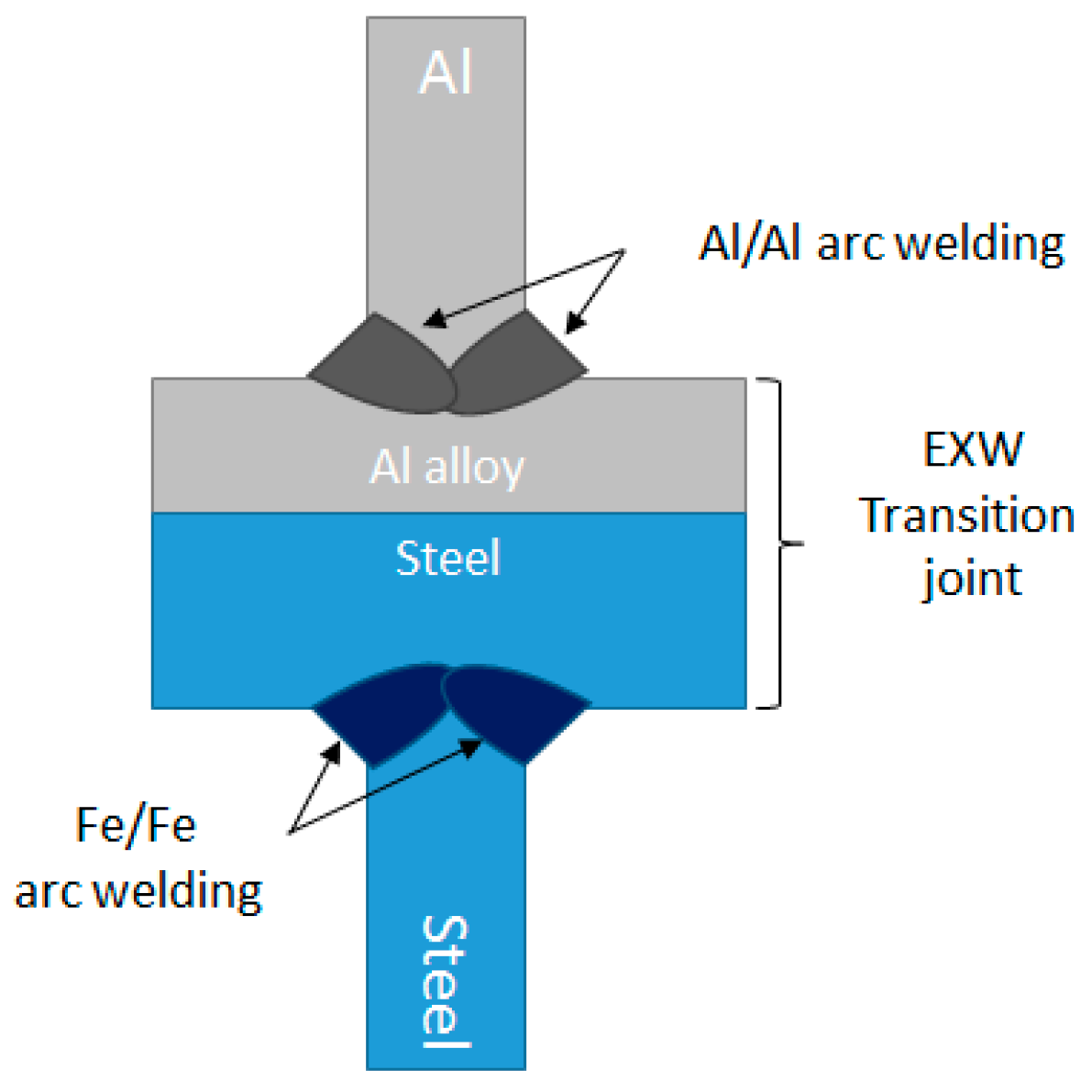
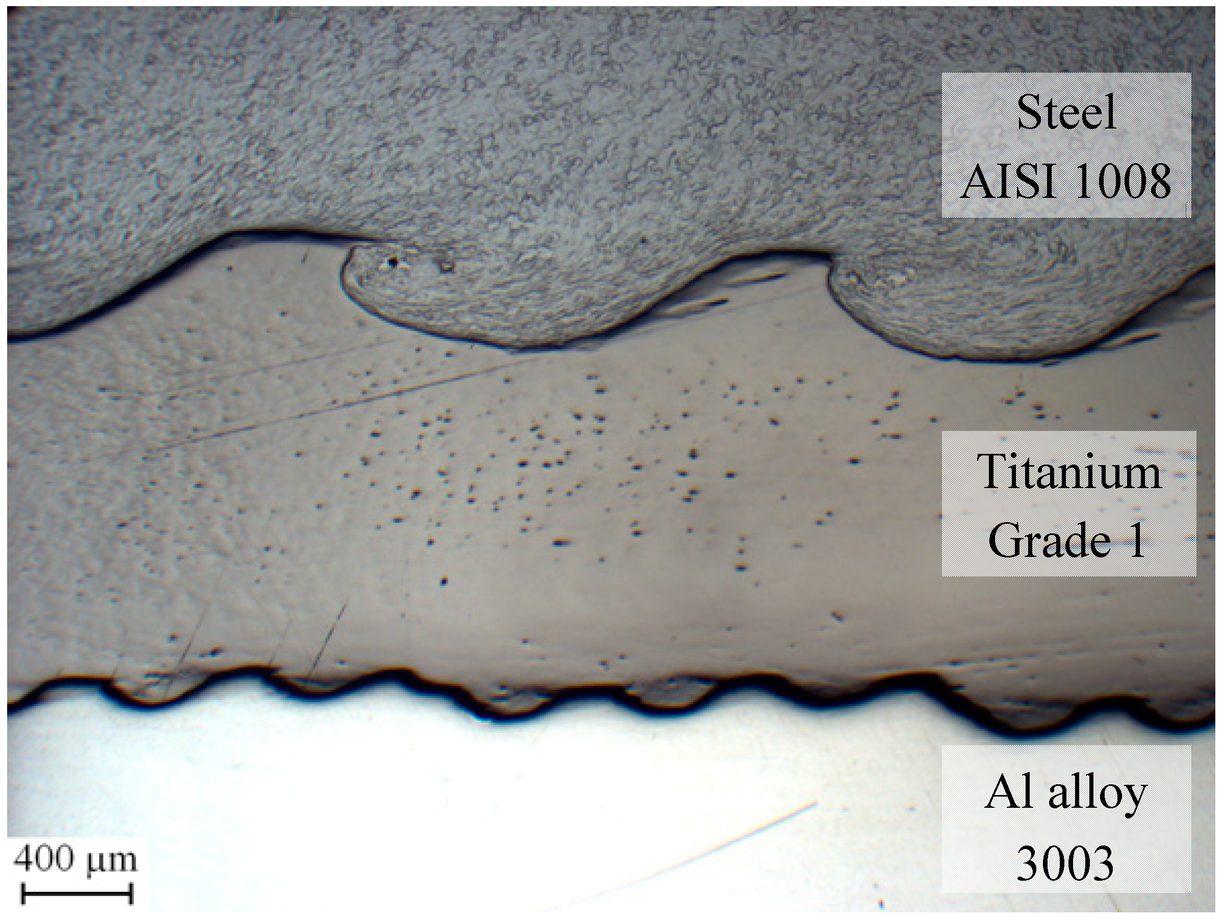
3.2. Explosion Welding and Transition Joints

In the explosion welding process, a “flyer” metal sheet is accelerated by an explosion, and collides at high speed with a “parent” metal sheet, cleaning the surfaces of oxides and contaminants and facilitating metallic bonding. Therefore, there is no external heating and the weld is achieved primarily due to the high collision speed. Findik [61] recently reviewed the fundamental parameters and recent development of this process.
Straight, IMC-free, diffusionless steel/aluminum alloy junctions can be obtained by explosive welding, as confirmed by Acarer [62]. In contrast, Tricarico and Spina [63] found isolated IMC-rich regions on wavy interfaces (the occurrence of straight or wavy interfaces depends mainly on the detonation speed).
Unfortunately, explosive welding is not suitable to be directly applied in the car industry, because of geometrical limitations and of safety concern on the use of explosives. However, pre-fabricated Fe/Al transition joints have been employed for a long time in the shipbuilding industry. These joint are bimetallic strips, which are cut from large explosive-welded plates, perpendicularly to the welding plane. They are mounted in between the steel hull or deck and the aluminum alloy superstructure, and are conventionally welded on both sides (Figure 10).
A similar concept, albeit with smaller bimetallic strips and different base material, could in principle be applied in the car industry.
A key feature of transition joints is their resistance to the formation of IMCs on the original bimetallic interface during the heating caused by the subsequent conventional welding processes performed on their sides.
As reported by Han et al. [64], Aceves et al. [65], and Sherpa et al. [66], a suitable non-ferrous layer can be placed between the aluminum and steel plates in order to improve the weldability and minimize the IMCs formation during the explosion welding process. Furthermore, the same interlayer can be useful to hinder the formation of IMCs during the secondary arc or laser welding processes performed on the sides of the transition joint
Usually, ductile materials such as 1000-series aluminum alloy, titanium (Figure 11), or tantalum, are used as interlayers allowing the creation of a strong joint between aluminum and steel due to high deformation during explosion propagation. Indeed Han et al. [64] demonstrated that it is difficult to weld together 5000-series aluminum alloys and stainless steel without using a thin sheet of 1000-series aluminum. Aceves et al. [65] used both titanium and tantalum as interlayer. The highest strength joints are achieved using Titanium interlayer, while tantalum creates a joint with better ductility. Furthermore, the titanium interlayer does not allow the formation of IMCs during secondary welding.
The mechanical properties of transition joints are influenced by their interlayer. According to suppliers [67,68], shipbuilding-grade, explosion-welded transition joints, between a low carbon steel and a 5000-series aluminum alloy, with a 1000-series aluminum alloy interlayer, exhibit the following mechanical properties. The ultimate tensile strength (normal to the joining plane) is 125–180 MPa on average, and the ultimate shear strength (on the joining plane) is 95 MPa on average, in the as-fabricated condition. The minimum (guaranteed) values are 80 and 60 MPa, respectively. However, if the joint undergoes heating above 315 °C, these properties will sharply decrease (due to IMC formation). For a similar material, Tricarico and Spina [63] reported ultimate tensile strength up to 235 MPa on selected joints. By comparison, on the basis of manufacturer specifications [69], transition joint formed with a titanium interlayer offer a minimum tensile strength of 220 MPa, and can retain a minimum tensile strength of 140 MPa after 24 h at 550 °C.

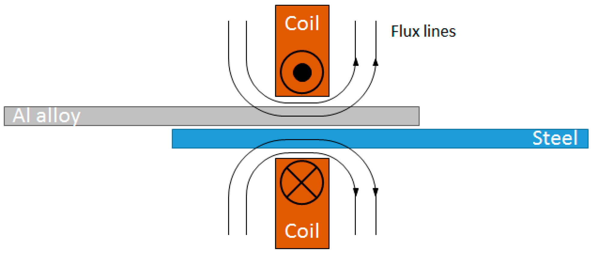
3.3. Magnetic Pulse Welding

In the magnetic pulse welding process, metallic bonding is also obtained by the collision of a flyer metal sheet on a parent metal sheet, as in explosion welding, but the flyer is accelerated by the magnetic field resulting from a pulsed current passing through a coil (Figure 12). Compared to explosion welding, this technique is more amenable to the car industry, because different welding geometries can be achieved by using special coils and tools, and because it does not require the use of hazardous materials.
A pressure exceeding the yield stress of the flyer material must be achieved in the process. This pressure is ultimately reliant on eddy currents in the flyer, and thus, on its electrical conductivity. The impact pressure is primarily influenced by the frequency of the system, the electrical conductivity and magnetic permeability of the flyer, as well as the initial proximity of the flyer to the coil, and the electric current density in the coil.
A wavy interface with few IMCs is created and joint strengths nearing or equal to those of the base material can be achieved. The most common application is welding of circular symmetrical structures such as tube-flange joints, due to the high inner field concentration inside closed circular coils. Recent developments have revealed the possibility of flat sheet lap welding using the outer field of a flat coil on the flyer sheet side and a rigid backing on the parent sheet side. In particular, Aizawa [70,71], Watanabe et al. [72], and Manogaran et al. [73] have shown that seam lap welding and spot lap welding of metal sheets are also possible. Several multi-material joint combinations that are relevant for the automotive industry have been successfully joined using magnetic pulse welding. For example, Watanabe et al. [72] and Lee et al. [74] fabricated Fe/Al joints.
The initial gap between the two sheets is important for the development of the welding interface. For example, Aizawa [70] found that without a gap, pre-cleaned surfaces and twice the electrical energy was needed. Manogaran et al. [73] proposed to pre-form the parts to-be-welded so that there is a gap between them, in order to avoid the need for costly positioning equipment or spacers between the two sheets.
The coil must both realize the appropriate magnetic field and undergo the reaction force that arises on the coil itself during the process (opposite to the force acting on the flyer plate). Various coil designs have been proposed; for example, Aizawa [70] used H-shaped flat coils, whereas Kore et al. [75] used tapered coils; more recently, Thibaudeau and Kinsey [76] developed more complex electromagnetic actuators which are capable of achieving a more uniform impact pressure.

3.4. Roll Bonding

Roll-bonding is a well-known solid-state joining method which involves high pressures in order to fabricate a bimetallic sheet. Aluminum coated steel is widely used in automotive application since offers high corrosion resistance properties of the aluminum coat combined to high mechanical properties of the steel substrate.
Several authors [77,78,79,80,81] have proposed the following mechanism. During cold rolling, the large plastic deformations that both metal sheets undergo cause the formation of micro-cracks in their brittle surface layers (which consist of strain hardened material, due to prior surface brushing, and/or of oxides). Through these cracks, virgin metals are extruded from the underneath sheets and come into direct contact, allowing the formation of atomic metallic bonds. Thickness reduction is an important factor to estimate the good joint formation, since by increasing the plastic deformation, a higher number of cracks are formed, improving the metal-to-metal contact. According to Akramifard et al. [79] and to Danesh Manesh et al. [81], the minimum thickness reduction to achieve a suitable joint is 10%.
Annealing is commonly applied after roll bonding (mainly for improving the ductility after cold rolling), but the heat treatment temperature must not be too high; otherwise brittle IMCs can be formed at the interface, decreasing the adhesion of the strips. Movahedi et al. [78] found that the joint strength increases after the annealing treatment, up to 450 °C, and proposed that this may be due to improved ductility of both metals and to atomic interdiffusion. However, the same authors, as well as Akramifard et al. [79], also found that if the annealing temperature is 500 °C or more, IMCs are formed and the joint strength decreases.
The roll bonding process is strongly restricted regarding the possible thickness combinations, because it requires a very large deformation of the original sheets for adequate joining. Therefore, roll bonding is used to produce thinner sheets than explosion welding. For this reason, cold-rolled transition joints can be used as interlayer for spot welding applications (see chapter 2.4). In contrast, they cannot normally be used as transition joints (see chapter 3.2), since the two ensuing welding lines would be too close to the original junction.
Some producers, such as Wickeder Westfalenstahl GmbH (Wickeder, Germany), can fabricate roll-bonded strips with a side-to-side geometry. In these strips, the left and right sides consist entirely of aluminum and steel, respectively, whereas the central portion consists of alternate layers of the two metals. Dissimilar roll bonding occurs only in the central portion of the strip, on the steel/aluminum interfaces parallel to the strip plane. Secondary welding operations can therefore be performed on the two sides at an adequate distance from the bimetallic interfaces. This approach, however, has not been used in industrial application, nor demonstrated in the scientific literature as yet.
Nezhad and Ardakani [77] found that warm rolling (at 150–400 °C) not only increases the bond strength, but also lowers the minimum plastic strain (or thickness reduction) that is needed for bonding. Therefore, warm rolling makes it possible to manufacture thicker sheets.
A laser-assisted roll-bonding process was developed by Pircher et al. [82], in which the faying surface is heated by a laser beam immediately before roll bonding, achieving a suitable bond with a smaller deformation, and thus, making it possible to fabricate thicker bimetallic strips.
A similar process was more recently developed by the Fraunhofer Institute for Material and Beam Technology (Bremen, Germany), for manufacturing bi-metal strips. In this process, first, steel and aluminum alloy wires are roll formed to obtain a square cross section. Thereafter, the roll-formed wires are joined by roll bonding assisted by both laser and induction heating, yielding a thick bimetal strip with a rectangular cross section. Finally, the latter strip is rotated by 90° around its axis (in respect to the prior roll bonding operation) and cold rolled, yielding a wide and thin strip, with steel on one side and aluminum on the other. These bi-metal strips have been used, at the laboratory level, as transition joints to fabricate steel-aluminum TWBs with good formability [83].

3.5. Friction Stir Welding

Friction stir welding uses a rotating tool, which consists of a pin that penetrates into the material, and of a shoulder, which is in contact with the material surface. Heat is generated by friction and plastic deformation, and solid state welding is achieved by the combination of heat and pressure. Both lap welding (Figure 13) and butt welding are possible. Moreover, the tool can be translated to form a continuous seam weld (conventional friction stir welding), or can be applied in a small region to form a spot weld (friction stir spot welding). This process was invented in 1991 by Thomas et al. [84] and, as reported in a comprehensive review by Mishra and Ma [85], has undergone continual improvements ever since. It is now widespread, especially for aluminum alloys, including several applications in the automotive industry for similar alloy couples.
Friction stir welding, as well as friction stir spot welding, for the aforementioned reasons (i.e., very limited IMC formation due to solid state welding) can be particularly effective for dissimilar joints, and has been widely investigated for Fe/Al couples.
If bare steel is friction stir welded to aluminum, IMCs can be almost completely avoided. Kimapong and Watanabe [86] and Watanabe et al. [87] reported that IMCs were formed only in a limited region close to the tool shoulder. Similarly, Tanaka et al. [88] found that a very thin layer (less than 0.3 µm thick) could also be formed in some circumstances. In contrast, it is far more challenging to weld aluminum to zinc-coated steels owing to the low melting point eutectic reaction between zinc and aluminum.
Hybrid joints produced by friction stir welding have also already been introduced in the automotive industry on some rare occasions. In 2006, the Mazda Motor Corporation introduced friction stir welding process in the production in order to join galvanized steel studs to the aluminum inner-trunk panel [89]. Six years later, Honda Motor Co. Ltd. used overlap friction stir welding of aluminum to steel in the front subframe of the Accord model. This application, in which aluminum is positioned as the top and steel as the bottom layer, was reported by Kusuda et al. [1] and Ohhama et al. [2].
Friction stir spot welding is similar to friction stir welding, except that the tool either is not translated, or it is translated over a small region only, in order to create a pointwise joint. Connoly [90] reported that homologous friction stir spot welding has been successfully applied for joining aluminum sheets in the car industry, even if the cycle time is quite slow (3–5 s).
Several approaches have been reported for friction stir spot welding aluminum to steel. Liyanage et al. [91] used a conventional tool penetrating the bottom steel sheet. Miyagawa et al. [92] used a tool that only penetrates the softer Al top sheet. Dong et al. [93] used the refill technique, employing a two-part tool with a separate sleeve and pin that can refill the hole left by the probe. Finally, Chen et al. [94] investigated the “abrasion circle” technique, in which the tool is translated through a circular path.

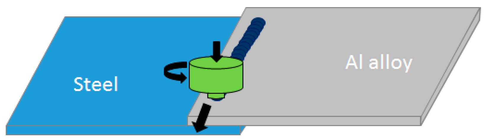
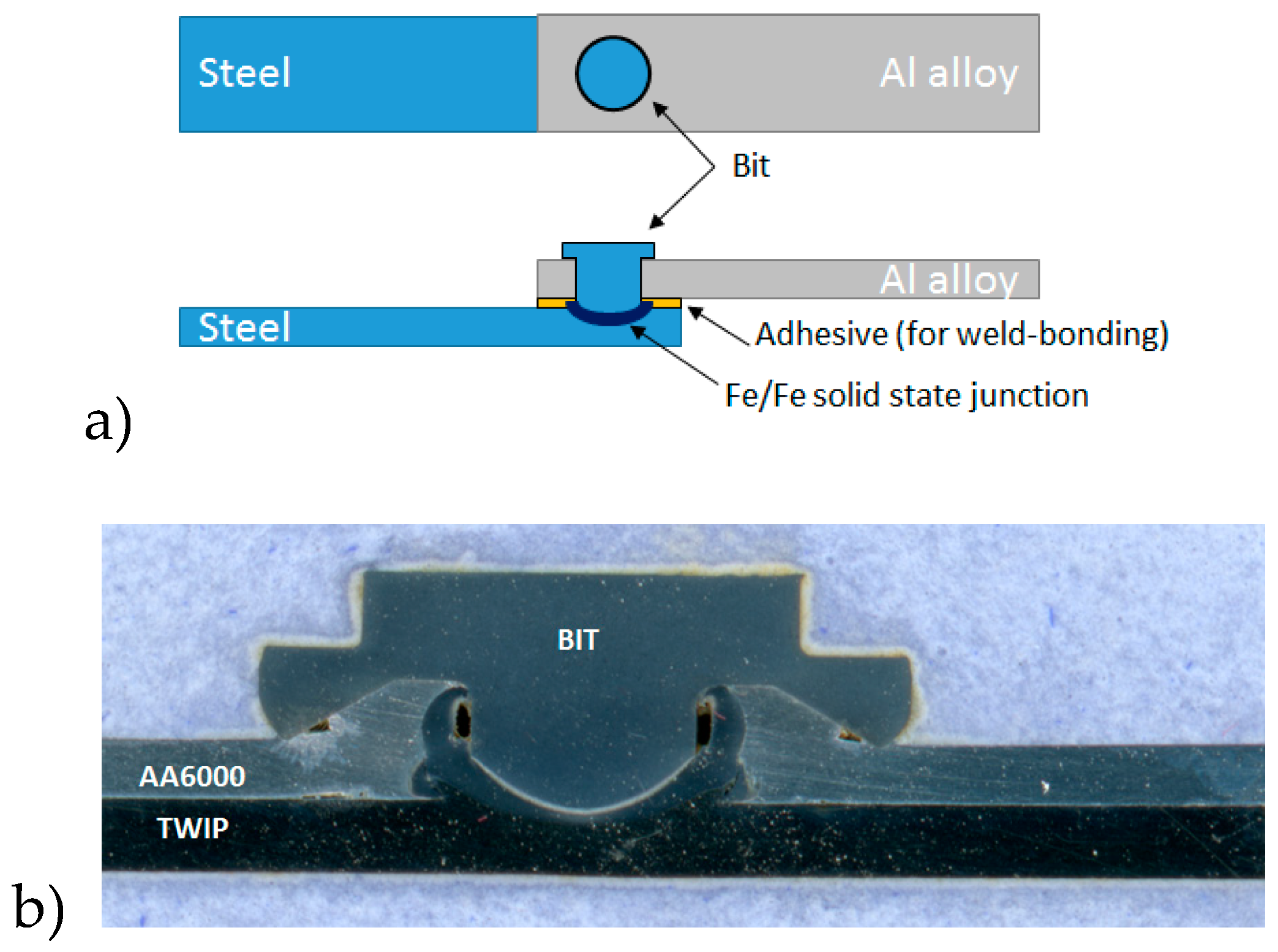
3.6. Friction Bit Joining

A new method, also based on solid state welding, is called Friction Bit Joining (FBJ) or Friction Element Welding (FEW); it involves a consumable bit as the junction material between aluminum and steel sheet (Figure 14). This method is presently used in the automotive sector in a few cases; in particular, Alber [95] reported that it is used for some components the of Audi A4 and Audi A8 car models.
The FBJ method employs two main stages: the first consists of cutting and penetrating the top material, i.e., the aluminum alloy sheet, using a rotating bit under axial load. During the second stage, the bit rotation speed is increased in order to enhance the heat between the bit and the steel layer underneath. The junction is achieved by the effect of the friction and the plastic deformation of the bit over the steel layer [96], i.e., by friction welding. Similarly to the case of the resistance element welding (see above, chapter 2.5), the steel sheet is welded to the steel rivet, whereas the aluminum sheet is mechanically joined. In the FBJ case, however, the deformation of the aluminum side also contributes to the mechanical interlock.
Squires et al. [97] reported that by using a steel bit, it is possible to achieve more than twice the lap shear fracture stress of self-piercing riveting (SPR). In addition, Alber [95] showed that FBJ is one of the few methods that allows the joining of aluminum with high-strength steel such as 22MnB4.
The joining bits are made with medium-carbon or tool steel, with hardness between 20 and 50 HRC, sufficient to cut the aluminum layer. For example, one research group, at the Young University, Utah, USA, used either the 4140 medium carbon, low-alloy steel grade [97,98,99,100], or the D2 tool steel grade [96].
The joint strength is a function of process parameters, e.g., bit hardness, rotation speed, penetration speed, and bit design. Zebisch and Mielisch [101] patented a special bit design. Miles et al. [99], by using another bit design, achieved an average lap shear of 6.5 kN, after process optimization, between 1.8 mm thick AA 5754-O and 1,4 mm thick DP 980.
This method, like other spot welding and riveting technologies, can also be used with the addition of epoxy-based thermoplastic adhesives as sealants materials. This leads to better mechanical properties and corrosion resistance than the same junction without adhesive materials. Squires et al. [97] found that the lap shear stress can increase by 50% if a 300 µm thick adhesive layer is applied; the adhesive was applied before FBJ and cured afterward. Lim et al. [100,102] reported that weld-bonded specimens show better corrosion resistance than FBJ only specimens, maintaining more than 80% of the original lap shear stress after a whole corrosion cycle. In corrosive environments, the galvanic corrosion affects mainly the bit/steel interfacial contact rather than the steel/aluminum contact, causing interfacial failure. The presence of the sealant material allows the protection of the bit/steel interface, decreasing the chance of interfacial failure.

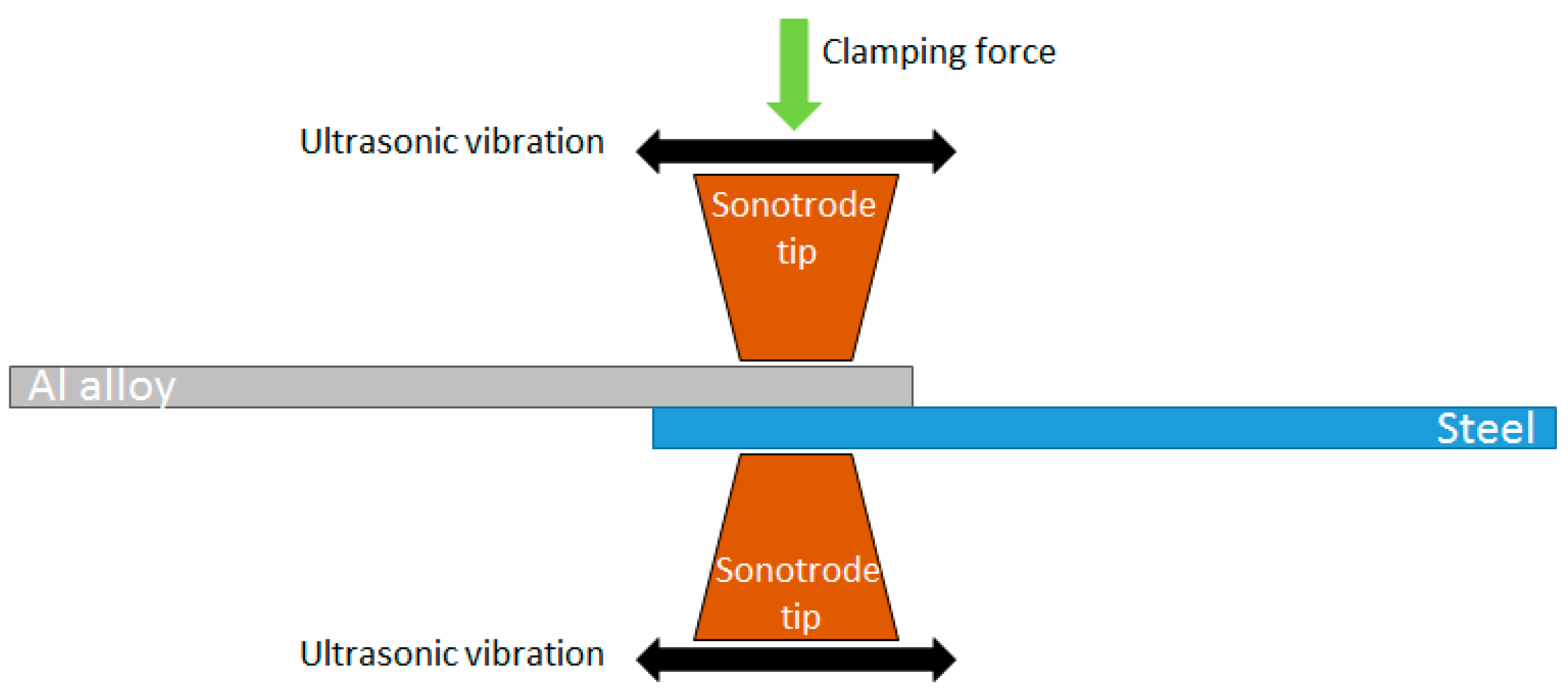
3.7. Ultrasonic Spot Welding

Ultrasonic spot welding (USW, Figure 15) is a solid-state welding process developed and used since 1950. It involves a translation motion between opposite metal sheets, which creates local deformation and heat generation sufficient to bonding. For example, Daniels et al. [103] applied this method to weld microelectronic components.
A high frequency generator supplies electrical energy that is converted by a piezoelectric transductor into mechanical vibration of the same frequency. These vibrations pass through two sonotrode tips and, as reported by Gould [104], can act on the metal sheets in two way. The first mode is called “push-pull” and the vibrations are developed by the linear oscillations that occur on the same axis of action. The second mode is called “torsional” and involves torsional movement of the sonotrodes in order to allow the junction formation. Regarding frequency, Chen et al. [105] reported that 20 kHz are effective for joining aluminum to aluminum. Moreover, several authors, [106,107,108,109] found that the same frequency is also effective for the steel-aluminum joints.
Special sonotrode tips have been developed both for the steel side and the aluminum side. In particular, Bakavos and Prangnell [106] and Prangnell et al. [110] proposed flat serrated tips for the aluminum side and dome-shaped tips for the steel side.
The workpieces are kept in contact by a clamping force that presses them between the tips. Shakil et al. [111] found that the joint strength increases by increasing the clamping pressure, but high force values require a high power energy supply. Zhao et al. [109], by applying a clamping pressure equal to 0.3 MPa, found that the influences of other parameters like process time and the wave amplitude are negligible.
Bakavos and Prangnell [106] were able to weld aluminum pieces between them in 0.3 s with a peak temperature of about 380 °C. In contrast, Watanabe et al. [112] and Prangnell et al. [110] reported that welding steel and aluminum requires more time, from 1 to 3 s, reaching temperature higher than 500 °C. Since this is the threshold temperature of IMCs formation, Prangnell et al. [110], as well as Patel et al. [113], observed the embrittlement of the welded interface due to such phenomenon. Furthermore, by using zinc-coated steel, Patel et al. [113] and Haddadi [107] observed that the reaction between aluminum and zinc can lead to the formation of an eutectic Al-Zn film, that ultimately decreases the tensile strength.

4. Discussion and Conclusion

A comparison of the mechanical properties of the hybrid joints obtained between aluminum alloy and steel sheets by using different techniques is presented in Table 1, Table 2 and Table 3 hereafter. Whenever different process parameters were tested in the same study, only the optimal combination is here reported.
This comparison is presented separately for spot, lap and butt welding. All the presented results are concerned with joints made between low carbon steel sheets with thicknesses in the range of 0.6 to 2.5 mm and 5000 or 6000 series aluminum alloy sheets with thicknesses in the range of 0.9 to 2.5 mm. The presence or absence of a zinc coating on the tested steel sheets before welding is also reported in Table 1, Table 2 and Table 3.
The results of the spot-joining methods are reported in Table 1, where the quasi-static tensile shear force is given together with the spot nugget diameter and the thickness of the IMC layer (if available), for each examined technique and materials couple. Concerning the resistance element welding and friction bit joining techniques, the rivet or bit diameter is given instead of the weld nugget diameter. The interlayer, cover plate, bit or rivet, if any, is also reported.
The tensile shear force achieved with the different methods varies between about 2 and 8 kN; however, if the same force is normalized against the thickness of the aluminum sheet, results become closer, i.e., between 1,8 and 4,7 kN/mm.
In the resistance spot welding methods, the thickness of the IMC interlayer is generally less than 5 µm and the tensile shear force is in the range of 4 to 8 kN.
The greatest tensile shear force was obtained by Resistance Spot Welding (RSW) by using a bimetallic (roll bonded) interlayer, even if the IMC layer was somewhat thicker than in plain RSW. If a roll-bonded interlayer is used, the IMC layer is probably less harmful because the steel/aluminum alloy interface (originally obtained by roll bonding) is larger than the spot itself, and presumably free from IMC outside of the spot region.
Conversely, the other modified RSW methods, i.e., the process tape and cover plate techniques, did not achieve significantly better results than plain (optimized) resistance spot welding, at least in terms of the tensile shear force. (It must be noted, however, than the reported cover plate test was performed with a smaller aluminum sheet thickness than most other RSW tests.)
The tensile shear force values achieved by using the two solid state spot welding methods, i.e., ultrasonic spot welding and friction stir spot welding, were generally somewhat lower than those achieved by plain resistance spot welding (even if in some friction stir spot welded joints the IMC layer was much thinner or not detectable). This difference may be due to the smaller thickness of the aluminum sheets used in the available literature experiments; if the tensile shear force is divided by the sheet thickness, the results are comparable.
Finally, the resistance element welding and friction bit joining processes achieve a significantly larger tensile shear force than most RSW processes (and all solid state processes). These techniques are different from all others in the fact that the welded joint is homologous (between the steel sheet and a steel rivet or bit) and the aluminum/steel joint is, in fact, a mechanical interconnection. As a consequence, the aluminum sheet thickness and base-metal strength are, in this case, the main determinants of the overall tensile shear force. (A metallurgical bond between steel and aluminum can also occur in some regions on the side of the rivet or bit, but it is much less important than the mechanical interlocking.)
Similarly, the results of continuous (linear) welding methods are reported in Table 2 and Table 3. All lap welded joints reported in Table 2 are fillet welds at the end of the aluminum alloy sheet except the friction stir welded joint, which is a seam weld; in all cases, the torch, laser source, or tool was on the aluminum alloy side. A filler was used in most cases for both lap and butt welds, and is also reported in Table 2 or Table 3; aluminum alloy fillers with the 5% or 12% Si were the more common choice.
The quasi-static tensile shear stress or tensile strength normal to the welding line is given for each lap or butt welding method in Table 2 or Table 3, respectively. The tensile shear stress or tensile strength is here calculated as the fracture force divided by the initial cross section of the aluminum side. The tensile shear stress or tensile strength was comprised between 100 and 200 MPa in the vast majority of cases, with a few values up to 250 MPa (for 6000-series aluminum alloys only).
The above defined tensile shear stress or tensile strength is also given in the Table 2 and Table 3 as a percentage of the ultimate tensile strength of the Al-alloy base metal, whenever the latter was reported. This percentage can be regarded as a measure of the efficiency of the welding process (with the only exception of the case examined by Basak et al. [118], and reported Table 2, row 4, in which the aluminum side was stronger than the steel side). On this basis, it can be concluded that a tensile shear stress or tensile strength close to 2/3 of the ultimate tensile strength of the Al alloy base metal can be achieved in most cases with the examined dissimilar welding technologies.
In the lap welding tests (Table 2), an IMC layer was always detected (between the steel side and either the filler or the aluminum alloy), but it was less than 5 µm thick in almost all cases. A somewhat thicker IMC layer was obtained in two cases (up to 12–14 µm), together with a higher-bound tensile shear strength; both effects may be due to a higher heat input per unit length.
In the butt welding experiments (Table 3), the IMC layer was generally thicker than in the lap welding one, and comprised in the 5 to 10 µm range in most cases. A thicker IMC layer during butt welding probably stems from the greater heat input used with lap welding, which is needed to ensure full thickness penetration.
Overall, the above results show that an IMC layer less than 10 µm thick is formed in most cases, and it is not especially detrimental for quasi-static loading.
The deployment of the here discussed hybrid welding technologies in the car sector is subject to two main known risks: i) that the hybrid components may not be adequate for some relevant corrosive environments; and ii) that the joining technologies themselves may not be viable or may be too expensive for large scale manufacturing.
The corrosion risk in turn arises from three facts. First, most of the technological research and development, which has been published so far, was focused on the joining technique themselves and on their mechanical performance, rather than on their corrosion performance. Second, some welding technologies can induce the formation of various phases and compounds in the joint, whose combined corrosion behavior is not well known. Third, corrosion depends on the specific environment, and in most cases no test data are available for the specific technologies and car-related environments.
However, hybrid components could be used in a large set of different automotive applications which are characterized by different corrosive environments, ranging in severity from intermediate (e.g., the door) to mild (e.g., the seat structure). Thus, it is expected that applications can be found also for those technologies that exhibit limited corrosion resistance.
The second risk, i.e., that some innovative hybrid welding technologies could be either not amenable to large-scale manufacturing, or could be too expensive, is inherent in this type of innovation. However, the structure of the car market may allow niche applications in premium and low volume cars, even for those joining technologies (if any) that will yield a high product performance, but will be expensive or difficult to perform, and therefore not suitable for mid-range cars.

Funding

This research was funded by Fiat Chrysler Automobiles N.V. within the framework of a joint research program between the same company and the Politecnico di Torino (Turin Technical University). The APC was funded by the Politecnico di Torino, DISAT department.

Conflicts of Interest

The authors declare no conflict of interest.

References

  1. Kusuda, Y. Honda develops robotized FSW technology to weld steel and aluminum and applied it to a mass-production vehicle. Ind. Rob. Int. J. 2013, 40, 208–212. [Google Scholar] [CrossRef]
  2. Ohhama, S.; Hata, T.; Yahaba, T.; Kobayashi, T.; Miyahara, T.; Sayama, M. Application of an FSW Continuous Welding Technology for Steel and Aluminum to an Automotive Subframe; SAE Tech. Paper No. 2013-01-0372; SAE International: Warrendale, PA, USA, 2013. [Google Scholar]
  3. Huland, S.; Moller, M.; Franke, M.; Vakalopoulos, T. The electrification of the Passat, the GTE. Viavision. July 2015. Available online: http://www.viavision.org.uk/ftp/1794.pdf (accessed on 6 March 2019).
  4. New Technology Saves Weight in Composite Structures; Arnold Umformtechnik GmbH & Co. KG: Forchtenberg-Ernsbach, Germany, 2017; Available online: www.arnold-fastening.com (accessed on 6 March 2019).
  5. Barnes, T.A.; Pashby, I.R. Joining techniques for aluminium spaceframes used in automobiles: Part II—Adhesive bonding and mechanical fasteners. J. Mater. Process. Technol. 2000, 99, 72–79. [Google Scholar] [CrossRef]
  6. Groche, P.; Wohletz, S.; Brenneis, M.; Pabst, C.; Resch, F. Joining by forming—A review on joint mechanisms, applications and future trends. J. Mater. Process. Technol. 2014, 214, 1972–1994. [Google Scholar] [CrossRef]
  7. He, X. A review of finite element analysis of adhesively bonded joints. Int. J. Adhes. Adhes. 2011, 31, 248–264. [Google Scholar] [CrossRef]
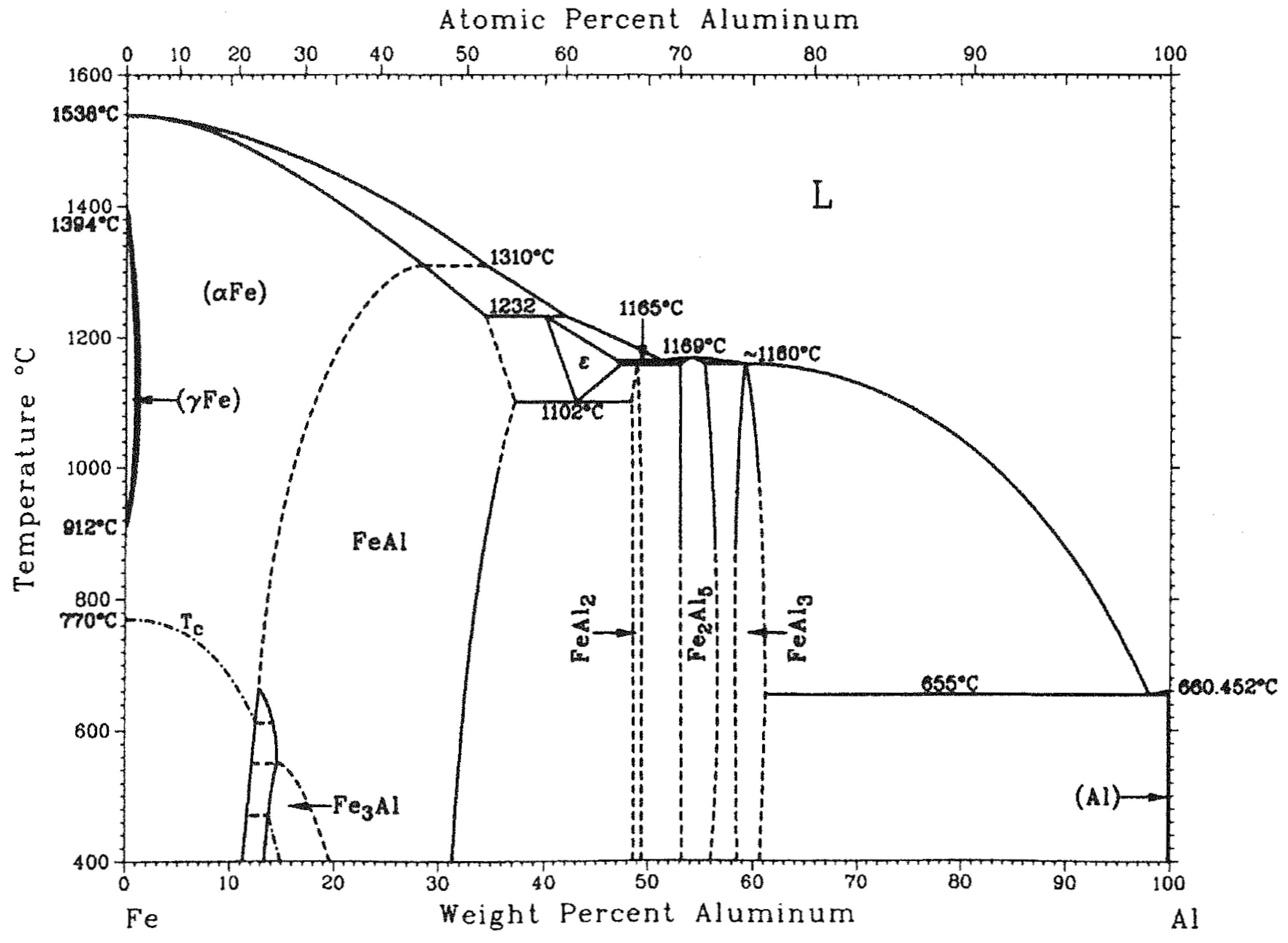
  8. Okamoto, H.; Schlesinger, E.; Mueller, E.M. (Eds.) ASM Handbook, Vol. 3, Alloy Phase Diagrams; ASM Int.: Materials Park, OH, USA, 2016. [Google Scholar]
  9. Dong, H.; Hu, W.; Duan, Y.; Wang, X.; Dong, C. Dissimilar metal joining of aluminum alloy to galvanized steel with Al–Si, Al–Cu, Al–Si–Cu and Zn–Al filler wires. J. Mater. Process. Technol. 2012, 212, 458–464. [Google Scholar] [CrossRef]
  10. Su, Y.; Hua, X.; Wu, Y. Influence of alloy elements on microstructure and mechanical property of aluminum–steel lap joint made by gas metal arc welding. J. Mater. Process. Technol. 2014, 214, 750–755. [Google Scholar] [CrossRef]
  11. Milani, A.M.; Paidar, M.; Khodabandeh, A.; Nategh, S. Influence of filler wire and wire feed speed on metallurgical and mechanical properties of MIG welding–brazing of automotive galvanized steel/5754 aluminum alloy in a lap joint configuration. Int. J. Adv. Manuf. Technol. 2016, 82, 1495–1506. [Google Scholar] [CrossRef]
  12. Sundman, B.; Ohnuma, I.; Dupin, N.; Kattner, U.R.; Fries, S.G. An assessment of the entire Al–Fe system including D03 ordering. Acta Mater. 2009, 57, 2896–2908. [Google Scholar] [CrossRef]
  13. Kouadri-David, A.; PSM Team. Study of metallurgic and mechanical properties of laser welded heterogeneous joints between DP600 galvanised steel and aluminium 6082. Mater. Des. 2014, 54, 184–195. [Google Scholar] [CrossRef]
  14. Meco, S.; Pardal, G.; Ganguly, S.; Williams, S.; McPherson, N. Application of laser in seam welding of dissimilar steel to aluminium joints for thick structural components. Opt. Lasers Eng. 2015, 67, 22–30. [Google Scholar] [CrossRef] [Green Version]
  15. Aslanlar, S.; Ogur, A.; Ozsarac, U.; Ilhan, E. Welding time effect on mechanical properties of automotive sheets in electrical resistance spot welding. Mater. Des. 2008, 29, 1427–1431. [Google Scholar] [CrossRef]
  16. Zhang, W.; Sun, D.; Han, L.; Gao, W.; Qiu, X. Characterization of intermetallic compounds in dissimilar material resistance spot welded joint of high strength steel and aluminum alloy. ISIJ Int. 2011, 51, 1870–1877. [Google Scholar] [CrossRef]
  17. Yang, D.; Sigler, D.R.; Carlson, B.E.; Schroth, J.G.; Karagoulis, M.J. Electrode for Resistance Spot Welding of Dissimilar Materials. U.S. Patent Application No. 14/181,020, 14 February 2014. [Google Scholar]
  18. Sigler, D.R.; Carlson, B.E.; Karagoulis, M.J. Resistance Spot Welding Steel and Aluminum Workpieces Using Electrode Weld Face Cover. U.S. Patent Application No. 14/462,655, 19 August 2014. [Google Scholar]
  19. Sigler, D.R.; Carlson, B.E.; Myasnikowa, Y.; Karagoulis, M.J. Multistep Direct Welding of an Aluminum Based Workpiece to a Steel Workpiece. U.S. Patent Application No. 14/464,476, 20 August 2014. [Google Scholar]
  20. GM prepping industry-first steel-to-aluminum welding process. Automotive Engineering, 19 May 2016.
  21. Kim, J.S.; Kim, I.J.; Kim, Y.G. Optimization of welding current waveform for dissimilar material with DP590 and Al5052 by Delta-spot welding process. J. Mech. Sci. Technol. 2016, 30, 2713–2721. [Google Scholar] [CrossRef]
  22. Che, Y.; Wang, L.; Sun, D.; Li, H.; Geng, W. Microstructures and mechanical properties of resistance spot-welded steel/aluminum alloy joints with process tapes. J. Mater. Eng. Perform. 2018, 27, 5532–5544. [Google Scholar]
  23. Qiu, R.; Iwamoto, C.; Satonaka, S. Interfacial microstructure and strength of steel/aluminum alloy joints welded by resistance spot welding with cover plate. J. Mater. Process. Technol. 2009, 209, 4186–4193. [Google Scholar] [CrossRef]
  24. Qiu, R.; Satonaka, S.; Iwamoto, C. Effect of interfacial reaction layer continuity on the tensile strength of resistance spot welded joints between aluminum alloy and steels. Mater. Des. 2009, 30, 3686–3689. [Google Scholar] [CrossRef]
  25. Zhang, W.; Sun, D.; Han, L.; Liu, D. Interfacial microstructure and mechanical property of resistance spot welded joint of high strength steel and aluminium alloy with 4047 AlSi12 interlayer. Mater. Des. 2014, 57, 186–194. [Google Scholar] [CrossRef]
  26. Ibrahim, I.; Ito, R.; Kakiuchi, T.; Uematsu, Y.; Yun, K.; Matsuda, C. Fatigue behaviour of Al/steel dissimilar resistance spot welds fabricated using Al–Mg interlayer. Sci. Technol. Weld. Join. 2016, 21, 223–233. [Google Scholar] [CrossRef]
  27. Haynes, G.; Jha, B. Joining aluminum to steel with transition material. SAE Technical Paper, 1 March 1999; No. 1999-01-0660. [Google Scholar]
  28. Haynes, G.; Haynes, M.; Jha, B. Applications for Clad Metals in the Automotive Industry; SAE Technical Paper, No. 2000-01-0312; SAE International: Warrendale, PA, USA, 2000. [Google Scholar]
  29. Oikawa, H.; Ohmiya, S.; Yoshimura, T.; Saitoh, T. Resistance spot welding of steel and aluminium sheet using insert metal sheet. Sci. Technol. Weld. Join. 1999, 4, 80–88. [Google Scholar] [CrossRef]
  30. Sun, X.; Stephens, E.V.; Khaleel, M.A.; Shao, H.; Kimchi, M. Resistance spot welding of aluminum alloy to steel with transition material-from process to performance—Part I: Experimental study. Weld. J. 2004, 83, 188-S. [Google Scholar]
  31. Baboian, R.; Haynes, G. Corrosion Resistance of Aluminum-Transition-Steel Joints for Automobiles; SAE Technical Paper, No. 932353; SAE International: Warrendale, PA, USA, 1993. [Google Scholar]
  32. Meschut, G.; Janzen, V.; Olfermann, T. Innovative and highly productive joining technologies for multi-material lightweight car body structures. J. Mater. Eng. Perform. 2014, 23, 1515–1523. [Google Scholar]
  33. Meschut, G.; Matzke, M.; Hoerhold, R.; Olfermann, T. Hybrid technologies for joining ultra-high-strength boron steels with aluminum alloys for lightweight car body structures. Procedia Cirp 2014, 23, 19–23. [Google Scholar] [CrossRef]
  34. Ling, Z.; Li, Y.; Luo, Z.; Feng, Y.; Wang, Z. Resistance element welding of 6061 aluminum alloy to uncoated 22MnMoB boron steel. Mater. Manuf. Process. 2016, 31, 2174–2180. [Google Scholar] [CrossRef]
  35. Ling, Z.; Li, Y.; Luo, Z.; Ao, S.; Yin, Z.; Gu, Y.; Chen, Q. Microstructure and fatigue behavior of resistance element welded dissimilar joints of DP780 dual-phase steel to 6061-T6 aluminum alloy. Int. J. Adv. Manuf. Technol. 2017, 92, 1923–1931. [Google Scholar] [CrossRef]
  36. Ready, J.F.; Farson, D.F.; Feeley, T. (Eds.) LIA Handbook of Laser Materials Processing; Springer: New York, NY, USA, 2001. [Google Scholar]
  37. Zaeh, M.F.; Moesl, J.; Musiol, J.; Oefele, F. Material processing with remote technology—Revolution or evolution? Phys. Procedia 2010, 5, 19–33. [Google Scholar] [CrossRef]
  38. Sierra, G.; Peyre, P.; Deschaux-Beaume, F.; Stuart, D.; Fras, G. Steel to aluminium key-hole laser welding. Mater. Sci. Eng. A 2007, 447, 197–208. [Google Scholar] [CrossRef]
  39. Yan, S.; Hong, Z.; Watanabe, T.; Jingguo, T. CW/PW dual-beam YAG laser welding of steel/aluminum alloy sheets. Opt. Lasers Eng. 2010, 48, 732–736. [Google Scholar] [CrossRef]
  40. Torkamany, M.J.; Tahamtan, S.; Sabbaghzadeh, J. Dissimilar welding of carbon steel to 5754 aluminum alloy by Nd: YAG pulsed laser. Mater. Des. 2010, 31, 458–465. [Google Scholar]
  41. Fan, J.; Thomy, C.; Vollertsen, F. Effect of thermal cycle on the formation of intermetallic compounds in laser welding of aluminum-steel overlap joints. Phys. Procedia 2011, 12, 134–141. [Google Scholar] [CrossRef]
  42. Pardal, G.; Meco, S.; Ganguly, S.; Williams, S.; Prangnell, P. Dissimilar metal laser spot joining of steel to aluminium in conduction mode. Int. J. Adv. Manuf. Technol. 2014, 73, 365–373. [Google Scholar] [CrossRef]
  43. Pardal, G.; Meco, S.; Dunn, A.; Williams, S.; Ganguly, S.; Hand, D.P.; Wlodarczyk, K.L. Laser spot welding of laser textured steel to aluminium. J. Mater. Process. Technol. 2017, 241, 24–35. [Google Scholar] [Green Version]
  44. Peyre, P.; Sierra, G.; Deschaux-Beaume, F.; Stuart, D.; Fras, G. Generation of aluminium–steel joints with laser-induced reactive wetting. Mater. Sci. Eng. A 2007, 444, 327–338. [Google Scholar]
  45. Sierra, G.; Peyre, P.; Deschaux-Beaume, F.; Stuart, D.; Fras, G. Galvanised steel to aluminium joining by laser and GTAW processes. Mater. Charact. 2008, 59, 1705–1715. [Google Scholar]
  46. Weller, D.; Simon, J.; Stritt, P.; Weber, R.; Graf, T.; Bezençon, C.; Bassi, C. Temperature controlled laser joining of aluminum to galvanized steel. Phys. Procedia 2016, 83, 515–522. [Google Scholar] [CrossRef]
  47. Sierra, G.; Peyre, P.; Deschaux-Beaume, F.; Stuart, D.; Fras, G. Steel to aluminium braze welding by laser process with Al–12Si filler wire. Sci. Technol. Weld. Join. 2008, 13, 430–437. [Google Scholar] [CrossRef]
  48. Mathieu, A.; Pontevicci, S.; Viala, J.C.; Cicala, E.; Mattei, S.; Grevey, D. Laser brazing of a steel/aluminium assembly with hot filler wire (88% Al, 12% Si). Mater. Sci. Eng. A 2006, 435, 19–28. [Google Scholar]
  49. Mathieu, A.; Shabadi, R.; Deschamps, A.; Suery, M.; Mattei, S.; Grevey, D.; Cicala, E. Dissimilar material joining using laser (aluminum to steel using zinc-based filler wire). Opt. Laser Technol. 2007, 39, 652–661. [Google Scholar]
  50. Sun, J.; Yan, Q.; Li, Z.; Huang, J. Effect of bevel angle on microstructure and mechanical property of Al/steel butt joint using laser welding-brazing method. Mater. Des. 2016, 90, 468–477. [Google Scholar]
  51. Zhang, Y.; Li, F.; Guo, G.; Wang, G.; Wei, H. Effects of different powders on the micro-gap laser welding-brazing of an aluminium-steel butt joint using a coaxial feeding method. Mater. Des. 2016, 109, 10–18. [Google Scholar]
  52. Li, L.; Xia, H.; Tan, C.; Ma, N. Effect of groove shape on laser welding-brazing Al to steel. J. Mater. Process. Technol. 2018, 252, 573–581. [Google Scholar]
  53. Li, L.; Xia, H.; Tan, C.; Ma, N. Influence of laser power on interfacial microstructure and mechanical properties of laser welded-brazed Al/steel dissimilar butted joint. J. Manuf. Process. 2018, 32, 160–174. [Google Scholar] [CrossRef]
  54. Tan, C.; Zang, C.; Xia, H.; Zhao, X.; Zhang, K.; Meng, S.; Chen, B.; Song, X.; Li, L. Influence of Al additions in Zn–based filler metals on laser welding–brazing of Al/steel. J. Manuf. Process. 2018, 34, 251–263. [Google Scholar] [CrossRef]
  55. Xia, H.; Zhao, X.; Tan, C.; Chen, B.; Song, X.; Li, L. Effect of Si content on the interfacial reactions in laser welded-brazed Al/steel dissimilar butted joint. J. Mater. Process. Technol. 2018, 258, 9–21. [Google Scholar] [CrossRef]
  56. Xia, H.; Zhang, L.; Tan, C.; Wu, L.; Chen, B.; Li, L. Effect of heat input on a laser powder deposited Al/steel butt joint. Opt. Laser Technol. 2019, 111, 459–469. [Google Scholar] [CrossRef]
  57. Zhang, H.T.; Feng, J.C.; He, P.; Hackl, H. Interfacial microstructure and mechanical properties of aluminium–zinc-coated steel joints made by a modified metal inert gas welding–brazing process. Mater. Charact. 2007, 58, 588–592. [Google Scholar] [CrossRef]
  58. Zhang, H.T.; Feng, J.C.; He, P.; Zhang, B.B.; Chen, J.M.; Wang, L. The arc characteristics and metal transfer behaviour of cold metal transfer and its use in joining aluminium to zinc-coated steel. Mater. Sci. Eng. A 2009, 499, 111–113. [Google Scholar] [CrossRef]
  59. Lin, J.; Ma, N.; Lei, Y.; Murakawa, H. Shear strength of CMT brazed lap joints between aluminum and zinc-coated steel. J. Mater. Process. Technol. 2013, 213, 1303–1310. [Google Scholar] [CrossRef]
  60. Yang, S.; Zhang, J.; Lian, J.; Lei, Y. Welding of aluminum alloy to zinc coated steel by cold metal transfer. Mater. Des. 2013, 49, 602–612. [Google Scholar] [CrossRef]
  61. Findik, F. Recent developments in explosive welding. Mater. Des. 2011, 32, 1081–1093. [Google Scholar] [CrossRef]
  62. Acarer, M.; Demir, B. An investigation of mechanical and metallurgical properties of explosive welded aluminum–dual phase steel. Mater. Lett. 2008, 62, 4158–4160. [Google Scholar] [CrossRef]
  63. Tricarico, L.; Spina, R. Experimental investigation of laser beam welding of explosion-welded steel/aluminum structural transition joints. Mater. Des. 2010, 31, 1981–1992. [Google Scholar] [CrossRef]
  64. Han, J.H.; Ahn, J.P.; Shin, M.C. Effect of interlayer thickness on shear deformation behavior of AA5083 aluminum alloy/SS41 steel plates manufactured by explosive welding. J. Mater. Sci. 2003, 38, 13–18. [Google Scholar] [CrossRef]
  65. Aceves, S.M.; Espinosa-Loza, F.; Elmer, J.W.; Huber, R. Comparison of Cu, Ti and Ta interlayer explosively fabricated aluminum to stainless steel transition joints for cryogenic pressurized hydrogen storage. Int. J. Hydrog. Energy 2015, 40, 1490–1503. [Google Scholar] [CrossRef] [Green Version]
  66. Sherpa, B.B.; Upadhyay, A.; Kumar, S.; Kumar, P.D.; Agarwal, A. Examination of Joint Integrity in parallel plate configuration of explosive welded SS-Al combination. Mater. Today Proc. 2017, 4, 1260–1267. [Google Scholar] [CrossRef]
  67. Technical Brochure; Dynamic Materials Corp.: Boulder, CO, USA, 2012.
  68. Technical Brochure; Merrem & La Porte, B.V.: Zaltbommel, The Netherlands, 2005.
  69. Nobili, D.; Gauthier, A. Specification Number NC 630a; Nobelclad Europe SA: Rivesaltes, France, 2011. [Google Scholar]
  70. Aizawa, T. Magnetic pressure seam welding method for aluminium sheets. Weld. Int. 2003, 17, 929–933. [Google Scholar] [CrossRef]
  71. Aizawa, T. Magnetic pressure seam welding method for sheet metals. J. Jpn. Inst. Light Met. 2004, 54, 153–158. [Google Scholar] [CrossRef]
  72. Watanabe, M.; Kumai, S.; Aizawa, T. Interfacial microstructure of magnetic pressure seam welded Al-Fe, Al-Ni and Al-Cu lap joints. Mater. Sci. Forum 2006, 519–521, 1145–1150. [Google Scholar] [CrossRef]
  73. Manogaran, A.P.; Manoharan, P.; Priem, D.; Marya, S.; Racineux, G. Magnetic pulse spot welding of bimetals. J. Mater. Process. Technol. 2014, 214, 1236–1244. [Google Scholar] [CrossRef]
  74. Lee, K.J.; Kumai, S.; Arai, T.; Aizawa, T. Interfacial microstructure and strength of steel/aluminum alloy lap joint fabricated by magnetic pressure seam welding. Mater. Sci. Eng. A 2007, 471, 95–101. [Google Scholar] [CrossRef]
  75. Kore, S.D.; Date, P.P.; Kulkarni, S.V. Electromagnetic impact welding of aluminum to stainless steel sheets. J. Mater. Process. Technol. 2008, 208, 486–493. [Google Scholar] [CrossRef]
  76. Thibaudeau, E.; Kinsey, B.L. Analytical design and experimental validation of uniform pressure actuator for electromagnetic forming and welding. J. Mater. Process. Technol. 2015, 215, 251–263. [Google Scholar] [CrossRef]
  77. Nezhad, M.S.A.; Ardakani, A.H. A study of joint quality of aluminum and low carbon steel strips by warm rolling. Mater. Des. 2009, 30, 1103–1109. [Google Scholar] [CrossRef]
  78. Movahedi, M.; Kokabi, A.H.; Reihani, S.S. Investigation on the bond strength of Al-1100/St-12 roll bonded sheets, optimization and characterization. Mater. Des. 2011, 32, 3143–3149. [Google Scholar] [CrossRef]
  79. Akramifard, H.R.; Mirzadeh, H.; Parsa, M.H. Cladding of aluminum on AISI 304L stainless steel by cold roll bonding: Mechanism, microstructure, and mechanical properties. Mater. Sci. Eng. A 2014, 613, 232–239. [Google Scholar] [CrossRef]
  80. Gao, C.; Li, L.; Chen, X.; Zhou, D.; Tang, C. The effect of surface preparation on the bond strength of Al-St strips in CRB process. Mater. Des. 2016, 107, 205–211. [Google Scholar] [CrossRef]
  81. Danesh Manesh, H.; Karimi Taheri, A. Study of mechanisms of cold roll welding of aluminium alloy to steel strip. Mater. Sci. Technol. 2004, 20, 1064–1068. [Google Scholar] [CrossRef]
  82. Pircher, H.; Kawalla, R.; Poprawe, R.; Sussek, G. Laser-Assisted Plating of Strip. U.S. Patent Application No. 08/875,676, 23 January 1996. [Google Scholar]
  83. Jahn, A.; Brenner, B.; Wagner, M.; Pautzsch, R.; Bellmann, J. Laser joined steel-aluminum hybrid structures. Presented at the “Materials in Car-Body Engineering” Conference, Bad Nauheim, Germany, 13–14 May 2014. [Google Scholar]
  84. Thomas, W.M.; Nicholas, E.D.; Needham, J.C.; Murch, M.G.; Temple-Smith, P.; Dawes, C.J. Friction Welding. U.S. Patent Application No. 244,612, 1 August 1994. [Google Scholar]
  85. Mishra, R.S.; Ma, Z.Y. Friction stir welding and processing. Mater. Sci. Eng. R 2005, 50, 1–78. [Google Scholar] [CrossRef]
  86. Kimapong, K.; Watanabe, T. Friction stir welding of aluminum alloy to steel. Weld. J. 2004, 83, 277. [Google Scholar]
  87. Watanabe, T.; Takayama, H.; Yanagisawa, A. Joining of aluminum alloy to steel by friction stir welding. J. Mater. Process. Technol. 2006, 178, 342–349. [Google Scholar] [CrossRef]
  88. Tanaka, T.; Morishige, T.; Hirata, T. Comprehensive analysis of joint strength for dissimilar friction stir welds of mild steel to aluminum alloys. Scr. Mater. 2009, 61, 756–759. [Google Scholar] [CrossRef]
  89. Colwell, K.C. Two metals enter, one leaves: The miracle of friction stir welding. Car and Driver, 15 May 2013. [Google Scholar]
  90. Connolly, C. Friction spot joining in aluminium car bodies. Ind. Robot Int. J. 2007, 34, 17–20. [Google Scholar] [CrossRef]
  91. Liyanage, T.; Kilbourne, J.; Gerlich, A.P.; North, T.H. Joint formation in dissimilar Al alloy/steel and Mg alloy/steel friction stir spot welds. Sci. Technol. Weld. Join. 2009, 14, 500–508. [Google Scholar] [CrossRef]
  92. Miyagawa, K.; Tsubaki, M.; Yasui, T.; Fukumoto, M. Spot welding between aluminium alloy and Zn-coated steel by friction stirring. Weld. Int. 2009, 23, 648–653. [Google Scholar] [CrossRef]
  93. Dong, H.; Chen, S.; Song, Y.; Guo, X.; Zhang, X.; Sun, Z. Refilled friction stir spot welding of aluminum alloy to galvanized steel sheets. Mater. Des. 2016, 94, 457–466. [Google Scholar] [CrossRef]
  94. Chen, Y.C.; Gholinia, A.; Prangnell, P.B. Interface structure and bonding in abrasion circle friction stir spot welding: A novel approach for rapid welding aluminium alloy to steel automotive sheet. Mater. Chem. Phys. 2012, 134, 459–463. [Google Scholar] [CrossRef]
  95. Alber, U. Friction element welding–Innovations for hybrid body parts. Presented at the "Joining in Car-Body Engineering" Conference, Bad Nauheim, Germany, 17–19 April 2012. [Google Scholar]
  96. Miles, M.; Hong, S.T.; Woodward, C.; Jeong, Y.H. Spot welding of aluminum and cast iron by friction bit joining. Int. J. Precis. Eng. Manuf. 2013, 14, 1003–1006. [Google Scholar] [CrossRef]
  97. Squires, L.; Lim, Y.C.; Miles, M.P.; Feng, Z. Mechanical properties of dissimilar metal joints composed of DP 980 steel and AA 7075-T6. Sci. Technol. Weld. Join. 2015, 20, 242–248. [Google Scholar] [CrossRef]
  98. Miles, M.P.; Kohkonen, K.; Packer, S.; Steel, R.; Siemssen, B.; Sato, Y.S. Solid state spot joining of sheet materials using consumable bit. Sci. Technol. Weld. Join. 2009, 14, 72–77. [Google Scholar] [CrossRef]
  99. Miles, M.P.; Feng, Z.; Kohkonen, K.; Weickum, B.; Steel, R.; Lev, L. Spot joining of AA 5754 and high strength steel sheets by consumable bit. Sci. Technol. Weld. Join. 2010, 15, 325–330. [Google Scholar] [CrossRef]
  100. Lim, Y.C.; Squires, L.; Pan, T.Y.; Miles, M.; Song, G.L.; Wang, Y.; Feng, Z. Study of mechanical joint strength of aluminum alloy 7075-T6 and dual phase steel 980 welded by friction bit joining and weld-bonding under corrosion medium. Mater. Des. 2015, 69, 37–43. [Google Scholar] [CrossRef] [Green Version]
  101. Zebisch, S.; Mielisch, M. Friction Welding Element. U.S. Patent Application No. 14/135,208, 19 December 2013. [Google Scholar]
  102. Lim, Y.C.; Squires, L.; Pan, T.Y.; Miles, M.; Keum, J.K.; Song, G.L.; Wang, Y.; Feng, Z. Corrosion behaviour of friction-bit-joined and weld-bonded AA7075-T6/galvannealed DP980. Sci. Technol. Weld. Join. 2017, 22, 455–464. [Google Scholar]
  103. Daniels, H.P.C.; Botden, T.Р.; Philips, N.V. Ultrasonic welding in microminiaturization. IFAC Proc. Vol. 1965, 2, 473–484. [Google Scholar] [CrossRef]
  104. Gould, J.E. Joining aluminum sheet in the automotive industry—A 30 year history. Weld. J. 2012, 91, 23s–34s. [Google Scholar]
  105. Chen, Y.C.; Bakavos, D.; Gholinia, A.; Prangnell, P.B. HAZ development and accelerated post-weld natural ageing in ultrasonic spot welding aluminium 6111-T4 automotive sheet. Acta Mater. 2012, 60, 2816–2828. [Google Scholar] [CrossRef]
  106. Bakavos, D.; Prangnell, P.B. Mechanisms of joint and microstructure formation in high power ultrasonic spot welding 6111 aluminium automotive sheet. Mater. Sci. Eng. A 2010, 527, 6320–6334. [Google Scholar] [CrossRef]
  107. Haddadi, F. Microstructure reaction control of dissimilar automotive aluminium to galvanized steel sheets ultrasonic spot welding. Mater. Sci. Eng. A 2016, 678, 72–84. [Google Scholar] [CrossRef]
  108. Haddadi, F.; Abu-Farha, F. The effect of interface reaction on vibration evolution and performance of aluminium to steel high power ultrasonic spot joints. Mater. Des. 2016, 89, 50–57. [Google Scholar] [CrossRef]
  109. Zhao, D.; Ren, D.; Zhao, K.; Pan, S.; Guo, X. Effect of welding parameters on tensile strength of ultrasonic spot welded joints of aluminum to steel—By experimentation and artificial neural network. J. Manuf. Process. 2017, 30, 63–74. [Google Scholar] [CrossRef]
  110. Prangnell, P.; Haddadi, F.; Chen, Y.C. Ultrasonic spot welding of aluminium to steel for automotive applications—Microstructure and optimisation. Mater. Sci. Technol. 2011, 27, 617–624. [Google Scholar]
  111. Shakil, M.; Tariq, N.H.; Ahmad, M.; Choudhary, M.A.; Akhter, J.I.; Babu, S.S. Effect of ultrasonic welding parameters on microstructure and mechanical properties of dissimilar joints. Mater. Des. 2014, 55, 263–273. [Google Scholar] [CrossRef]
  112. Watanabe, T.; Sakuyama, H.; Yanagisawa, A. Ultrasonic welding between mild steel sheet and Al–Mg alloy sheet. J. Mater. Process. Technol. 2009, 209, 5475–5480. [Google Scholar] [CrossRef]
  113. Patel, V.K.; Bhole, S.D.; Chen, D.L. Ultrasonic spot welding of aluminum to high-strength low-alloy steel: Microstructure, tensile and fatigue properties. Metall. Mater. Trans. A 2014, 45, 2055–2066. [Google Scholar] [CrossRef]
  114. Arghavani, M.R.; Movahedi, M.; Kokabi, A.H. Role of zinc layer in resistance spot welding of aluminium to steel. Mater. Des. 2016, 102, 106–114. [Google Scholar]
  115. Chen, N.; Wang, H.P.; Carlson, B.E.; Sigler, D.R.; Wang, M. Fracture mechanisms of Al/steel resistance spot welds in lap shear test. J. Mater. Process. Technol. 2017, 243, 347–354. [Google Scholar]
  116. Piccini, J.M.; Svoboda, H.G. Tool geometry optimization in friction stir spot welding of Al-steel joints. J. Manuf. Process. 2017, 26, 142–154. [Google Scholar] [CrossRef]
  117. Su, Y.; Hua, X.; Wu, Y. Effect of input current modes on intermetallic layer and mechanical property of aluminum–steel lap joint obtained by gas metal arc welding. Mater. Sci. Eng. A 2013, 578, 340–345. [Google Scholar] [CrossRef]
  118. Basak, S.; Das, H.; Pal, T.K.; Shome, M. Characterization of intermetallics in aluminum to zinc coated interstitial free steel joining by pulsed MIG brazing for automotive application. Mater. Charact. 2016, 112, 229–237. [Google Scholar] [CrossRef]
  119. Yagati, K.P.; Bathe, R.N.; Rajulapati, K.V.; Rao, K.B.S.; Padmanabham, G. Fluxless arc weld-brazing of aluminium alloy to steel. J. Mater. Process. Technol. 2014, 214, 2949–2959. [Google Scholar]
  120. Pouranvari, M.; Abbasi, M. Dissimilar gas tungsten arc weld-brazing of Al/steel using Al-Si filler metal: Microstructure and strengthening mechanisms. J. Alloys Compd. 2018, 749, 121–127. [Google Scholar] [CrossRef]
  121. Coelho, R.S.; Kostka, A.; Sheikhi, S.; Dos Santos, J.; Pyzalla, A.R. Microstructure and mechanical properties of an AA6181-T4 aluminium alloy to HC340LA high strength steel friction stir overlap weld. Adv. Eng. Mater. 2008, 10, 961–972. [Google Scholar]
  122. Cui, L.; Chen, B.; Qian, W.; He, D.; Chen, L. Microstructures and mechanical properties of dissimilar Al/Steel butt joints produced by autogenous laser keyhole welding. Metals 2017, 7, 492. [Google Scholar] [CrossRef]
  123. Qin, G.; Ji, Y.; Ma, H.; Ao, Z. Effect of modified flux on MIG arc brazing-fusion welding of aluminum alloy to steel butt joint. J. Mater. Process. Technol. 2017, 245, 115–121. [Google Scholar] [CrossRef]
Figure 1. Hybrid friction stir welding of the front subframe of the Honda Accor, reproduced from [2], with permission of SAE International, 2013.
Metals 09 00315 g001
Figure 2. Fe-Al phase diagram [7].
Metals 09 00315 g002
Figure 3. Resistance spot welding using a ring-shaped electrode on the aluminum alloy side: overview (a) and ring-shaped electrode (b) [17].
Metals 09 00315 g003
Figure 4. Resistance spot welding using a removable cover on the aluminum alloy side.
Metals 09 00315 g004
Figure 5. Resistance spot welding using a steel cover plate (a) and example of cover plate welding between 6016 aluminum alloy and DP1000 Steel (b).
Metals 09 00315 g005
Figure 6. (a) Schematic illustration of a bimetallic strip used as transition joint between aluminum and steel sheets. The white line on the Al alloy/steel interface evidence the IMC formation region. (b) Section of a spot weld with a bimetallic interlayer, with thickness ratio 40% Al alloy/60% steel.
Metals 09 00315 g006
Figure 7. (a) Resistance element welding. (b) Section of a resistance element welding obtained between a 6xxx series Al alloy and a TWIP steel.
Metals 09 00315 g007
Figure 8. Laser welding with the keyhole mode: general view (a) and cross-section detail of the keyhole (b).
Metals 09 00315 g008
Figure 9. Laser welding with the conduction mode: overall view (a) and cross-section of the process zone (b).
Metals 09 00315 g009
Figure 10. Joining between aluminum and steel by using a transition joint.
Metals 09 00315 g010
Figure 11. Cross section of an explosion welded joint between a steel and an aluminum alloy, with a titanium interlayer.
Metals 09 00315 g011
Figure 12. Magnetic pulse welding between steel and aluminum.
Metals 09 00315 g012
Figure 13. Friction stir welding between steel and aluminum in the lap joint case.
Metals 09 00315 g013
Figure 14. Friction bit joint configuration (a) and metallographic section of and FBJ spot (b).
Metals 09 00315 g014
Figure 15. Ultrasonic spot welding.
Metals 09 00315 g015
Table 1. Main results of hybrid spot joining methods.
MethodAl Alloy SheetSteel SheetInterlayer, Cover Plate or Bit MaterialNugget or Bit Diameter (mm)Tensile Shear Force (N)IMC th. (µm)Reference
Gradeth. (mm)Gradeth. (mm)Zn
Plain Resistance Spot Welding (RSW)50522DC011N-8.553005.5[114]
50522Low C1Y-9.365004[114]
50831.5DP9801N-740001[22]
60221.2Low C2Y-7.850002.5[115]
RSW with process tape50831.5DP9801N-9.545002.4[22]
RSW with interlayer51822SAE 10081.4NAl 0.3/steel 1.2 mm8.2–1075008.5[30]
RSW with cover plate50521SPCC (DC01)1NSPCC (1 mm)8.946802.5[23]
Resistance Element Welding6061222MnMoB1.8NSteel Q235570864[34]
60612DP7801.4NSteel Q23557368n. d.[35]
Friction Bit Joining57541.8DP9801.4NSteel 414066300n. r.[98]
57541.8DP5901.6NSteel 41406.56400n. r.[99]
Ultrasonic Spot welding61111DX 56-Z1Y--270010[107]
61111DX 53-ZF1Y--320015[107]
60611A361.5N-103919n. r.[109]
61110.93DC041N--28001.8[110]
57541.5HSLA0.8Y--3700n. r.[113]
Friction Stir Spot Welding61111DC041N-83500n. d.[94]
61111.15Low C1.8Y--2070n. r.[91]
50521Low C0.65N--2700< 5[116]
n. r.: not reported or not investigated. n. d.: investigated, but not detected.
Table 2. Main results of hybrid continuous (linear) lap welding methods.
MethodAl SheetSteel SheetsFillerTensile Shear StressIMC th. (µm)Ref.
Gradeth. (mm)UTS (MPa)Gradeth. (mm)Zn(MPa)(%)
MIG-CMT Arc welding60612235DP6001.2YAlSi510444N. A.[59]
60612n. r.Low C1.2YAlSi5133n. a.<5[60]
50521n. r.mild steel1YAlSi12201n. a.2–3[117]
MIG Arc welding60612295IF1YAlSi5122416.1–14[118]
57543n. r.Low C2YAlSi3Mn188n. a.5.4[11]
60612n. r.IF Steel1.2YAlSi5111n. a.1.5–3.5[119]
TIG Arc welding5A022n. r.Q2351.5YAlSi12136n. a.2[9]
60612n. r.DQSK1.5YAlSi5103n. a.2–4[120]
Laser welding60161260DC041.2NAlSi1219073<2[47]
60161260DC041.2Y-2509612[45]
64511230Low C0.8Y-146635[46]
Friction Stir Welding61811.5n. r.HC340LA1.5N-230n. a.0.2[121]
n. r.: not reported. n. a.: not available.
Table 3. Main results of hybrid continuous (linear) butt welding methods.
MethodAl SheetSteel SheetFillerTensile StrengthIMC th. (µm)Ref.
Gradeth. (mm)UTS (MPa)Gradeth. (mm)Zn(MPa)(%)
Laser welding60612.5n. r.Q2352.5YAlSi5150n. a.8.3[50]
525111900.1% C, 5% Mn1NAlSi12128674[51]
60612310DP5902NAlSi10Mg1946310[56]
50836n. r.Q2356N-110n. a.>10[122]
60611.5310DP5901.2NZnAl22274888.4–13[54]
60611.5310DP5901.2NAlSi5208673.8–7.5[55]
60612310DP5902NAlSi12140454.9–8.6[52,53]
MIG50521.5n. r.Low C1.2YAlSi5120n. a.>2[123]
n. r.: not reported. n. a.: not available.

