Article

Effect of Forced Air Cooling on the Microstructures, Tensile Strength, and Hardness Distribution of Dissimilar Friction Stir Welded AA5A06-AA6061 Joints

1
College of Mechanical Engineering, Zhejiang University of Technology, Hangzhou 310014, China
2
Key Laboratory of E&M (Zhejiang University of Technology), Ministry of Education & Zhejiang Province, Hangzhou 310014, China
3
State Key Laboratory for Geomechanics and Deep Underground Engineering, School of Mechanics and Civil Engineering, China University of Mining and Technology, Xuzhou 221116, China
4
Department of Mechanical and Aerospace Engineering, The George Washington University, Washington, DC 20052, USA
5
Institute of Solid Mechanics, Beihang University, Beijing 100191, China
*
Authors to whom correspondence should be addressed.
Metals 2019, 9(3), 304; https://doi.org/10.3390/met9030304
Submission received: 29 January 2019 / Revised: 22 February 2019 / Accepted: 4 March 2019 / Published: 7 March 2019
(This article belongs to the Special Issue Characterization of Welded Joints)

Abstract

:
Friction stir welding (FSW) is a promising welding method for welding dissimilar materials without using welding flux. In the present work, 5A06-H112 and 6061-T651 aluminium alloys were successfully welded by friction stir welding with forced air cooling (FAC) and natural cooling (NC). Nanoindentation tests and microstructure characterisations revealed that forced air cooling, which can accelerate the cooling process and suppress the coarsening of grains and the dissolution of precipitate phases, contributes to strengthening and narrowing the weakest area of the joint. The tensile strength of joints with FAC were commonly improved by 10% compared to those with NC. Scanning electron microscopy (SEM) images of the fracture surface elucidated that FSW with FAC tended to increase the number and reduce the size of the dimples. These results demonstrated the advantages of FSW with FAC in welding heat-sensitive materials and provide fresh insight into welding industries.

1. Introduction

Aluminium alloys have been widely used in the aviation, aerospace, shipping, and transportation industries because of their advantages of high specific strength, good fatigue performance, and strong corrosion resistance [1,2,3]. However, the welding of aluminium alloys presents great challenges. Traditional welding methods are not suitable for aluminium alloys, particularly dissimilar aluminium alloys, since they are prone to generate defects such as porosity and crack during solidification [4,5]. Friction stir welding (FSW)—which is a cost-effective and environmentally friendly solid-state method developed by the Welding Institute in 1991 [6]—is a promising welding method that avoids the above-mentioned issues. According to the microstructures and thermal effect, FSW joints can be typically divided into four zones: nugget zone (NZ), thermo-mechanical affected zone (TMAZ), heat affected zone (HAZ), and base material (BM).
Several researchers have investigated the friction stir welding of aluminium alloys and found that FSW could significantly improve the strength of welded joints compared with traditional welding methods [7,8,9,10,11,12,13]. However, due to the large amount of heat generated by friction and plastic deformation, the welded joint shows an obvious thermal softening effect, leading to the strength of the HAZ being lower than the BM [14,15]. Taking this into account, a forced cooling medium was applied during the welding process to reduce the thermal softening and improve the strength of the joint. Zhang et al. [16] pointed out that the tensile strength and corrosion resistance of FSW AA2014 joints were enhanced via water cooling. Sharma et al. [17] studied the effects of air, water, and liquid nitrogen cooling on AA7039 FSW, and suggested that water cooling was more helpful in improving the mechanical properties of the joints. Benavides et al. [18] investigated the mechanical properties of FSW AA2024 joints cooled by liquid nitrogen, and revealed that (1) the grain size in the NZ reduced, (2) the softening area of the joint narrowed, and (3) the hardness of the TMAZ and HAZ increased. Heirani et al. [19] focused on the influence of underwater FSW on the microstructure and mechanical properties of AA5083. They found that the HAZ of the joint disappeared, and the strength and hardness were improved. Other studies also indicated that a forced cooling medium is beneficial for improving the mechanical performances of FSW aluminium alloy joints [20,21,22,23].
The 5A06 is a corrosion-resistant non-heat treatable aluminium alloy (Al-Mg alloy), while 6061 is a high-strength heat-treatable aluminium alloy (Al-Mg-Si alloy) [24]. In the present work, a forced air cooling system that is cheap and easy to use was added to the commercial friction stir welding machine. The main purpose was to understand the effect of forced air cooling on the microstructure and mechanical properties of FSW AA5A06-AA6061 joints. The microstructures, tensile properties, hardness distribution, and fracture features of the joints welded in different conditions were systematically investigated and discussed.

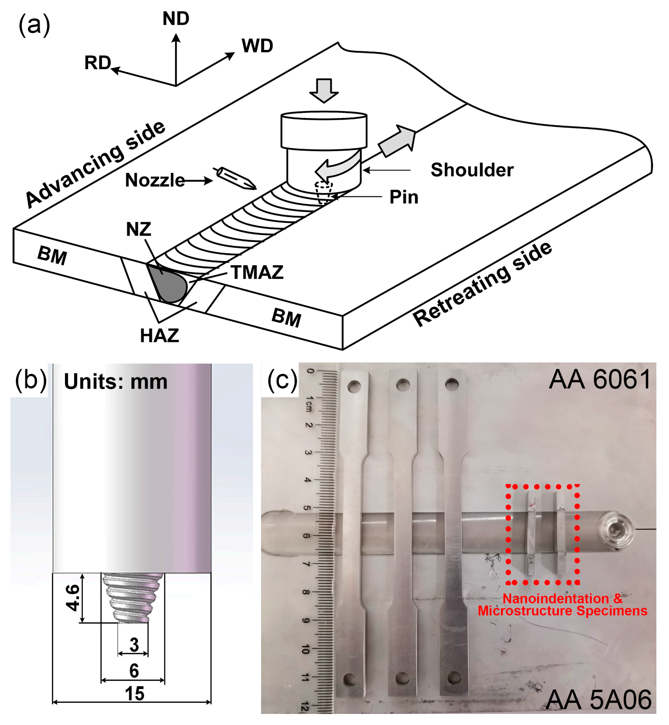
2. Materials and Methods

Rolled AA5A06-H112 and AA6061-T651 plates with a thickness of 5 mm were employed as base materials, and the chemical compositions obtained by energy dispersive spectroscopy (EDS, Carl Zeiss SMT Pte Ltd., Oberkochen, Germany) are listed in Table 1. The plates were cut into small rectangular plates measuring 165 mm × 5 mm. These rectangular plates were welded in butt joint configuration using FSW by placing AA5A06 on the advancing side and AA6061 on the retreating side. A welding machine HT-JL10X12/2H (Shanghai Aerospace Equipments Manufacturer Co., Ltd., Shanghai, China) with a forced air cooling system was employed to carry out FSW. Both natural cooling (NC) and forced air cooling (FAC) conditions were considered in the FSW process. For FAC, forced air was blown on the welded area through a nozzle, as shown in Figure 1a. The rectangular nozzle with a size of 10 mm × 2 mm was placed 20 mm behind the tool and about 20 mm above the surface of the materials. The pressure of the forced air was 0.5 MPa, and the blowing direction was along the welding direction and had an intersection angle of 30° with the surface of the materials. The tapered left-hand threaded cylindrical tool used for FSW was made of “H13 steel”, and the dimensions are shown in Figure 1b. During the welding process, the tool was plunged into the butt surface of the two base materials, with a tilt angle of 2.8° and a depth of 4.96 mm. Three different tool rotational speeds (RS)—i.e., 600, 900, and 1200 rpm—and two welding transverse speeds (TS)—i.e., 100 and 200 mm/min—were applied. It has been reported that the left-hand thread pin tool rotating clockwise generates better FSW joints [25]. Thus, a clockwise rotation direction of the tool was used in the experiments. As shown in Figure 1c, the welded AA5A06-AA6061 plates were processed into dumbbell-shaped specimens for uniaxial tensile tests and small rectangular specimens for nanoindentation and microstructure characterisation.
For microstructure characterisation, the side surface of the specimen was polished to a mirror finish using an automatic polishing machine (Shenyang Kejing Auto-instrument Co. Ltd., Shenyang, China) with 0.3 μm alumina powder. The surfaces were anodic coated and then observed using a polarizing microscope (Carl Zeiss AG Co. Ltd., Guangzhou, China). To obtain the hardness distribution in the joint area, nanoindentation tests were implemented in an Agilent Nano Indenter G200 system with a modified Berkovich indenter (Agilent Technologies, Oak Ridge, TN, USA). The nanoindentation hardness mapping method was used and an array consisting of 56 × 10 indents was carried out on the side surface of each specimen, as shown in Figure 1c. For each nanoindentation test, the maximum indentation load was 120 mN, and the thermal drift was controlled within 0.05 nm/s.
For uniaxial tensile tests, the dumbbell-shaped specimens had 1 mm of thickness machined away from both the top and bottom surface to ensure they had a uniform cross section. A material testing system, MTS CMT4204 (MTS System Co. Ltd., Shanghai, China) was employed to conduct the tensile tests. All the specimens were stretched to break at a tensile strain rate of about 0.04 s−1 at room temperature. The average value of the ultimate tensile strength was used for analysis. Scanning electron microscopy (SEM, Carl Zeiss SMT Pte Ltd., Oberkochen, Germany) was employed to analyse the microstructures of the fracture surface.

3. Results and Discussion

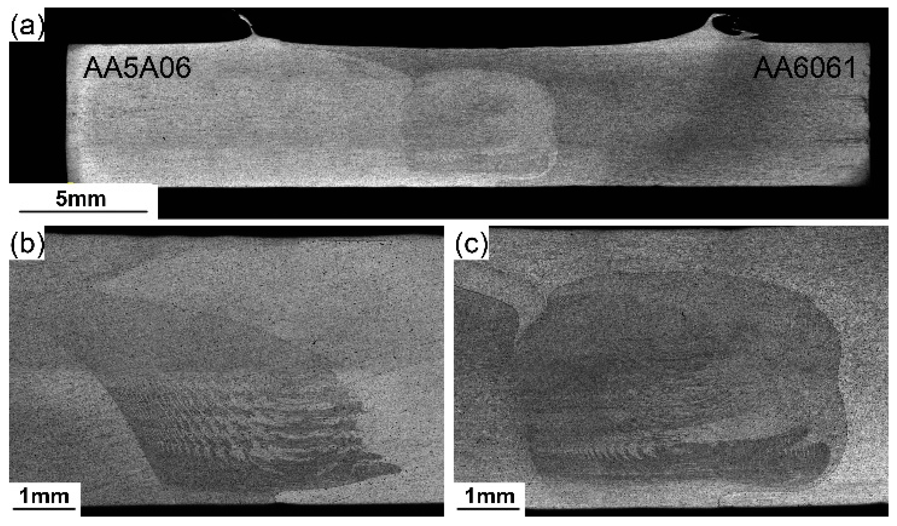
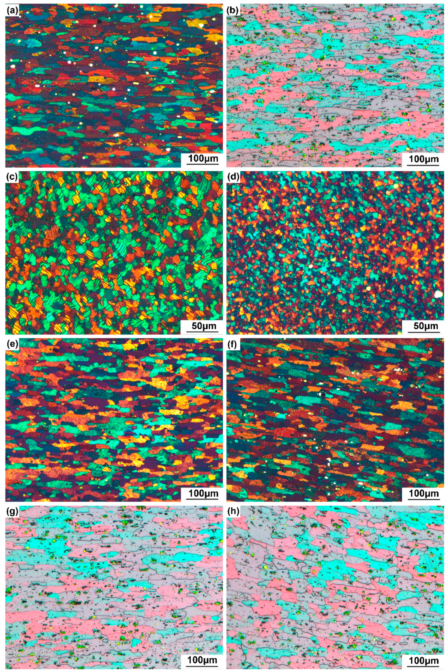
3.1. Microstructures

Defect-free joints were obtained for all welding parameters and conditions. Figure 2a shows a representative cross section of the joint, obtained at the ratio of rotational speed to transverse speed (R/T ratio) of 1200/100 r/mm with FAC. As shown in Figure 2, “onion rings” and interlaced ripple structures, which indicate a good mixing of materials, were observed in the NZ. The formation of an “onion ring” is attributed to the thermal softening of the materials, and the stirring action, extrusion, and transverse movement of the threaded tool [26]. Comparison of the “onion rings” in Figure 2b,c revealed that the spacing between the ripples decreases with an increase in the rotational speed of the tool, which agrees with Rodriguez’s report [27]. There are two main reasons for this: (1) the higher heat input generated by the higher rotational speed makes the materials softer and easier to flow under mechanical stirring, and (2) higher rotational speed provides a higher stirring force, which mixes these two materials sufficiently to form narrower ripples.
Figure 3 shows typical microstructures of different regions of the FSW AA5A06-AA6061 joints welded at a rotational speed of 1200 rpm and a welding speed of 100 mm/min with NC and FAC. Rolled prolate grains were observed in the BM of both AA5A06 and AA6061, and their average grain size was 49 μm and 50 μm, respectively (Figure 3a,b). For both cooling conditions, the NZ exhibits dynamically recrystallised microstructures with fine equiaxed grains (Figure 3c,d), which are the result of thermal softening and large plastic deformation during the FSW process. The average grain sizes in the NZ were 14 μm and 8 μm for FSW with NC and FAC, respectively. Figure 3e,f shows the grain structures of the HAZ of the 5A06 side for FSW with NC and FAC, and their average grain sizes, which were 52 μm and 51 μm, respectively. It was found that the average grain size in the HAZ and the BM of AA5A06 were almost the same and independent of the cooling conditions. The reason for this was that AA5A06 is a non-heat treatable aluminium alloy, and the heat generated by the FSW had little effect on the grain structures. On the 6061 side, however, the average grain size of the HAZ for FSW with NC is 57 μm (Figure 3g), an increase of about 14% compared to the average grain size of the BM. This was due to the fact that AA6061 is a heat-treatable alloy, and is therefore sensitive to temperature variations. The elevated temperature generated during the FSW process induced the growing and coarsening of grains in the HAZ. With the aid of the FAC, the average grain size of the HAZ on the 6061 side was reduced to 53 μm (Figure 3h). The FSW with FAC treatment could accelerate the cooling process and reduce the affecting time of high temperatures, thus suppressing the coarsening and growth of the grains.

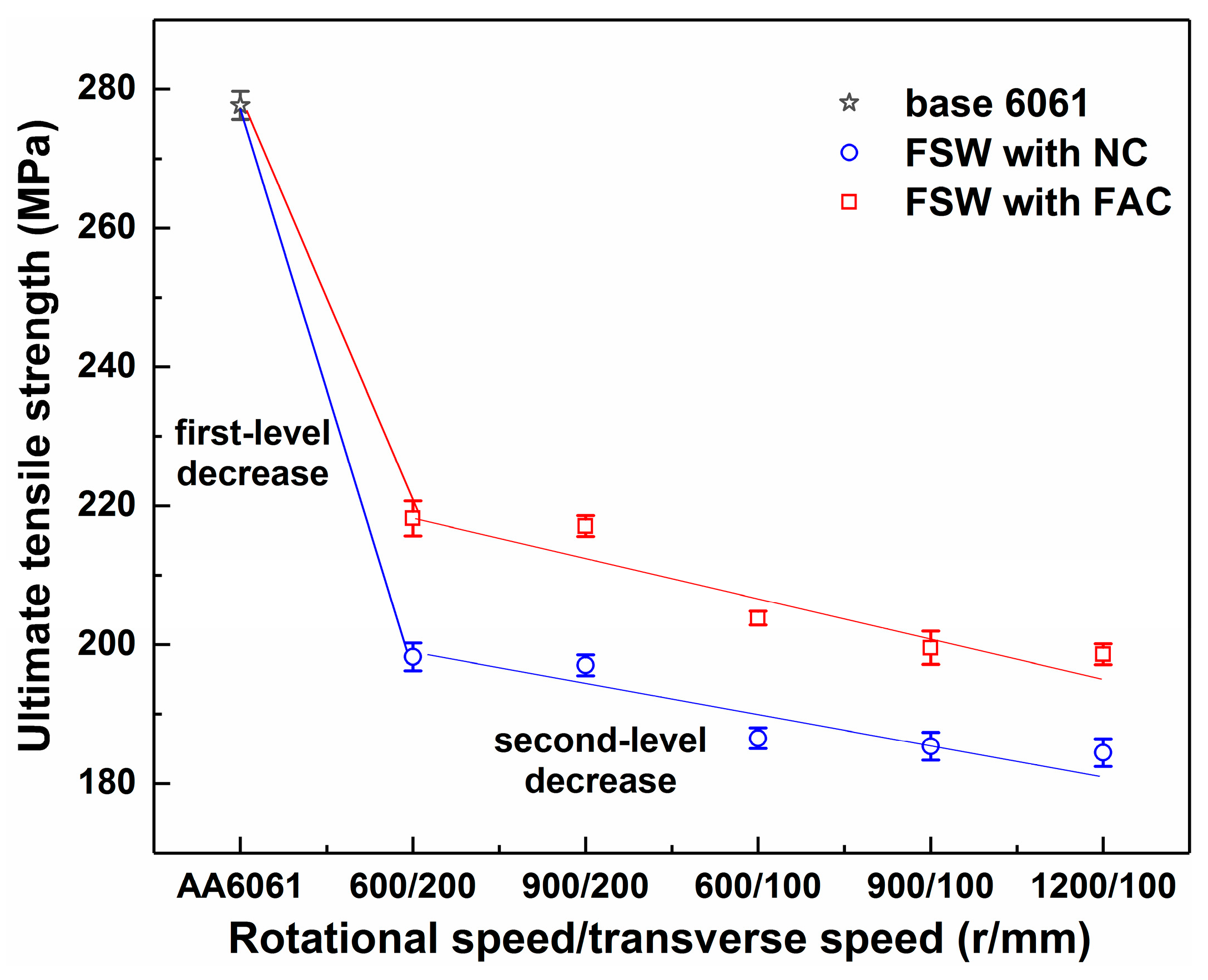
3.2. Uniaxial Tensile Properties

After the uniaxial tensile tests, it was found that the fracture occurred at the HAZ of the AA6061 side for all the FSW joints. This means that the ultimate tensile strength of AA6061 was weakened after welding, and the HAZ on the AA6061 side became the weakest area. Figure 4 shows the ultimate tensile strength of the base AA6061 and the FSW joints welded at various R/T ratios and under different cooling conditions. For FSW with NC, the joint welded at an R/T ratio of 600/200 r/mm had the maximum ultimate tensile strength of 198.27 MPa, which was 29% lower than that of the base AA6061. As the R/T ratio increased from 3 (600/200) r/mm to 12 (1200/100) r/mm, the ultimate tensile strength continued to decrease slowly, and the decrease was within 10%. It is evident from Figure 4 that there were two levels of decrease for the tensile strength of the FSW joints.
For the first-level decrease, the tensile strength of the FSW joint was largely weakened once the AA6061 was friction stir welded. As Peel et al. [28] pointed out, this is because the rolled AA6061 was kept in an extremely work-hardened state and had highly unstable microstructures. The recrystallisation caused by the temperature rising during FSW can readily destroy the hardened state and significantly weaken the mechanical properties. In addition, precipitation hardening is one of the strengthening mechanisms for heat-treatable AA6061 [29,30], and grain size also plays an important role according to the Hall-Petch relationship [31]. For AA6061, the main strengthening phase is the needle-shaped β″ phase. With the increase of the heat input, the fine needle-shaped β″ phase dissolved and grew to the coarsened rod-shaped β′ phase and equilibrium β phase, which weakened the mechanical properties of the joint [32,33]. A comparison of Figure 3b,g reveals that the grains became coarser after welding. To sum up, the first-level decrease in tensile strength was attributed to the destruction of the hardened state (the primary reason), the dissolution and coarsening of the strengthening phases, and the coarsening of the grains. For the second-level decrease, the tensile strength of the FSW joint was slightly weakened with the increase of the R/T ratio. This was mainly because the higher R/T ratio generated a higher temperature, which led to more strengthening phases to be coarsened and causing grains to grow larger. The further dissolution of the precipitates and further coarsening of the grains could weaken the tensile strength with the increase of the R/T ratio, as shown in Figure 4.
With the aid of FAC, the cooling process was accelerated, and the affecting time of the high temperature was reduced. This was conducive to suppressing the coarsening of the grains and the dissolution of the precipitates in the HAZ of 6061, and thus improved the mechanical properties. As shown in Figure 4, the ultimate tensile strength of the joints with FAC was commonly improved by 10% compared to that with NC.

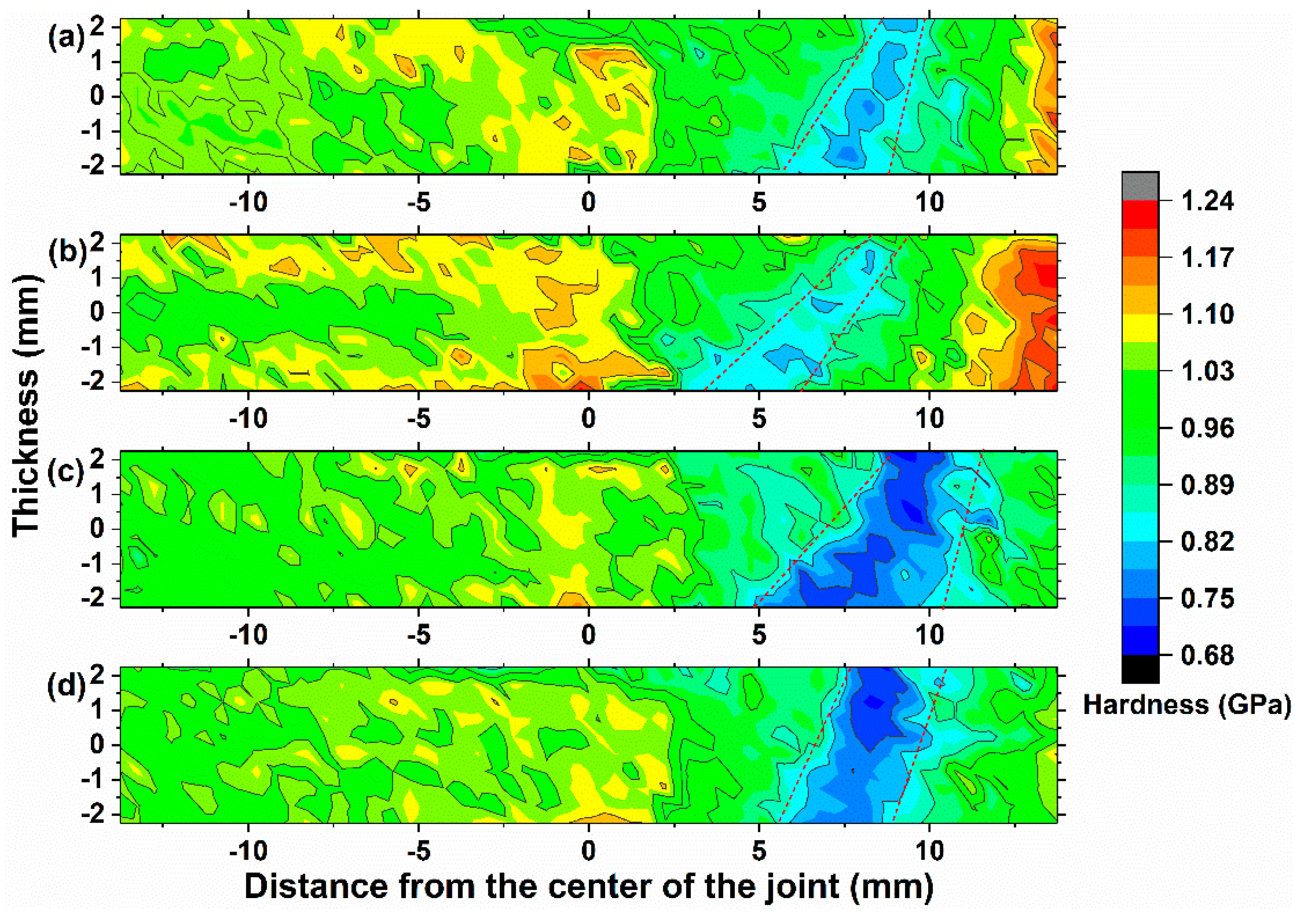
3.3. Nanoindentation Hardness Distribution

The nanoindentation hardness distribution on the cross-section of the FSW joints is shown in Figure 5. The hardness distribution on the AA5A06 side varied slightly for all the welding parameters. The maximum hardness appeared near the NZ and TMAZ, which was similar to the FSW AA5182 reported by Tronci et al. [31,34]. The reason for this was that AA5A06 is a non-heat treatable alloy, and therefore the temperature variation does not significantly affect the hardness. Near the NZ and TMAZ, the hardness was partially improved due to the refinement of the grains as a result of the stirring action. For the AA6061 side, a dramatic drop in hardness was observed in the HAZ due to the coarsening of the grains and the dissolution of the precipitates [35]. The HAZ of AA 6061 became the weakest area in the FSW joint. This intuitively explains why the fracture occurred in the HAZ of AA6061 during tensile tests. A comparison of Figure 5a,b or Figure 5c,d reveals that the hardness in the HAZ of AA6061 was improved and the weakest area was narrowed with the help of FAC. This is consistent with the results observed in the tensile test, namely that the strength was improved via FAC. The FSW with FAC could reduce the affecting time of high temperatures and suppress the coarsening of the grains and the dissolution of the precipitate phases in the HAZ of 6061, contributing to the improvement of the joint hardness.

3.4. Fracture Characteristics

Figure 6 shows the SEM images of the microstructures of the fracture surfaces. The dimples are observed in all fracture surfaces, indicating the ductile fracture mechanism of the joints. For FSW with NC, the fracture surface of the joint obtained at an R/T ratio of 1200/100 r/mm exhibited large and deep dimples (Figure 6a). When the R/T ratio reduced to 600/200 r/mm, the dimples became smaller (Figure 6b). For the fracture surfaces of the FSW joints with FAC, as shown in Figure 6c,d, the dimples continue to become smaller and shallower. It is understood that the size of the dimple is affected by the spacing of the precipitates, and a larger dimple leads to better plasticity and worse strength [36]. The quantity and size of the dimples can indirectly reflect the number and size of the precipitates. As mentioned above, precipitation hardening is the main strengthening mechanism for AA 6061. Typically, smaller and more uniformly distributed precipitates lead to better mechanical properties. Based on this point of view, it could be inferred from Figure 6 that the strength of joints with FAC is commonly higher than that of naturally cooled joints, which coincides well with the uniaxial tensile results.

4. Conclusions

The 5A06 and 6061 aluminium alloys were successfully friction stir welded in both NC and FAC conditions. For all the welded joints, the HAZ of AA6061 was the weakest area and fracture occurred in this region during tensile tests. There were two levels of decrease in the tensile strength of the FSW joints. For the first-level decrease, the tensile strength of the FSW joint was largely weakened due to the destruction of the hardened state (the primary reason), the dissolution of the precipitates and the coarsening of the grains. For the second-level decrease, the tensile strength of the FSW joint was slightly weakened with the increase of the R/T ratio. This is attributed to the further dissolution of the precipitates and further coarsening of the grains, caused by the increase in temperature during FSW. FAC can effectively accelerate the cooling process and reduce the affecting time of high temperature during FSW, suppressing the coarsening of the grains and the dissolution of the precipitates in HAZ of 6061, as well as generally improve the ultimate tensile strength by 10% compared with NC. The nanoindentation hardness contour maps also intuitively illustrate that FSW with forced air cooling is conducive to improving the hardness in the HAZ of AA 6061 and narrowing the weakest area.

Author Contributions

Funding acquisition, G.P. and T.Z.; Investigation, G.P., Q.Y., J.H., P.C. and Z.C.; Methodology, J.H. and P.C.; Supervision, G.P. and T.Z.; Writing—original draft, Q.Y.; Writing—review and editing, G.P. and Z.C.

Funding

The authors would like to gratefully acknowledge the support of the National Natural Science Foundation of China (Grant Nos. 11772302, 11727803 and 11672356) and Zhejiang Province Public Welfare Technology Application Research Project (2015C31074).

Conflicts of Interest

The authors declare no conflict of interest.

References

  1. Dursun, T.; Soutis, C. Recent developments in advanced aircraft aluminium alloys. Mater. Des. 2014, 56, 862–871. [Google Scholar] [CrossRef]
  2. Gharavi, F.; Matori, K.A.; Yunus, R.; Othman, N.K.; Fadaeifard, F. Corrosion Evaluation of Friction Stir Welded Lap Joints of AA6061-T6 Aluminum Alloy. Trans. Nonferr. Metals Soc. Chin. 2016, 26, 672–681. [Google Scholar] [CrossRef]
  3. Hassan, K.A.A.; Prangnell, P.B.; Norman, A.F.; Price, D.A.; Williams, S.W. Effect of welding parameters on nugget zone microstructure and properties in high strength aluminium alloy friction stir welds. Sci. Technol. Weld. Join. 2003, 8, 257–268. [Google Scholar] [CrossRef]
  4. Biradar, N.S. Investigation of hot cracking behavior in transverse mechanically arc oscillated autogenous AA2014 T6 TIG welds. Metall. Mater. Trans. A 2012, 43, 3179–3191. [Google Scholar] [CrossRef]
  5. Ericsson, M.; Sandström, R. Influence of welding speed on the fatigue of friction stir welds, and comparison with MIG and TIG. Int. J. Fatigue 2003, 25, 1379–1387. [Google Scholar] [CrossRef]
  6. Threadgill, P.L.; Leonard, A.J.; Shercliff, H.R.; Withers, P.J. Friction stir welding of aluminium alloys. Metall. Rev. 2009, 54, 49–93. [Google Scholar] [CrossRef]
  7. Elangovan, K.; Balasubramanian, V.; Babu, S. Predicting tensile strength of friction stir welded AA6061 aluminium alloy joints by a mathematical model. Mater. Des. 2009, 30, 188–193. [Google Scholar] [CrossRef]
  8. Kalemba-Rec, I.; Kopyscianski, M.; Miara, D.; Krasnowski, K. Effect of process parameters on mechanical properties of friction stir welded dissimilar 7075-T651 and 5083-H111 aluminum alloys. Int. J. Adv. Manuf. Technol. 2018, 97, 2767–2779. [Google Scholar] [CrossRef]
  9. Rafiei, R.; Shamanian, M.; Fathi, M.H.; Khodabakhshi, F. Dissimilar friction-stir lap-welding of aluminum-magnesium (AA5052) and aluminum-copper (AA2024) alloys: Microstructural evolution and mechanical properties. Int. J. Adv. Manuf. Technol. 2018, 94, 3713–3730. [Google Scholar] [CrossRef]
  10. Tamadon, A.; Pons, D.J.; Sued, K.; Clucas, D. Thermomechanical Grain Refinement in AA6082-T6 Thin Plates under Bobbin Friction Stir Welding. Met.-Basel 2018, 8. [Google Scholar] [CrossRef]
  11. Zeng, X.H.; Xue, P.; Wang, D.; Ni, D.R.; Xiao, B.L.; Ma, Z.Y. Realising equal strength welding to parent metal in precipitation-hardened Al-Mg-Si alloy via low heat input friction stir welding. Sci. Technol. Weld. Join. 2018, 23, 478–486. [Google Scholar] [CrossRef]
  12. Zeng, X.H.; Xue, P.; Wang, D.; Ni, D.R.; Xiao, B.L.; Wang, K.S.; Ma, Z.Y. Material flow and void defect formation in friction stir welding of aluminium alloys. Sci. Technol. Weld. Join. 2018, 23, 677–686. [Google Scholar] [CrossRef]
  13. Zhang, Q.; Lang, L.; Zhang, Y.; Sun, G. Application of the modified critical voids expansion ratio criterion to the prediction of the forming limit of 6016-O aluminum alloy. Int. J. Adv. Manuf. Technol. 2018, 98, 2069–2082. [Google Scholar] [CrossRef]
  14. Fratini, L.; Buffa, G.; Shivpuri, R. In-process heat treatments to improve FS-welded butt joints. Int. J. Adv. Manuf. Technol. 2009, 43, 664–670. [Google Scholar] [CrossRef]
  15. Peng, G.; Ma, Y.; Hu, J.; Jiang, W.; Huan, Y.; Chen, Z.; Zhang, T. Nanoindentation Hardness Distribution and Strain Field and Fracture Evolution in Dissimilar Friction Stir-Welded AA 6061-AA 5A06 Aluminum Alloy Joints. Adv. Mater. Sci. Eng. 2018, 2018, 1–11. [Google Scholar] [CrossRef]
  16. Zhang, Z.; Xiao, B.L.; Ma, Z.Y. Influence of water cooling on microstructure and mechanical properties of friction stir welded 2014Al-T6 joints. Mater. Sci. Eng. A 2014, 614, 6–15. [Google Scholar] [CrossRef]
  17. Sharma, C.; Dwivedi, D.K.; Kumar, P. Influence of in-process cooling on tensile behaviour of friction stir welded joints of AA7039. Mater. Sci. Eng. A 2012, 556, 479–487. [Google Scholar] [CrossRef]
  18. Benavides, S.; Li, Y.; Murr, L.E.; Brown, D.; Mcclure, J.C. Low-temperature friction-stir welding of 2024 aluminum. Scr. Mater. 1999, 41, 809–815. [Google Scholar] [CrossRef]
  19. Heirani, F.; Abbasi, A.; Ardestani, M. Effects of processing parameters on microstructure and mechanical behaviors of underwater friction stir welding of Al5083 alloy. J. Manuf. Process. 2017, 25, 77–84. [Google Scholar] [CrossRef]
  20. Zhang, H. Characteristics and formation mechanisms of welding defects in underwater friction stir welded aluminum alloy. Metall. Microst. Anal. 2012, 1, 269–281. [Google Scholar] [CrossRef]
  21. Sinhmar, S.; Dwivedi, D.K. Enhancement of mechanical properties and corrosion resistance of friction stir welded joint of AA2014 using water cooling. Mater. Sci. Eng. A 2017, 684, 413–422. [Google Scholar] [CrossRef]
  22. Sabari, S.S.; Malarvizhi, S.; Balasubramanian, V. Influences of tool traverse speed on tensile properties of air cooled and water cooled friction stir welded AA2519-T87 aluminium alloy joints. J. Mater. Process. Technol. 2016, 237, 286–300. [Google Scholar] [CrossRef]
  23. Mofid, M.A.; Abdollah-Zadeh, A.; Gür, C.H. Submerged friction-stir welding (SFSW) underwater and under liquid nitrogen: An improved method to join Al alloys to Mg alloys. Metall. Mater. Trans. A 2012, 43, 5106–5114. [Google Scholar] [CrossRef]
  24. Kim, J.R.; Ahn, E.Y.; Das, H.; Jeong, Y.H.; Hong, S.T.; Miles, M.; Lee, K.J. Effect of tool geometry and process parameters on mechanical properties of friction stir spot welded dissimilar aluminum alloys. Int. J. Precis. Eng. Man. 2017, 18, 445–452. [Google Scholar] [CrossRef]
  25. Chowdhury, S.M.; Chen, D.L.; Bhole, S.D.; Cao, X. Tensile properties of a friction stir welded magnesium alloy: Effect of pin tool thread orientation and weld pitch. Mater. Sci. Eng. A 2010, 527, 6064–6075. [Google Scholar] [CrossRef]
  26. Ouyang, J.H.; Kovacevic, R. Material flow and microstructure in the friction stir butt welds of the same and dissimilar aluminum alloys. J. Mater. Eng. Perform. 2002, 11, 51–63. [Google Scholar] [CrossRef]
  27. Rodriguez, R.I.; Jordon, J.B.; Allison, P.G.; Rushing, T.; Garcia, L. Microstructure and mechanical properties of dissimilar friction stir welding of 6061-to-7050 aluminum alloys. Mater. Des. 2015, 83, 60–65. [Google Scholar] [CrossRef]
  28. Peel, M.; Steuwer, A.; Preuss, M.; Withers, P.J. Microstructure, mechanical properties and residual stresses as a function of welding speed in aluminium AA5083 friction stir welds. Acta. Mater. 2003, 51, 4791–4801. [Google Scholar] [CrossRef]
  29. MetalsBahemmat, P.; Haghpanahi, M.; Besharati, M.K.; Ahsanizadeh, S.; Rezaei, H. Study on mechanical, micro-, and macrostructural characteristics of dissimilar friction stir welding of AA6061-T6 and AA7075-T6. Proc. Inst. Mech. Eng. B-J. Eng. 2010, 1, 1–12. [Google Scholar]
  30. Leitao, C.; Leal, R.M.; Rodrigues, D.M.; Loureiro, A.; Vilaca, P. Mechanical behaviour of similar and dissimilar AA5182-H111 and AA6016-T4 thin friction stir welds. Mater. Des. 2009, 30, 101–108. [Google Scholar] [CrossRef] [Green Version]
  31. Tronci, A.; Mckenzie, R.; Leal, R.M.; Rodrigues, D.M. Microstructural and mechanical characterisation of 5XXX-H111 friction stir welded tailored blanks. Sci. Technol. Weld. Join. 2013, 16, 433–439. [Google Scholar] [CrossRef]
  32. Lee, W.B.; Yeon, Y.M.; Jung, S.B. Mechanical Properties Related to Microstructural Variation of 6061 Al Alloy Joints by Friction Stir Welding. Mater Trans. 2004, 45, 1700–1705. [Google Scholar] [CrossRef] [Green Version]
  33. Liu, F.J.; Fu, L.; Chen, H.Y. Effect of high rotational speed on temperature distribution, microstructure evolution, and mechanical properties of friction stir welded 6061-T6 thin plate joints. Int. J. Mach. Tool. Manuf. 2018, 96, 1823–1833. [Google Scholar] [CrossRef]
  34. Leitao, C.; Emilio, B.; Chaparro, B.M.; Rodrigues, D.M. Formability of similar and dissimilar friction stir welded AA 5182-H111 and AA 6016-T4 tailored blanks. Mater. Des. 2009, 30, 3235–3242. [Google Scholar] [CrossRef] [Green Version]
  35. Netto, N.; Tiryakioglu, M.; Eason, P.D. Characterization of Microstructural Refinement and Hardness Profile Resulting from Friction Stir Processing of 6061-T6 Aluminum Alloy Extrusions. Met.-Basel 2018, 8, 552. [Google Scholar] [CrossRef]
  36. Liu, H.; Pan, Q.; Yu, L. Effect of friction stir welding parameters on microstructural characteristics and mechanical properties of 2219-T6 aluminum alloy joints. Int. J. Mater. Form. 2012, 5, 235–241. [Google Scholar] [CrossRef]
Figure 1. (a) Schematic of friction stir welding (FSW) with forced air cooling, (b) geometry of the tool, (c) specimens for uniaxial tensile tests, nanoindentation, and microstructure characterisation.
Metals 09 00304 g001
Figure 2. Macroscopic features of the joints with forced air cooling: (a) cross-section of a joint welded at a rotational speed to transverse speed (R/T) ratio of 1200/100 r/mm, (b) NZ of a joint welded at an R/T ratio of 600/100 r/mm, and (c) NZ of a joint welded at an R/T ratio of 1200/100 r/mm.
Metals 09 00304 g002
Figure 3. Microstructures of different regions of the FSW joints welded at an R/T ratio of 1200/100 r/mm with natural cooling (NC) and forced air cooling (FAC): (a) base material (BM) of 5A06, (b) BM of 6061, (c) nugget zone (NZ) (with NC), (d) NZ (with FAC), (e) heat affected zone (HAZ) of 5A06 (with NC), (f) HAZ of 5A06 (with FAC), (g) HAZ of 6061 (with NC), and (h) HAZ of 6061 (with FAC).
Metals 09 00304 g003
Figure 4. The variation in ultimate tensile strength with the ratio of rotational speed to welding speed. There were two levels of decrease for the tensile strength of the FSW joints. The ultimate tensile strength of the joints with FAC was generally 10% higher than for those with NC.
Metals 09 00304 g004
Figure 5. Nanoindentation hardness distribution on the cross-section of the FSW joint obtained in various welding conditions: (a) 600/200 r/mm with NC, (b) 600/200 r/mm with FAC, (c) 1200/100 r/mm with NC, and (d) 1200/100 r/mm with FAC. As the R/T ratio increased, the weakest area of the joint became wider. With the aid of FAC, the weakest area was narrowed.
Metals 09 00304 g005
Figure 6. Scanning electron microscopy (SEM) images of the fracture surface of FSW specimens obtained at: (a) 1200/100 r/mm with NC, (b) 600/200 r/mm with NC; (c) 1200/100 r/mm with FAC, and (d) 600/200 r/mm with FAC. The fracture surfaces of the FSW joints with FAC tended to have smaller and shallower dimples than those with NC.
Metals 09 00304 g006
Table 1. Chemical composition of AA5A06 and AA6061 (wt. %).
MaterialsSiFeCuMnMgCrZnTiAl
AA5A060.400.260.060.865.37-0.100.1192.84
AA60610.790.700.350.081.460.170.080.2196.16

