Article

Multilayered-Sheet Hot Stamping and Application in Electric-Power-Fitting Products

State Key Lab of Materials Processing and Die and Mould Technology, Huazhong University of Science and Technology, Wuhan 430074, Hubei, China
*
Author to whom correspondence should be addressed.
Metals 2019, 9(2), 215; https://doi.org/10.3390/met9020215
Submission received: 8 January 2019 / Revised: 1 February 2019 / Accepted: 8 February 2019 / Published: 12 February 2019
(This article belongs to the Special Issue Material and Process Design for Lightweight Structures)

Abstract

:
Traditional electric transmission line fittings, which are always manufactured from thick metal slabs, possess the disadvantage of heavy weight. In this study, a new type of electrical-connection-fitting, clevis-clevis component made of high-strength steel is developed to reduce weight, and a new hot-stamping process for multilayered sheets is proposed to manufacture the component efficiently. First, the structure of the new clevis-clevis component is designed, and the corresponding tool is developed. Second, a flat-tool heat transfer experiment is conducted. The influence of the number of layers and contact pressure on the cooling rate of each sheet is investigated. The optimizing number of layers and contact pressure for the multilayered-sheet, hot-stamping process are obtained. The optimal number of layers is two, and the optimal contact pressure is more than 20 MPa. The final microstructure of each sheet is fully martensitic, and the strength is about 1500 MPa. Finally, U-shaped, double-layer-sheet hot stamping is implemented to produce a typical electrical-connection-fitting, clevis-clevis component. The bearing capacity of a four-layered clevis-clevis is tested through numerical and experimental methods. The new connection-fitting clevis-clevis component exhibits a high load capacity of 280 kN. Compared with that of the traditional component, the weight of the new component is reduced by 60%.

1. Introduction

Transmission line fittings are important components related to the safe operation of electrical transmission lines [1]. The components are always made of cast or forged steel, such as Q235 and Q345. The drawbacks of the traditional process are high metal consumption and inhomogeneous distribution of temperature and mechanical properties in the thick profile of the formed parts [2]. Given the continuous expansion of electric power systems and the recent increase in line voltage level, lightweight but strong fitting components made of ultra-high-strength steel present a potential application in electrical transmission fittings.
A means to reduce the weight of fitting components is the use of boron steel. Boron steel possesses a yield strength of about 1100 MPa and a tensile strength of more than 1500 MPa after hot stamping and press hardening [3,4,5]. The advantage of hot-stamped boron steel over cast or forged steel is that the former is heated, formed, and quenched in a shorter time cycle. The thinner sheet steel allows for shorter heating and holding time (4 min) and faster stamping and quenching in cold tools (10 s) [6]. In addition, the homogeneous and excellent property of the formed part may be obtained for a fast cooling-down process. Machining and assembling is needed to produce a component afterwards; however, this is beneficial as it reduces the weight and improves its energy-consuming and mechanical properties. Thus, a new multilayered-sheet, hot-stamping process was proposed, as shown in Figure 1 [7]. In the multilayered-sheet, hot-stamping process, several sheets were stamped simultaneously.
The key point of the multilayered-sheet, hot-stamping process is to ensure that the cooling rate of each sheet achieves the critical cooling rate (30 K/s) during the quenching process [8], which will determine whether the fully martensitic microstructure will be obtained. Then, the relationship of pressures, number of sheets, and the transmission of heat between the sheet and the tools should be investigated. Yoon indicated the fully martensitic microstructure had been achieved over a very narrow timeline during hot stamping and the quenching process. Moreover, the duration of martensitic expansion is 2.9 s for a low pressure of 2.5 MPa [9]. Seung designed a slice die to improve the cooling rate of the blank during hot stamping and the quenching process [10]. Hay conducted hot stamping tests under different contact pressure values covering the range from 5 to 30 MPa. Temperature measurements in the tool and the blank allowed the estimation of the thermal contact resistance evolution for every contact pressure. Numerical simulation was carried out using a chain which combines thermal and mechanical properties of the hot stamping process [11]. With a similar experimental procedure, Abdulhay investigated the influence of the thermal contact resistance on the contact pressure for both Usibor 1500P and material B [12]. Chao designed a fast-response, temperature measurement and data acquisition system to obtain the temperature history of blank and die under different pressures, and the thermal contact conductance is calculated based on the temperature history data [13]. Applying the corrected thermal contact conductance, the accuracy of the temperature field calculation with the finite element method for hot stamping can been improved. Bai has done similar experimental works with Ti-6Al04V specimens and H13 tool steel. However, in their works, only a single sheet was used in the multilayered-sheet hot stamping as an increase of the number of sheets made the heat transfer between the sheet and the tool more complicated [11,12]. In previous works, hot stamping and a quenching process for a U-shaped sheet were analyzed through numerical and experimental methods. The die gap between the sheet and dies led to diffusional transformation [14]. Controlling the cooling rate of the steel sheet reasonably during stamping and quenching was proposed for obtaining a mixture of multiphase microstructures [15]. The influence of thickness distribution on cooling rate was taken into consideration [16]. In this work, multilayered-sheet, hot-stamping tests are carried out. The number of sheets and the contact pressure are linked to the cooling rate of the sheet. The optimal number of sheets and the contact pressure for the multilayered-sheet, hot-stamping process are also obtained.
The typical electrical-connection-fitting clevis-clevis has a symmetrical U-shape geometry. Thus, the component is suitable for multilayer production. In this study, based on previous works, the clevis-clevis connection was divided into symmetrical layers, and the tool was developed. Then, a multilayered-sheet heat transfer experiment was implemented to confirm the feasibility. Finally, the multilayered-sheet, hot-stamping process was carried out to produce a new structure of clevis-clevis.

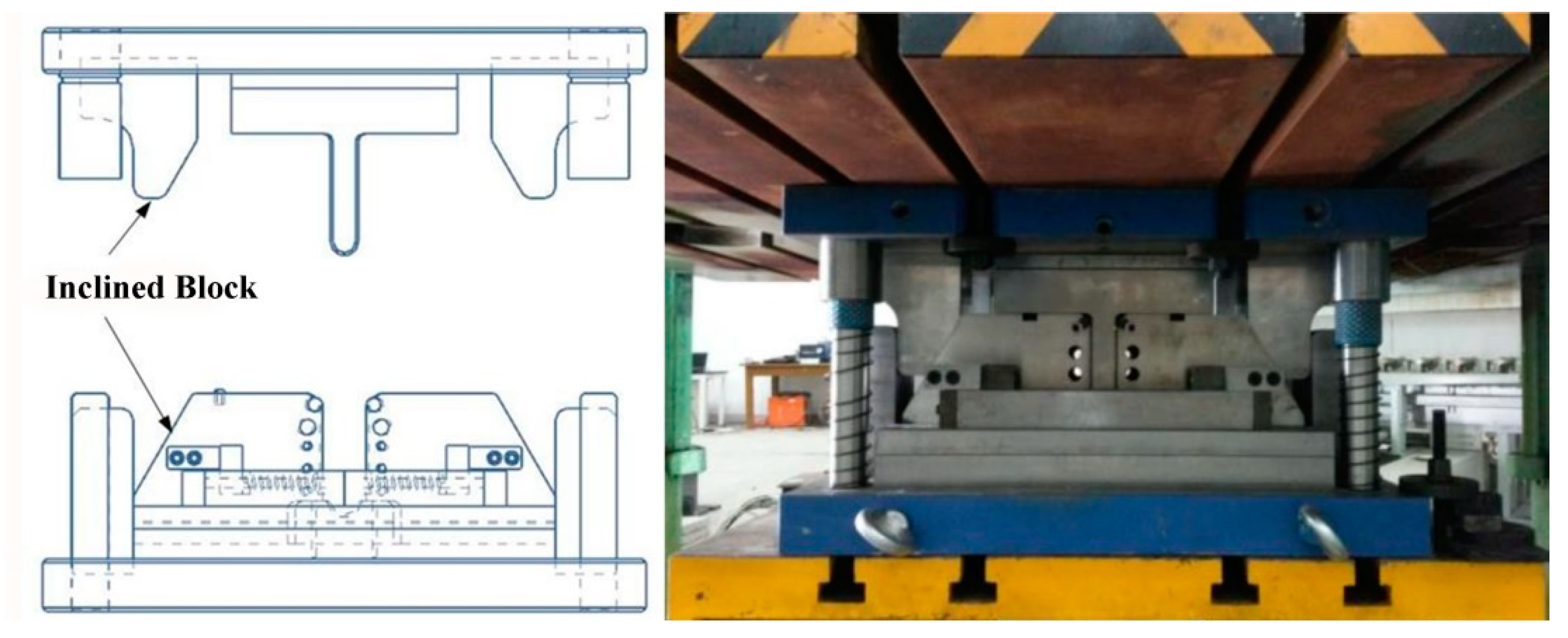
2. Features of the New Product and U-Shaped Tool

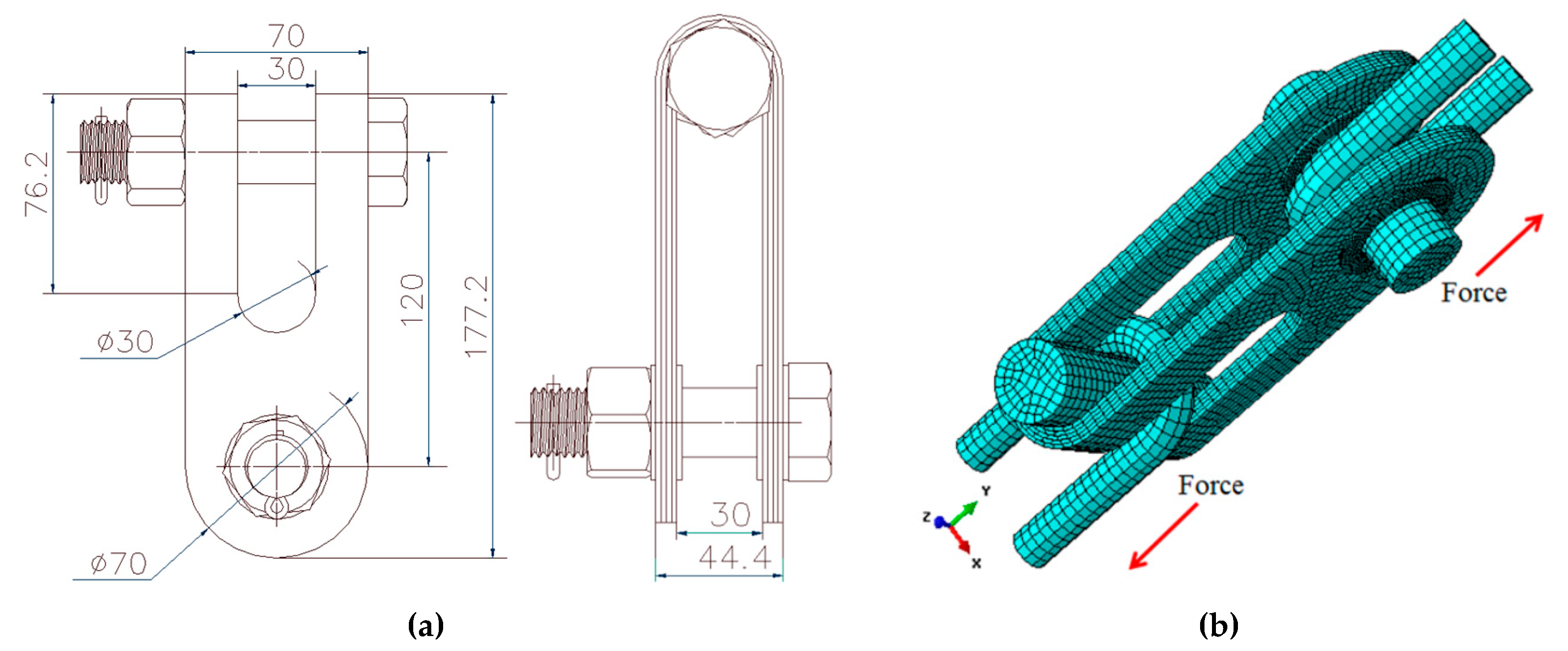
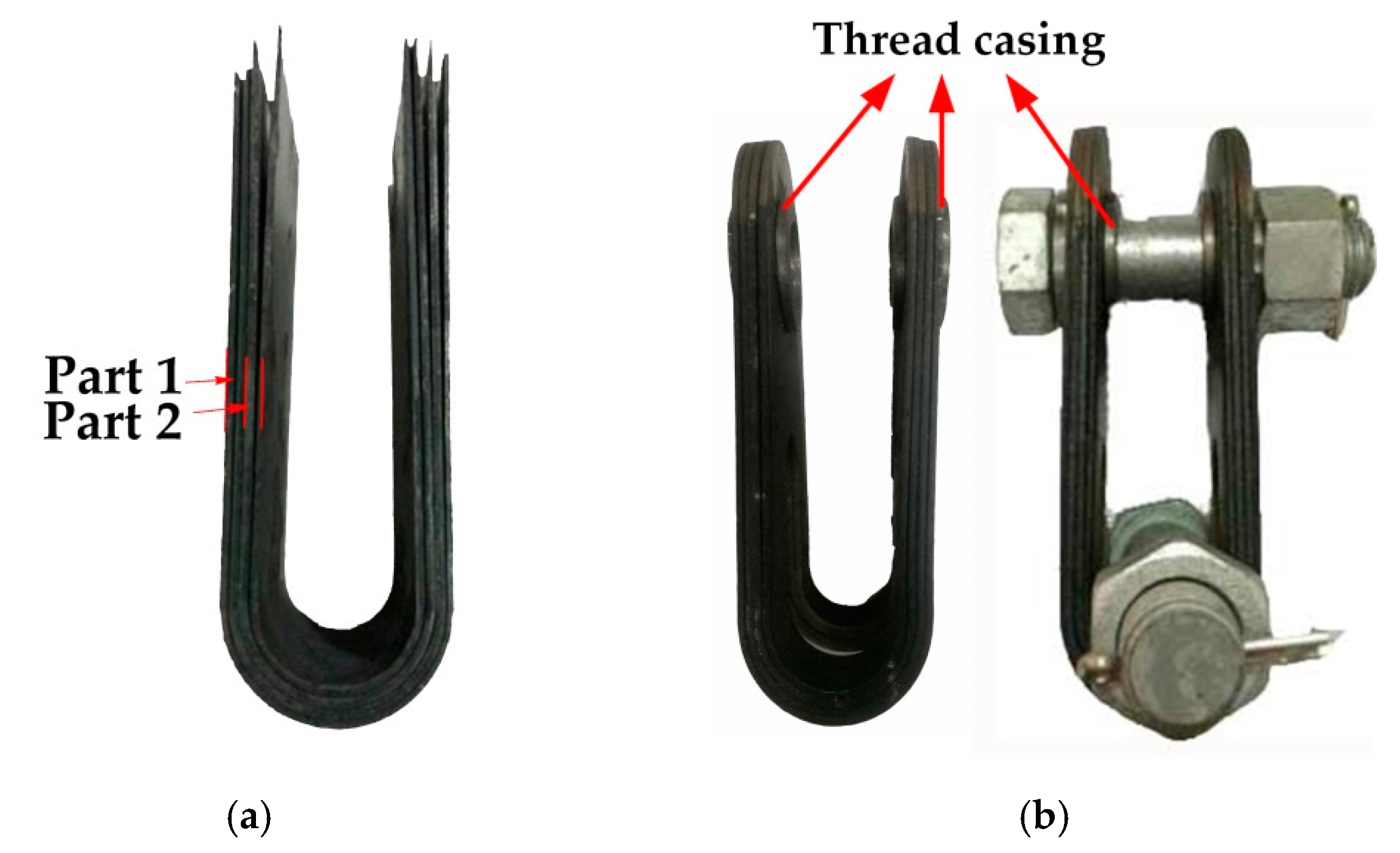
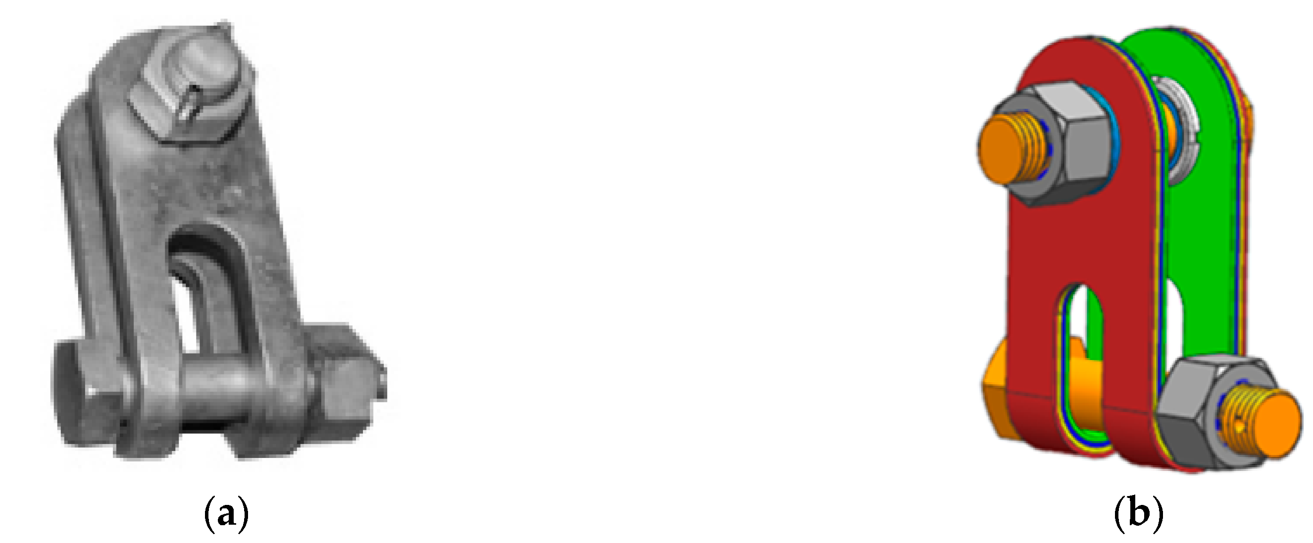
2.1. Light Weight of Clevis-Clevis Component and Features of the U-Shaped Tool

The characteristics of the new type of clevis-clevis are as follows: a deep, symmetrical, U-shaped structure; the load is borne in one direction; and homogeneity in its mechanical properties (Figure 2). Four layers of hot-stamped sheets constituted the U-shaped component with a total thickness of 7.2 mm (the thickness of the traditional clevis-clevis is 15–20 mm). Welding and riveting were applied on the sidewall fillet areas of the four-layer sheets to achieve a rigid and stable connection. The improved structure and alternative material contributed to a strong component with significant weight reduction (above 270 kN load-bearing capacity with a nominal weight of about 2.7 kg). The traditional component bears a load of 240 kN with a nominal weight of about 7 kg [1].
The corresponding U-shaped, hot-stamping tool is shown in Figure 3. With the inclined block, the close contact between tool and sheets was obtained at the quenching stage, which resulted in a more uniform heat dissipation of the multilayered sheets.

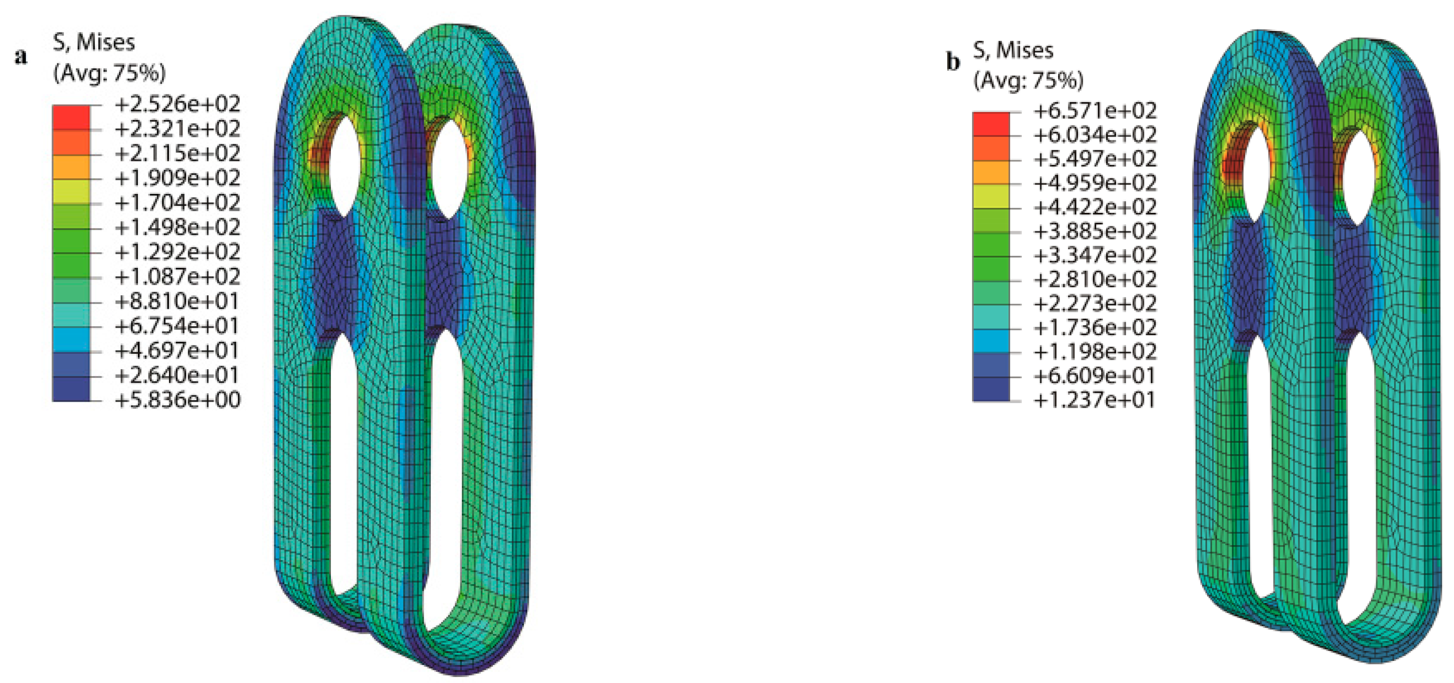
2.2. Numerical Analysis of the Product

The thickness of the single-layered sheet was 1.8 mm. The new type of clevis-clevis with four layers was investigated. Considering the plastic strain behaviors of the component structure, the mechanical property analysis employed an explicit dynamic method [17,18,19]. Furthermore, the model has the same dimensions as the new-type components, as shown in Figure 4a. This was established using ABAQUS software (version 6.13) by using element C3D8R to divide the mesh. The mechanical property analysis employed an explicit dynamic method. Zhou designed a multilayered-sheet component and established a numerical model to predict the mechanical properties of the components. However, the manufacturing process and the experimental investigation were not implemented [7]. A welded constraint was applied for all sheets at the top radius area to avoid the separation among all layers and stress concentration in the pin holes [20]. The bearing condition of the component is depicted in Figure 4b. The material of the connecting parts was SS304. It is the most common stainless steel with less electrically and thermally conductive properties than carbon steel. It has a higher corrosion resistance than regular steel with non-magnetic properties. Thus, the SS304 steel has applications in electrical connecting parts. The material of clevis-clevis was fully martensitic boron steel. The physical and mechanical parameters are shown in Table 1.
The repeated simulations have been implemented. In this work, the element size of 5 mm can guarantee the accuracy without a great loss of efficiency. The calculated result is shown in Figure 5. Under a working load of 80 kN, the maximum stress was 252 MPa, which is 1/3 of the yield strength, distributed in the pinhole region. The maximum stress was 657 MPa under an extreme load of 200 MPa. The stress distribution was nearly uniform in the rest of the regions under both loading conditions. The results indicated that the component can satisfy the requirement with a secure margin.

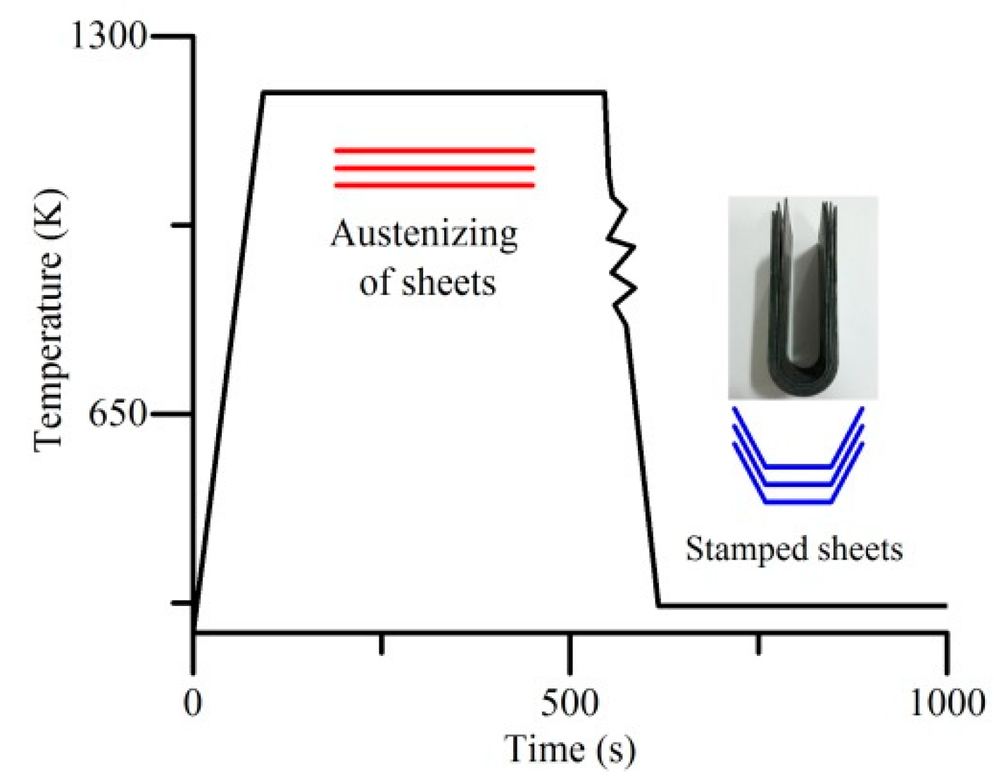
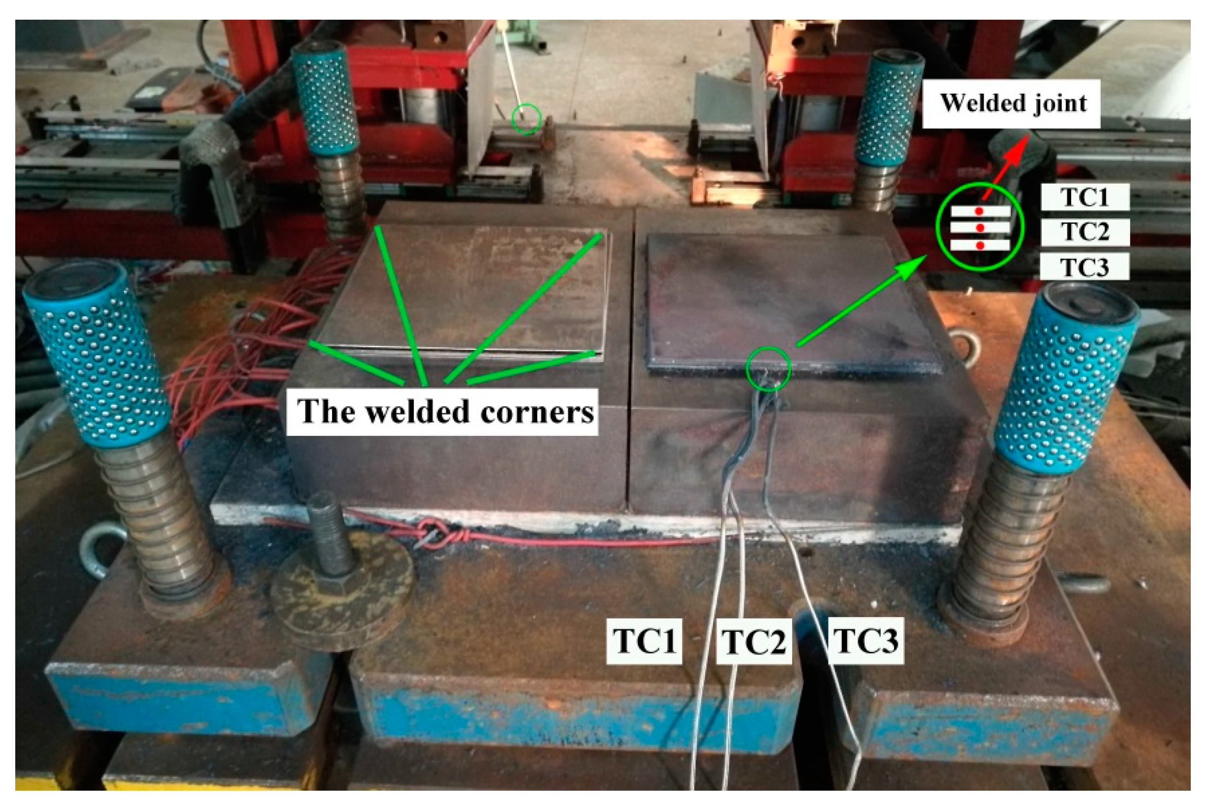
3. Multilayered-Sheet Heat Transfer Experiment

3.1. Experiment Procedure

A multilayered-sheet heat transfer experiment was conducted with a flat tool to investigate the thermal behavior of multilayered sheets during hot stamping and the quenching stages. In this test, 1.8 mm × 190 mm × 185 mm rectangular boron steel sheets were used. Table 2 shows the chemical composition of the steel. As shown in Figure 6, multilayered sheets were welded together at all corners by a resistance spot welder. Thermocouples (TC) were welded at the edge of each sheet to detect the actual temperature history of the sheet during the process. The welded joint of TC and each sheet is depicted in Figure 6. A fast-response temperature measurement and data acquisition system was designed with the National Instruments (NI) acquisition card and some intermediate processing components. The dynamic response of the system was tested, and the results showed that the system could meet the requirements of the temperature data acquisition in hot stamping and the quenching process [13]. Two flat blocks of hot work steel SKD11 with a size of 300 mm × 220 mm × 90 mm constituted the tool. The tool could be heated and maintained at the set temperature with a proportion, integral, differential controller (PID) system. The general test procedure proceeded as follows. Multilayered sheets were placed and held for 4–7 min in a furnace preheated to 1203 K. Then, the sheets were rapidly transferred to the flat die for simultaneous stamping and quenching. The dwelling time was set to 20 s. The numbers of layers were set to 1, 2, 3, and 4. Additionally, the contact pressures were set to 10, 20, 40, and 55 MPa. After hot stamping, the microscopic morphologies and tensile strength of the stamped sheets were investigated.

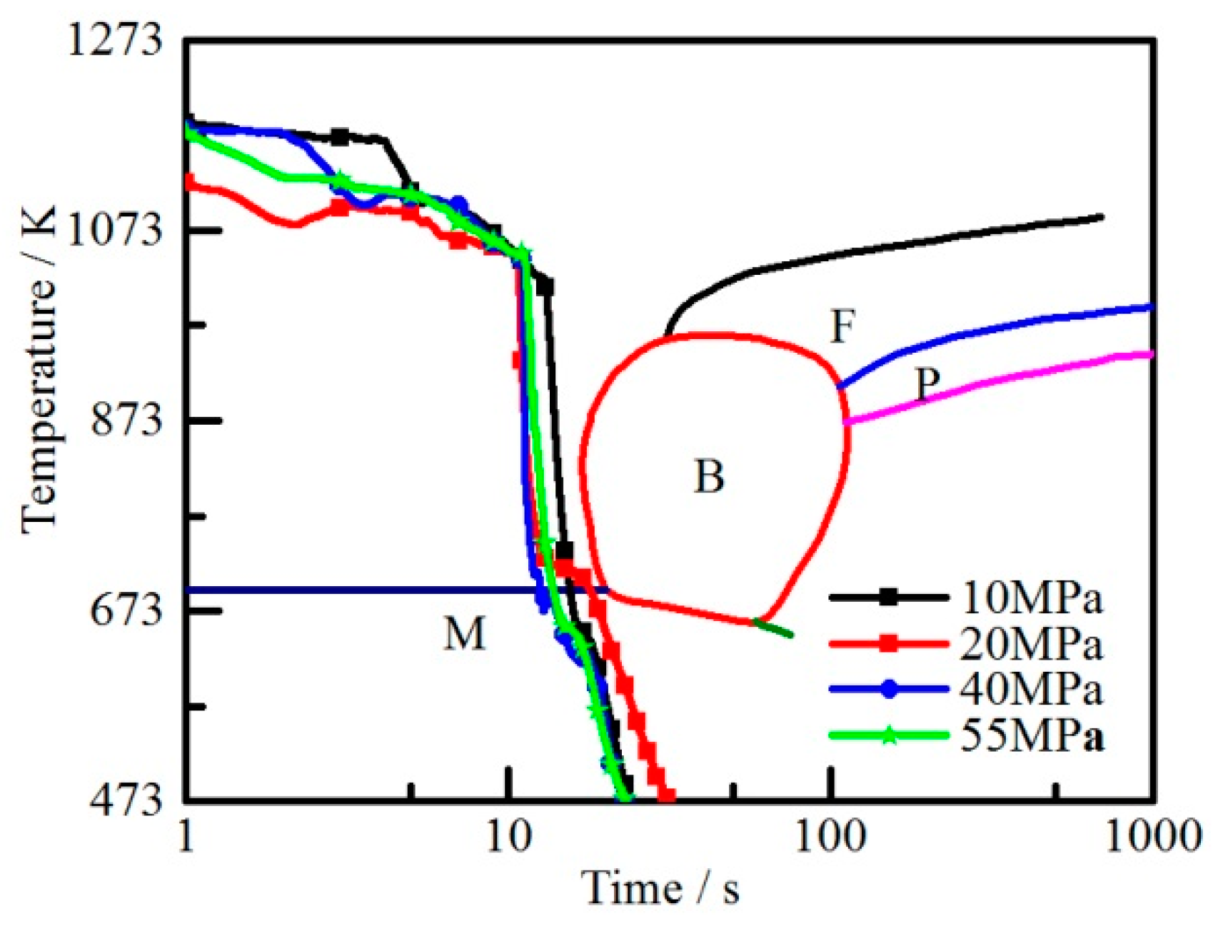
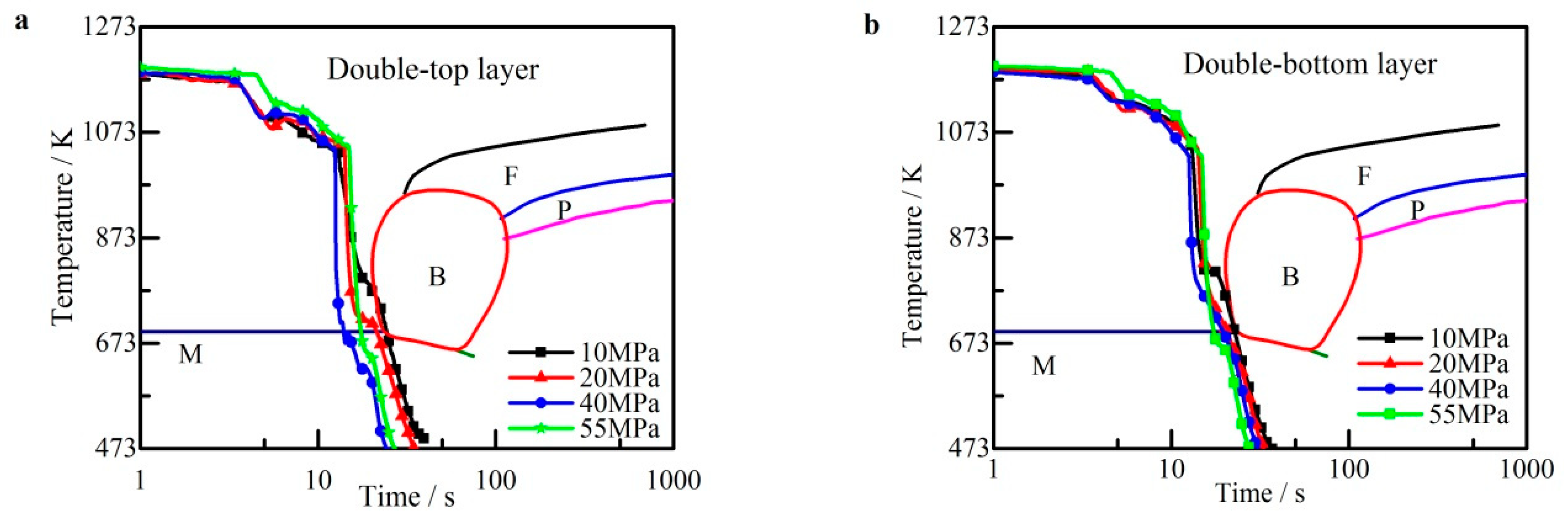
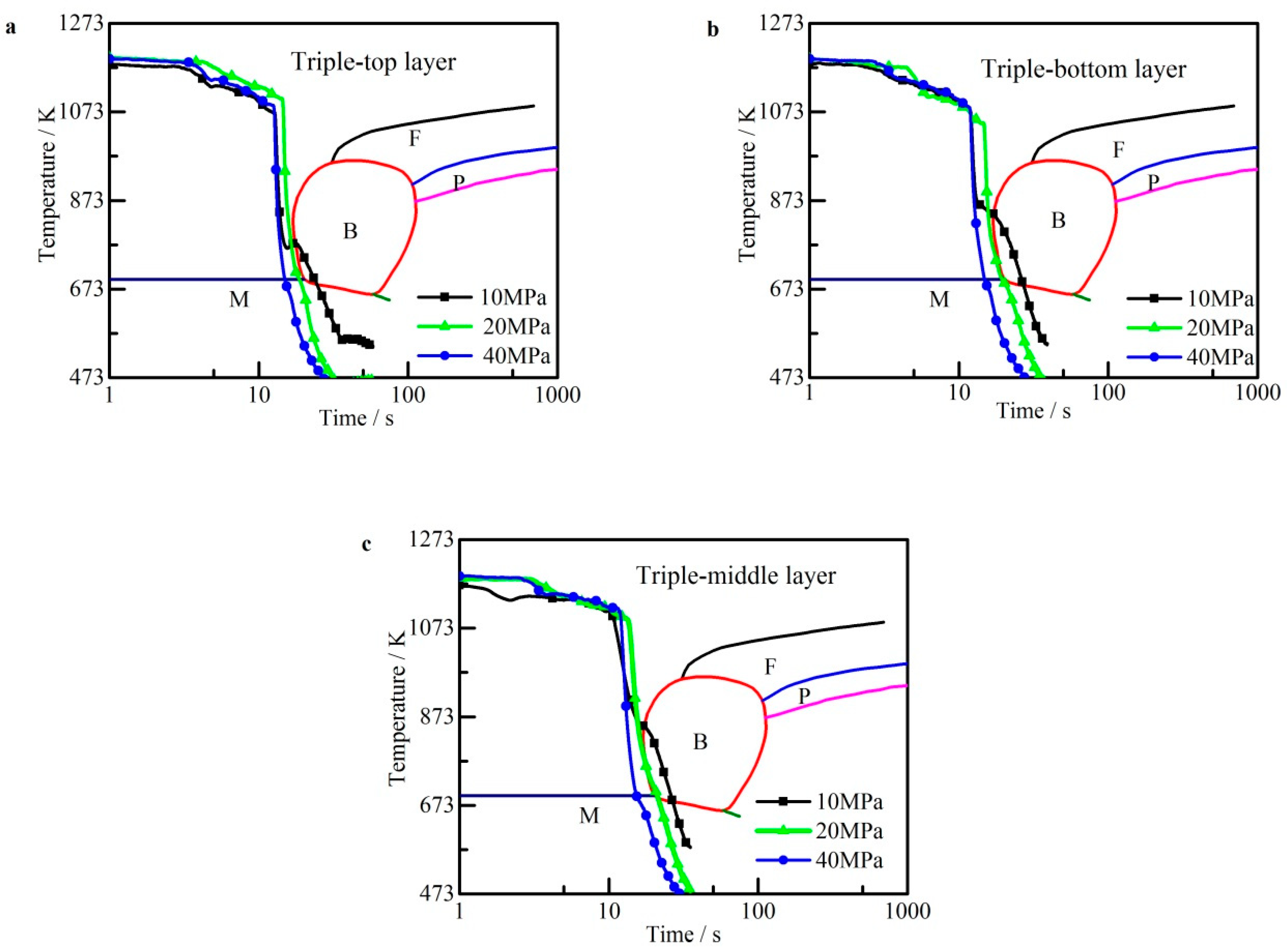
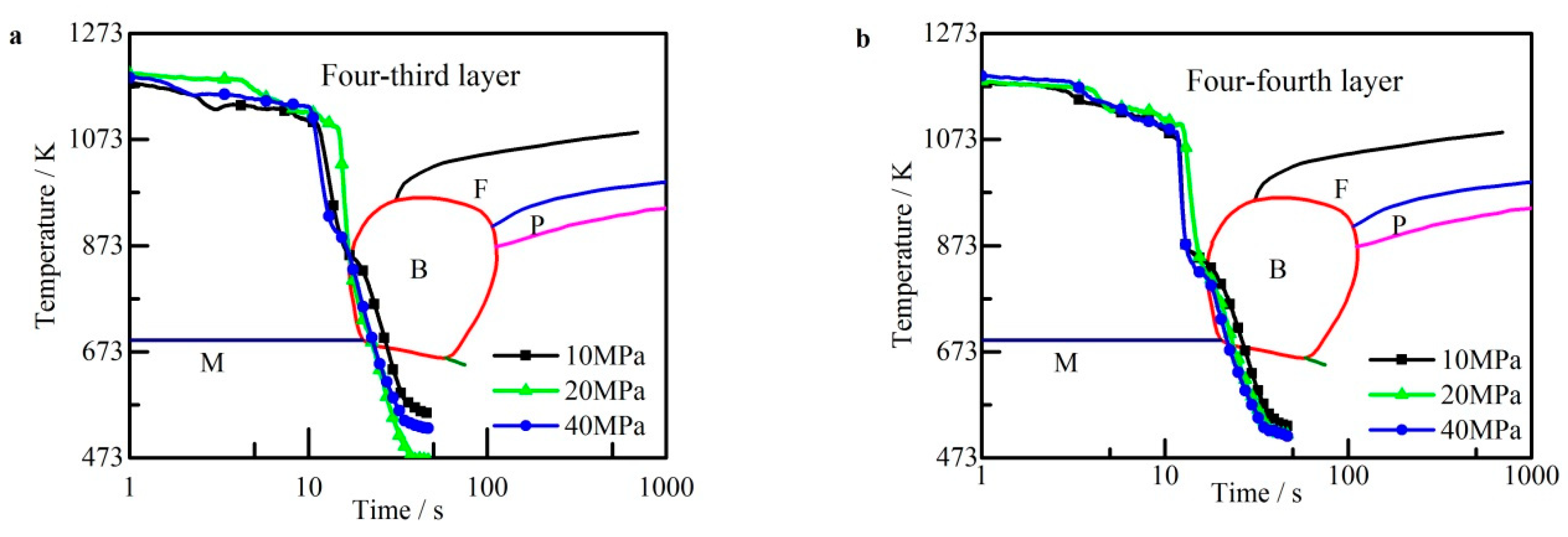
3.2. Temperature Measurement Result

The thermocouple recorded the temperature history of the sheets at the transferring, stamping, and quenching stages. Temperature curves were compared with continuous cooling transformation (CCT) of 22MnB5 steel. The temperature curves of a single-layered sheet at different contact pressures are shown in Figure 7. Although the contact pressure was as small as 10 MPa, the single-layered steel sheet cooled down rapidly at a rate of more than 30 K/s. The temperature curve declined through the single-phase area of martensitic transformation. The cooling rate increased with the contact pressure when it was smaller than 20 MPa and stabilized when the contact pressure exceeded 20 MPa.
The temperature curves of the double-layered sheets at different contact pressures are shown in Figure 8. The bottom and top layers are compared separately. Although the contact pressure was 10 MPa, which resulted in a relatively large contact resistance, both layers completely cooled down at a cooling rate of about 30 K/s. The layers cooled down faster when the contact pressure increased. Meanwhile, the curves indicate that the temperature behaviors of the top and bottom layers under the same pressure were basically similar.
For triple-layered-sheet hot stamping, thermal dissipation was slower in the middle layer than in the outer layers due to a large thermal contact resistance [15]. Whether the middle-layered sheet is completely cooled down determines the final property. The temperature curves of triple-layered sheets at different contact pressures are shown in Figure 9. The same layers from different groups are compared separately. The temperature curves of the top and bottom layers presented a larger slope than that of the middle layer. At a contact pressure of 10 MPa, the temperature curves of all three layers declined through the bainitic transformation area. However, the temperature curves of all layers declined through the edge of the bainitic transformation area at a contact pressure of 20 MPa. The temperature curve of the middle layer declined through the single-phase area of martensitic transformation at a high contact pressure of 40 MPa. Hence, bainitic transformation appeared in the final microstructure of the triple-layered sheets at a contact pressure smaller than 20 MPa. Compared with the scenario in double-layered-sheet hot stamping, contact pressure exerted a greater influence on cooling rate. Moreover, the larger pressure ensured a higher cooling rate. Hence, to obtain a full martensitic transformation, the contact pressure has to be set to more than 40 MPa.
For four-layered-sheet hot stamping, the top layer contact with the punch was defined as the first layer, and the bottom layer contact with the die was defined as the fourth layer. The rest of the sheets were named in order. The temperature curves of the third and fourth layers were obtained (corresponding to the inner- and outer-layer sheets), as shown in Figure 10. The third-layered sheet could not completely cool down even at a contact pressure of 40 MPa. Moreover, the cooling rate of the fourth layer was reduced. The difference between the curves of the third and fourth layers is apparent. Therefore, contact pressure exerted a limited influence on the cooling rate for four-layered-sheet hot stamping. Additionally, the homogenous mechanical property of the group was difficult to obtain when the number of layers was four with a total thickness of 7.2 mm.

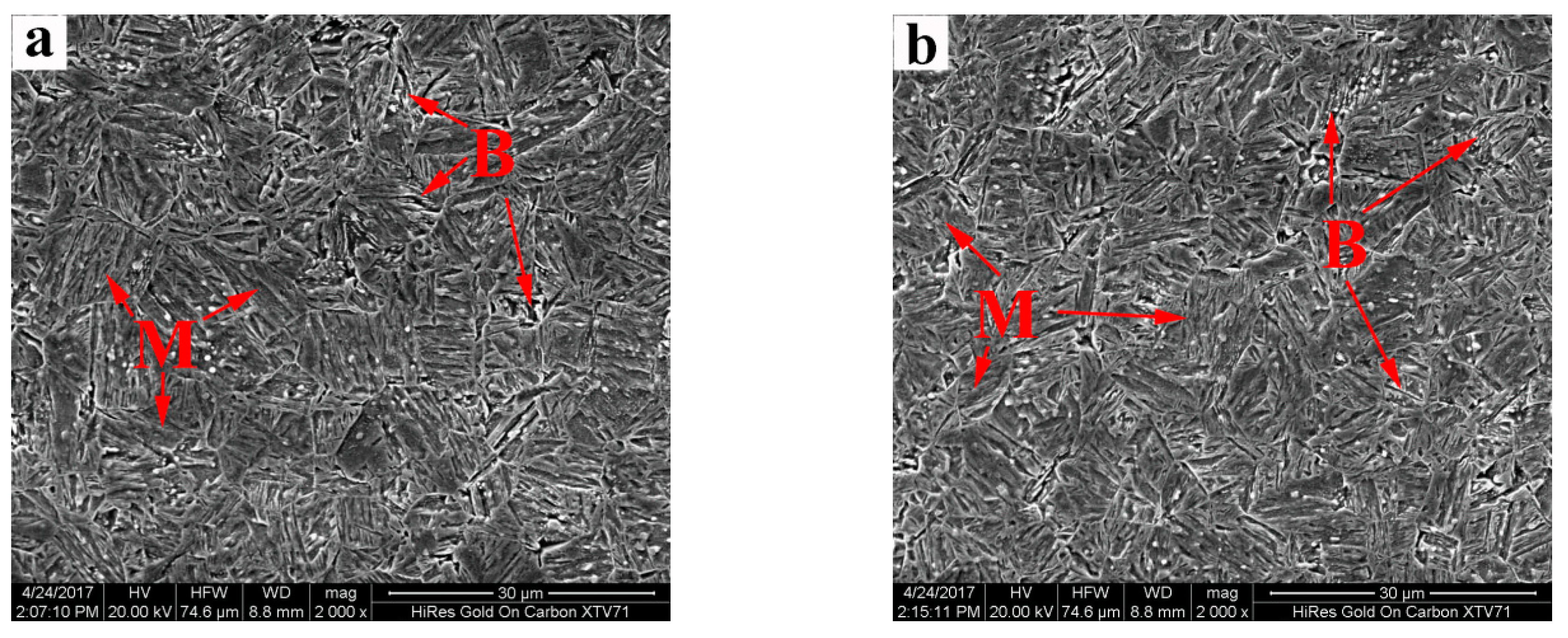
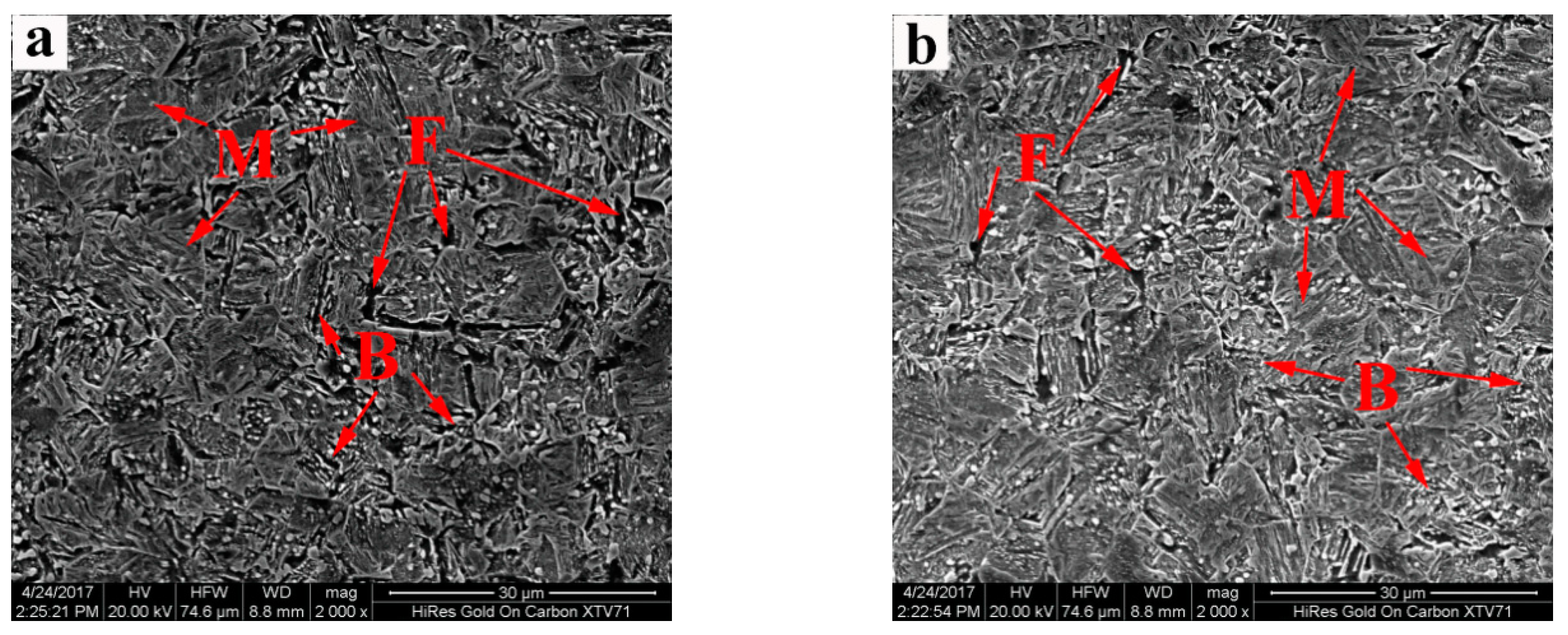
3.3. Microscopic Morphologies of Stamped Sheets
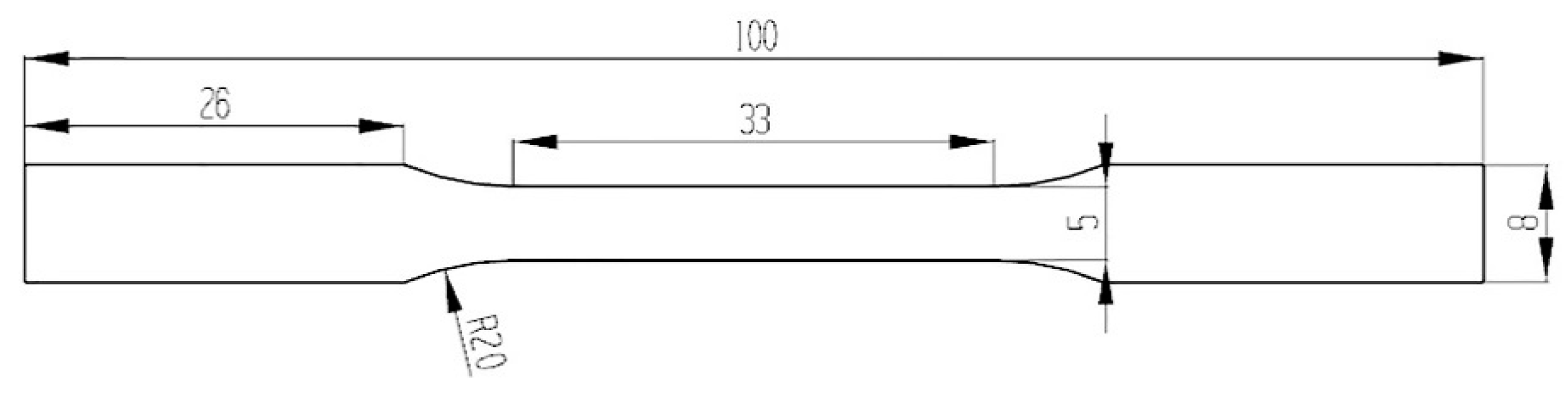
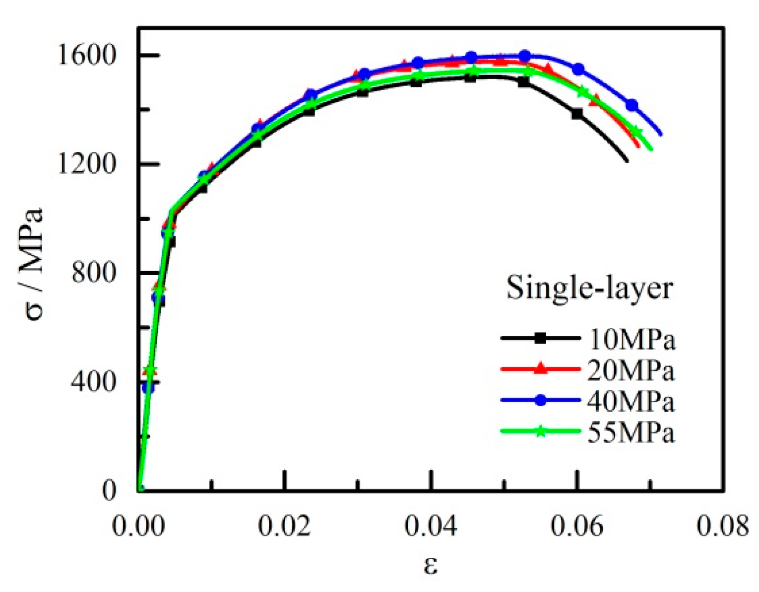
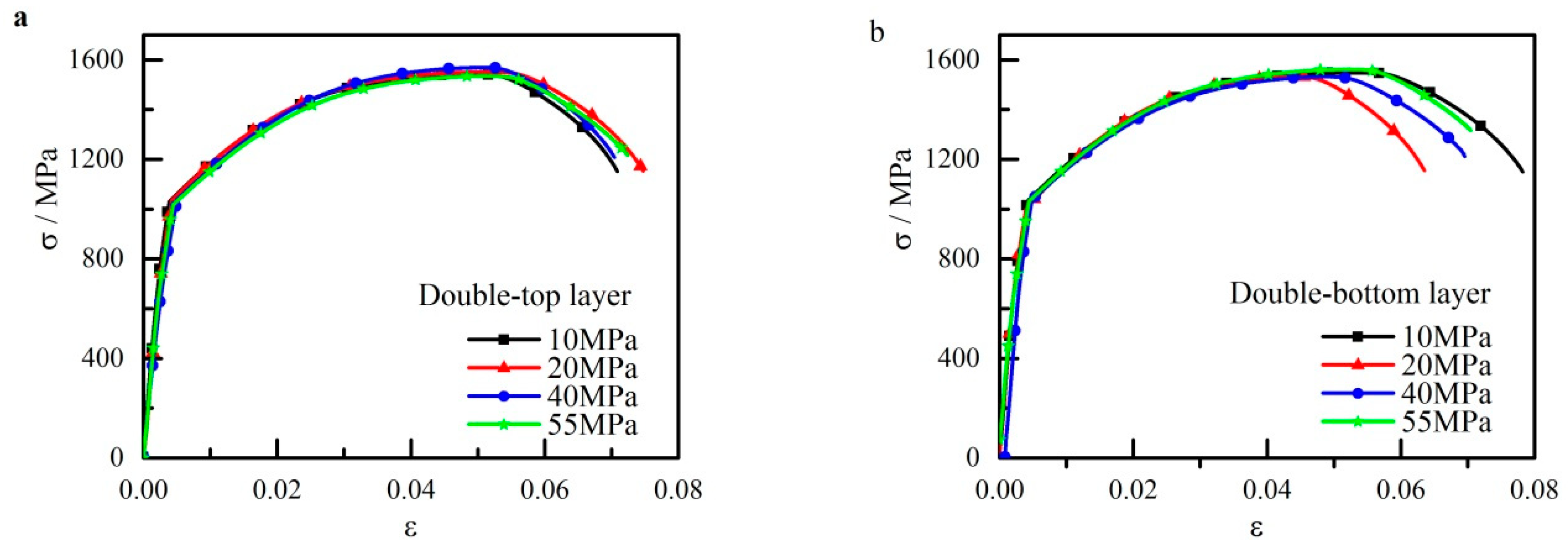
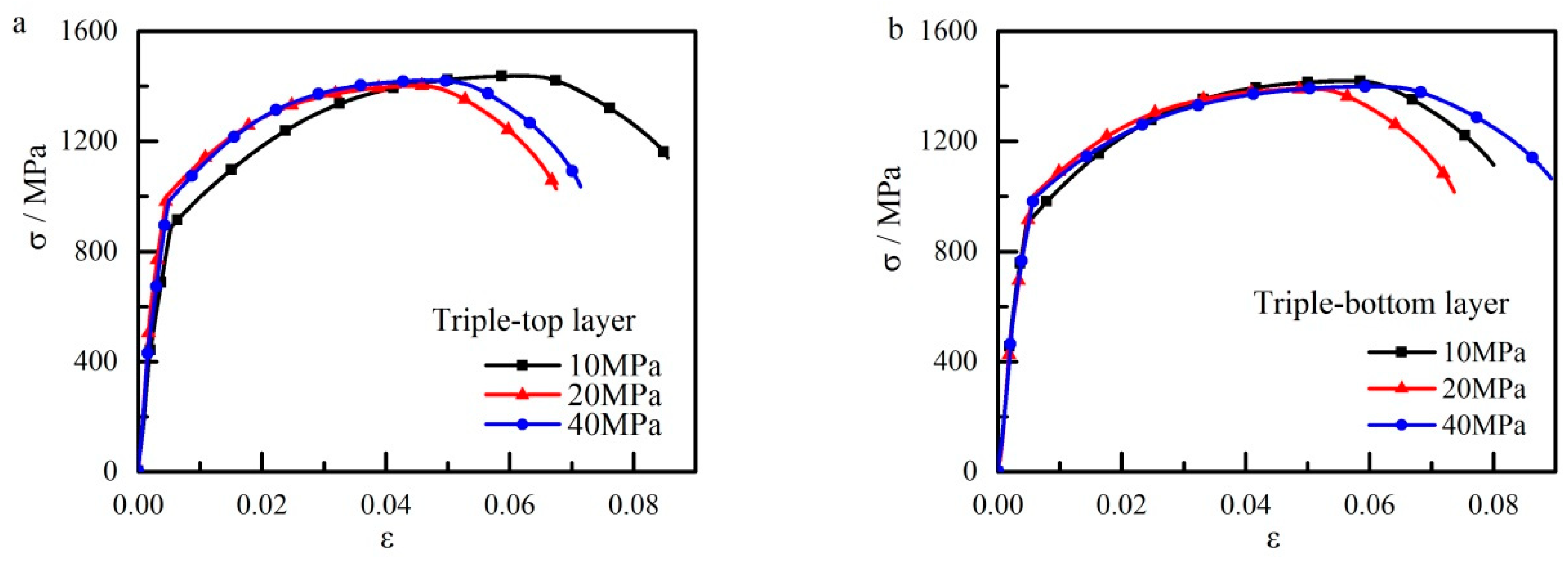
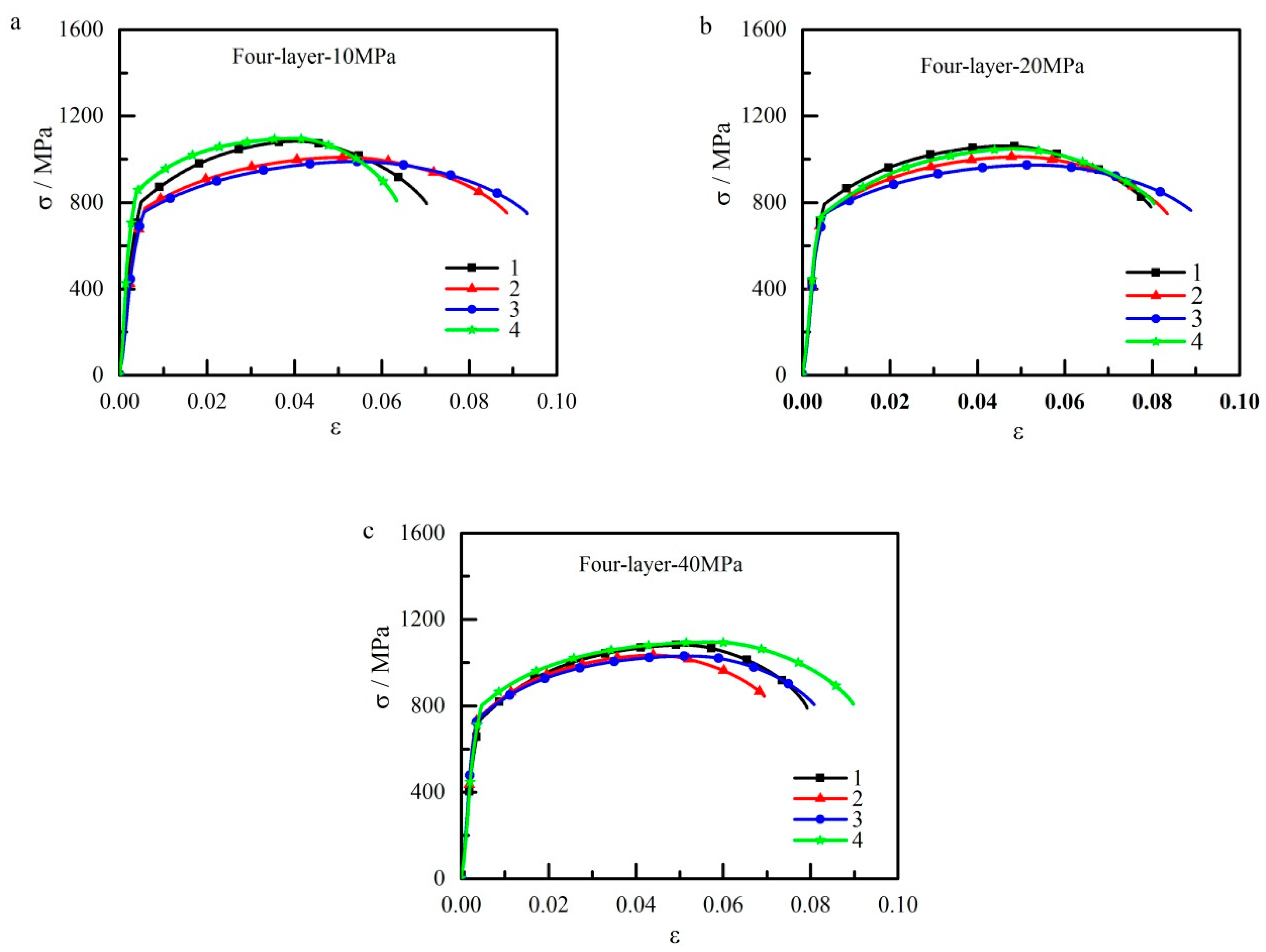
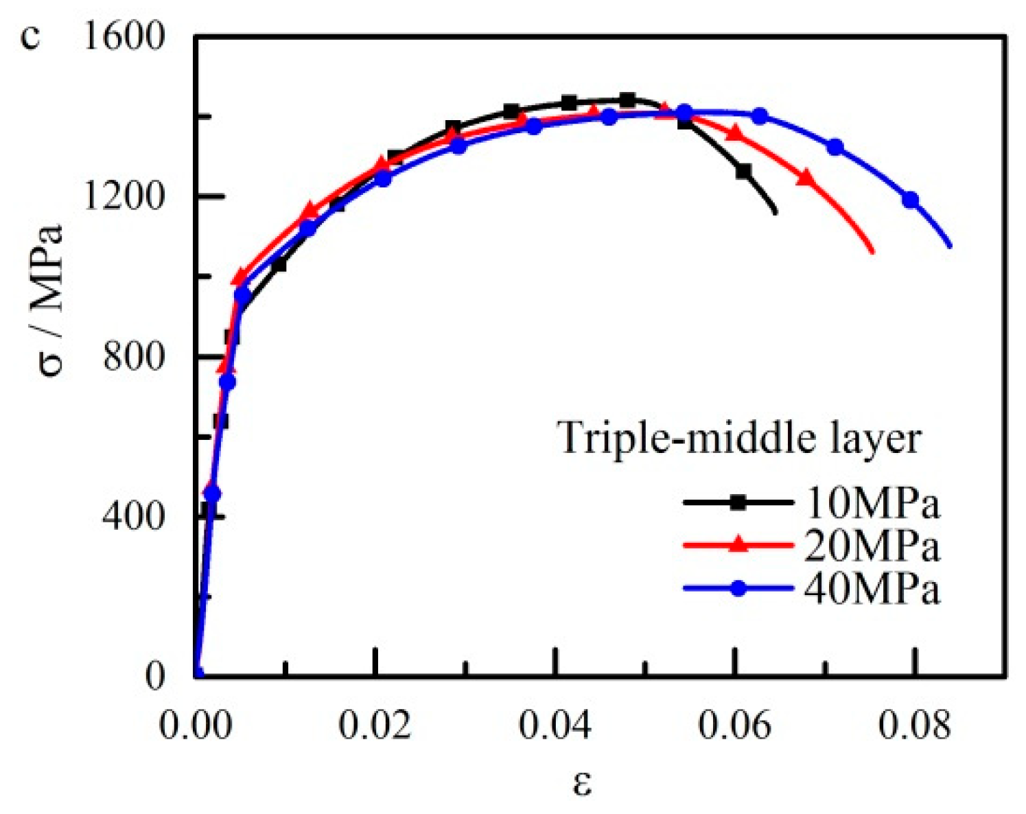
Metallographic specimens were cut from all sheets, mounted, ground, and polished, followed by corrosion with 3% nitric acid alcohol solution. A Quanta200 FEI scanning electron microscope was used to observe the microstructure of the specimens.
The microstructure of the top layer from the double-layered sheets at 20 MPa was set as a reference, as shown in Figure 11, in which the fine lath martensite was evenly distributed. For the triple-layered sheets at 20 MPa, as shown in Figure 12, the microstructures of the top and middle layers were a mixture of a large fraction of lath martensite, with a minor fraction of martensite–bainite being unevenly distributed. The dot martensite-bainite duplex phase accounted for a larger fraction in the middle-layered sheet than in the top-layered sheet.
Figure 13 shows the microstructures of four-layered sheets at 20 MPa; these microstructures are quite distinct from those of the abovementioned groups. The microstructures of both layers comprised a large fraction of lath martensite, a certain fraction of bainite, and a minor fraction of ferrite. The difference between each layer was negligible. This result is the consequence of the low cooling rates of all four layers.
Comparison of the microscopic morphologies and temperature curves revealed the following facts. For multi-layered-sheet hot stamping, when the number of layers is less than three, contact pressure affects the cooling rate, which determines the microstructure of the stamped sheets. When the number of layers is four, the influence of contact pressure on the cooling rate is modest, such that bainitic transformation is inevitable under experimental conditions.

3.4. Tensile Tests

To further verify the mechanical properties of the stamped sheets, tensile tests were conducted. Specimens for tensile testing were machined according to DIN 50114. The dimension of specimens for tensile tests at room temperature is shown in Figure 14. The tensile tests were carried out on a SHIMADZU AG- 100 kN machine with a deformation rate of 2 mm/min. The stress and deformation values were collected during the tests. The experimental results are shown in stress–strain curve.
The engineering stress versus strain curves of the single-layered sheet at different contact pressures are shown in Figure 15. Even at a small contact pressure of 10 MPa, the stamped sheet with a fully martensitic microstructure exhibited a yield strength of about 1200 MPa and a tensile strength of above 1500 MPa. Hence, the single-layered sheet was completely cooled down during the stamping process.
The engineering stress versus strain curves of the double-layered sheets are shown in Figure 16. The strength of the double-layered sheets had the same strength grade as that of the single-layered sheet. Therefore, the cooling rate was high enough to completely cool down the 3.6 mm stacked sheets. The difference between the top- and bottom-layer sheets was negligible.
The engineering stress versus strain curves of the triple-layered sheets are shown in Figure 17. The tensile strength of all layers was about 1400 MPa at a contact pressure of 10 MPa, and the strength increased as the contact pressure increased. At a contact pressure of 40 MPa, the tensile strength reached 1450 MPa. Moreover, the tensile strength of each layer from the same group had a compatible strength grade of 1400 MPa. Hence, the slight difference of the dot martensite-bainite duplex phase barely affected the final property. In contrast to the microstructure of the double-layered sheets, the appearance of the duplex phase resulted in a slight strength reduction. Thus, contact pressure was still the determining factor in the triple-layered-sheet hot-stamping process.
The engineering stress versus strain curves of the four-layered sheets are shown in Figure 18. Every layer from top to bottom was named in order as mentioned above (the layer contact with the punch was the first layer, and the layer contact with the die was the fourth layer). The tensile strength of each layer was less than 1150 MPa even at a pressure of 40 MPa. A certain amount of bainitic transformation significantly influenced the strength reduction. Additionally, the outer layers directly in contact with the tool obtained higher strength than the middle layers; this finding is attributed to the relatively faster cooling rate with a smaller fraction of bainite in the outer layers.
In conclusion, during multilayered-sheet hot stamping, single- and double-layered sheets with a total thickness of less than 3.6 mm could be completely cooled down even at a small contact pressure of 10 MPa. In triple-layered sheets with a total thickness of 5.4 mm, the martensite-bainite duplex phase was unevenly distributed in the stamped sheets at a contact pressure of 20 MPa, which resulted in a slight strength reduction and inhomogeneous properties. To obtain a critical cooling rate of 30 K/s, the contact pressure must be set to more than 40 MPa. While the number of layers is four with a total thickness of 7.2 mm, all sheets could not be cooled down. A certain fraction of bainitic transformation appeared in all sheets at a large contact pressure of 40 MPa, which resulted in a large strength reduction. Hence, to obtain the fully martensitic microstructure, the optimizing parameters for the U-shaped, multilayered-sheet, hot-stamping process are double-layered sheets at a contact pressure of above 20 MPa.

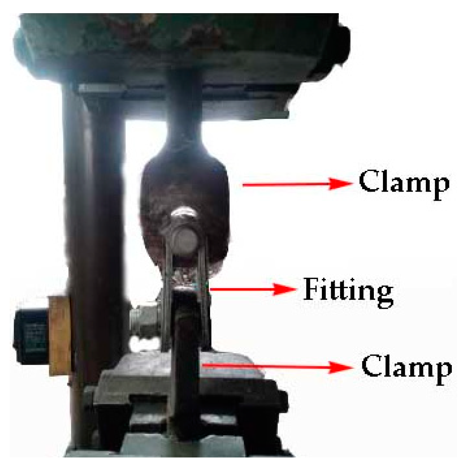
4. New Product and Its Performance Tests

The U-shaped tool can manufacture two parts of a component in one hot-stamping process. The parameters of the U-shaped stamping process were concluded from the above experiment. In this test, prepared sheets with a size of 3.6 mm × 310 mm × 70 mm were used. The double-layered sheets were welded together at all corners by a resistance spot welder. The chemical composition of the steel sheet is shown in Table 2. The double-layered sheets were placed and held for 4–7 min in a furnace preheated to 1203 K. Then, the sheets were rapidly transferred to the U-shaped tool for simultaneous stamping and quenching. The contact pressure was set to 50 MPa. The dwelling time was set to 20 s. Then, the two formed parts were stacked (Figure 19a) and spot-welded at the edges. Then, the pinholes were connected with the bolt, as shown in Figure 19b.
For the new component to meet the national standards of electrical power fittings, the component has to bear 1.2 times of the nominal load without damage, namely 240 kN. The arranged accumulated stress was close to the real work condition. The test procedure was divided into three steps. First, the fitting at both clamps was fixed, loading the fitting to a tensile stress of 200 kN. Then, it was held for 60 s and unloaded. Finally, the loading and holding process was repeated, and it was then loaded to 240 kN and held for 60 s. The fitting is qualified if no fracture appeared. Testing with a dedicated device in an electrical power fitting company in the south of China indicated that when the tension reached 240 kN and even 280 kN, this new type of clevis-clevis exhibited no fracture failure. The experimental diagram of product performance tests is shown in Figure 20.

5. Conclusions

(1) A multilayered-sheet, hot-stamping process was proposed. A model was designed and used to produce an electric-power-fitting product clevis-clevis component by multilayered-sheet hot stamping.
(2) The number of layers and contact pressure were the key process parameters in multilayered-sheet hot stamping; they determined the final microstructure and mechanical properties. When the number of sheets was two and the total thickness was 3.6 mm, each sheet could obtain a fully martensitic microstructure at a relatively low contact pressure of 10 MPa. When the number of layers was three and the total thickness was 5.4 mm, a relatively high contact pressure of more than 40 MPa was needed to ensure an adequate cooling rate. When the number of layers is four, the inner layer could not cool down even at a contact pressure of more than 40 MPa.
(3) U-shaped, double-layered-sheet hot stamping was implemented to produce a typical electrical connection fitting clevis-clevis. The bearing capacity of the four-layered clevis-clevis was tested. The new clevis-clevis component exhibited a large load capacity of 280 kN, which satisfies the requirement with a secure margin. Compared with that of the traditional component, the weight of the new component was reduced by 60%.
(4) Considering actual application status, corrosion protection of the clevis-clevis component is essential [21], and hot galvanization on the surfaces of clevis-clevis to prevent corrosion and reliability for creep deformations of the component will be investigated in future research.

Author Contributions

Conceptualization, B.Z.; Methodology, Y.W. and Y.Z.; Software, Y.J.; Validation, K.W.; Investigation, Z.Z.; Resources, Y.W. and Y.Z.

Funding

This research work was funded by the National Natural Science Foundation of China (grant No. 5140517 and U1564203).

Acknowledgments

The authors would like to acknowledge the Analytic and Testing Center of the State Key Lab of Materials Processing and Die and Mould Technology for their assistance in the tensile tests.

Conflicts of Interest

The authors declare no conflict of interest.

References

  1. Meah, K.; Ula, S. Comparative Evaluation of HVDC and HVAC Transmission Systems. In Proceedings of the Power Engineering Society General Meeting, Tampa, FL, USA, 24–28 June 2007. [Google Scholar]
  2. Liu, S.; Fan, Z.; Gao, M. Analysis of the reasons behind the fracture of the 220kV pipe busbar horizontal line clamp. In Proceedings of the 2016 International Conference on Applied Engineering, Materials and Mechanics (ICAEMM 2016), Weihai, China, 15–17 January 2016. [Google Scholar]
  3. Karbasian, H.; Tekkaya, A.E. A review on hot stamping. J. Mater. Process. Tech. 2010, 210, 2103–2118. [Google Scholar] [CrossRef]
  4. Maider, M.; Garikoitz, A.; Anton, G.; Carlos, A. Effect of the martensitic transformation on the stamping force and cycle time of hot stamping parts. Metals 2018, 8, 385. [Google Scholar]
  5. Mulidrán, P.; Šiser, M.; Ján, S.; Spišák, E.; Sleziak, T. Numerical prediction of forming car body parts with emphasis on springback. Metals 2018, 8, 435. [Google Scholar] [CrossRef]
  6. Hall, J.N.; Fekete, J.R. Steels for Auto Bodies: A General Overview, 1st ed.; Cambridge Woodhead Publishing Press: Cambridge, UK, 2017; pp. 19–45. [Google Scholar]
  7. Zhou, M.L.; Wang, L.; Wang, Z.J.; Wang, Y.L.; Zhang, Y.S. Analysis of the design and mechanical performance about hot stamping power fitting products. Adv. Mater. Res. 2014, 1063, 272–275. [Google Scholar] [CrossRef]
  8. Chang, Y.; Meng, Z.H.; Ying, L.; Xiao-Dong, L.I.; Ning, M.A.; Ping, H.U. Influence of hot press forming techniques on properties of vehicle high strength steels. J. Iron Steel Res. 2011, 18, 59–63. [Google Scholar] [CrossRef]
  9. Yoon, S.H.; Kyu, J.C.; Gil, K.C. Effect on blank holding force on blank deformation at direct and indirect hot deep drawings of boron steel sheets. Metals 2018, 8, 574. [Google Scholar]
  10. Seung, H.L.; Jaewoong, P.; Kiyoung, P.; Dong, K.K.; Hyunwoo, L.; Daeho, Y.; Hongrae, P.; Jaeseung, K. A study on the cooling performance of newly developed slice die in the hot press forming process. Metals 2018, 8, 947. [Google Scholar]
  11. Hay, B.A.; Bourouga, B.; Dessain, C. Thermal contact resistance estimation at the blank/tool interface: Experimental approach to simulate the blank cooling during the hot stamping process. Int. J. Mater. Form. 2010, 3, 147–163. [Google Scholar]
  12. Abdulhay, B.; Bourouga, B.; Dessain, C.; Brun, G.; Wilsius, J. Development of estimation procedure of contact heat transfer coefficient at the part-tool interface in hot stamping process. Heat Transfer Eng. 2011, 32, 497–505. [Google Scholar] [CrossRef]
  13. Wang, C.; Zhang, Y.S.; Tian, X.W.; Zhu, B.; Li, J. Thermal contact conductance estimation and experimental validation in hot stamping process. Sci. China Technol. Sci. 2012, 55, 1852–1857. [Google Scholar] [CrossRef]
  14. Zhu, B.; Zhang, Y.S.; Li, J.; Wang, H.; Ye, Z. Simulation research of hot stamping and phase transition of automotive high strength steel. Material. Res. Innov. 2015, 15, s426–s430. [Google Scholar] [CrossRef]
  15. Wang, Z.J.; Xu, Y.; Zhou, M.L.; Wang, Y.L.; Zhang, Y.S. Valuation method for effects of hot stamping parameters on tailored properties. Adv. Mater. Res. 2014, 1063, 202–206. [Google Scholar] [CrossRef]
  16. Gui, Z.X.; Zhang, Y.S.; Wang, Z.J. Simulation of lightweight B-pillar during hot stamping process with thermo-mechanical-metallurgical model. Stamping Techn. 2012, 37, 193–197. [Google Scholar]
  17. Lee, M.G.; Kim, S.J.; Han, H.N.; Jeong, W.C. Application of hot press forming process to manufacture an automotive part and its finite element analysis considering phase transformation plasticity. Int. J. Mech. Sci. 2009, 51, 888–898. [Google Scholar] [CrossRef]
  18. Bok, H.H.; Lee, M.G.; Pavlina, E.J.; Barlat, F.; Kim, H.D. Comparative study of the prediction of microstructure and mechanical properties for a hot-stamped B-pillar reinforcing part. Int. J. Mech. Sci. 2011, 53, 744–752. [Google Scholar] [CrossRef]
  19. Tang, B.; Wang, Q.; Wei, Z.; Meng, X.; Yuan, Z. FE simulation models for hot stamping an automobile component with tailor-welded high-strength steels. J. Mater. Eng. Perform. 2016, 25, 1709–1721. [Google Scholar] [CrossRef]
  20. Yanzhong, J.U.; Jiang, F.; Dehong, W.; Lili, M.; Shuzhen, Z. Ultimate bearing capacity analysis of safety pin based on nonlinear contact. Water Resour. Power 2012, 7, 173–175. [Google Scholar]
  21. DžUpon, M.; Falat, L.; Slota, J.; Hvizdoš, P. Failure analysis of overhead power line yoke connector. Engineering Fai. Anal. 2013, 33, 66–74. [Google Scholar] [CrossRef]
Figure 1. Multilayered-sheet, hot-stamping process.
Metals 09 00215 g001
Figure 2. Structure of (a) the traditional clevis-clevis and (b) the new clevis-clevis.
Metals 09 00215 g002
Figure 3. U-shaped, multilayered-sheet, hot-stamping tool.
Metals 09 00215 g003
Figure 4. (a) The dimensions and (b) the finite element (FE) model of the new type of clevis–clevis. (Units: mm).
Metals 09 00215 g004
Figure 5. Equivalent stress distribution under different loads: (a) 80 kN and (b) 200 kN.
Metals 09 00215 g005
Figure 6. Schematic of the flat die experiment.
Metals 09 00215 g006
Figure 7. Temperature curves of a single-layered sheet.
Metals 09 00215 g007
Figure 8. Temperature curves of the double-layered sheets: (a) top layers and (b) bottom layers.
Metals 09 00215 g008
Figure 9. Temperature curves of triple-layered sheets: (a) top layers; (b) bottom layers; (c) middle layers.
Metals 09 00215 g009
Figure 10. Temperature curves of four-layered sheets: (a) third layer; (b) fourth layer.
Metals 09 00215 g010
Figure 11. Microscopic morphology of the top layer from double-layered sheets at 20 MPa.
Metals 09 00215 g011
Figure 12. Microscopic morphologies of triple-layered sheets at 20 MPa. (a) top layer and (b) middle layer.
Metals 09 00215 g012
Figure 13. Microscopic morphologies of four-layered sheets at 20 MPa, (a) third layer and (b) fourth layer.
Metals 09 00215 g013
Figure 14. Dimension of specimens for tensile test at room temperature. (Unit: mm).
Metals 09 00215 g014
Figure 15. Stress-strain curves of the single-layered sheet.
Metals 09 00215 g015
Figure 16. Stress-strain curves of the double-layered sheets. (a) top layer and (b) bottom layer.
Metals 09 00215 g016
Figure 17. Stress–strain curves of triple-layered sheets. (a) Top layer, (b) bottom layer, and (c) middle layer.
Metals 09 00215 g017aMetals 09 00215 g017b
Figure 18. Stress-strain curves of the four-layered sheets: (a) 10 MPa, (b) 20 MPa, and (c) 40 MPa.
Metals 09 00215 g018
Figure 19. (a) The formed parts and (b) new type of clevis-clevis.
Metals 09 00215 g019
Figure 20. The experimental diagram of product performance tests.
Metals 09 00215 g020
Table 1. Physical and mechanical parameters of the boron steel.
MaterialDensity (kg/m3)Modulus of Elasticity (GPa)Poisson’s RatioYield Strength (MPa)Tensile Strength (MPa)Tangent Modulus (GPa)
Fully martensitic boron steel78301800.293110015501.2
Table 2. Chemical composition of the 22MnB5 substrate in wt.%.
CMnBPSSiCrTiNi
0.231.20.00190.010.0020.170.240.0231.5

