Article

Process Optimization on Multilayer Morphology During 316L Double-wire CMT+P Deposition Process

1
School of Mechanical and Automotive Engineering, South China University of Technology, Guangzhou 510641, China
2
Guangdong Welding Institute (China-Ukraine E.O.Paton Institute of Welding), Guangzhou 510650, China
*
Author to whom correspondence should be addressed.
Metals 2019, 9(12), 1334; https://doi.org/10.3390/met9121334
Submission received: 5 November 2019 / Revised: 6 December 2019 / Accepted: 9 December 2019 / Published: 11 December 2019

Abstract

:
Cold metal transfer (CMT) has been widely used in metal additive manufacturing for its low heat input, less splashing and high efficiency. Wire feeding speed and travelling speed are important processes that affect morphology in CMT deposition. This study optimized the forming process of 30-layer stainless-steel part deposited by double-wire and double-arc CMT plus pulse (CMT+P) process, and investigated the effect of the ratio of wire feeding speed to travelling speed on deposition morphology. The results show that asynchronous arc striking and extinguishing can improve the forming. Moreover, the deposition molding is affected by the interaction of heat input and heat accumulation. With the similar ratio of wire feeding speed to travelling speed and the similar heat input, increasing the wire feeding speed can increase the heat accumulation and the width of sample, and decrease the height. The optimum process interval of wire feeding speed to travelling speed ratio and heat input is 3.9–4.2 and 70–74.8 J/mm, respectively. Although the increasing heat accumulation makes grain coarse and slight decreases mechanical property, the highest deposition rate can be up to 5.4 kg/h, when wire feeding speed and travelling speed are 5 m/min and 120 cm/min, respectively, and the tensile strength and elongation rate of which can reach the basic standard requirements for stainless-steel forgings.

1. Introduction

316L stainless steel has been widely used in aerospace, automobile structure, surgical tools and medical equipment for its good corrosion resistance, high extensibility and biocompatibility. However, it is difficult to manufacture high density structural parts efficiently by traditional manufacturing methods such as casting or powder metallurgy [1]. Depositing material by layers has a widely application in various fields [2]. Pere Barriobero-Vila et al. [3,4] researched the manufacture of titanium alloy structural parts to achieve anisotropy reduction and exploited the IHT of the LMD process for fabricating Fe-19Ni-xAl maraging steel parts that were precipitation strengthened during the additive manufacturing process without need for any further heat treatment. Additive manufacturing by wire is popular used for fabricating metal due to accurate wire controlling [5], high efficiency and low cost, but its large heat input makes it difficult to control the molding [6]. As an improved metal inert gas welding, cold metal transfer (CMT) provides the lowest energy and adopts the unique reciprocating wire process [7], which leads to the advantages of low heat input and less splashing [8]. Therefore, it can realize continuous deposition and high efficiency.
Wire feeding speed is important to the final quality of the product [9,10]. The relationship between wire feeding speed (WFS) and travelling speed (TS) has a great effect on the deposited morphology [11,12,13]. Gomez Ortega et al. [11] studied the influence of speed and power on the forming of single welding and multilayer deposition walls by CMT process, and then concluded that gradually increasing TS could realize the uniform width of the deposition. Moreover, Kazanas et al. [12] adopted CMT process to manufacture upright and inclined walls with ER70S-6 and ER4043 wires, and studied the matching process between WFS and TS. The results revealed that the molding was good when the WFS/TS ratio was in a certain proportion of 15. Similarly, Xu et al. [13] researched the process region of maraging steel by CMT single-pass deposition, the results indicated that when WFS and WFS/TS ratio were greater than 6 m/min and 20, respectively, the forming was acceptable.
The CMT plus Pulse (CMT+P) process is developed by adding pulse into CMT welding, which realizes alternating transition between CMT and pulse during welding [7], and the heat input can be adjusted freely. In addition, the CMT+P process can refine the droplet by pulse, which could effectively reduce the number and size of porosity [14]. Furthermore, CMT+P process has smaller penetration depth and similar deposition width than CMT. Thus, CMT+P is an appropriate process for material deposition. Ayarkwa et al. [15] built aluminum alloy part by CMT+P mode, and the forming was perfect when the WFS/TS ratio was about 16, however, the WFS/TS ratio of stainless-steel deposition by CMT+P process have not been studied.
Increasing wire feeding speed means increasing the current in single-wire deposition, which will result in a limitation in improving efficiency. The double-wire process could not only realize different compositions of alloy deposition [16], but also further improve the deposition efficiency [17]. However, as arc striking and extinguishing process also influence the deposition morphology [18], arc striking and extinguishing sequence of each wire need to be coordinated in double-wire AM, but there are few studies on arc striking and extinguishing process optimization in double-arc additive manufacturing.
Based on the above analysis, the relationship between WFS/TS, thermal input and heat accumulation, and the influence of heat accumulation on the forming morphology of 316L in CMT+P process by twin wires additive manufacturing have not been reported in the literature to date.
Accordingly, this study optimized arc striking and extinguishing in double-wire deposition of 316L stainless steel, and investigated the unified parameter curve of the welding machine. The relationship between heat energy consumption per millimeter of welding wire, WFS/TS ratio and heat input was put forward. Furthermore, with similar heat input and WFS/TS ratio, the effects of different WFS and TS on forming were studied. The optimized process range of deposition forming was obtained by experiments.

2. Materials and Methods

2.1. Test Materials and Equipment

Two 316L stainless-steel wires with 1.2 mm diameter and 250 mm × 100 mm × 5 mm 316L base plate were selected for the test. Before the test, the plate surface was polished. The CMT welding additive manufacturing system consisted of two Fronius TransPlus Synergic 5000 CMT (Fronius International GmbH, Wels, Austria) welding power supplies, two VR 7000 CMT wire feeders (Fronius International GmbH, Wels, Austria), a high-precision KUKA six-axis robot (KUKA Roboter GmbH, Augsburg, Germany) and a double-wire welding gun (Fronius International GmbH, Wels, Austria) with hydraulic water-cooling system, which is shown in Figure 1.

2.2. Experiment Conditions

The shielding gas was 99.99% highly pure argon and the gas flow was 20 L/min. The wire extension was 12 mm and the welding supply adept automatic detection and self-adjustment of arc length, which would avoid arc extinguishing even at high speed.
A 160 mm long weld was deposited to perform 30-layer part and the odd layers were deposited in the opposite direction to the even layers. The deposited parameters of different speeds are shown in Table 1, the voltage and current were matched with the wire feeding speed by the intelligent welding machine. Half the travelling speed was chosen in the first layer for the cold substrate [19].
Due to the reciprocating deposition, the double wires were deposited with the same welding parameters. Although the weld reinforcement was relatively large on the first layer, uneven continuity still occurred between two wires when arcs were synchronous striking. Moreover, there were big cladding at the start and small cladding at the end, which would affect the morphology of both ends of the deposition. Therefore, the setting of arc striking and extinguishing should be first adjusted.
After deposition, the transverse sections were cut to prepare the microstructure and hardness samples. The greasy dirt on the surface of metallographic samples was wiped away using acetone, and then, the samples were cold inlaid. After that, 180#, 600#, 800#, 1200#, 2500# and 5000# sandpapers were used for grinding until the surface without noticeable scratches. Then, the samples were polished with diamond polishing agent of 2.5 μm particles. Finally, samples were corroded by aqua regia (HCl:HNO3 = 3:1) for 30 s, followed by rinsing with clear water and alcohol, and drying. The microstructural characteristics of the depositions were analyzed with an optical metallographic microscope and the microhardness in the deposited direction was tested with a HMV-2T micro Vickers hardness tester ((SHIMADZU Ltd, Kyoto, Japan). A load of 0.5 kg was maintained for 10 s during the test. Points were measured with an interval of 0.5 mm along the deposition direction on the metallographic cross-section, then, the average layer hardness values were calculated and compared.
Three transverse tensile samples H1, H2 and H3 were extracted from the samples, respectively, and the gauge size of the tensile specimen is 12 mm × 3 mm × 1.5 mm. According to GB/T 228/2002 standards, the electronic universal testing machine CMT5105 (Shenzhen New Sanxin material testing Co., Ltd., Shenzhen, China) with the maximum load of 50 kN was used for the tensile test at the rate of 2 mm/min in room temperature. A NOVA NANO (FEI, Eindhoven, Netherlands) scanning electron microscope (SEM) 430 was used to observe the fracture morphologies of snapped samples.

3. Results and Discussion

3.1. Arcing and Extinguishing Process Optimization of Double-Wire CMT Welding

Current setting curve of arcing and extinguishing in the welding process are shown in Figure 2. Where Is and Ie are respectively the proportion of arc striking and extinguishing current to the average deposition current. Furthermore, ts and te represent the time of arc striking and extinguishing, respectively. However, Sl1 and Sl2 represent the transition of arc striking and extinguishing to welding stage, respectively.
As shown in Table 2, four tests of single layer and double-wire deposition were carried out by changing the main parameters of arcing and extinguishing. Sample #S1 was welded by initial parameters, due to the simultaneous arc striking and extinguishing of two wires, and ts was turned off, two large cladding balls existed at the starting position, and then immediately a small amount of cladding was welded by average welding current, as shown in the yellow dotted line frame in #S1 in Figure 3a, which would lead to the instability of the subsequent deposition. A sample of 30 layers was continuously deposited by arc striking and extinguishing parameters of #S1. Due to the uneven weld at arc striking on the first layer, the second and third layers on the lower-left part of the deposition flowed and affected the forming morphology, as shown in the yellow ellipse in Figure 3b. #S2 reduced the arc striking current and prolonged the arc striking time, which made the welds of two wires continuous, as shown in the yellow dotted line, while #S3 increased the arc extinguishing current and prolonged the transition time from welding to arc extinguishing, which enlarged the ending weld, as shown in the red dotted line in Figure 3a.
Although #S3 improved the start and the end welds, since the twin wires had 6 mm distance approximately, their synchronous arc striking and extinguishing resulted in only one wire welding on the left and right ends, therefore the process parameters could not be adjusted to further improve the forming. Based on the above analysis, non-synchronous striking and extinguishing of double-wire should be adopted, which is shown in Figure 4. According to the order of step 1 to step 4, wire 1 started arcing at point A and travelled 6 mm, then wire 2 started arcing, which made two wires depositing at the same point A. When wire 1 extinguished arc at point B and travelled 6 mm, then wire 2 extinguished the arc, so that two wires both extinguished arc at point B. Therefore, the two wires were all welded from A to B, and the improved weld #S4 is shown in Figure 3a.

3.2. Morphology Optimization of Deposited Samples

By changing WFS and TS to adjust heat input, process parameters and deposition morphology, and post-deposition heat accumulation effect are shown in Table 3, due to the limitation of welding supply, the least value of wire feeding speed was 2.5 m/min on CMT+P mode for 1.2 mm diameter 316L, however, the heat input was too high to deposit when WFS was over 5.5 m/min, which lead to metal flow of the upper part of the deposition.
As shown in Table 1, samples #CP2.5, #CP3, #CP3.5, #CP4, #CP4.5, #CP5 and #CP5.5-138 had the similar heat input around 140 J/mm, however, different travelling speeds resulted in different thermal accumulations. It can be seen from the hot and cold regions of samples after deposition in Table 3 that with the increase of WFS and TS at the same time, the interval time of each deposited point was shortened, which might lead to the increase of thermal accumulation, resulting in larger red and hot areas of the sample. Moreover, the height of the deposition decreased and the thickness gradually increased [20].
From the back pictures of the substrate in Table 3, the thermal influence of two ends of the deposition on the substrate was different, and the right effect was greater than that of the left, which was mainly due to the different heat accumulations. The right end underwent fifteen times continuous heat accumulations, while the left end underwent fourteen times. Therefore, the total heat accumulation at the right end was greater than that at the left. The back heat affected area of the substrate was mainly determined by the thermal input and accumulation. As the heat input of #CP5.5-150 was relatively small, the back heat affected area was smaller than others.
As the deposition rate of #CP2.5 was the lowest, the wall was the thinnest and highest, and the surface was uneven. Due to the small thermal accumulation and width, the right end of the sample was slightly cocked for the thermal stress after deposition. However, decreasing TS would lead to the increase of thermal stress, while increasing TS would make the sample discontinuity. Therefore, the wire feeding speed could not be lower than 2.5 m/min. For the large power, #CP5.5-138 had the smallest height and the biggest thickness. Decreasing TS would make large thermal input and metal flowing, while increasing TS produced more serious heat accumulation, which would also lead to serious flowing on the upper part, such as sample #CP5.5-150, as presented in Table 3. Due to the influence of thermal input and heat accumulation, the highest WFS of double-wire for good forming is 10 m/min and the highest deposition rate can reach to 5.4 kg/h.
The heat consumed by the welding wire per millimeter was calculated by the following formula:
R = P/WFS
where R represents the heat consumed by the welding wire per millimeter with the unit of J·mm−1, P and WFS represent the power and wire feeding speed of a welding supply with the unit of W and m·min−1, respectively. The relationship curve between WFS and power of CMT+P welding machine is shown in Figure 5, the curve approximately presented a unified linear relationship. In addition, R was stabilized at about 21 J/mm. With the increase of wire feeding speed, R increased first and then decreased, and reached maximum as WFS was 4 m/min, which indicated that the power of the welding machine increased and then decreased slightly with the deposition rate increased. Therefore, when the WFS/TS ratio was certain, with increasing the wire feeding speed, the corresponding heat input would increase and then decrease slightly.
The important factor of forming by wire and arc additive manufacturing was WFS/TS [21], and the optimum proportion of WFS/TS was about 16 for the best single-wire deposition process of CMT [15]. The thermal effect of the double-arc was greater than sum of the two arcs, and the front arc had a preheating effect on the rear wire. When the two arcs were mixed, the arc energy was enhanced, therefore the melting rate of the welding wires was more than two times.
A total of 21 experiments with different TS were carried out to observe the effect of WFS/TS ratio and thermal input on the morphology of samples. The indicators that evaluated the morphology quality of samples were whether the deposition was cocked or unmelted, had a mixed layer and flowing, which were shown by different colors dotted lines in pictures of Table 3. The results showed in Figure 6 indicate that with different wire feeding speed, the WFS/TS ratio and the thermal input obtained by various travelling speed were different. In Figure 6, the red crossings represent poor morphology, and the red solid circles indicate good morphology but higher heat input for the low speed. Under the same arc mode, the grain size would be coarse and the performance would be degraded for large heat input [22], so these points were all not the optimal process parameters. From the above analysis, it could be seen that no matter how the speed changed by CMT+P process, as the WFS was 2.5 m/min, the deposition was not continuous and the right part cocked, while when WFS reached to 5.5 m/min, the molten metal began to flow. The green solid circles in the green area represent well-formed deposition, the range of their wire feeding speed, the WFS/TS ratio and the heat input were about 3–5 m/min, 4–4.28 and 147–149.9 J/mm, respectively. Therefore, the WFS/TS ratio of one wire by the CMT+P process in deposited double-wire 316L stainless steel is about 4, and the maximum WFS can be up to 10 m/min at the travelling speed of 120 cm/min, especially, its deposition rate of 5.4 kg/h is higher than 5 kg/h by CMT process reported in reference [23].
Considering the improvement of molding and deposition rate, the following analysis of the microstructure and properties are only studied for #CP3.5, #CP4, #CP4.5 and #CP5.

3.3. Microstructure of Deposited Samples

The microstructure with different speeds of double-wire depositions is shown in Figure 7. It can be seen that a large number of columnar grains grew upward in the main axis direction, which were mainly due to the different heat dissipation conditions that the inner grains dissipated heat through the interlayers and grew upward and perpendicular to the remelting line. Austenite (γ) and ferritic (δ) phases could be observed from the columnar dendritic structure. According to the binary diagram of the microstructure, 316L tissue at room temperature is in the austenite equilibrium phase; however, the additive manufacturing process is characterized by a high-temperature gradient, high cooling rate and repeated heating treatment, which allow easy production of a non-equilibrium phase [24]. As a result of the thermal influence of the subsequent layer on the previous layer, part of the ferrite is dissolved in the austenite and the remaining δ ferrite exhibits a vermicular shape [25], yielding the final formation of cellular or reticular austenite.
As the wire feeding speed and travelling speed increased and the heat input was constant, the columnar grains in #CP3.5 were obviously small and the ones were obviously coarser in #CP5, however, there was no significant difference between #CP4 and #CP4.5, the grain size of them should be measured to analysis. As the number of secondary dendrite arms and distance could be counted to calculate the secondary dendrite spacing, the average of three measurements at different locations in Figure 7 was calculated, which represented the average size of the grains in #CP4 and #CP4.5. The secondary dendrites distance of #CP4 and #CP4.5 were 1.2 ± 0.195 μm and 1.51 ± 0.194 μm, respectively, which indicated that the columnar grain size was gradually became coarser and larger from sample #CP3.5 to #CP5. This was mainly due to the increasing travelling speed, which led to slower heat dissipation and more serious heat accumulation, resulting in a decrease in temperature gradient and increase in grain growth [26].

3.4. Comparison and Analysis of Mechanical Performance

3.4.1. Microhardness Analysis

The average value of Vickers hardness measured in the middle of the cross section of the four samples is shown in the column diagram in Figure 8. With the increase of the speed, the thermal input did not change, and the hardness decreased slightly, indicating that the increase of heat accumulation made the grain coarse and the hardness decrease.

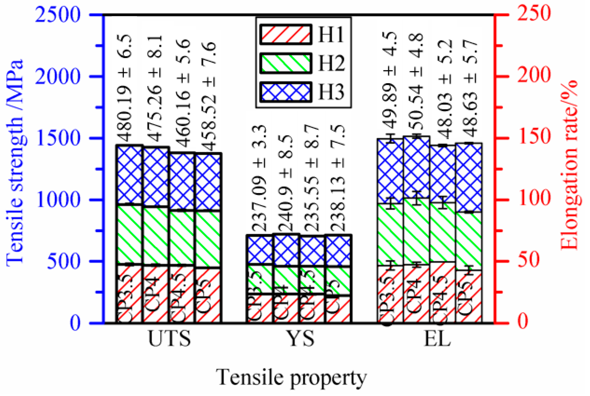
3.4.2. Tensile Properties Analysis

Tensile results were shown in Table 4, compared with the tensile specimens H1, H2 and H3 of CP3.5, CP4, CP4.5 and CP5, the ultimate tensile strength decreased slightly for the increasing thermal accumulation, which led to the coarse grain size, and the toughness was changed irregularly. However, these values are all higher than the standard requirements for the mechanical properties of stainless-steel forgings [27].
As can be seen from the Figure 9, further increasing the wire feeding speed would decrease the horizontal strength and make it lower than the standard of 450 MPa. Combined the molding and performance, 5 m/min is the highest deposition rate.
Microscopic fracture morphology in Figure 10a showed that there was a large number of equiaxed dimples and tear edges, indicating the plastic deformation was sufficient and revealed the characteristics of typical polymerizable dimple ductile fracturing. In the tensile process, the stress was uniformly distributed on the entire fracture surface and the micropores grew uniformly in three directions, forming equiaxial dimples. With the increase of wire feeding speed and scanning speed, and similar heat input, the fracture dimples obviously became smaller and shallower from #CP3.5 to #CP5, indicating that the strength and toughness became worse. This means thermal accumulation not only had a greater impact on the molding, but also decreased the tensile properties. It is possible that the stretching process induced rapid fracturing as a result of the severe heat accumulation, and no sufficient plastic deformation was obtained. Hence, the sample performance was degraded. The second phase particles can be seen in the dimples in all samples, in order to further observe the second phase particles in Figure 10a, energy dispersive spectrometer (EDS) of microscopic fracture of #CP4 was displayed in Figure 10b, it could be seen that the particles were mainly oxidized impurities, and the chemical composition was rich in Si and Mn. Although the deposition process was carried out within the inert gas, the molten pool would still be oxidized after the welding gun travelled away. At a slow strain rate, the particles were preferentially located at the dimple center, which indicated that these particles might be a source of stress concentration and the starting point of micropore formation, and finally became the crack. With the thermal accumulation increased, the grain size was coarse, and oxidation might be severe to produce more secondary phase particles, which might degrade the tensile toughness.

4. Conclusions

This paper investigated process optimization on multilayer morphology of 316L stainless-steel of 1.2 mm diameter during double-wire CMT+P deposition process. The following conclusions were obtained from the test results:
  • The non-synchronous striking and extinguishing arc process adopted in double-wire and double-arc deposition could ensure two arcs starting and ending at the same point, which can improve the deposition morphology.
  • The deposition forming was affected by the interaction of heat input and heat accumulation. The well-formed process of WFS by CMT+P process was in the range of 3–5 m/min. Along with the increase of WFS and TS, although the heat input was unchanged, the interval time between deposition points was shortened, which led to the increase of heat accumulation, and then decreased the height and increased the width of the depositions.
  • The optimized WFS/TS ratio of each 316L welding wire during double-wire CMT+P deposition was about 4.2. The highest deposition rate could reach to 5.4 kg/h when the travelling speed was 120 cm/min.
  • Increasing the wire feeding speed and the scanning speed could improve the deposition rate and keep the thermal input unchanged, but the influence of heat accumulation would result in coarse grain and slight decreasing mechanical property.

Author Contributions

Methodology, W.W. and J.X.; writing—original draft preparation, W.W.; project administration and funding acquisition, J.X.; data curation, W.W. and Z.Z.; writing—review and editing, providing ideas, X.R. and B.X.

Funding

This paper was supported by the National Natural Science Foundation project of China (51875213) and the High-level Leading Talent Introduction Program of Guangdong academy of sciences (grant numbers 2016-GDASRC-0106); Natural Science Foundation of Fujian Province (grant numbers 2018J01503), Longyan Science and Technology Project (grant numbers 2017LY68), The third batch of innovative scientific research team project of Dongguan in 2015 (2017360004004), Guangdong Academy of Science Project(2019GDASLY-0302013).

Conflicts of Interest

The authors declare no conflict of interest.

References

  1. Almangour, B.; Grzesiak, D.; Borkar, T.; Yang, J.M. Densification behavior, microstructural evolution, and mechanical properties of TIC/316L stainless steel nanocomposites fabricated by selective laser melting. Mater. Des. 2018, 138, 119–128. [Google Scholar] [CrossRef]
  2. Harris, M.; Potgieter, J.; Archer, R.; Arif, K.M. In-process thermal treatment of polylactic acid in fused deposition modelling. Mater. Manuf. Processes 2019, 34, 701–713. [Google Scholar] [CrossRef]
  3. Kürnsteiner, P.; Wilms, M.B.; Weisheit, A.; Barriobero-Vila, P.; Jaegle, E.A.; Raabe, D. Massive nanoprecipitation in an Fe-19Ni- x Al maraging steel triggered by the intrinsic heat treatment during laser metal deposition. Acta Mater. 2017, 129, 52–60. [Google Scholar] [CrossRef]
  4. Pere, B.-V.; Joachim, G.; Andreas, S.; Norbert, S.; Jan, H.; Guillermo, R. Peritectic titanium alloys for 3D printing. Nat. Commun. 2018, 9, 3426. [Google Scholar] [CrossRef]
  5. Zhou, K.; Yao, P. Overview of recent advances of process analysis and quality control in resistance spot welding. Mech. Syst. Signal. Pr. 2019, 124, 170–198. [Google Scholar] [CrossRef]
  6. Ding, D.; Pan, Z.; Cuiuri, D.; Li, H. Wire-feed additive manufacturing of metal components: Technologies, developments and future interests. Int. J. Adv. Manuf. Technol. 2015, 81, 465–481. [Google Scholar] [CrossRef]
  7. Pickin, C.G.; Young, K. Evaluation of cold metal transfer (CMT) process for welding aluminium alloy. Sci. Technol. Weld. Join. 2006, 11, 583–585. [Google Scholar] [CrossRef]
  8. Sequeira Almeida, P.M.; Williams, S.W. Innovative process model of Ti-6Al-4V additive layer manufacturing using Cold Metal Transfer (CMT). In Proceedings of the 21st Annual International Solid Freeform Fabrication Symposium, Austin, TX, USA, 1 January 2010. [Google Scholar]
  9. Yao, P.; Zhou, K.; Zhu, Q. Quantitative evaluation method of arc sound spectrum based on sample entropy. Mech. Syst. Signal. Pr. 2017, 92, 379–390. [Google Scholar] [CrossRef]
  10. Su, C.; Chen, X.; Gao, C.; Wang, Y. Effect of heat input on microstructure and mechanical properties of al-mg alloys fabricated by WAAM. Appl. Surf. Sci. 2019, 486, 431–440. [Google Scholar] [CrossRef]
  11. Gomez Ortega, A.; Corona Galvan, L.; Deschaux-Beaume, F.; Mezrag, B.; Rouquette, S. Effect of process parameters on the quality of aluminium alloy Al5Si deposits in wire and arc additive manufacturing using a cold metal transfer process. Sci. Technol. Weld. Join. 2017, 23, 316–332. [Google Scholar] [CrossRef] [Green Version]
  12. Kazanas, P.; Deherkar, P.; Almeida, P.; Lockett, H.; Williams, S. Fabrication of geometrical features using wire and arc additive manufacture. Proc. Inst. Mech. Eng. Part B 2012, 226, 1042–1051. [Google Scholar] [CrossRef]
  13. Xu, X.; Ding, J.; Ganguly, S.; Diao, C.; Williams, S. Preliminary Investigation of Building Strategies of Maraging Steel Bulk Material Using Wire + Arc Additive Manufacture. J. Mater. Eng. Perform. 2018, 28, 594–600. [Google Scholar] [CrossRef]
  14. Cong, B.; Ding, J.; Williams, S. Effect of arc mode in cold metal transfer process on porosity of additively manufactured Al-6.3% Cu alloy. Int. J. Adv. Manuf. Technol. 2015, 76, 1593–1606. [Google Scholar] [CrossRef]
  15. Ayarkwa, K.F.; Williams, S.; Ding, J. Investigation of pulse advance cold metal transfer on aluminium wire arc additive manufacturing. Int. J. Rapid Manuf. 2015, 5, 44–57. [Google Scholar] [CrossRef]
  16. Qi, Z.; Qi, B.; Cong, B.; Sun, H.; Zhao, G.; Ding, J. Microstructure and mechanical properties of wire + arc additively manufactured 2024 aluminum alloy components: As-deposited and post heat-treated. J. Manuf. Processes 2019, 40, 27–36. [Google Scholar] [CrossRef] [Green Version]
  17. Yang, D.; Wang, G.; Zhang, G.A. Comparative study of GMAW- and DE-GMAW-based additive manufacturing techniques: Thermal behavior of the deposition process for thin-walled parts. Int. J. Adv. Manuf. Technol. 2016, 91, 2175–2184. [Google Scholar] [CrossRef]
  18. Zhang, Y.; Li, P.; Chen, Y.; Male, A.T. Automated system for welding-based rapid prototyping. Mechatronics 2002, 12, 37–53. [Google Scholar] [CrossRef]
  19. Wu, W.; Xue, J.; Zhang, Z.; Yao, P. Comparative study of 316L depositions by two welding current processes. Mater. Manuf. Processes 2019, 34, 1502–1508. [Google Scholar] [CrossRef]
  20. Abioye, T.E.; Medrano-Tellez, A.; Farayibi, P.K.; Oke, P.K. Laser metal deposition of multi-track walls of 308LSi stainless steel. Mater. Manuf. Processes 2017, 32, 1660–1666. [Google Scholar] [CrossRef]
  21. Xiong, J. Forming Characteristics in Multi-Layer Single-Bead GMA Additive Manufacturing and Control for Deposition Dimension. Master’s Thesis, Harbin Institute of Technology, Harbin, China, 1 June 2014. [Google Scholar]
  22. Wu, W.; Xue, J.; Wang, L.; Zhang, Z.; Hu, Y.; Dong, C. Forming Process, Microstructure, and Mechanical Properties of Thin-Walled 316L Stainless Steel Using Speed-Cold-Welding Additive Manufacturing. Metals 2019, 9, 109. [Google Scholar] [CrossRef] [Green Version]
  23. Liberini, M.; Astarita, A.; Campatelli, G.; Scippa, A.; Montevecchi, F.; Venturini, G. Selection of optimal process parameters for wire arc additive manufacturing. Procedia CIRP 2017, 62, 470–474. [Google Scholar] [CrossRef]
  24. Xu, X.; Mi, G.; Luo, Y.; Jiang, P.; Shao, X.; Wang, C. Morphologies, microstructures, and mechanical properties of samples produced using laser metal deposition with 316L stainless steel wire. Opt. Lasers Eng. 2017, 94, 1–11. [Google Scholar] [CrossRef]
  25. Iván, T.; Paskual, A.; Álvarez, P.; Suárez, A. Study on Arc Welding Processes for High Deposition Rate Additive Manufacturing. Procedia CIRP 2018, 68, 358–362. [Google Scholar] [CrossRef]
  26. Almangour, B.; Grzesiak, D.; Cheng, J.; Ertas, Y. Thermal behavior of the molten pool, microstructural evolution, and tribological performance during selective laser melting of TIC/316L stainless steel nanocomposites: Experimental and simulation methods. J. Mater. Process. Technol. 2018, 257, 288–301. [Google Scholar] [CrossRef]
  27. ASTM A473-17a, Standard Specification for Stainless Steel Forgings; ASTM International: West Conshohocken, PA, USA, 2017.
Figure 1. Schematic of cold metal transfer (CMT) welding additive manufacturing system.
Metals 09 01334 g001
Figure 2. Current setting curve of arc striking and arc extinguishing.
Metals 09 01334 g002
Figure 3. (a) Single layer forming with different parameters of arcing and extinguishing; (b) continuous forming morphology of 30 layers with the S1 arc striking process.
Metals 09 01334 g003
Figure 4. Schematic diagram of asynchronous arcing and extinguishing.
Metals 09 01334 g004
Figure 5. Unified relationship between wire feeding speed and power of CMT+P.
Metals 09 01334 g005
Figure 6. Influence diagram of wire feeding speed, WFS/TS and heat input on morphology quality during CMT+P multilayer deposition.
Metals 09 01334 g006
Figure 7. Microstructure of the middle section of different depositions.
Metals 09 01334 g007
Figure 8. Microhardness curve of depositions.
Metals 09 01334 g008
Figure 9. Column chart in different properties of CMT+P continuous deposition samples of three horizontal directions (UTS, YS and EL represent ultimate tensile strength, yield strength and elongation rate respectively).
Metals 09 01334 g009
Figure 10. Microscopic fracture and energy dispersive spectrometer (EDS) results. (a) Microfracture morphology and (b) scanning results of the fracture EDS surface of the #CP4 fracture.
Metals 09 01334 g010
Table 1. Experimental parameters of different wire feeding speed (WFS) and traveling speed (TS) in CMT+Pulse (CMT+P) deposition.
SampleDeposition Current I/ADeposition Voltage U/VWire Feed Speed WFS/m·min−1Traveling Speed TS/cm·min−1Heat Input Q/J·mm−1
#CP2.565132.560143.6
#CP37314.1370149.9
#CP3.58015.13.585148.6
#CP49016.24100148.8
#CP4.59616.54.5108149.6
#CP510316.85120147
#CP5.5-13810917.15.5138137.8
#CP5.5-150150126.8
Table 2. Main parameters of arc striking and arc extinguishing in CMT+P welding.
SampleIs/%ts/sSl1/sSl2/ste/sIe/%
#S1 (Default)135off11off45
#S2 (synchronous wires)120111off45
#S3 (synchronous wires)120111.5off50
#S4 (asynchronous wires)120111.5off50
Table 3. Different morphologies of double-arc depositions by the CMT+P process.
SampleHot and Cold Regions of Samples after DepositionDeposition MorphologyHeat Effect on the Back of Substrate
#CP2.5 Metals 09 01334 i001 Metals 09 01334 i002 Metals 09 01334 i003
#CP3 Metals 09 01334 i004 Metals 09 01334 i005 Metals 09 01334 i006
#CP3.5 Metals 09 01334 i007 Metals 09 01334 i008 Metals 09 01334 i009
#CP4 Metals 09 01334 i010 Metals 09 01334 i011 Metals 09 01334 i012
#CP4.5 Metals 09 01334 i013 Metals 09 01334 i014 Metals 09 01334 i015
#CP5 Metals 09 01334 i016 Metals 09 01334 i017 Metals 09 01334 i018
#CP5.5 Metals 09 01334 i019 Metals 09 01334 i020 Metals 09 01334 i021
#CP5.5 Metals 09 01334 i022 Metals 09 01334 i023 Metals 09 01334 i024
Table 4. Tensile results of deposition samples (UTS, YS and EL represent ultimate tensile strength, yield strength and elongation rate respectively).
Tensile resultsSampleH1H2H3Average H
UTS/MPa#CP3.5477.42 ± 9.6485.79 ± 8.4477.35 ± 1.3480.19 ± 6.5
#CP4470.08 ± 9.0472.75 ± 4.1482.93 ± 2.9475.26 ± 8.1
#CP4.5468.87 ± 8.1445.4 ± 8.1466.2 ± 2.5460.16 ± 5.6
#CP5450.39 ± 4.9461.64 ± 6.1463.53 ± 3.1458.52 ± 7.6
YS/MPa#CP3.5236.81 ± 3.7239.95 ± 0.6234.53 ± 1.5237.09 ± 3.3
#CP4236.0 ± 4.5226.9 ± 1.6259.79 ± 5.4240.9 ± 8.5
#CP4.5234.53 ± 6.0226.91 ± 4.6245.23 ± 1.5235.55 ± 8.7
#CP5222.35 ± 1.6236.92 ± 2.3255.13 ± 2.3238.13 ± 7.5
EL/ %#CP3.546.76 ± 3.550.15 ± 4.452.76 ± 3.549.89 ± 4.5
#CP447.31 ± 2.054.06 ± 5.450.26 ± 1.750.54 ± 4.8
#CP4.549.5 ± 048.23 ± 4.846.36 ± 0.848.03 ± 5.2
#CP542.84 ± 3.647.36 ± 0.755.7 ± 0.548.63 ± 5.7

