Article

Influence of Post-Weld Heat Treatments on Microstructure and Mechanical Properties of Laser Beam Welded 2060-T3/2099-T3Al-Li T-Joints

1
State Key Laboratory of Advanced Welding and Joining, Harbin Institute of Technology, Harbin 15001, China
2
Harbin HIT Weld Technology Co., Ltd., Harbin 150060, China
3
Harbin FRP Research Institute, Harbin 150036, China
*
Authors to whom correspondence should be addressed.
Metals 2019, 9(12), 1318; https://doi.org/10.3390/met9121318
Submission received: 21 November 2019 / Revised: 2 December 2019 / Accepted: 4 December 2019 / Published: 6 December 2019

Abstract

:
The durable structure and robustness of T-joints in the panel materials for civil aircraft are a crucial matter of importance. In this work, the impact of the post-weld heat treatments (PWHTs) on the microstructure and mechanical properties of laser beam welded T-joints of 2060-T3/2099-T3 Al-Li alloy was analyzed. Heat-treatment of the laser beam welded T-joints was carried out in two different ways, namely, solution treatment and artificial aging (STAA) at varied duration and only artificial aging (AA) at varied duration. The microstructure and mechanical properties of the heat-treated joints were investigated using metallographic and scanning electron microscopic images, micro-hardness test, and tensile test, respectively. The results showed that, in cases of STAA, the eutectic structures on the grain boundary were partially dissolved via solution treatment (ST), and increased dispersed precipitation of the second phase in matrix resulted in significant dispersion strengthening, as well as enhanced strength and plasticity. In contrast, in the AA process, alloy elements in the matrix continued to segregate towards the grain boundary, resulting in significant grain boundary strengthening, enhanced strength, and decreased plasticity. Additionally, joint fractures were micro-porous aggregation transgranular ones in the fusion zone (FZ). The joints treated by STAA exhibited excellent plasticity compared with those treated by AA. Furthermore, the micro-hardness of welded joints treated by AA was higher than that of those treated by STAA. Indeed, the tensile strength of joints treated by STAA and AA ranged from 405 to 475 MPa, which was 81–95% of the base metal 2060-T8, though the elongation of joints treated by STAA was superior to the counterpart AA.

1. Introduction

Compared with traditional aluminum alloy, Al-Cu-Li alloy is highly promising for applications in the aerospace industry owing to its low density, high elasticity module, high specific stiffness, and high specific strength [1,2,3,4], and 2060/2099 Al-Li alloys are one of the alloys in the Al-Cu-Li alloy system. For each 1% Li added, the density of the aluminum alloy is reduced by 3% and the elastic modulus is increased by 6% [1,2]. The Al-Li alloys 2090 and 2091 contain 1.9–2.6% lithium, which leads to an about 10% lower density and 25% higher specific stiffness than the 2XXX and 7XXX series aluminum alloys [3]. Importantly, Al-Li alloys, especially those consisting of volatile metal elements such as Li and Mg, are readily exposed to solidification cracking and pore defects during fusion welding, resulting in poor weld formation [5,6,7,8]. The evaporation of low boiling point alloy elements and the instability of the keyhole tip are the main reasons for large, irregular-shaped pores [5,6]. The trapping of hydrogen bubbles as the welding pool solidified is the main cause of micro porosity in laser welding of Al-Li alloy [7,8]. During the welding process, the strength of the original welding materials would be softened in the fusion zone (FZ) [9,10,11,12,13]. Ramulu et al. [9] employed tungsten inert gas arc to weld 2090 Al-Li alloy and demonstrated that the strength of joints welded by wires such as 2319/4047/4145 reached up to 60.3% of the strength of the base metal. Also, the maximum strength coefficients of the laser beam welded 2060 Al-Li alloy joint with Al-Mg filler wire [10] and the laser beam welded 2198 Al-Li alloy joint with Al-Si filler wire [11] were 0.63 and 0.65, respectively. The lack of strengthening precipitates related to the matrix precipitation hardening was considered to be the main reason for the hardness/strength reduction in the FZ [12,13]. Ongoing research in this area showed that, compared with traditional fusion welding, a high-energy beam welding can improve the joint strength, which can be further improved by post-weld heat treatment. Ben et al. [14] performed a 24 h post-weld solid treatment (salt bath at 535 °C for 30 min) and AA at 165 °C for 24 h for Al-Cu-Li alloy based joints welded by the electron beam. Specifically, the microstructure of the central FZ was transformed from dendrite crystals to equiaxed crystals. The segregation on the grain boundary was eliminated, and the coefficient of strength was increased from 0.60 to 0.85. Zhuang et al. [15] reported laser beam welding of 1420 Al-Li alloy and achieved joint strength of 75% of that of the base metal. It should be noted that after solid treatment at 460 °C followed by AA at 120 °C for 10 h, the tensile strength of the joint increased to 96% of that of the base metal. So far, the laser beam welding of 2060-T3/2099-T3 Al-Li alloy based T-joints and related scientific testing data are rarely reported [16,17]. In this study, laser beam welding was used for 2060-T3/2099-T3 Al-Li alloy based T-joints. After welding, two different heat treatments, namely, solution treatment and artificial aging (STAA), and artificial ageing (AA), of the welded T-joints were carried out. STAA was a combination of the solution treatment at 500 °C for 1 h afterward artificial aging at 165 °C for the duration of 10 h, 20 h, and 30 h. In contrast, AA at 165 °C for 10 h, 20 h, and 30 h was carried after the laser beam welding. Afterwards, the microstructures and mechanical properties of joints treated by STAA and AA were investigated and a comparative analysis was done to understand the impact of post-weld heat treatment on the performance of laser beam welded Al-Li alloyed T-joints. Thus, this scientific work would provide insight into technical support for laser beam welding of Al-Li alloys.

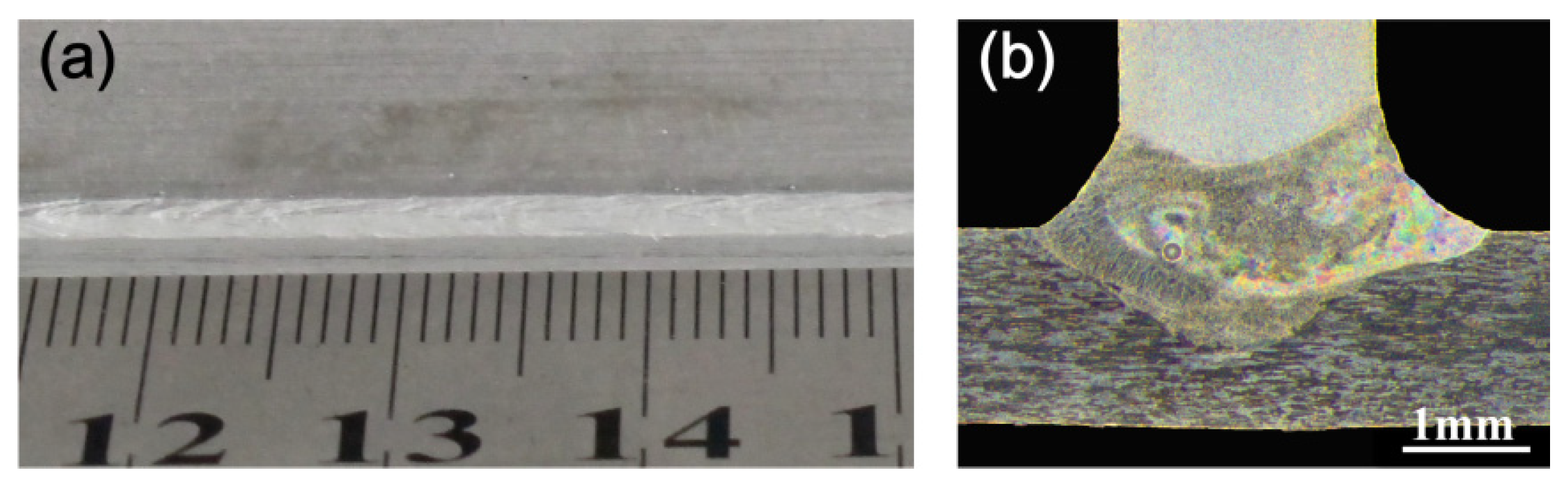
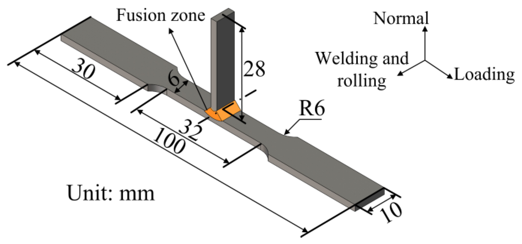
2. Materials and Methods

The testing material used was the commercially available panel material for civil aircraft fuselage. The skin material and the stringer material were 2060-T3Al-Li alloy rolled sheet and extruded 2099-T3Al-Li alloy, respectively. The dimension specifications of the rolled sheet of skin and stringer material were 400 mm (length) × 130 mm (width) × 1.5 mm (thickness) and 400 mm (length) × 2.0 mm (thickness), respectively. The filler wire was ER4047 wire with a diameter of 1.2 mm and related chemical compositions of the base metal 2060-T8 and filler wire are shown in Table 1. Before testing, NaOH was utilized to remove oxide films from the test materials, followed by neutralization by acid HNO3, and then washed by clean water and dried well.
The applied welding method was double-sided laser synchronous welding (fiber laser = YLS-5000 and YLS-10000, IPG photonics corp., Germany). Protecting gas nozzles and wire feeding devices (wire-feeder = KD-4010, Frontius International GmbH, Austria) were arranged on both sides at an appropriate angle to each other. The welding equipment was fixed on the two six-axis robot arms (KR-16W, KUKA Robot Group, Germany) and the stringer was vertically pressed on the skin by an assembly technology clamp. The laser beam, the wire-feeder, and the protecting gas nozzle were located on the same plane. The angle (α) between the laser beam and skin was fixed at 22°, the angle (β) between the wire-feeder and the welding direction and the angle (θ) between the protecting gas nozzle and the welding direction were fixed at 20° each. As shown in Figure 1, the wire-feeder and the protecting gas nozzle were positioned at either side beyond the end of the welding site, respectively. The direction of welding and the plate rolling was consistent during the welding process.
A large number of welding process tests of laser-welded 2060-T8 and 2099-T83 Al-Li alloy T-joints had been carried out to explore and optimize process parameters in the early stage [17]. In this research, the same welding system was applied and several test specimens were welded with different welding process parameters (i.e., laser power and wire feeding rate). The welding process parameters were optimized as shown in Table 2 and four of the test specimens under the same welding process parameters were selected for post-weld heat treatment (PWHT) and subsequent tests. The selected standard was that the weld was well formed and no pores or cracks were formed on the welding surface, as shown in Figure 2.
Before welding, the testing material was at the T3 heat treatment state and could not be used without post-weld heat treatment. The strength of the T-joints after post-weld heat treatments was compared with that of the base metal 2060-T8 (501 MPa tensile strength), which can be directly used in the riveted structure of the aircraft fuselage. The incorporated two different post-weld heat treatment process were as follows: first as STAA: post-weld ST at 500 °C for 1 h followed by water cooling up to room temperature, and thereafter the AA process at 165 °C for the varying duration of 10 h, 20 h, and 30 h, followed by natural cooling up to room temperature in the furnace; second as AA: post-weld AA process at 165 °C for 10 h, 20 h, and 30 h, followed by natural cooling up to room temperature in the furnace. The process parameters of AA in these two methods were consistent. The process parameters of PWHT and the number of samples for tests under these PWHT parameters are shown in Table 3. The sample for metallographic inspection was first sanded and then polished nicely. Also, a corrosion-free cleaning in the Keller’s reagent (configuration ratio: 1 mL HF, 1.5 mL HCl, 2.5 mL HNO3, 95 mL water) for 20 s was done before it underwent testing. The microstructures of the welded joints and joints after post-weld heat treatment were investigated using optical microscope (OLYMPUS-GX71, Japan) and scanning electron microscope (SEM, FEI Quanta 200FEG, America). Further, a micro-hardness test and tensile test were performed on these T-joints after post-weld heat treatments. The micro-hardness test and the tensile test were done using a Vickers micro-hardness meter (HXD-1000TM, China) with a 200 g load for 10 s and an electronic universal testing machine (INSTRON-5569, America), respectively. The specimens for the tensile test were prepared using ASTM E 8M-04 and the tensile rate was 2 mm/min throughout the testing. Figure 3 shows the dimensions of tensile samples. In this work, for each heat treatment parameter, three samples were involved for the tensile test and the average of these values was considered as the tensile strength of a particular one.

3. Results and Discussion

In this section, tensile strength, micro-hardness, and microstructure of the welded T-joints produced under the different parameter will be studied to optimize the post-weld heat treatment method. The tensile fracture, micro-hardness, and microstructure of the welded T-joints heat-treated by STAA (165 °C for 20 h) and AA (165 °C for 20 h) were recorded for a comparable analysis of the joint strengthening effects, which was caused by the heat treatment of STAA and AA, distinctively.

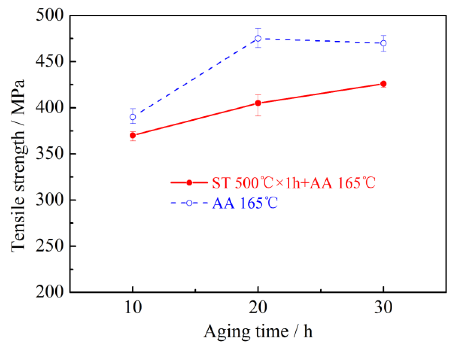
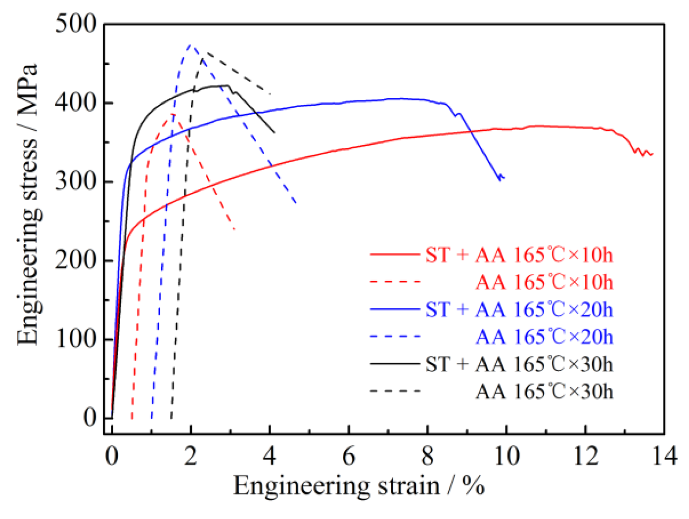
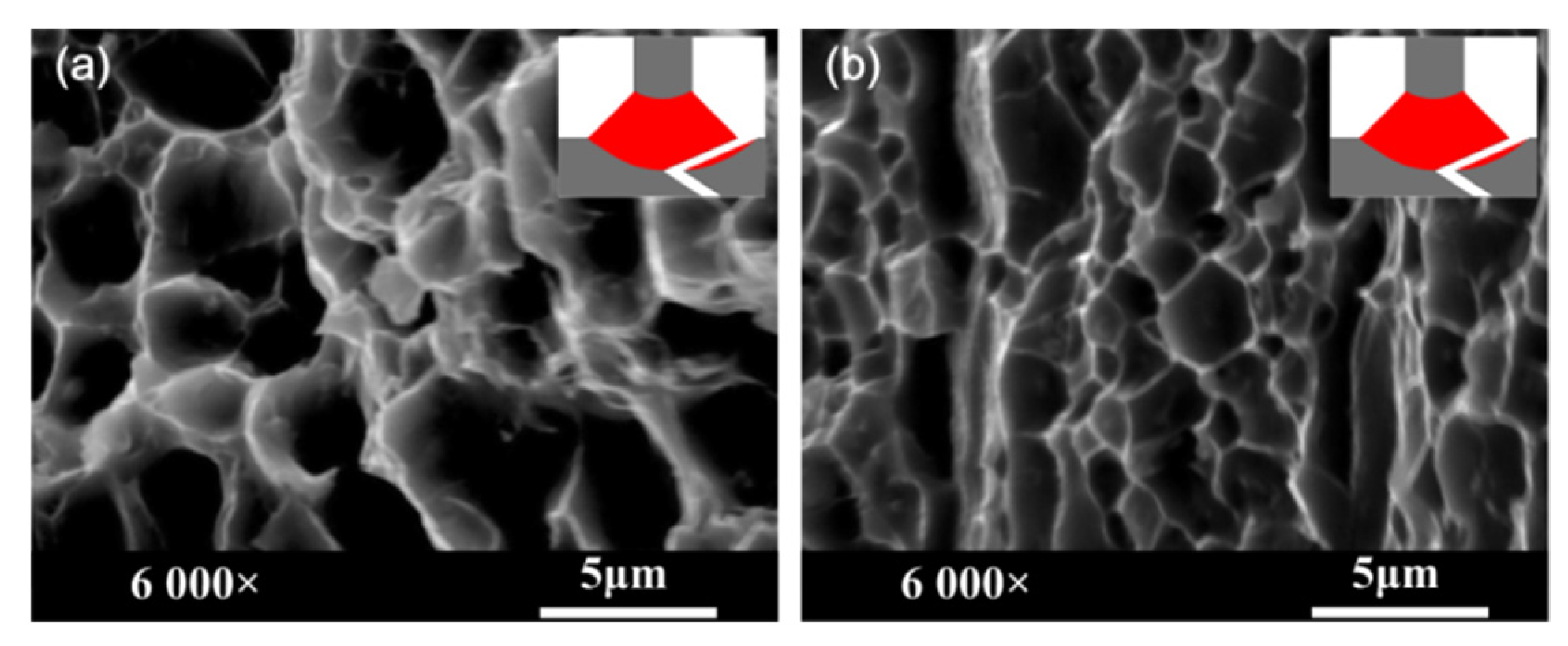
3.1. Effects of Post-Weld Heat Treatment on Tensile Properties

The tensile strength and elongation of the T-joints produced under different heat treatment parameters are shown in Table 4. The trend of the tensile strength as a function of aging period is shown in Figure 4. The stress-strain curves of the T-joints treated by STAA and AA at different conditions of heat treatment, respectively, are shown in Figure 5. The STAA treated samples exhibited the increased tensile strength and slightly decreased elongation as the aging period was increased. Thus, the joints heat-treated by STAA did not reach the overaged condition. On the other side, the tensile strength was increased initially and then a decrement was noticed in the joints heat-treated by AA. The joint heat-treated by AA demonstrated the under aged, peak-aged, and overaged conditions. The strength coefficient of the welded T-joints under four different heat treatment parameters, namely, STAA at 165 °C for 20 h, STAA at 165 °C for 30 h, AA at 165 °C for 20 h, and AA at 165 °C for 30 h, exceeded 80%, which satisfies the strength requirement for the purpose of industrial applications. Notably, joints treated by AA alone exhibited elongations less than 1%, while the ductility of the joints after solution treatment was considerably higher than that before the treatment. In terms of the mechanical properties like strength and toughness, the welded T-joints were treated by two heat treatments, namely, STAA at 165 °C for 20 h and STAA at 165 °C for 30 h, which are preferably suitable for industrial applications.
Figure 6 illustrates the fractured surface of the welded T-joints treated by STAA at 165 °C for 20 h and AA at 165 °C for 20 h. As can be seen, fractures in all the samples occurred firstly near the skin side in the FZ, which is considered the weak area of the welded joint. Additionally, various dimples were observed on the fractured section, which also consisted of the second phase particles or related traces. Hence, fractures were transgranular ones with micro-porous aggregation. It should be noted that the dimples on the fractured joints that were heat-treated by STAA at 165 °C for 20 h exhibited large depth and size, and thus an excellent demonstration of plasticity in the both microscopic and macroscopic aspects.

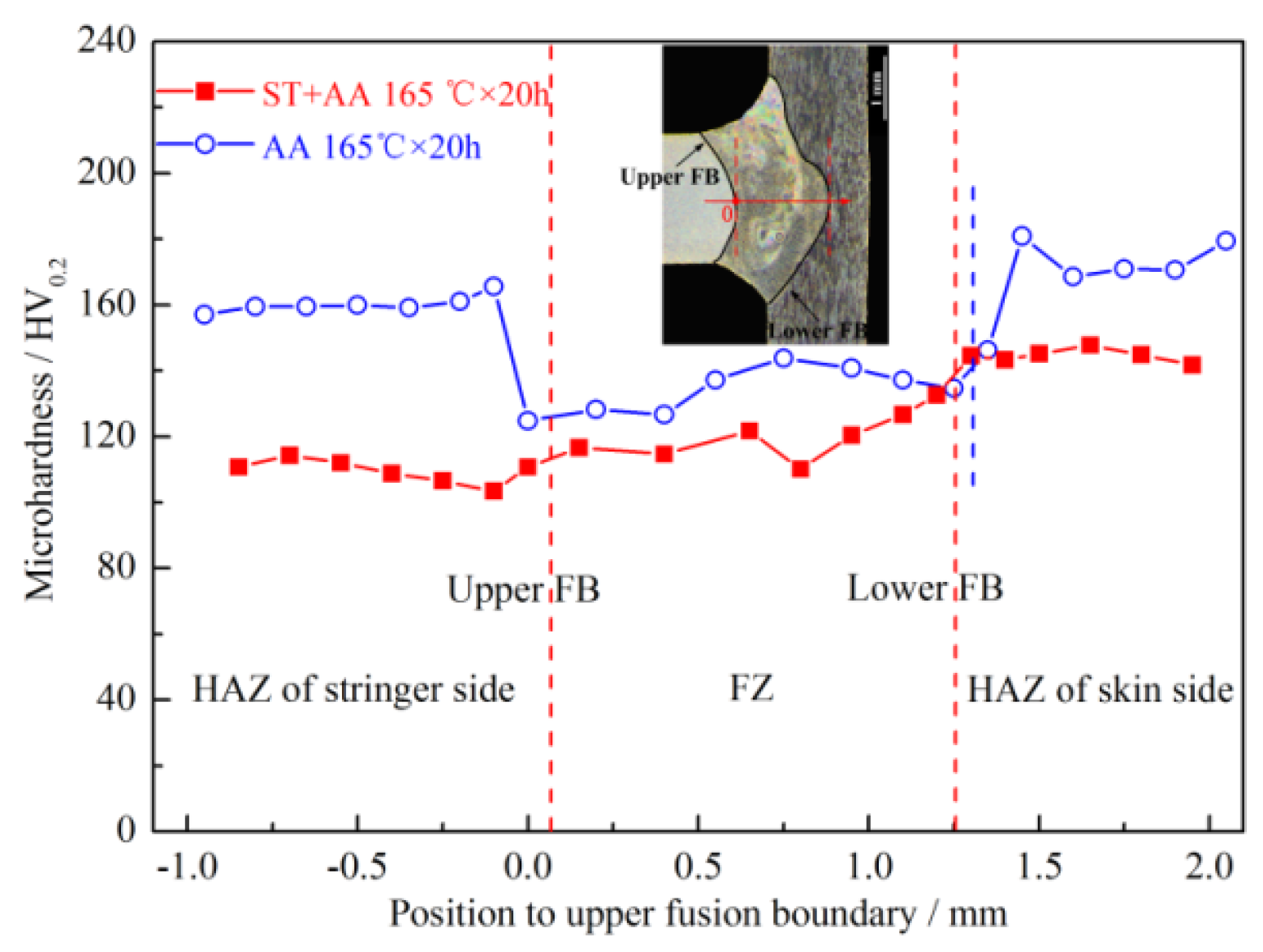
3.2. Effects of Post-Weld Heat Treatment on Micro-Hardness

Micro-hardness analysis was performed on the metallographic cross-sections of the heat-treated by STAA at 165 °C for 20 h and AA at 165 °C for 20 h welded T-joints, respectively. The testing sites were arranged on the stringer, upper fusion boundary (FB), central FZ, lower FB, and skin, as can be seen in Figure 7. The results demonstrated that the average micro-hardness of the welded T-joints heat-treated by STAA was achieved as 119.2 HV, 144.6 HV, and 109.3 HV at the central FZ, skin, and stringer, respectively. On the similar testing sites, the average micro-hardness was achieved as 134.2 HV, 169.5 HV, and 160.2 HV in the counterpart AA heat-treated joints, respectively. The micro-hardness of joints treated by AA exceeded that of joints treated by STAA. It is worth noting that the Al-Li alloy 2060/2099 is a typical precipitate strengthened alloy [16,17], and laser beam welding consists of rapid heating and cooling, which leaves insufficient time for precipitation of alloy elements in the FZ [18]. As a result, the generation of precipitation phases was reduced compared with that of the base materials and the FZ remained in an under aged condition, resulting in ineffective aging strengthening and reduced micro-hardness at the FZ [18]. Therefore, the micro-hardness of the heat-affected zone (HAZ) degraded as a consequence of AA. The enhancement of the micro-hardness of joints treated by post-weld heat treatment can be attributed to the microstructure transition caused by AA, which will be discussed in the following sections. The micro-hardness of the joint treated by STAA was larger than that of the joint treated by AA. For the STAA and AA methods, the aging temperature and time were identical, but STAA included the solution treatment. This can be attributed to the fact that a small amount of precipitation phases, such as the Al2Cu phase [19] in the FZ, and a part of precipitation phases, such as the Al7Cu4Li phase [20] in the HAZ, were re-dissolved into the matrix, which were induced by solution treatment.

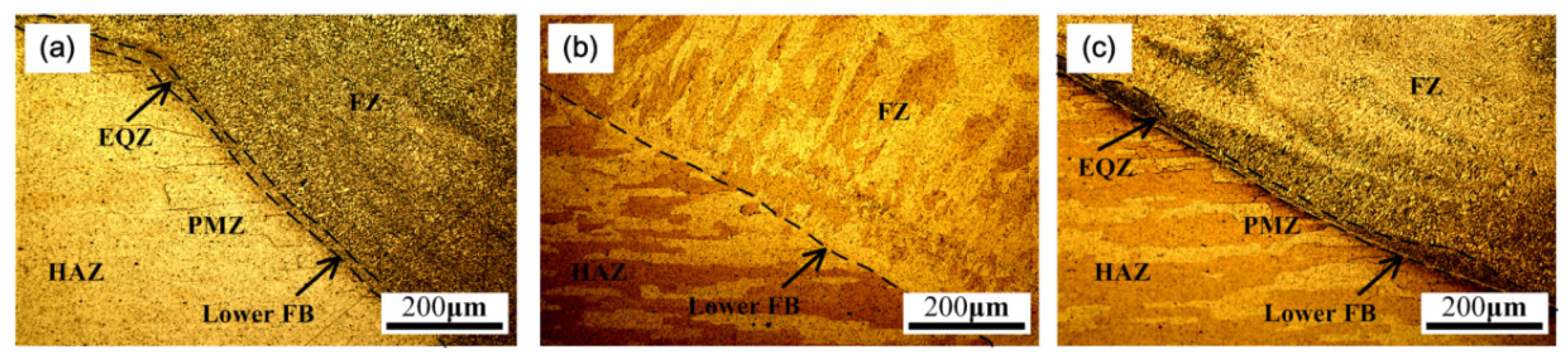
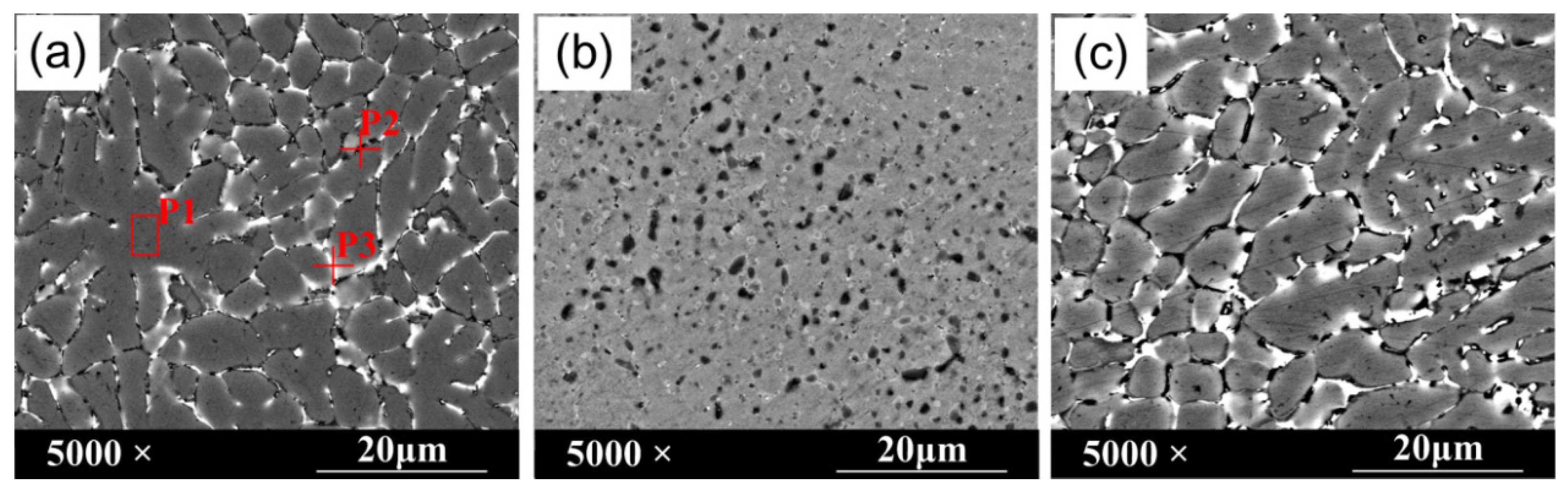
3.3. Effects of Post-Weld Heat Treatment on Joint Microstructures

Figure 8 shows the metallographic structure of the parts that are near to the lower FB of the 2060-T3/2099-T3 Al-Li alloy T-joints heat-treated by STAA at 165 °C for 20 h and AA at 165 °C for 20 h, respectively. As shown in Figure 8a, the microstructure of laser beam welded joints can be divided into the base metal, HAZ, partially melted zone (PMZ), equiaxed zone (EQZ), and FZ. Owing to the melting and solidification of the grain boundary with a low melting point inside the PMZ during the welding, alloy elements at the grain boundary are more prone to segregation and aggregation as compared with those in grains. That is why the grain boundaries were more susceptible to corrosion by Keller’s reagent and also appeared in the metallographic picture. The EQZ is a unique microstructure of the Al-Li alloy welded joint. First, nuclei formation was triggered in the fine-grain region with high melting point particles of Al3Zr as the nuclei, resulting in fine microstructures. The thickness of the fine-grain zone was about 20 μm. In FZ, the crystallization rate, size of the constitutional undercooled zone, and nucleation speed were decreased as the temperature of the molten pool was increased. Then, the growth of the metal at the molten pool around EQZ was limited along the direction that is perpendicular to the wall of the molten pool. Also, the fastest heat dissipation rate assisted the formation of the dendrite structure in FZ as a consequence of segregation of alloy elements. As shown in Figure 8b, the lower FB, FZ dendrite structure, PMZ, and EQZ were removed after solution treatment. This can be attributed to the solid solution of alloy elements in the FZ dendrite structure and segregated alloy elements on PMZ and EQZ grain boundary into the matrix after solution treatment. As shown in Figure 8c, the lower FB of the joint and the dendrite structure of FZ, PMZ, and EQZ were observed under a low-resolution microscope. In other words, the microstructure in this case was consistent with that at the welding state.
The micro-hardness of the FZ was lower than that of the heat-affected zone on the skin side. The section of the tensile fracture was close to the lower FB in the FZ. Hence, microstructure of the FZ was investigated carefully. Backscatter electron (BSE) scanning and energy spectrum analysis were performed on the T-joints to analyze the effects of the post-weld heat treatment on the FZ. Figure 9 shows BSE images of microstructure of the FZ before and after post-weld heat treatment. Table 5 shows the mass fraction and atomic fraction of alloy elements. As can be seen in Figure 9a, at the different positions, there are no traces of Si in the base metal, while the primary alloy element of the filler wire was Si. According to energy spectra of P1, P2, and P3, black and white phases mainly contain Si and Cu, respectively. Specifically, the grain strengthening phases in the FZ were mainly composed of the T phase with fiber-like distribution (AlLiSi, black phase in BSE image), the Cu-contained eutectic phases (white phase in BSE image), and some dispersed precipitated phases [17].
As shown in Figure 9b, for the welded joints heat-treated by STAA, the Cu-contained eutectic phases at grain boundary disappeared; however, T phases were grown into spheroidized form at the grain boundary. It transformed the distribution of grain boundary from a continuous phase to a discontinuous one. The dispersed precipitation of the second phase from the matrix was increased. From the macroscopic aspect, the distribution of strengthening phases in the FZ changed from a continuous one to a dispersed one, resulting into enhanced dispersion strengthening and reduced grain boundary strengthening. This is mainly attributed to the acceleration of atomic diffusion by solution treatment, resulted in diffusion of alloy elements at the grain boundary to the matrix, homogenization of the matrix, elimination of composition segregation of the dendrite crystals, and generation of supersaturated solid solutions. Further, AA after solution treatment induces the precipitation decomposition of the supersaturated solid-solution and re-dispersion and/or re-precipitation of alloy elements in the FZ from the super-satisfied solution as second phase particles. It enhanced the dispersion strengthening, substantially strength, hardness, and plasticity of the welded T-joints.
As shown in Figure 9c, for the welded joints heat-treated by AA, T phases, and Cu-contained eutectic phase at grain boundary were coarse owing to the absence of solution treatment assisted diffusion of alloy elements to the matrix. It initiated the diffusion of alloy elements from the matrix phase to the grain boundary, resulting in reduced dispersion strengthening and enhanced grain boundary strengthening. This is attributed to the fact that AA heat treatment after laser beam welding stimulates the continuous segregation of alloy elements in the FZ towards the grain boundary of the dendrite crystals. The severe segregations at the grain boundary lead to the continuous, coarse, and dense grain boundary, and thus enhanced grain boundary strengthening, improved strength, and hardness of the joint, as well as reduced plasticity of the joint, have resulted.

4. Conclusions

In summary, laser beam welded 2060-T3/2099-T3 Al-Li alloy based T-joints were heat-treated by STAA and AA after welding at various process parameters. The results demonstrated that the tensile strengths of joints treated by STAA at 165 °C for 20 h and 30 h and AA after welding at 165 °C for 20 h and 30 h were 405–475 MPa, which is 81–95% of the strength of the base metal 2060-T8. The elongations of joints heat-treated by STAA were superior to those treated by AA. The enhanced performance of T-joints after STAA was analyzed from the perspective of microstructure. The results demonstrated that the distribution of the strengthening phases at the grain boundary changed from a continuous one to a dispersed one. The eutectic structures on the grain boundary were partially spheroidized and partially dissolved in the matrix via solution treatment. Although dispersed precipitation of the second phase from the matrix was increased, it resulted in significant dispersion strengthening and enhanced strength and plasticity. In the AA process, segregation of the alloy elements in the FZ of matrix to grain boundary was continued. The strengthening phases on the grain boundary were continuous, coarse, and dense, which resulted in enhanced grain boundary strengthening, and thus improved strength and decreased plasticity. The post-weld STAA treatment (ST 500 °C × 1 h + AA 165 °C × 20 h or 30 h) is an efficient and optimized condition to improve the strength and toughness of 2060-T3/2099-T3 Al-Li alloy based T-joints. This approach can be used to enhance the overall performances of the T-joints for industrial application.

Author Contributions

Conceptualization, Y.C. and W.T.; formal analysis, Y.Z.; investigation, Y.Z. and Y.C.; resources, Y.C. and W.T.; data curation, Y.Z.; writing—original draft preparation, Y.Z. and T.N.; writing—review and editing, Y.C. and W.T.; visualization, Y.Z.; supervision, Y.C. and W.T.; project administration, Y.C., W.T., and Z.L.; funding acquisition, Y.C. and Z.Y.

Funding

This research was funded by the National Key Research and Development Program of China, grant number No.2017YFB1301600.

Acknowledgments

The authors would like to gratefully acknowledge the National Engineering Research Center of Commercial Aircraft Manufacturing for providing the Al-Li alloys that would be used in fuselage panels.

Conflicts of Interest

No conflict of interest exists in the submission of this manuscript, and the manuscript is approved by all authors for publication. All authors would like to declare that none of the material in the paper has been published or is under consideration for publication elsewhere.

References

  1. Polmear, I.J. Aluminum alloys—A century of age hardening. Mater. Forum 2004, 28, 1–14. [Google Scholar]
  2. Roberto, J.R. Fabrication methods to manufacture isotropic Al-Li alloys and products for space and aerospace applications. Mater. Sci. Eng. A 1998, 257, 100–107. [Google Scholar]
  3. Dursun, T.; Soutis, C. Recent developments in advanced aircraft aluminum alloys. Mater. Des. 2014, 56, 862–871. [Google Scholar] [CrossRef]
  4. Gupta, R.K.; Nayanb, N.; Nagasireesha, G.; Sharma, S.C. Development and characterization of Al-Li alloys. Mater. Sci. Eng. A 2006, 420, 228–234. [Google Scholar] [CrossRef]
  5. Wang, W.; Xu, G.Y.; Duan, A.Q.; Wang, X.Y.; Ba, R.Z. Porosity formation mechanism in laser welding 1420 Al-Li alloy. Trans. China Weld. Inst. 2005, 26, 59–62. [Google Scholar]
  6. Xiao, R.S.; Yang, W.X.; Chen, K. Nd: YAG laser welding of 1420 aluminum-lithium alloy. Chin. J. Lasers 2007, 34, 239–241. [Google Scholar]
  7. Canaby, J.L.; Blazy, F.; Fries, J.F.; Traverse, J.P. Effects of high temperature surface reactions of aluminum-lithium alloy on the porosity of welded areas. Mater. Sci. Eng. A 1991, 136, 131–139. [Google Scholar] [CrossRef]
  8. Huang, M.; Li, G.A.; Zhang, K.; Feng, Z.H. Laser welding characteristics of 2A97 Al-Li alloy. Trans. China Weld. Inst. 2014, 35, 100–104. [Google Scholar]
  9. Ramulu, M.; Rubbert, M.P. Gas tungsten arc welding of Al-Li-Cu alloy 2090. Weld. Res. Suppl. 1990, 109s–114s. [Google Scholar]
  10. Zhang, X.Y.; Yang, W.X.; Xiao, R.S. Microstructure and mechanical properties of laser beam welded Al-Li alloy 2060 with Al-Mg filler wire. Mater. Des. 2015, 88, 446–450. [Google Scholar] [CrossRef]
  11. Lin, K.L.; Yang, W.X.; Lv, J.X.; Xiao, R.S. Laser beam welding study of 2198-T851 aluminum-lithium alloy. Chin. J. Lasers 2014, 41. [Google Scholar] [CrossRef]
  12. Zhang, X.Y.; Huang, T.; Yang, W.X.; Xiao, R.S.; Liu, Z.; Li, L. Microstructure and mechanical properties of laser beam-weldedAA2060 Al-Li alloy. J. Mater. Process. Technol. 2016, 237, 301–308. [Google Scholar] [CrossRef]
  13. Cao, X.; Wallace, W.; Immarigeon, J.P.; Poon, C. Research and progress in laser welding of wrought aluminum alloys. II. metallurgical microstructures, defects, and mechanical properties. Mater. Manuf. Processes 2003, 18, 23–49. [Google Scholar] [CrossRef]
  14. Ben, H.F. Electron Beam Welding Technology of Al-Cu-Li Alloy and Microstructure and Properties of Welded Joint. Master’s Thesis, Nanjing University of Aeronautics and Astronautics, Nanjing, China, 2015. [Google Scholar]
  15. Zhuang, L. Research on the Micro Structures and Properties of Laser Welding Joint for 1420 Aluminum-Lithium Alloy. Master’s Thesis, Dalian Jiaotong University, Dalian, China, 2005. [Google Scholar]
  16. An, N.; Zhang, X.Y.; Wang, Q.M.; Yang, W.X.; Xiao, R.S. Fiber laser welding of 2060 aluminum-lithium alloy with filler wire. Chin. J. Lasers 2014, 41. [Google Scholar] [CrossRef]
  17. Zhang, Y.L.; Tao, W.; Chen, Y.B. Process, microstructures and mechanical properties of double-sided fiber laser beam welded T-joints of aluminum-lithium alloys 2060 and 2099. In Proceedings of the ICALEO 2015—The 34th International Congress on Applications of Laser & Electro-optics, Atlanta, GA, USA, 18–22 October 2015; pp. 437–445. [Google Scholar]
  18. Ning, J.; Zhang, L.J.; Bai, Q.L.; Yin, X.Q.; Niu, J.; Zhang, J.X. Comparison of the microstructure and mechanical performance of 2A97 Al-Li alloy joints between autogenous and non-autogenous laser welding. Mater. Des. 2017, 120, 144–156. [Google Scholar] [CrossRef]
  19. Han, B.; Chen, Y.B.; Tao, W.; Li, H.; Li, L.Q. Microstructural evolution and interfacial crack corrosion behavior of double-sided laser beam welded 2060/2099 Al-Li alloys T-joints. Mater. Des. 2017, 135, 353–365. [Google Scholar] [CrossRef]
  20. Chen, D.L.; Chaturvedi, M.C. Effects of welding and weld heat-affected zone simulation on the microstructure and mechanical behavior of a 2195 aluminum-lithium alloy. Metall. Mater. Trans. A 2001, 32, 2729–2741. [Google Scholar] [CrossRef]
Figure 1. Schematic of the laser beam welding.
Metals 09 01318 g001
Figure 2. The photographs of the T-joint: (a) one-sided weld surface appearance and (b) metallographic photograph at the cross-section of the T-joint.
Metals 09 01318 g002
Figure 3. Dimensions of tensile samples.
Metals 09 01318 g003
Figure 4. Trends of tensile strength as a function of aging time. ST, solution treatment; AA, artificial aging.
Metals 09 01318 g004
Figure 5. Engineering stress-strain curve.
Metals 09 01318 g005
Figure 6. Tensile fracture morphology of the fusion zone (FZ) for the joints treated by (a) STAA at 165 °C for 20 h and (b) AA at 165 °C for 20 h.
Metals 09 01318 g006
Figure 7. Micro-hardness distribution. HAZ, heat-affected zone; FB, fusion boundary; FZ, fusion zone.
Metals 09 01318 g007
Figure 8. Metallographic structure near the lower FB of Al-Li alloy T-joints: (a) welding state, (b) STAA at 165 °C for 20 h, and (c) AA at 165 °C for 20 h. PMZ, partially melted zone; EQZ, equiaxed zone.
Metals 09 01318 g008
Figure 9. Backscatter electron (BSE) image of the FZ for Al-Li alloy T-joints: (a) welding state, (b) STAA at 165 °C for 20 h, and (c) AA at 165 °C for 20 h.
Metals 09 01318 g009
Table 1. Chemical compositions of the base metal and the filler wire (wt.%).
MaterialsCuLiSiMgZnMnZrAgFeAl
2060-T33.900.800.020.700.320.290.100.340.02Bal.
2099-T32.521.87-0.501.190.310.08--Bal.
ER4047<0.001-11.520.010.0010.01--0.20Bal.
Table 2. Parameters of laser beam welding.
Welding ParametersValues
Laser power (P) 2800 W
Welding speed (v) 10 m/min
Wire feeding rate (v’) 3.6 m/min
Incident beam angle (α) 22°
Wire feeding angle (β) 20°
Protecting gas angle (θ) 20°
Focal positionSpecimen surface
Protecting gasAr
Protecting gas flow rate15 L/min
Table 3. Process parameters of post-weld heat treatment (PWHT). ST, solution treatment; AA, artificial aging; SEM, scanning electron microscope.
No.PWHTNumber of Samples
Metallographic Inspection, SEM Observation, and Micro-Hardness TestTensile Test
1-1ST at 500 °C for 1 h and AA at 165 °C for 10 h23
1-2ST at 500 °C for 1 h and AA at 165 °C for 20 h23
1-3ST at 500 °C for 1 h and AA at 165 °C for 30 h23
2-1AA at 165 °C for 10 h23
2-2AA at 165 °C for 20 h23
2-3AA at 165 °C for 30 h23
Table 4. Tensile strengths, strength coefficients, and elongations of joints under different heat treatment parameters.
PWHTTensile StrengthStrength Coefficient *Elongation
ST at 500 °C for 1 h and AA at 165 °C for 10 h370 MPa74%11–13%
ST at 500 °C for 1 h and AA at 165 °C for 20 h405 MPa81%5–8%
ST at 500 °C for 1 h and AA at 165 °C for 30 h421 MPa85%2–5%
AA at 165 °C for 10 h390 MPa78%<1%
AA at 165 °C for 20 h475 MPa95%<1%
AA at 165 °C for 30 h470 MPa94%<1%
* Strength coefficient is the ratio between the tensile strength of the joint and that of the 2060-T8 base metal.
Table 5. Mass fractions and atomic fractions of alloy elements in different positions of the fusion zone (FZ).
ElementCuSiMgAl
wt.%at.%wt.%at.%wt.%at.%wt.%at.%
P12.601.101.541.511.021.1694.8496.23
P22.030.8813.6613.380.810.9383.5084.82
P311.645.290.680.701.722.0785.9691.94

