Effect of Salt Bath Nitrocarburizing and Post-Oxidation on Static and Fatigue Behaviours of a Construction Steel


Abstract
:1. Introduction
2. Materials and Methods
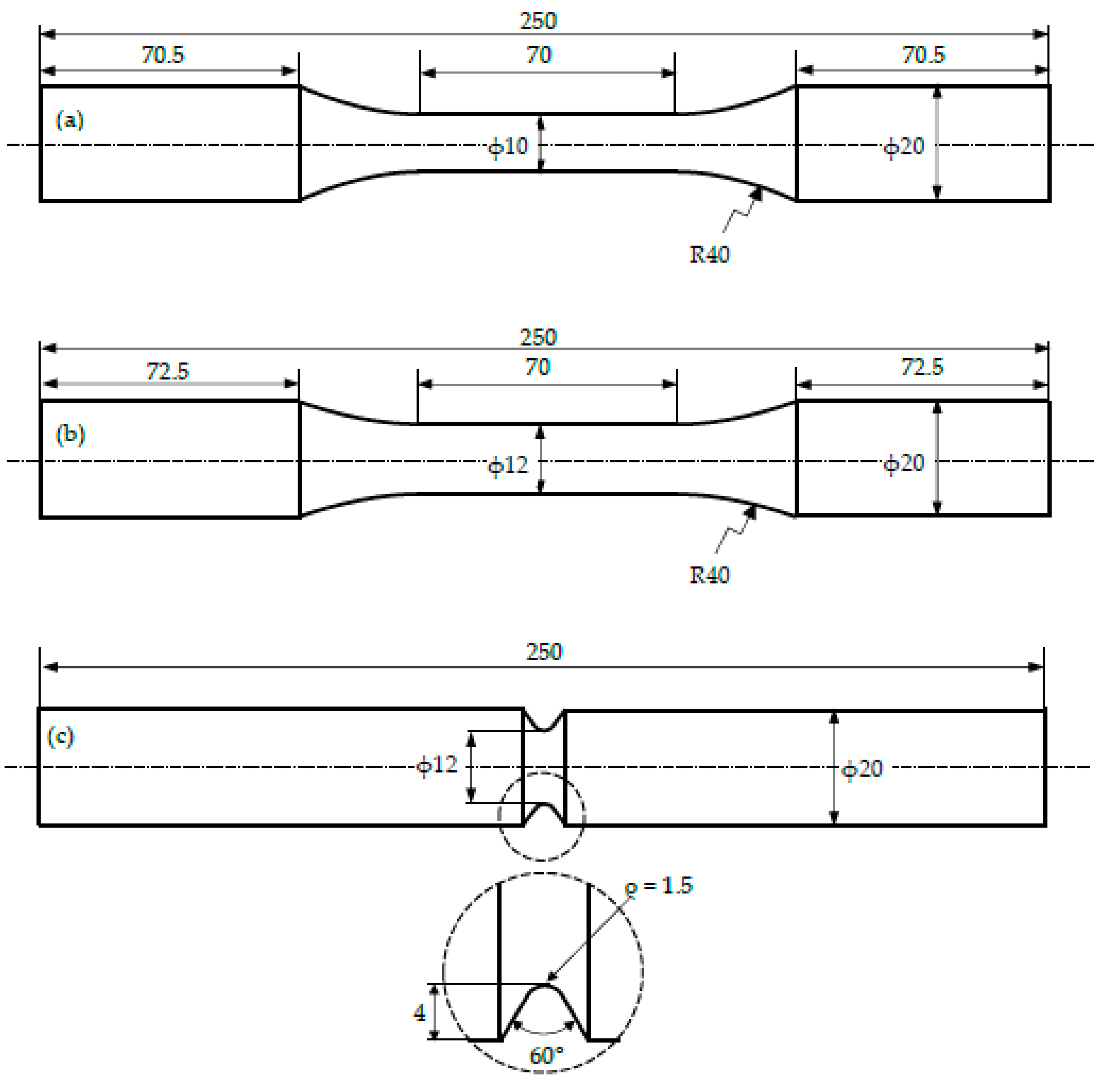
2.1. Materials and Specimen Geometries
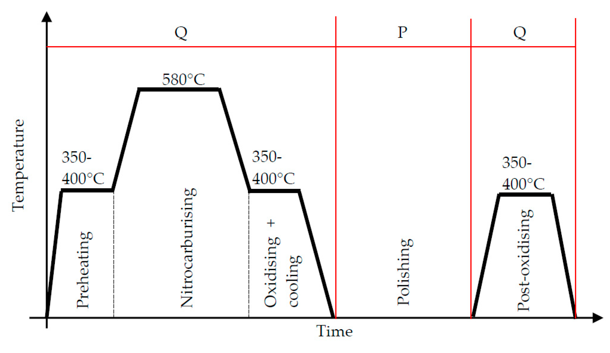
2.2. Salt Bath Nitrocarburization and Post-Oxidation (QPQ) Heat Treatment
2.3. Microstructure and Microhardness
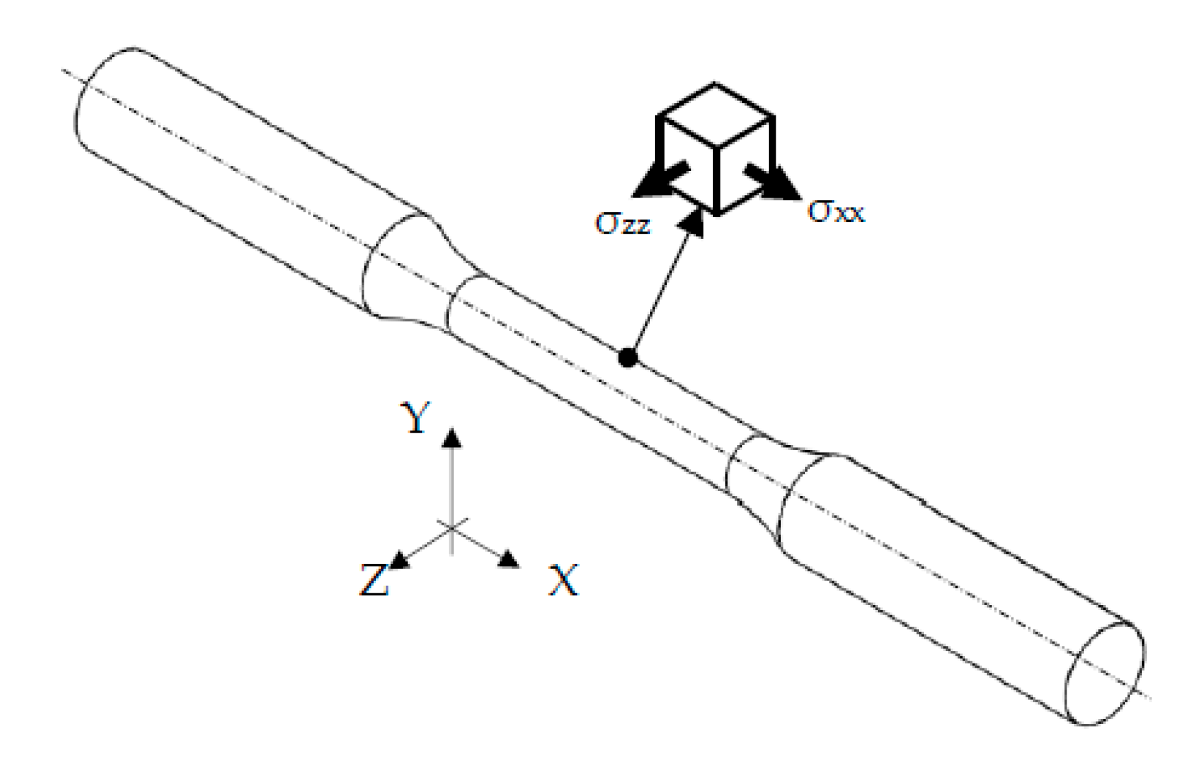
2.4. Surface Residual Stresses
2.5. Static and Fatigue Experiments
3. Results
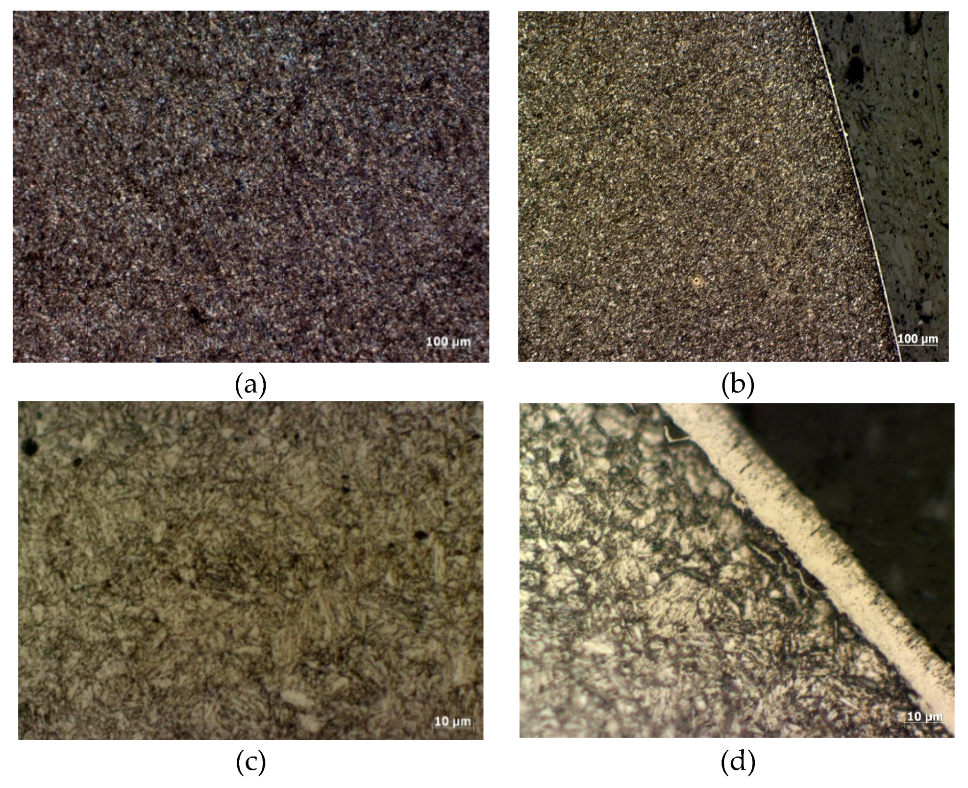
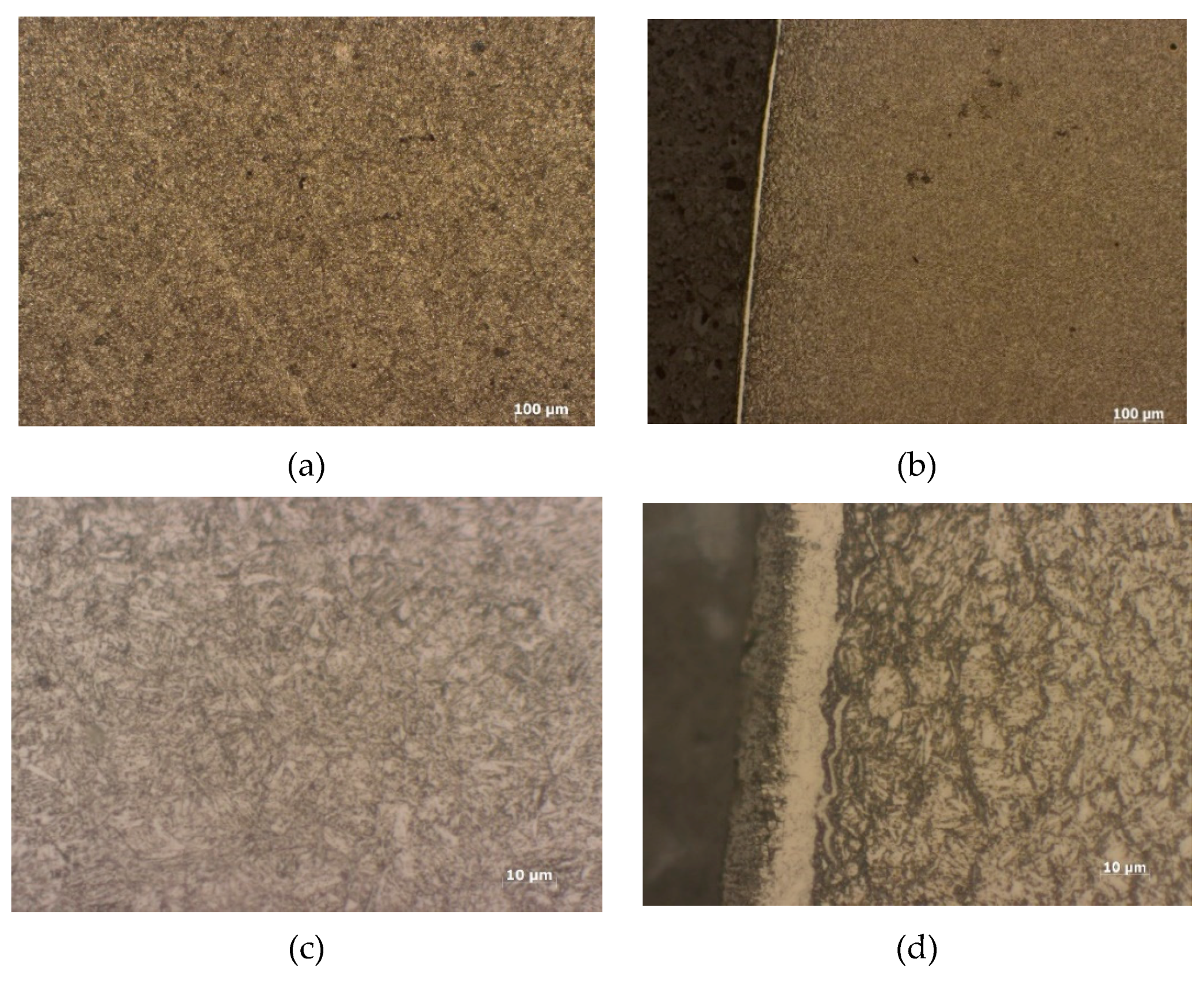
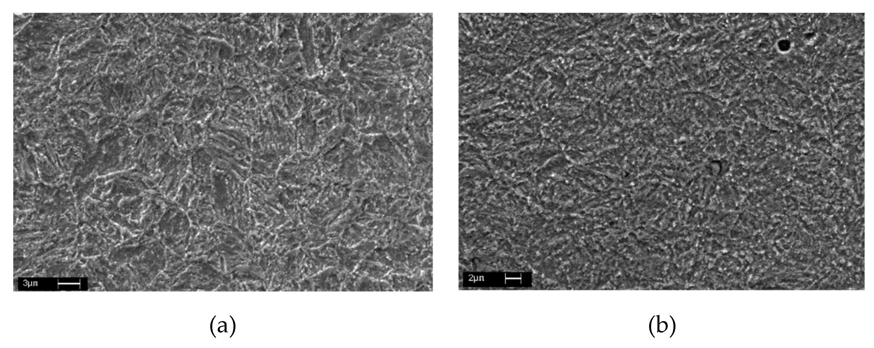
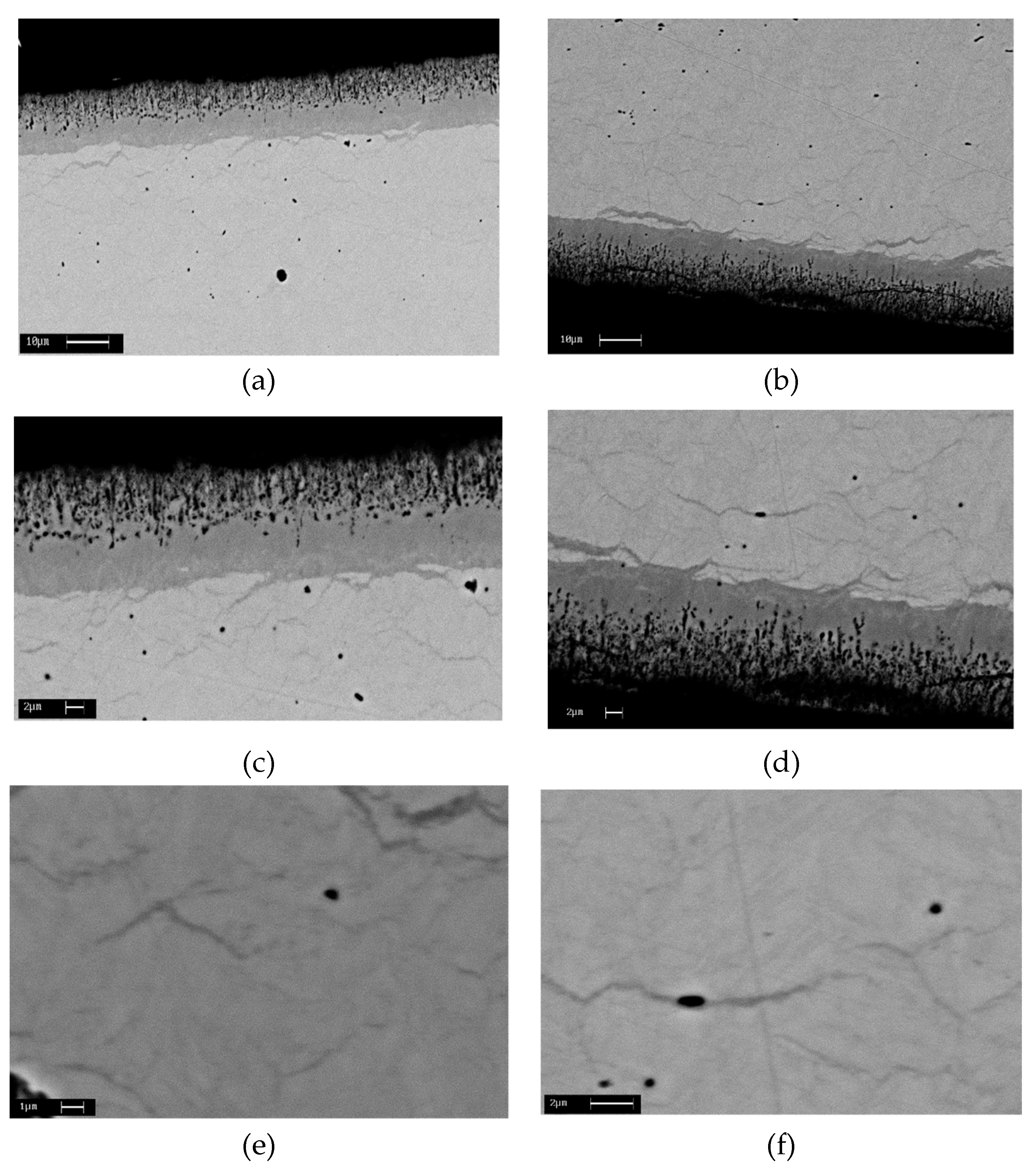
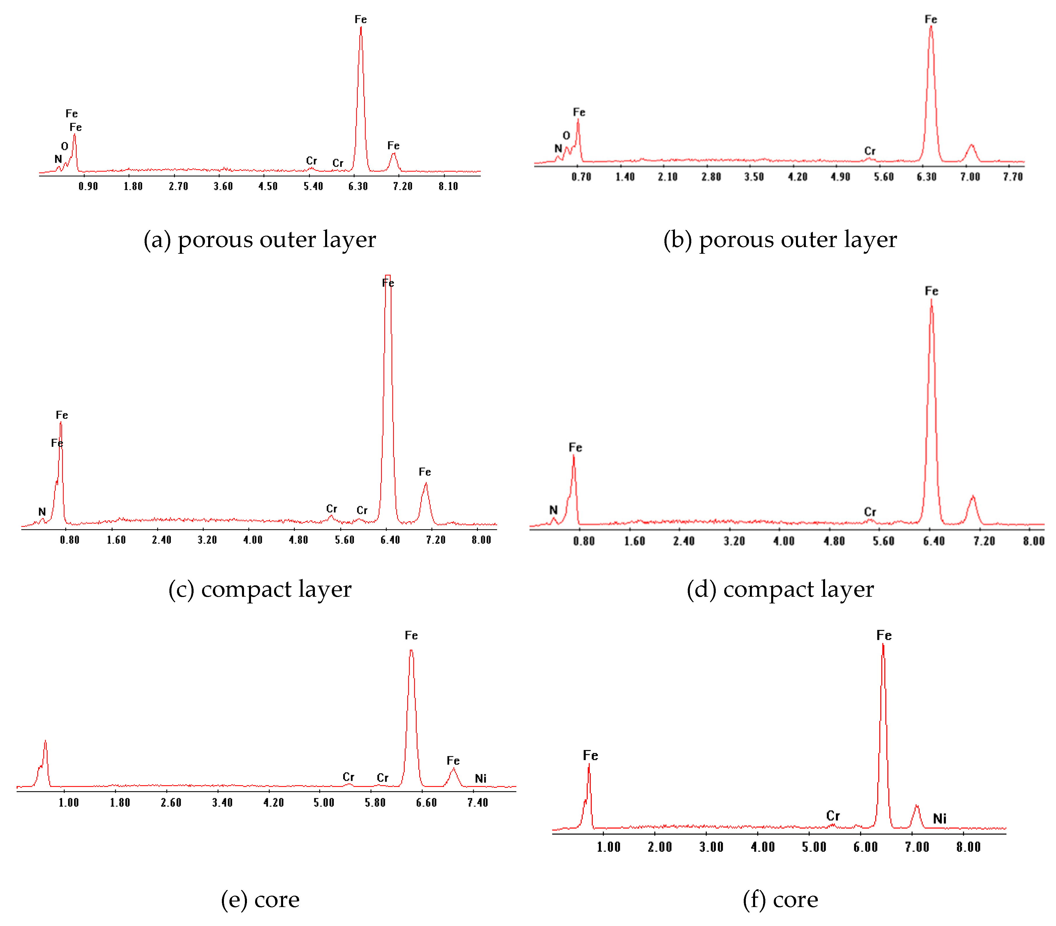
3.1. Microstructure
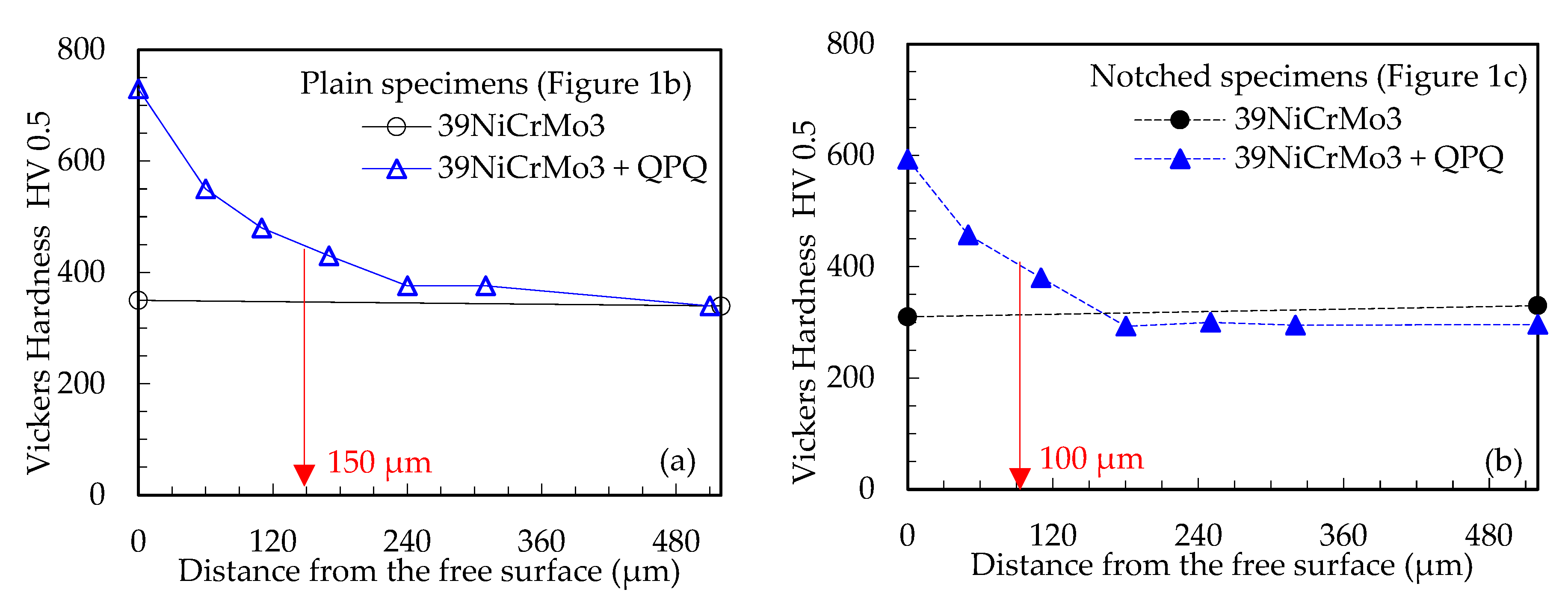
3.2. Microhardness
3.3. Surface Residual Stresses
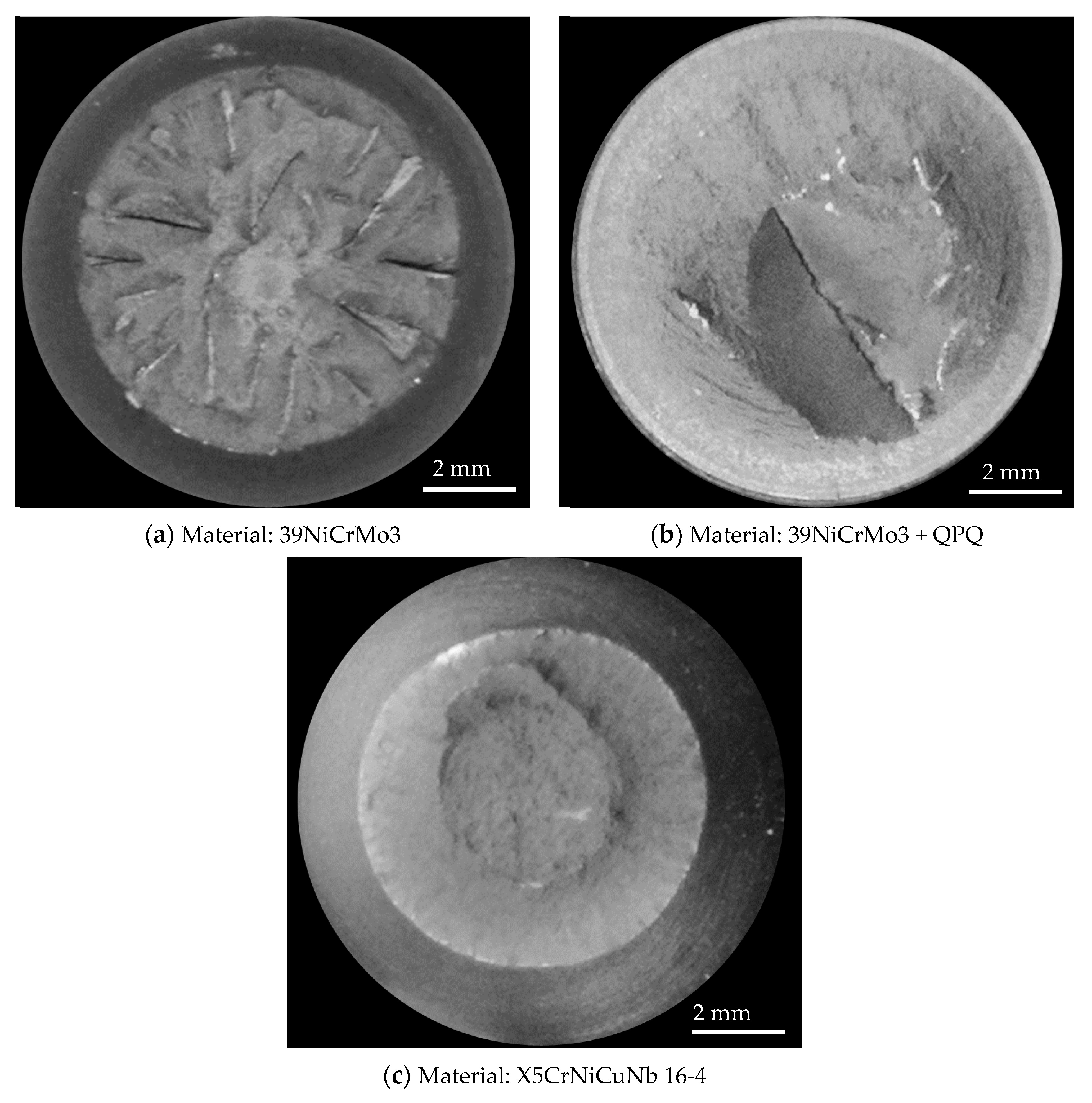
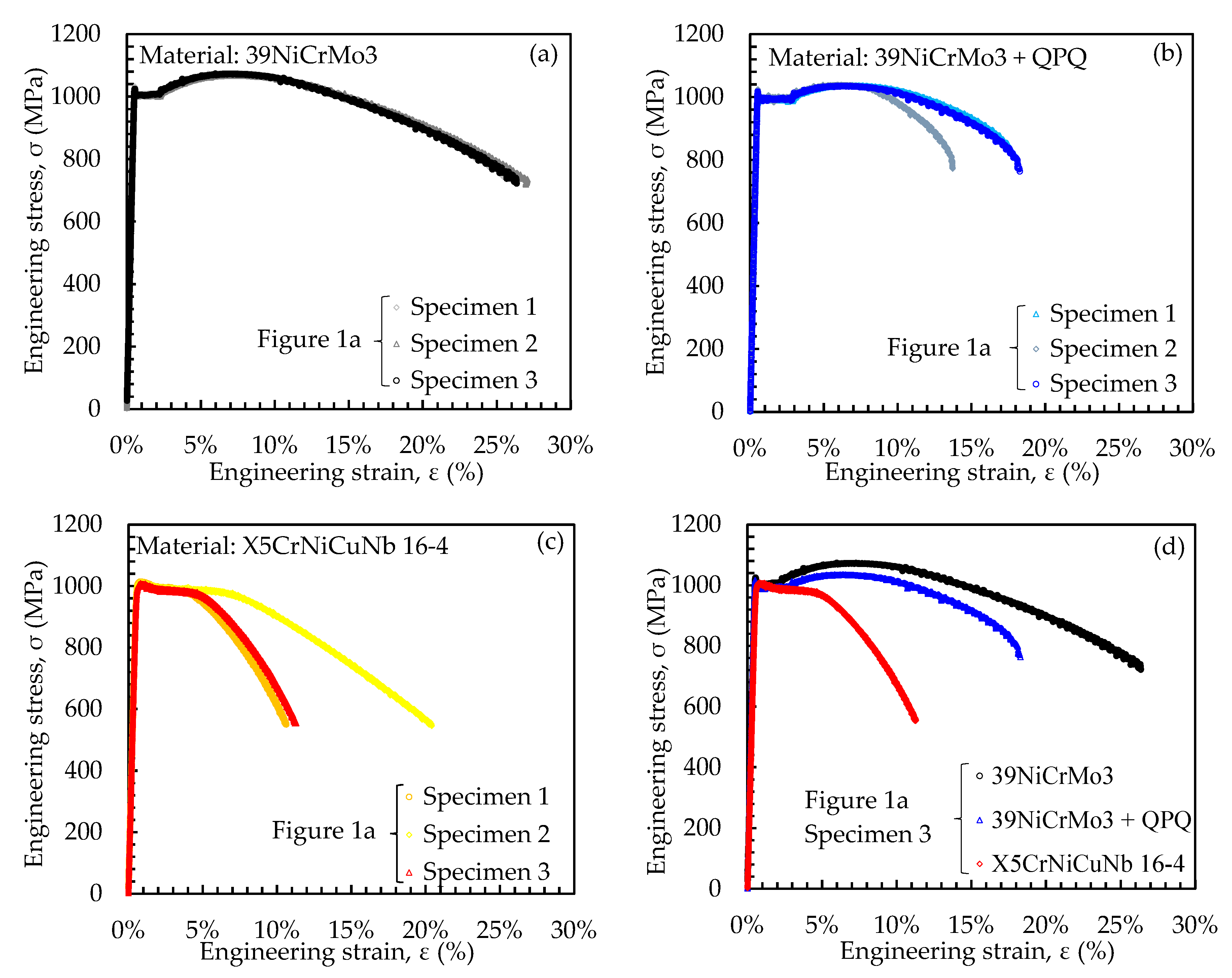
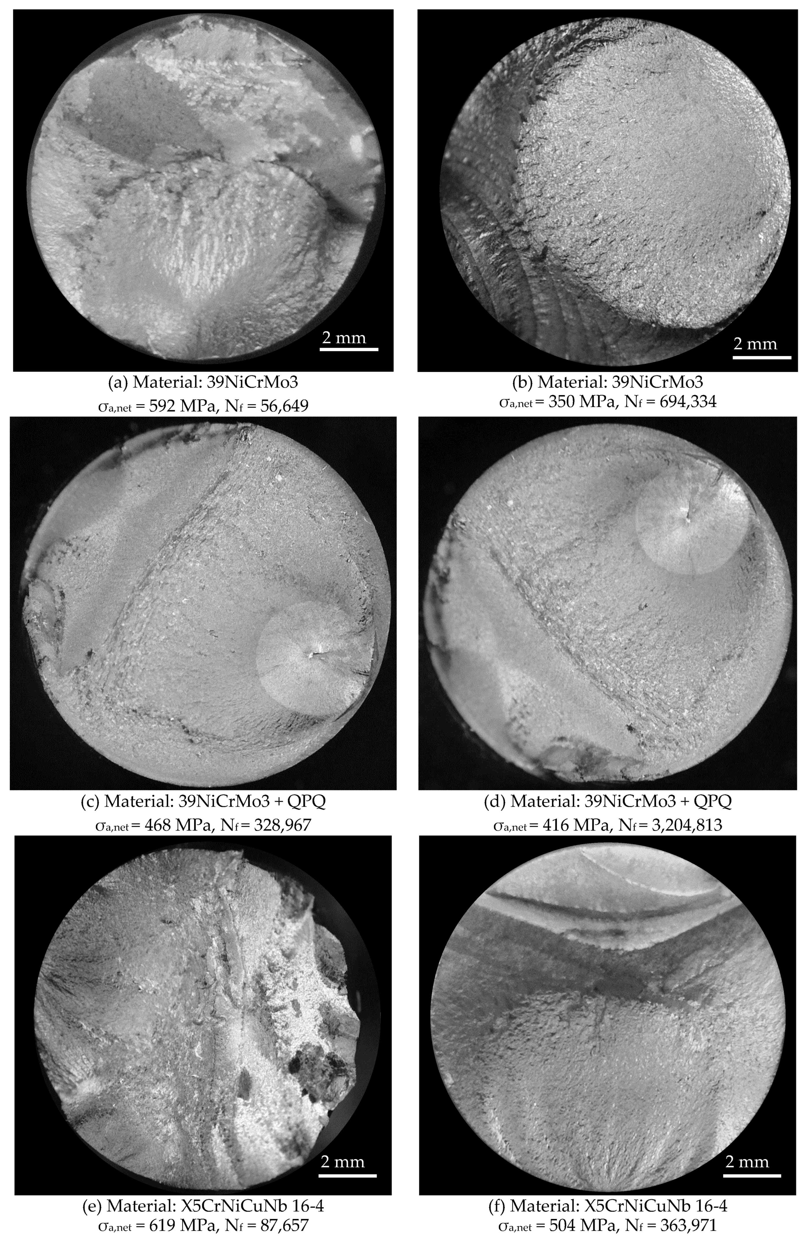
3.4. Static Tests: Analysis of Fracture Surfaces and Stress-Strain Curves
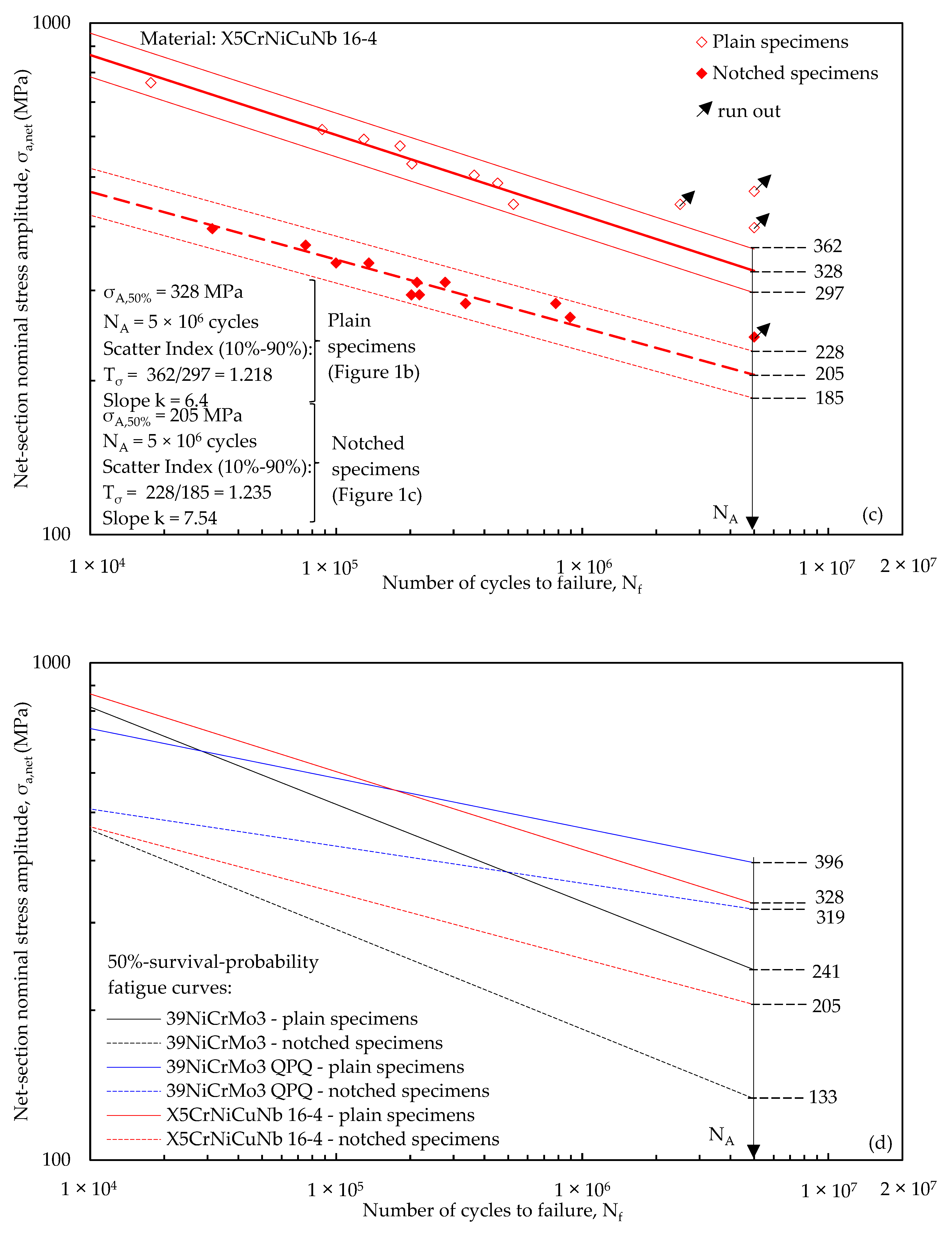
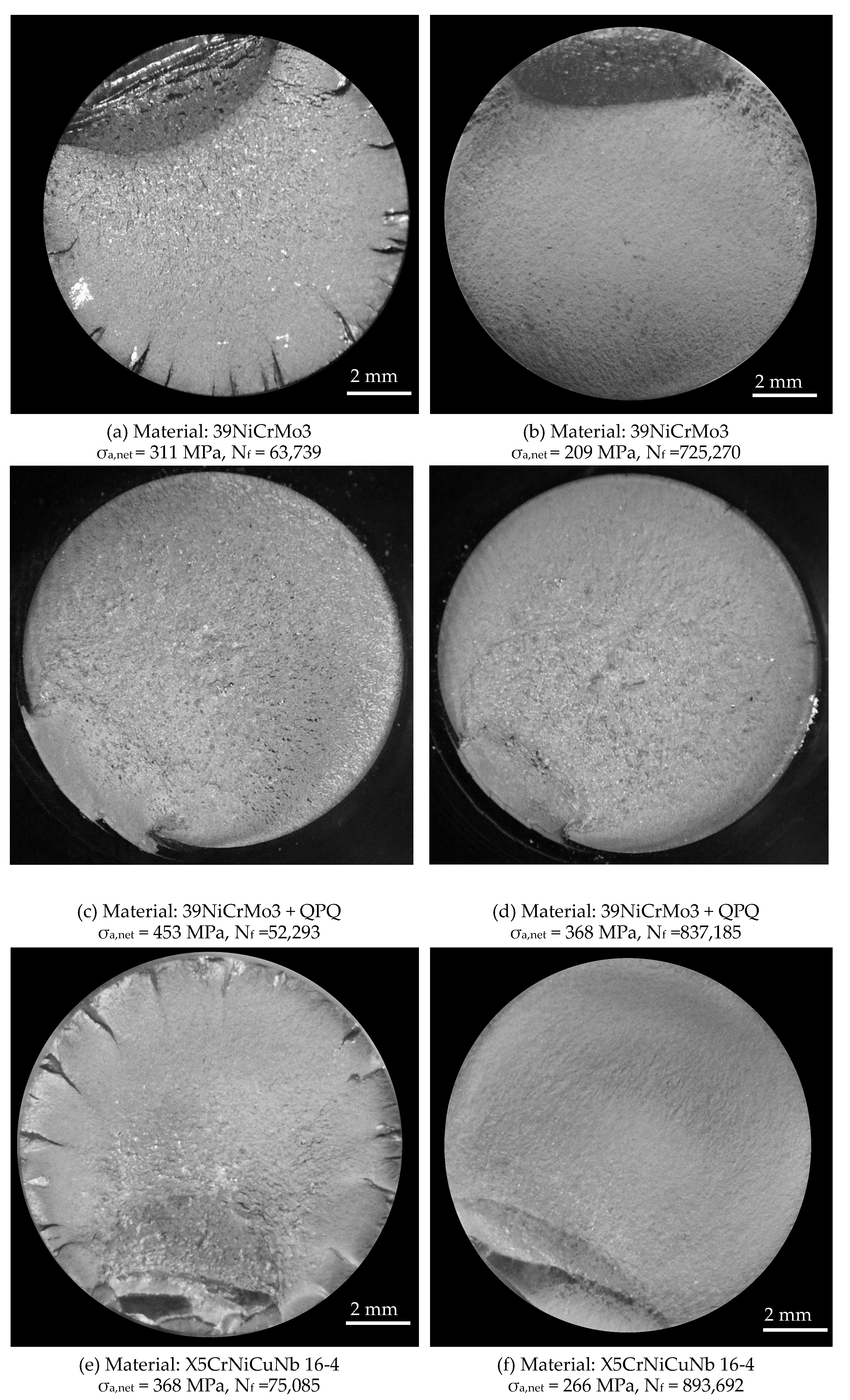
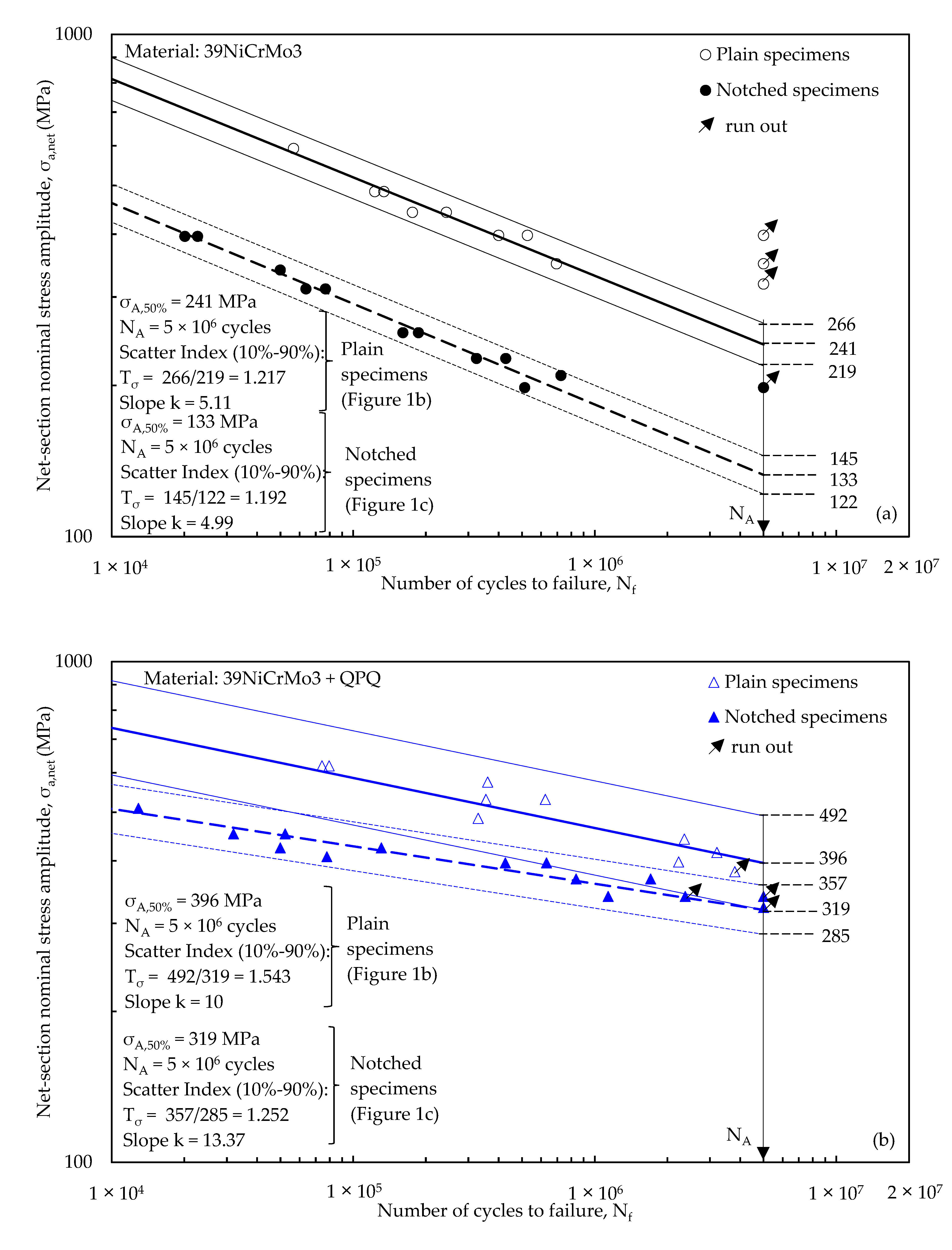
3.5. Fatigue Tests: Analysis of Fracture Surfaces and Woehler Curves
4. Conclusions
Author Contributions
Funding
Conflicts of Interest
References
- Almeida, E. Surface Treatments and Coatings for Metals. A General Overview. 1. Surface Treatments, Surface Preparation, and the Nature of Coatings. Ind. Eng. Chem. Res. 2001, 40, 3–14. [Google Scholar] [CrossRef]
- Sørensen, P.A.; Kiil, S.; Dam-Johansen, K.; Weinell, C.E. Anticorrosive coatings: A review. J. Coat. Technol. Res. 2009, 6, 135–176. [Google Scholar] [CrossRef]
- Schulze, V. Modern Mechanical Surface Treatment: States, Stability, Effects; Wiley-VCH: Hoboken, NJ, USA, 2006; ISBN 9783527313716. [Google Scholar]
- Vetter, J. Surface Treatments for Automotive Applications. In Coating Technology for Vehicle Applications; Springer International Publishing: Cham, Switzerland, 2015; pp. 91–132. [Google Scholar]
- Bell, T. Ferritic nitrocarburising. Heat Treat. Met. 1975, 2, 39–49. [Google Scholar]
- Bell, T. Gaseous and plasma nitrocarburizing. In ASM Handbook; ASM International: Materials Park, OH, USA, 1991; Volume 4, pp. 425–436. [Google Scholar]
- Mehrkam, Q.; Easterday, J.; Payne, B.; Foreman, R.; Vukovich, D.; Godding, A. Liquid nitriding of steels. In ASM Handbook; ASM International: Materials Park, OH, USA, 1991; Volume 4, pp. 410–419. [Google Scholar]
- Krishnaraj, N.; Iyer, K.J.L.; Sundaresan, S. Scuffing resistance of salt bath nitrocarburized medium carbon steel. Wear 1997, 210, 237–244. [Google Scholar] [CrossRef]
- Alsaran, A.; Karakan, M.; Celik, A.; Bulbul, F.; Efeoglu, I. Study on compound layer formed during plasma nitrocarburizing of AISI 5140 steel. J. Mater. Sci. Lett. 2003, 22, 1759–1761. [Google Scholar] [CrossRef]
- Limodin, N.; Verreman, Y. Fatigue strength improvement of a 4140 steel by gas nitriding: Influence of notch severity. Mater. Sci. Eng. 2006, 435–436, 460–467. [Google Scholar] [CrossRef]
- Funatani, K. Low-Temperature Salt Bath Nitriding of Steels. Met. Sci. Heat Treat. 2004, 46, 277–281. [Google Scholar] [CrossRef]
- Kunst, H. Improving Corrosion and Wear Resistance by Salt Bath Nitrocarburizing Plus Oxidizing in Automated Facilities; Pergamon Press: Oxford, UK, 1987. [Google Scholar]
- Wahl, G. Component properties after salt bath nitrocarburizing by Tufftride process. Heat Treat. Met. 1995, 3, 65–73. [Google Scholar]
- Li, H.; Luo, D.; Yeung, C.; Lau, K. Microstructural studies of QPQ complex salt bath heat-treated steels. J. Mater. Process. Technol. 1997, 69, 45–49. [Google Scholar] [CrossRef]
- Qiang, Y.H.; Ge, S.R.; Xue, Q.J. Microstructure and tribological behaviour of nitrocarburizing-quenching duplex treated steel. Tribol. Int. 1999, 32, 131–136. [Google Scholar] [CrossRef]
- Yeung, C.F.; Lau, K.H.; Li, H.Y.; Luo, D.F. Advanced QPC complex salt bath heat treatment. J. Mater. Process. Technol. 1997, 66, 249–252. [Google Scholar] [CrossRef]
- Marušić, K.; Otmačić, H.; Landek, D.; Cajner, F.; Stupnišek-Lisac, E. Modification of carbon steel surface by the Tenifer® process of nitrocarburizing and post-oxidation. Surf. Coat. Technol. 2006, 201, 3415–3421. [Google Scholar] [CrossRef]
- Li, G.; Wang, J.; Peng, Q.; Li, C.; Wang, Y.; Shen, B. Influence of salt bath nitrocarburizing and post-oxidation process on surface microstructure evolution of 17-4PH stainless steel. J. Mater. Process. Technol. 2008, 207, 187–192. [Google Scholar] [CrossRef]
- Shiozawa, K.; Lu, L.; Ishihara, S. S-N curve characteristics and subsurface crack initiation behaviour in ultra-long life fatigue of a high carbon-chromium bearing steel. Fatigue Fract. Eng. Mater. Struct. 2001, 24, 781–790. [Google Scholar] [CrossRef]
- Chandran, K.R.; Chang, P.; Cashman, G.T. Competing failure modes and complex S–N curves in fatigue of structural materials. Int. J. Fatigue 2010, 32, 482–491. [Google Scholar] [CrossRef]
- Cashman, G.T. A review of Competing Modes fatigue behavior. Int. J. Fatigue 2010, 32, 492–496. [Google Scholar] [CrossRef]
- Sakai, T.; Sato, Y.; Oguma, N. Characteristic S-N properties of high-carbon-chromium-bearing steel under axial loading in long-life fatigue. Fatigue Fract. Eng. Mater. Struct. 2002, 25, 765–773. [Google Scholar] [CrossRef]
- Bathias, C. There is no infinite fatigue life in metallic materials. Fatigue Fract. Eng. Mater. Struct. 1999, 22, 559–565. [Google Scholar] [CrossRef]
- Limodin, N.; Verreman, Y.; Tarfa, T.N. Axial fatigue of a gas-nitrided quenched and tempered AISI 4140 steel: Effect of nitriding depth. Fatigue Fract. Eng. Mater. Struct. 2003, 26, 811–820. [Google Scholar] [CrossRef]
- Wang, Q.Y.; Berard, J.Y.; Dubarre, A.; Baudry, G.; Rathery, S.; Bathias, C. Gigacycle fatigue of ferrous alloys. Fatigue Fract. Eng. Mater. Struct. 1999, 22, 667–672. [Google Scholar] [CrossRef]
- Preston, S. Bending fatigue strength of nitrocarburized steel SS2244. Mater. Sci. Eng. 1993, 160, 7–15. [Google Scholar] [CrossRef]
- Genel, K.; Demirkol, M.; Çapa, M. Effect of ion nitriding on fatigue behaviour of AISI 4140 steel. Mater. Sci. Eng. 2000, 279, 207–216. [Google Scholar] [CrossRef]
- Suh, C.-M.; Hwang, J.-K.; Son, K.-S.; Jang, H.-K. Fatigue characteristics of nitrided SACM 645 according to the nitriding condition and notch. Mater. Sci. Eng. 2005, 392, 31–37. [Google Scholar] [CrossRef]
- Tokaji, K.; Takahashi, S. Fatigue Strength and Subsurface Crack Initiation in Nitrided Low Alloy Steel SCM 435. Trans. Jpn. Soc. Mech. Eng. 2001, 67, 86–93. [Google Scholar] [CrossRef] [Green Version]
- Hussain, K.; Tauqir, A.; ul Haq, A.; Khan, A. Influence of gas nitriding on fatigue resistance of maraging steel. Int. J. Fatigue 1999, 21, 163–168. [Google Scholar] [CrossRef]
- Spies, H.J.; Trubitz, P. Fatigue of nitrided steels. In Fatigue 96; Elsevier: Berlin, Germany, 1996; pp. 1409–1414. [Google Scholar]
- Li, G.; Peng, Q.; Wang, J.; Li, C.; Wang, Y.; Gao, J.; Chen, S.; Shen, B. Surface microstructure of 316L austenitic stainless steel by the salt bath nitrocarburizing and post-oxidation process known as QPQ. Surf. Coat. Technol. 2008, 202, 2865–2870. [Google Scholar] [CrossRef]
- Yamada, Y.; Eto, H.; Konya, J.; Takahashi, K. Influence of crack-like surface defects on the fatigue limit of nitrocarburized carbon steel. IOP Conf. Ser. Mater. Sci. Eng. 2018, 372, 012005. [Google Scholar] [CrossRef]
- Zhang, J.W.; Lu, L.T.; Shiozawa, K.; Zhou, W.N.; Zhang, W.H. Effects of nitrocarburizing on fatigue property of medium carbon steel in very high cycle regime. Mater. Sci. Eng. 2011, 528, 7060–7067. [Google Scholar] [CrossRef]
- Zhang, J.W.; Lu, L.T.; Shiozawa, K.; Cui, G.D.; Zhang, W.H. Fatigue properties of oxynitrocarburized medium carbon railway axle steel in very high cycle regime. Int. J. Fatigue 2010, 32, 1805–1811. [Google Scholar] [CrossRef]
- Zhao, H.; Torres, A.; Prisbell, A.; Werner, A.; Abdelaal, A. Quench Polish Quench (QPQ) Coating Behavior Under Dynamic Loads. In Proceedings of the ASME 2017 International Mechanical Engineering Congress and Exposition, Tampa, FL, USA, 3–9 November 2017; American Society of Mechanical Engineers: New York, NY, USA, 2017. [Google Scholar]
- Zhang, J.W.; Lu, L.T.; Shiozawa, K.; Zhou, W.N.; Zhang, W.H. Effect of nitrocarburizing and post-oxidation on fatigue behavior of 35CrMo alloy steel in very high cycle fatigue regime. Int. J. Fatigue 2011, 33, 880–886. [Google Scholar] [CrossRef]
- Pérez, M.; Belzunce, F.J. A comparative study of salt-bath nitrocarburizing and gas nitriding followed by post-oxidation used as surface treatments of H13 hot forging dies. Surf. Coat. Technol. 2016, 305, 146–157. [Google Scholar] [CrossRef]
- Nobuki, T.; Hatate, M.; Kawasaki, Y.; Ikuta, A.; Hamasaka, N. Effects of Nitriding and Nitro-carburizing on the Fatigue Properties of Ductile Cast Iron. Int. J. Met. 2017, 11, 52–60. [Google Scholar] [CrossRef]
- Murakami, Y. Metal Fatigue: Effects of Small Defects and Nonmetallic Inclusions; Elsevier Science Ltd.: Amsterdam, The Netherlands, 2002; ISBN 9780128138762. [Google Scholar]
- Throop, J.; Reemsnyder, H. (Eds.) Residual Stress Effects in Fatigue; ASTM International: West Conshohocken, PA, USA, 1982; ISBN 978-0-8031-0711-3. [Google Scholar]
- Stephens, R.I.; Fatemi, A.; Stephens, R.R.; Fuchs, H.O. Metal Fatigue in Engineering; Wiley: Hoboken, NJ, USA, 2001; ISBN 9780471510598. [Google Scholar]


| Material | C | Si | Mn | P | S | Cr | Mo | Ni | Cu | Nb | Ti | Al | Sn | Co |
|---|---|---|---|---|---|---|---|---|---|---|---|---|---|---|
| 39NiCrMo3 | 0.4 | 0.27 | 0.71 | 0.016 | 0.02 | 0.83 | 0.19 | 0.78 | 0.23 | 0.002 | 0.13 | 0.02 | 0.012 | - |
| X5CrNiCuNb 16-4 | 0.14 | 0.27 | 0.86 | 0.022 | 0.027 | 15.57 | 0.12 | 4.52 | 3.26 | 0.24 | - | - | - | 0.020 |
| Material | Specimen Geometry * | Layer | Fe (%) | Cr (%) | Ni (%) | N (%) | O (%) | S (%) |
|---|---|---|---|---|---|---|---|---|
| 39NiCrMo3 + QPQ | Plain | Porous outer layer | 69.02 | 0.87 | - | 18.40 | 11.71 | - |
| Compact layer | 84.24 | 1.11 | - | 14.65 | - | - | ||
| Core | 98.38 | 1.11 | 0.51 | - | - | - | ||
| Notched | Porous outer layer | 61.27 | 0.81 | - | 18.65 | 19.27 | - | |
| Compact layer | 79.39 | 0.78 | - | 19.83 | - | - | ||
| Core | 98.10 | 1.17 | 0.74 | - | - | - |
| Material | Specimen Geometry * | σxx (MPa) | σzz (MPa) |
|---|---|---|---|
| 39NiCrMo3 | plain notched | −267 −48 | −130 −27 |
| 39NiCrMo3 + QPQ | plain notched | −418 −412 | −408 −364 |
| Material | Specimen Geometry * | dnet (mm) | dgross (mm) | E (MPa) | σR (MPa) | σp,02 (MPa) | A (%) |
|---|---|---|---|---|---|---|---|
| 39NiCrMo3 | plain | 10 | 20 | 206,185 | 1168 | 1013 | 14.3 |
| 39NiCrMo3 + QPQ | plain | 10 | 20 | 208,433 | 1117 | 1005 | 11.4 |
| X5CrNiCuNb 16-4 | plain | 10 | 20 | 191,871 | 1030 | 1020 | 12.4 |
| Material | Specimen Geometry * | ρ (mm) | dnet (mm) | dgross (mm) | Ra^ (μm) | Kt,net | N° Data | N° Runout | σA+ (MPa) | k° |
|---|---|---|---|---|---|---|---|---|---|---|
| 39NiCrMo3 | plain notched | - 1.5 | 12 | 20 | 0.83 | 1.05 2.34 | 12 12 | 3 1 | 241 133 | 5.11 4.99 |
| 39NiCrMo3 + QPQ | plain notched | - 1.5 | 12 | 20 | 0.84 | 1.05 2.34 | 11 14 | 1 3 | 396 319 | 10.0 13.37 |
| X5CrNiCuNb 16-4 | plain notched | - 1.5 | 12 | 20 | 0.76 | 1.05 2.34 | 11 12 | 3 1 | 328 205 | 6.40 7.54 |
© 2019 by the authors. Licensee MDPI, Basel, Switzerland. This article is an open access article distributed under the terms and conditions of the Creative Commons Attribution (CC BY) license (http://creativecommons.org/licenses/by/4.0/).
Share and Cite
Campagnolo, A.; Dabalà, M.; Meneghetti, G. Effect of Salt Bath Nitrocarburizing and Post-Oxidation on Static and Fatigue Behaviours of a Construction Steel. Metals 2019, 9, 1306. https://doi.org/10.3390/met9121306
Campagnolo A, Dabalà M, Meneghetti G. Effect of Salt Bath Nitrocarburizing and Post-Oxidation on Static and Fatigue Behaviours of a Construction Steel. Metals. 2019; 9(12):1306. https://doi.org/10.3390/met9121306
Chicago/Turabian StyleCampagnolo, Alberto, Manuele Dabalà, and Giovanni Meneghetti. 2019. "Effect of Salt Bath Nitrocarburizing and Post-Oxidation on Static and Fatigue Behaviours of a Construction Steel" Metals 9, no. 12: 1306. https://doi.org/10.3390/met9121306
APA StyleCampagnolo, A., Dabalà, M., & Meneghetti, G. (2019). Effect of Salt Bath Nitrocarburizing and Post-Oxidation on Static and Fatigue Behaviours of a Construction Steel. Metals, 9(12), 1306. https://doi.org/10.3390/met9121306