1. Introduction
It is a significant challenge that replacement of over critical size bone defects result from trauma and bone diseases in the field of orthopedic and craniofacial surgery [
1,
2]. To treat bone disease and reconstruct lost bone tissues, bone tissue engineering (BTE) is considered to be a valid approach to remediate problems of disease transmission and limited availability in bone grafting [
3,
4]. Titanium and its alloys have been widely applied as orthopedic implant materials for their excellent mechanical properties, biocompatibility and corrosion resistance [
5]. However, the mismatch of mechanical properties between metals and natural bone lead to stress shielding and, furthermore, result in bone resorption and implant failure [
6]. Porous scaffolds are introduced as bone substitute in view of its controllable mechanical properties to avoid the stress shielding effect and to improve implant material longevity [
7,
8,
9]. Taking a biomechanical and clinical point of view, mechanical loading is expected during bone regeneration. The porous scaffolds should offer adequate mechanical strength to ensure fixation stability. Otherwise, the Young’s modulus of these scaffolds should approximate that of the host bone tissues, avoiding potential stress shielding [
10]. Therefore, it is essential and critical to consider the mechanical properties of scaffolds.
It has been confirmed that the mechanical properties are influenced greatly by the pore architecture of scaffolds [
11]. It is necessary to regulate the pore structure of porous scaffolds to obtain appropriate mechanical properties [
12]. Many studies suggest that the elastic modulus of porous materials decrease as their porosity increases, in general [
13,
14]. Alternatively, the mechanical properties of scaffolds may be adjusted by altering the pore structure. The test results of two separate scaffolds with different pore structures show a variation in modulus, specifically, the scaffolds with a spherical pore exhibits a higher elastic modulus than the one with a cylindrical pore [
15]. The mechanical properties also are influenced by pore size. Considering Park’s report, the elastic modulus of polycaprolactone (PCL) scaffolds reduce from 10.3 MPa to about 3 MPa, while pore sizes rise from 125 μm to 300 μm [
16]. Santos and his cooperators established a function of strut length and diameter to describe the equivalent elastic modulus [
17,
18]. Considering the influencing factors fully, a first-order equation is established to predict Young’s modulus, which is related to unit size, structure size, and structure shape [
14].
Additive manufacturing (AM) is considered an optimal method to fabricate open-porous metallic scaffolds for its wide range of design freedom [
19,
20]. Furthermore, AM productions have a high accuracy and scaffolds with specific porosity, pore size and pore structure could be obtained as expected [
14]. Additionally, the scaffolds fabricated with additive manufacturing technology are critically characterized by the processes. The mechanical properties are greatly influenced by the process parameters [
21,
22,
23] and post-treatment [
24,
25], and there are many reports on the mechanical properties of AM Ti6Al4V published up to now [
20,
26]. A lower maximum strength, but higher ductility product would result from hot isostatic pressing (HIP) treated Ti6Al4V [
27]. Unfortunately, only a few studies focused on the mechanical properties of porous structures affecting heat treatments so far [
28]. The conspicuous brittleness was found in HIP-treated high porosity Ti6Al4V scaffolds during preliminary experimentation. The aim of this study is to investigate the mechanism of unexpected brittle transition results from heat treatment. The mechanical properties, as well as the microstructure of the heat-treated specimens, is studied.
2. Materials and Methods
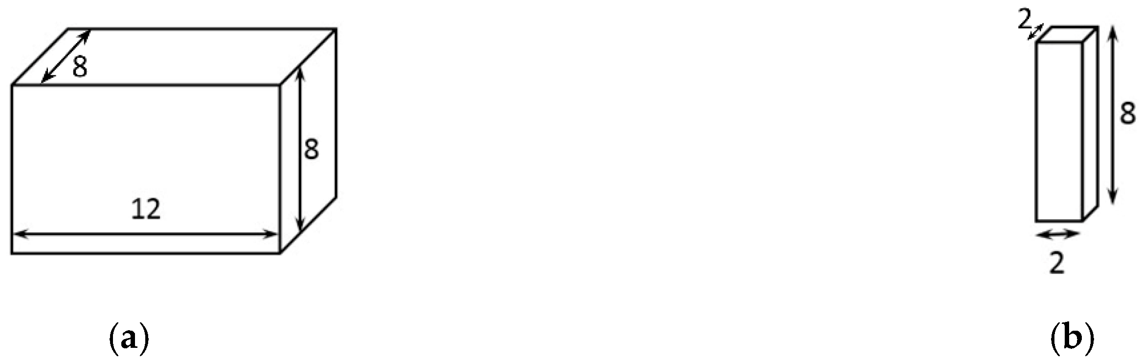
Ti6Al4V was chosen as research the object in this article due to its wide application for orthopedic implants. All specimens were fabricated with Laser-Powder bed fusion (L-PBF) technology for its excellent ability to fabricate complicated structures. Samples were treated by HIP (hot isostatic pressing) to eliminate residual stress and pores through materials, and the role of heat treatment in the change of materials was identified by comparing with as-built samples. Specimens with or without interspace were designed to characterise the influence of a porous structure on the properties of L-PBF Ti6Al4V. Porous specimens with various dimensions were designed to change their specific surface area, furthermore, to research the roles of the oxide layer formed after HIP.
Samples 1,2 were solid parts with specific surface areas of 0.67 mm
2/mm
3 and 2.17 mm
2/mm
3, separately, as shown in
Figure 1a,b. Specific surface area was defined as the ratio of total material surface areas (
s) to sample volume (
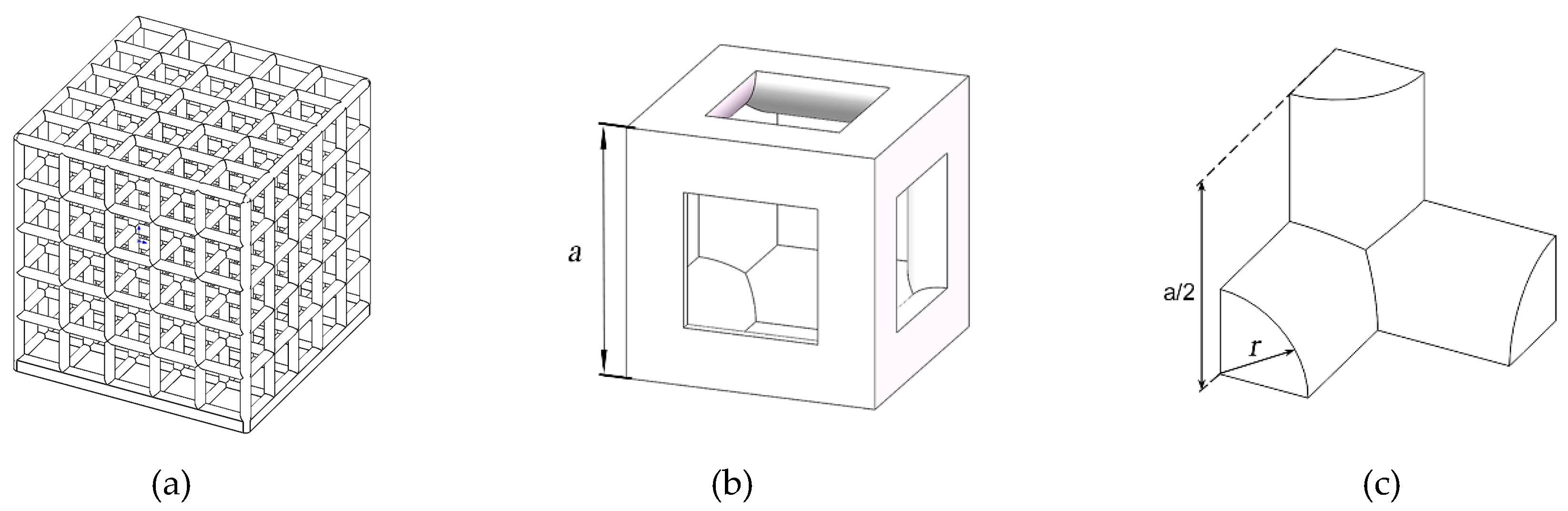
V). The simple cubic cell was chosen as the unit cell structure of porous scaffolds in this study.
Figure 2a shows the porous scaffolds obtained by the arrangement of a number of cell units. A cubic cell was composed of 12 quarter-cylindrical struts with a length of
a and a radius of
r, as shown in
Figure 2b,c. Apparent porosity (
ρa) was defined as the ratio of interspace volume to sample volume. The parameters of porous scaffolds with various dimensions of struts are listed in
Table 1. Regarding all unit cells, the edge length was a constant
a of 2 mm, while the apparent porosity (
ρa) and specific surface area (
s/V) increased with a decreasing radius (
r).
EOS M280 (M280, EOS, Maisach, Germany) equipped with a YAG fiber laser was chosen to produce these samples with a scanning speed v of 1250 mm/s, a laser power P of 170 W, a hatch spacing D of 100 μm and a layer thickness t of 30 μm. The main parameters of the laser are as follows: a wavelength of 1070 nm, a maximum power of 200 W and a spot size of 100 μm. Ti6Al4V powder with an average particle diameter of 50 μm was used to fit for practical application. As-built samples were cut off by wire electric discharge machining, and a post treatment of a hot-isostatic pressure (HIP400, EPSI, Temse, Belgium) process was carried out at 130 MPa, 950 °C for 3 h in an argon atmosphere.
The surface morphology and microstructure of the as-built and HIP-treated Ti6Al4V were observed to characterize the roles of post-treatment. Optical microscope (OM) (RAYJX33, Dinglu, Dongguan, China) was used to observe the microstructure of Ti6Al4V after a series of pretreatment: grinding with SiC grinding paper up to a fine of 7000 grit size, polishing with diamond brightener up to a fine of 0.5 μm diameter, and etching with an etchant of 8 vol.% HF, 15 vol.% HNO3 in 77 vol.% deionized water solution. Transmission Electron Microscopy (TEM) (JEM-2100, JEOL, Tokyo, Japan) was used to reveal the phase transition and crystal structure of the as-built and HIP-treated Ti6Al4V, operated at 200 kV. A scanning electron microscope (SEM) (SU8220, HITACHI, Tokyo, Japan) was used to analyze the surface details and fracture surfaces of porous scaffolds before and after heat treatment.
The mechanical properties of the as-built and HIP-treated Ti6Al4V were tested to evaluate the roles of the HIP treatment. The density of Ti6Al4V was measured using the standard Archimedes method with electronic balance (AE323J, SHUNYU, Shanghai, China), and the hardness was measured with a hardness tester (HVD-1000AP, JVJING, Shanghai, China) under a test load of 19.6 N. A compression test was carried out on a universal mechanical testing machine (E45, MTS, Eden Prairie, MN, USA) equipped with 100 kN load cell at a loading speed of 0.03 mm/s. Stress in specimens was defined as the specific value of pressure load and cross-sectional area. Strain was calculated by dividing the beam displacement with the length of samples. The compression stiffness (K), critical stress (σc) and compression strength (σb) were defined from compression stress-strain curves, the maximum slope of a compression curve was regarded as the K, the minimum stress initiating plastic deformation was regarded as the σc, and the maximum stress of the compression curve was regarded as the σb.
3. Results
AM (additive manufacturing) products may contain some defects reducing their applicability. Pores in materials formed by molten metal trapping surrounding gas result in a decrease of its strength. Residual stress formed by a high temperature gradient may lead to early cracking. HIP is an effective method to eliminate residual stress for its high temperature. Additionally, plastic deformation in materials occurs more easily at a high environmental temperature and circular-like pore defects can be compressed to tiny gaps at high pressure. Furthermore, the macro-morphology and microstructure of materials are changed obviously.
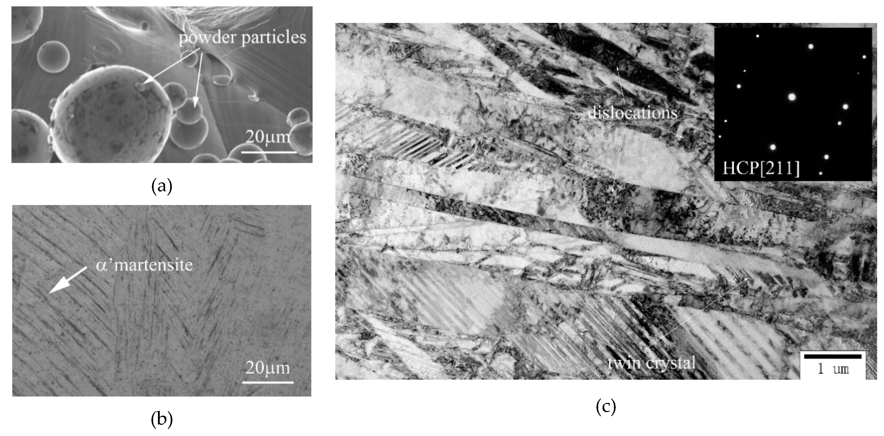
Smooth surfaces with some powder particles can be seen on the original scaffolds, as shown in
Figure 3a. Columnar crystals with very fine acicular α’ martensitic structures along the building direction is a typical microstructure of the as-built Ti6Al4V, which was observed with OM and shown in
Figure 3b. To confirm the conclusion, TEM was used to characterize the microstructure with bright field images (BFI) and identify the phase component with electron diffraction patterns (EDP). EDP of the primary materials confirms that the main phase component of the as-built samples is α’ martensitic structure and BFI shows acicular α’ plates fully filled with numerous twin crystals and dislocations, as shown in
Figure 3c.
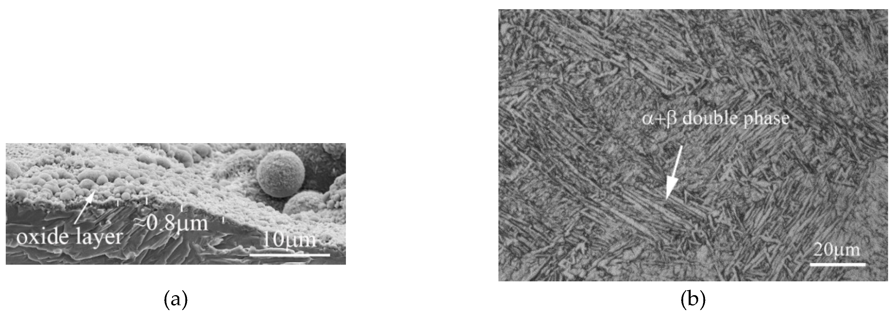
After HIP treatment, the surface topography of Ti6Al4V is changed obviously, the smooth surface with a silver-grey metallic luster turns into a surface adhered with rough black oxide. To characterize the surface oxide layer, SEM was used to observe the surface topography of the porous scaffolds and examine the thickness of the oxide layers. An average thickness of an 0.8 μm oxide layer formed a rough and uneven surface, seen in
Figure 4a. The microstructure of Ti6Al4V transforms into an α + β dual-phase structure with an average thickness of 2 μm of α phase lamellae after HIP treatment, at a higher environmental temperature (950 °C) than the phase transition temperature (882 °C), shown in
Figure 4b.
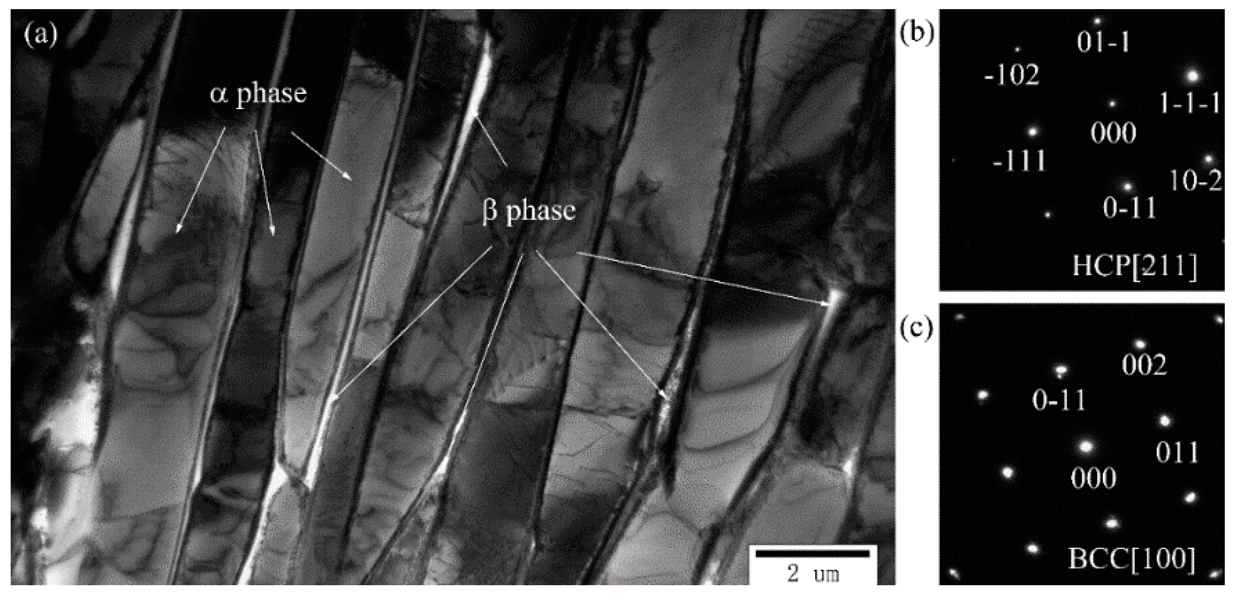
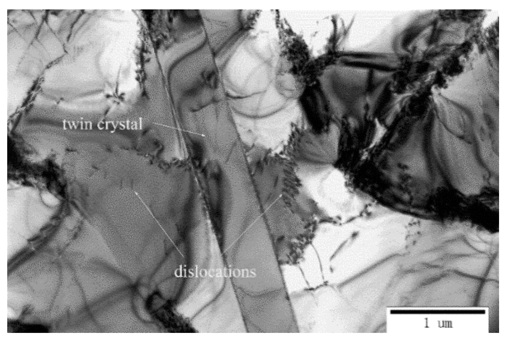
To further understand the phase transformation and the role of HIP treatment, the HIP-treated samples were characterized by TEM. The BFI presents the detail of the microstructure evolution and the EDP confirms the phase component. The EDPs of phases confirm that the original α’ phase were fully decomposed into an α phase with an HCP lattice structure and β phase with a BCC lattice structure. The BFI presents elongated α phase grains embedded in β phase grain boundaries, shown in
Figure 5. Moreover,
Figure 6 shows a decreasing density of dislocations and twin crystals in HIP-treated samples. Defects such as dislocations and twin crystals are contributing to the strengthening of materials. HIP treatment should result in a decline of the yield strength of L-PBF Ti6Al4V.
There still is some residual oxygen which will play an important role at an extended time or high temperature in a vacuum state. Guo et al. found a 60 nm oxide layer thickness formed on the surface of Ti55 powder in a vacuum state over 12 months [
29]. It is reasonable to infer an oxide layer will be formed earlier at a higher temperature. Prior to HIP processing, the container was filled with argon gas after being vacuum sealed. There must be some residual oxygen in argon gas if failing to create an absolute vacuum. Oxide layers formed on Ti6Al4V by chemical reactions between residual oxygen and alloy elements, such as Ti which is the main component, as shown in
Figure 4a. A sheet with a thickness of 0.5 mm was cut from the middle of the solid specimens (
Figure 1a) along the building direction and grinded with grinding papers to 100 μm. Then, a disc sample with a diameter of 3 mm and a thickness of 50 μm was obtained by punching from the sheet next to the up surface and thinning by ion milling. The oxygen content of the samples from the surface to the inside was measured along their diameter by transmission electron microscopy equipped with EDS, as shown in
Table 2, which revealed a high oxygen concentration of 34.92% at the adjoining surface HIPed Ti6Al4V. Comparing the chemical components of Ti6Al4V powder and the as-built Ti6Al4V, it was confirmed that the oxygen came from the surrounding atmosphere. Furthermore, the greatest gradient of oxygen concentration formed between the Ti6Al4V surface and the internal material, thus oxygen atoms migrated into materials according to Fick’s first law. Grain boundaries, phase boundaries, dislocations are fast diffusion channels benefitted by their high density vacancy defect, which is abundant in the as-built Ti6Al4V shown in
Figure 3c. Additionally, high temperature can accelerate atomic motion, which contributes to improve the atomic diffusion rate. Therefore, oxygen atoms diffused from the surface into materials along fast channels driven by a concentration gradient formed a diffusion layer with a gradient of oxygen concentration.
The density of L-PBF products may reflect the volume of pore defects and the quality of products. It was anticipated that the density of Ti6Al4V would rise after HIP treatment. The densities of the solid samples are listed in
Table 3. Data No. 1 and No. 2 are test results of the as-built and HIP-treated Ti6Al4V, with dimensions shown in
Figure 1a, respectively. Considering the influence of specific surface areas, HIP-treated samples, with dimensions shown in
Figure 1b, were tested and the results were listed in data No. 3. To eliminate the effect of the oxide layer, HIP-treated specimens were ground with SiC grinding paper and higher densities were obtained in data No. 4.
Comparing the results of the as-built and HIP-treated Ti6Al4V with the same dimensions, the post-treatment improved the density of the materials, as expected. The density of smaller specimens declined unexpectedly, which may be a result of the higher specific surface area leading to a higher volume ratio of oxide film. An increased density of ground samples confirmed this supposition. It means the oxide layer played a more important role, relative to higher specific surface area specimens. Thus, the influence of the oxide layer should be given more attention in porous structures composed with numerous tiny struts.
The phase transition of Ti6Al4V after HIP treatment must lead to an observable variation in mechanical behavior. Moreover, the hardness of materials may reflect their yield strength to a certain extent. The hardness of the as-built and HIP-treated Ti6Al4V are listed in
Table 4. A decline in mean hardness indicates a decrease in yield strength after HIP treatment.
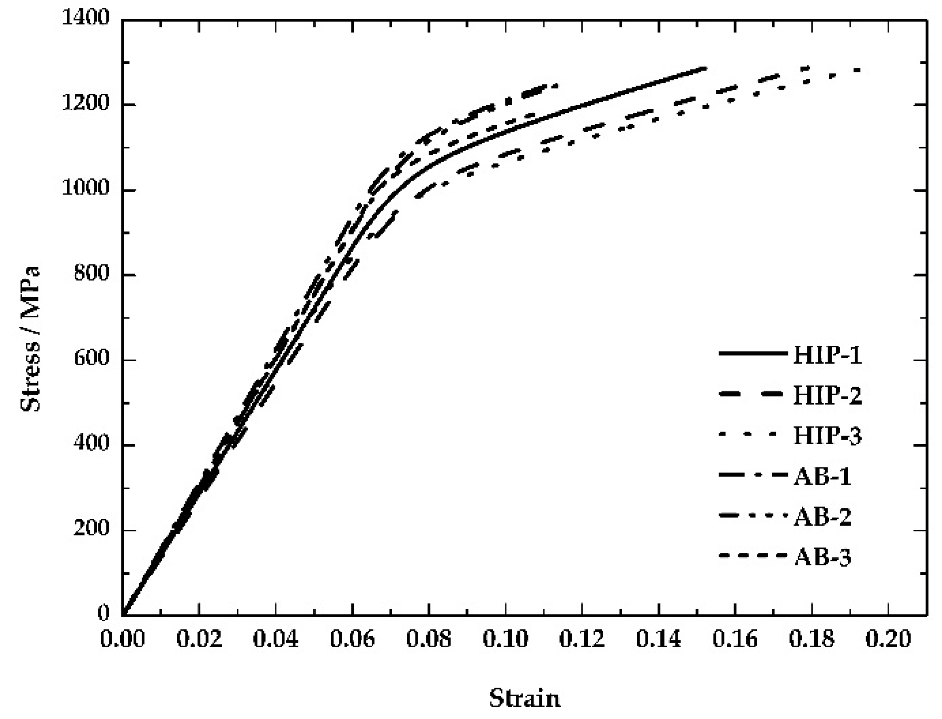
Mechanical properties can be characterized by stress-strain curves.
Figure 7 shows compression curves of the as-built and HIP-treated samples, with dimensions shown in
Figure 1a. The decreased compression stiffness and critical stress indicate that the property’s resistance to deformation reduced clearly after HIP treatment. As mentioned above, the microstructure of L-PBF Ti6Al4V transformed into α + β phases. First, plastic deformation of the β phase was much easier than in the original α’ phase. The decreased density of the twin grains and dislocation also reduced the resistance to plastic deformation. The compression stiffness (
K) and critical stress (
σc) are listed in
Table 5.
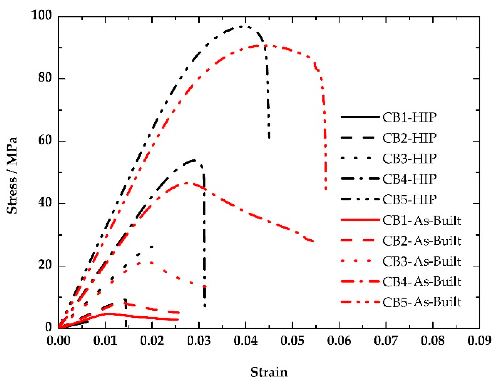
Porous scaffolds prepared with the same process should show the similar evolution law of solid samples.
Figure 8, however, shows that the compression stiffness, critical stress and compression strength of porous scaffolds with radii above 0.26 mm increased after HIP treatment; only porous scaffolds with radii of 0.2 mm decreased in mechanical parameters, as expected. A significant decrease in toughness also was presented in all HIP-treated porous scaffolds. The oxide layer formed on the surface of porous scaffolds increased the brittleness of materials, which led to fracture at lower strain. Conversely, the oxide layer and diffusion layer also improved the capability of resistance to deformation. Thus, the HIP-treated porous scaffolds presented higher compression stiffness, critical stress and compression strength and lower toughness.
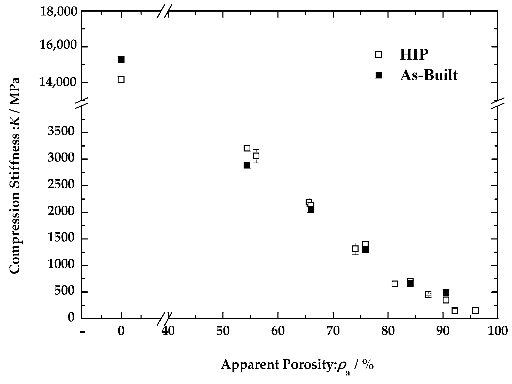
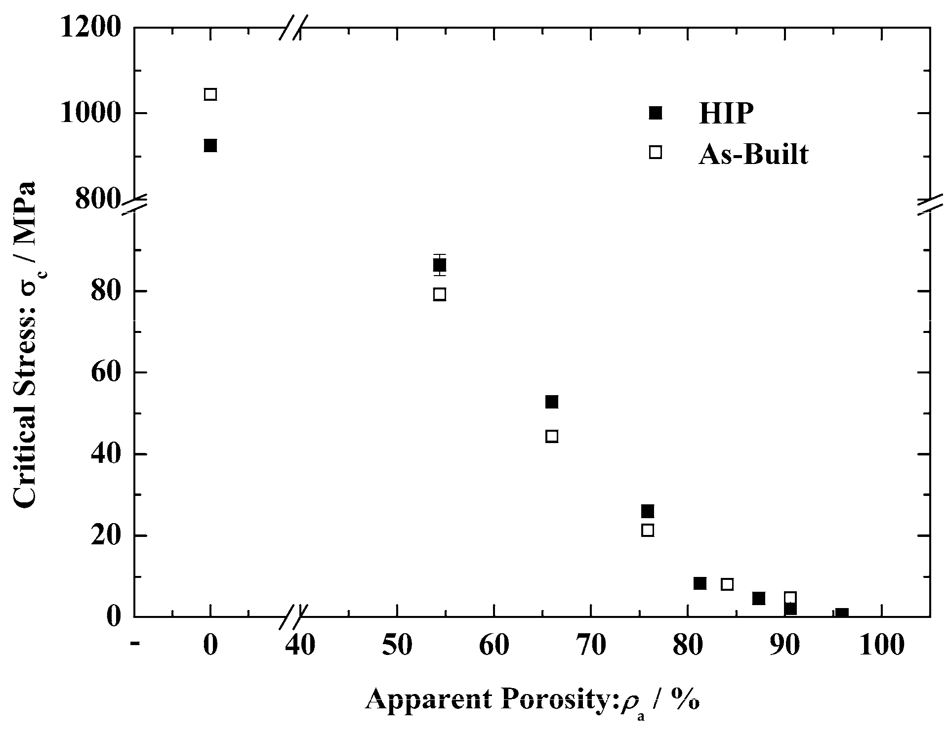
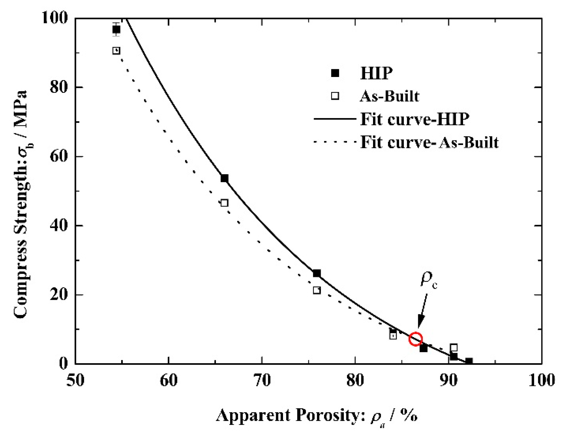
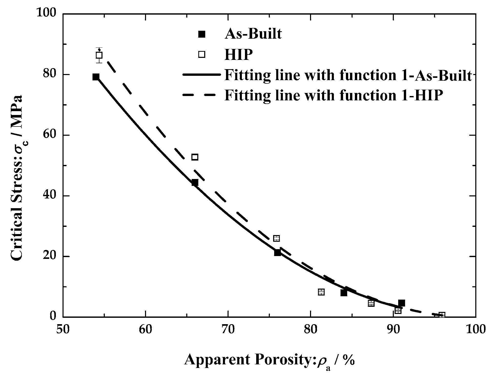
The compression stiffness, critical stress and compressive strengths varying with apparent porosity of scaffolds are shown in
Figure 9,
Figure 10 and
Figure 11. The relationship between the mechanical indexes and apparent porosity can be described by an exponential function with various coefficients. The three parameters decrease with increasing apparent porosity and there is critical apparent porosity (
ρc), as the relative position of the mechanical property parameters of the as built and HIP-treated changes when apparent porosity of the porous scaffolds cross the critical value. The mechanical properties of HIP-treated porous Ti6Al4V with lower apparent porosity were expected to be higher than that of the as-built ones but, on the contrary, the mechanical property parameters of porous Ti6Al4V with higher apparent porosity presented higher values, though the difference between as-built and HIP-treated samples was not significant.
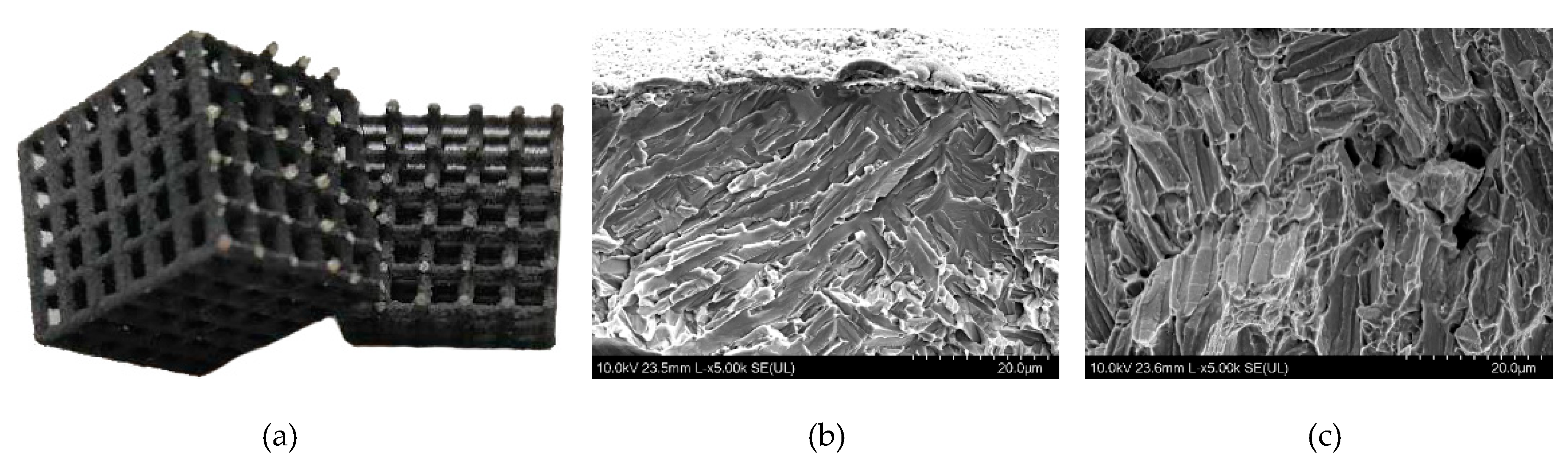
HIP-treated porous scaffolds are less elongated compared to the as-built ones shown in
Figure 8. Comparing the fracture morphology of the as-built and HIP porous scaffolds, two completely different fracture modes are shown in
Figure 12. The failure sample of the as-built scaffolds exhibited an unstable deformation for good toughness of Ti6Al4V [
30]. A brittle fracture mode presented in HIP porous scaffolds (
Figure 12a) indicated that the fracture mode of Ti6Al4V porous scaffolds transforms from ductile fracture into brittle fracture during post-treatment. Additionally,
Figure 12b shows the cleavage fracture in cylinder struts subsurface, and there are some dimples in the cylinder strut core located at grain boundaries, shown in
Figure 12c. The different fracture morphologies varying with position may result from oxygen atom diffusion as mentioned above.
4. Discussion
Regarding a high cooling rate and high temperature gradient during L-PBF process, the microstructure of the as-built Ti6Al4V is a fine α’ martensitic containing a high density of dislocations and twin crystals. Therefore, the yield strength of the as-built Ti6Al4V is higher than that of the commercial Ti6Al4V [
30]. Unfortunately, there are numerous pores formed in solid parts during the L-PBF process which may lead to stress concentration and, furthermore, a decrease in the fatigue strength and tensile strength of the materials. An appropriate pressure load may result in a reduction of pore volume by local plastic deformation at high temperatures. A pressure load of 130 MPa was taken during HIP treatment, and the density of L-PBF Ti6Al4V increased from 4.31 g/cm
3 to 4.38 g/cm
3, approaching a standard density of Ti6Al4V (4.4 g/cm
3). This result confirms that HIP is an effective method to eliminate pores in materials.
To facilitate deformation, a temperature of 950 °C was set during the HIP process, which is higher than the phase transition temperature (882 °C) of Ti6Al4V. After HIP treatment, the microstructure transforms from an α’ martensite to α + β phases Widmanstatten. Additionally, the densities of dislocation and twin crystal are reduced significantly. While reducing strengthening factors, plastic deformation becomes much easier, the mechanical properties of Ti6Al4V show a decrease in strength and an increase in toughness. The consistent conclusion is obtained in many reports on the study of the influence of HIP [
20].
According to the Gibson and Ashby mode, the elastic modulus and yield stress of porous scaffolds is dependent on the mechanical properties and the porosity of materials. Chen et al. [
31] calculated the yield strength of porous materials with function as follows:
where
σ is the yield strength of the porous materials,
σs is the yield strength of solid materials,
ρ is the porosity of porous materials, and
ρs is the density of solid materials. The parameters
C and
n are constants relative to unit cell structure. We assumed that the densities (
ρs) of both the as-built and HIP-treated Ti6Al4V were 100%, and the yield strength (
σs) was 1045.96 MPa and 925.66 MPa, respectively. Taking the apparent porosity of porous scaffolds as the porosity of porous materials (
ρ =
ρa) in Formula (1), while taking the critical stress of porous scaffolds equal to the yield strength (
σ = σc), the parameters are obtained by fitting with test data, where
Cab = 0.36,
nab = 2 for the as-built scaffolds and
CHIP = 0.48,
nHIP = 2 for the HIP-treated scaffolds.
Figure 13 shows the relationship between critical stress and the apparent porosity of porous materials obtained by simulation and compression test.
The parameter C and n in Formula (1) is a structure-dependent constant, which should not change with post-treatment. The parameters of cubic cell porous scaffolds should be derived from the as-built ones (C = 0.36, n = 2). We believe that the increased parameter C for HIP-treated porous scaffolds is a result of the error of yield strength (σs) of the strut materials. According to the analysis above, the yield strength of strut materials after HIP treatment is 1234.21 MPa which increased obviously.
Through observation of the fractured HIP-treated samples, Ti6Al4V struts could be roughly divided into three parts from the surface to the core: oxide layer, oxygen diffusion layer and α + β dual-phase microstructure. It is reasonable and consequential that the α + β dual-phase microstructure appeared at the core of the struts as a result of HIP treatment and, as inferred, a lower strength and higher toughness of materials would be obtained. However, a thickness of 0.8 μm of oxide layer formed on the surface of the struts had a Mohs Hardness of 7, which mainly is composed of TiO2 and Al2O3, presented as total brittleness but helped to enhance the yield strength of materials. Additionally, oxygen atoms diffused into the materials was driven by a concentration gradient at high temperatures, according to Fick’s first law. Viewing TEM bright field images, there was no oxide observed in the interior materials. A high concentration of oxygen was measured by EDS in the diffusion layer, which inhibited the dislocation motion, retarded the plastic deformation and resulted in the strengthening of materials. Thus, both strength and toughness of the diffusion layer fell in between the oxide layer and the internal dual-phase material.
The α + β dual-phase microstructure played an adverse role on the strength of materials, on the other hand. The oxide layer and oxygen atom diffusion layer compensated the strength of the materials to some extent by volumetrically weighted averages. The response stress of the composite materials could be calculated by a mathematical equation, as shown in the following:
where
is stress in composite materials,
is the number of compositions,
is volume fraction of the
th material, and
is stress in the
th material. The yield strength (
σs-HIP) of strut materials after HIP treatment is a weighted average of dual-phase microstructure, the oxide layer and oxygen atom diffusion layer. According to the analysis above, the yield strength of strut materials after HIP treatment is 1234.21 MPa, which increased obviously. The enhancing factors of the oxide layer and diffusion layer played a more important role in the smaller structure, which was ignored in large solid parts. Sufficient strengthening components led to a higher strength of HIP-treated porous Ti6Al4V than that of the as-built ones. The strength of the as-built and HIP-treated porous scaffolds both declined with rising apparent porosity. Seen at a lower apparent porosity, the mechanical property of HIP-treated Ti6Al4V, enhanced by the surface strengthening layers, presented a higher value than that of the as-built ones. Accompanying an increasing apparent porosity of scaffolds, HIP-treated materials presented a more observable brittleness, resulting from the decrease in toughness caused by the decreasing volume of fractures in the dual-phase microstructure. HIP-treated porous scaffolds fractured at a smaller deformation, and a lower strength was obtained at a higher apparent porosity. The critical apparent porosity was the value that came to a balance between surface strengthening and inner brittle transition.
Combining the results of HIP treatment, there were two types of material properties with the greatest impact. First, the phase transition of the microstructure and decline in the density of dislocations and twin crystals led to a reduction in strength. Second, the formation of the oxide layer and oxygen atom diffusion layer enhanced the mechanical properties of the HIP-treated Ti6Al4V. While these two opposite factors compete with each other, the final properties of the materials present caused the comprehensive outcome.
Regarding porous scaffolds, the oxide layer and diffusion layer produced during HIP treatment improved its strength in most cases. The depth of the oxide layer and diffusion layer were dependent on the temperature and duration of the HIP treatment. The next study should be focused on the influence of the process parameters on the strengthening layers.


