Article

The Effect of Laser Shock Peening on the Corrosion Behavior of Biocompatible Magnesium Alloy ZK60

School of Mechanical Engineering, University of Jinan, Jinan 250022, China
*
Authors to whom correspondence should be addressed.
Metals 2019, 9(11), 1237; https://doi.org/10.3390/met9111237
Submission received: 19 October 2019 / Revised: 12 November 2019 / Accepted: 15 November 2019 / Published: 19 November 2019

Abstract

:
The influences of different laser power density in LSP (laser shock peening) on the corrosion performance of biocompatible magnesium alloy ZK60 were researched via SBF (Simulated Body Fliud) immersion testing and electrochemical testing. Corrosion morphology and corrosion products were observed and analyzed using SEM (Scanning Electron Microscope) outfitted with EDS (Energy Dispersive Spectrometer) and XRD (X-ray Diffraction). Simultaneously, 3D morphology, surface roughness, residual stress, and microstructure were also characterized. Results reveal that the modified samples can obtain higher residual compressive stress, which can lead to lower degradation rates in SBF solution. In terms of the weight loss of the samples, corrosion resistance increased by 52.1% maximally. The corrosion potential of modified samples in the SBF solution positively shifted from −1.3884 V to −1.1094 V and the corrosion current density decreased by 13.2% at most. The anti-corrosion ability of ZK60 is significantly enhanced by the LSP process.

1. Introduction

According to previous data, there are more than 2.0 million artificial joint replacement surgeries that should be undertaken every year [1]. However, this figure is still updating constantly and rapidly over time.
Traditional orthopedic implant materials, such as 316L stainless steel, cobalt-chromium alloy, and Ti-6Al-4V can have toxic product effects on cells, which may cause immunological rejections and inhibit the growth of osteoblasts [2]. Besides, the elastic modulus of stainless steel is 189–205 GPa, the modulus of elasticity of cobalt–chromium alloy is 230 GPa, and the modulus of elasticity of titanium alloy is 110–117 GPa. The high elastic modulus of the above materials makes the stress shielding effect significant, which will easily lead to osteoporosis [3,4]. More notably, traditional implant materials are nondegradable, which means that the second operation is necessary to take out the implant after healing of bone, and individuals over the age of 60 can leave it in situ [5]. This situation not only increases the pain and financial burden of the patient but also adds the risk of second fractures [6].
Magnesium and magnesium alloys, which serve as biodegradable materials, have not only excellent biocompatibility but also offer adequate mechanical properties. One focus is that magnesium and its alloy have a similar Young’s modulus to the cortical bone, which can effectively decrease the stress shielding and reduce artifacts in CT (computed tomography) and MRI (magnetic resonance imaging) [3,7]. Another critical aspect is that magnesium is an indispensable element for the human body, and it plays a significant role in composing proteins, nucleic acids, phospholipids, and energy. Simultaneously, the presence of magnesium in the human body is conducive to the formation of new bone. To sustain the balance of content in plasma, excess magnesium can be excreted from the body by the kidney [8]. Based on the above advantages, magnesium and its alloys have attracted increasing attention from researchers in the medical field. At present, pure magnesium, Mg–Al alloy, Mg–Ga alloy, Mg–Y–RE alloy, and Mg–Zn alloy are being widely researched for vascular stents, bone plates, bone screws, and drug-eluting bioabsorbable materials [9,10].
In spite of the fact that magnesium alloys have multiple advantages, their rapid degradation rates are the major obstacle to their use as implantable materials. Surface coating technologies, such as electrochemical plating, conversion coatings, anodizing, and gas-phase deposition processes, are widely adopted by scholars to improve the corrosion resistance of magnesium alloy [11]. Nevertheless, the problems of interface adhesion force and modification layer thickness limit its application. However, LSP (laser shock peening) can considerably reduce these defects. The LSP process, as an environmentally friendly and efficient surface treatment technology, utilizes short pulse and high-energy laser beams to impact the target. It causes plastic deformation on the surface of the material and leads to refinement of grains. Residual compressive stress is also obtained, which helps improve the corrosion resistance of materials. Many works of literature have reported the positive effects of the LSP process on the corrosion resistance of materials. For instance, the corrosion rate of duplex stainless steel was decreased by 74.2% through a reasonable selection of LSP process parameters, such as laser intensity, pulse density, and protective layer. The number and size of corrosion pits were also reduced nearly by half [12]. Peyre et al. [13] mentioned that the laser shock peening could improve the pitting corrosion resistance of 316L steel in sodium chloride solutions. The investigation by Caralapatti et al. [14] showed that the laser shock peening with a 0% overlap rate could reduce the corrosion rate of pure magnesium. The corrosion resistance increased by at least six times compared to an untreated sample when the overlap rate was increased to 66%. The study of Ge et al. [15] showed that the nanocrystalline layer appeared on the surface, and immense residual compressive stress was generated after LSP, which can inhibit the fatigue crack growth of AZ31B magnesium alloy. Guo et al. [16] demonstrated that biodegradable Mg–Ga alloy treated by laser shock peening had outstanding surface integrality and better corrosion resistance. The augmentation of the laser overlap ratio can improve the surface roughness and hardness. Zhang et al. [17] revealed that the increase of the number of laser impacts could gradually refine the microstructure, and the residual compressive stress affected layer with a depth of up to 0.8mm could be induced by LSP. Residual compressive stress can effectively inhibit the growth of stress corrosion cracks in AZ31B magnesium alloy. Elemental Al is not allergenic in some experiments. But it is not recommended to employ a Mg–Al series alloy on the human body, since Al can cause potential damage to muscle fibers, and Al is a possible risk factor for inducing Alzheimer’s disease [18]. Magnesium alloy ZK60, as one kind of Mg–Zn alloy, is a more suitable material for medical applications. For one thing, the grain refinement of Zirconium and the solid solution of Zinc make the magnesium alloy ZK60 have higher strength, which can fulfill the requirements of strength as an implantable material [18]. For another, zinc is a micronutrient and nutrient required by the human body. It is also an essential element in the human immune system, and zirconium is a biocompatible element. Both zinc and zirconium can meet the personal biocompatibility requirements for implantable materials. Previous studies have also proved the feasibility of Mg–Zn–Zr alloy as a biomaterial [19,20,21]. Unfortunately, reviews on the corrosion properties of magnesium alloy ZK60 by laser shock peening are uncommon currently.
In the present work, the influences of three different laser power densities on the corrosion properties of magnesium alloy ZK60 were investigated via SBF immersion testing and electrochemical testing. Simultaneously, surface morphology, roughness, and residual stress were characterized. The corrosion mechanism was also analyzed.

2. Materials and Methods

2.1. Experimental Material and Preparation of Samples

The feedstock applied in this study was extruded magnesium alloy ZK60 with a diameter of 36 mm. Table 1 presents the chemical components of the ZK60. Mechanical properties were as follows: yield strength of 271 MPa, ultimate tensile of 302 MPa, elongation ratio of 23.7%, the density of 1.76 g/cm3, elastic modulus of 45 GPa, and Poisson’s ratio of 0.3. Before the LSP processing, magnesium alloy ZK60 was cut into cylinder coupons with a thickness of 5 mm along the radial direction by electrical discharge machining (BK7735-taper, Jinan kete electric processing technology co. LTD, Jinan, China). The top surface of samples was successively ground using silicon carbide sandpapers with meshes of 600, 1000, 1500 2000, and 2500. It was mechanically polished for 10–15 min to guarantee that the value of roughness was below 0.6 µm. And then, workpieces were rinsed for 10 min in anhydrous ethanol using an ultrasonic cleaner to remove impurities thoroughly. Eventually, the samples were put into the drying box to dry for 15 min.

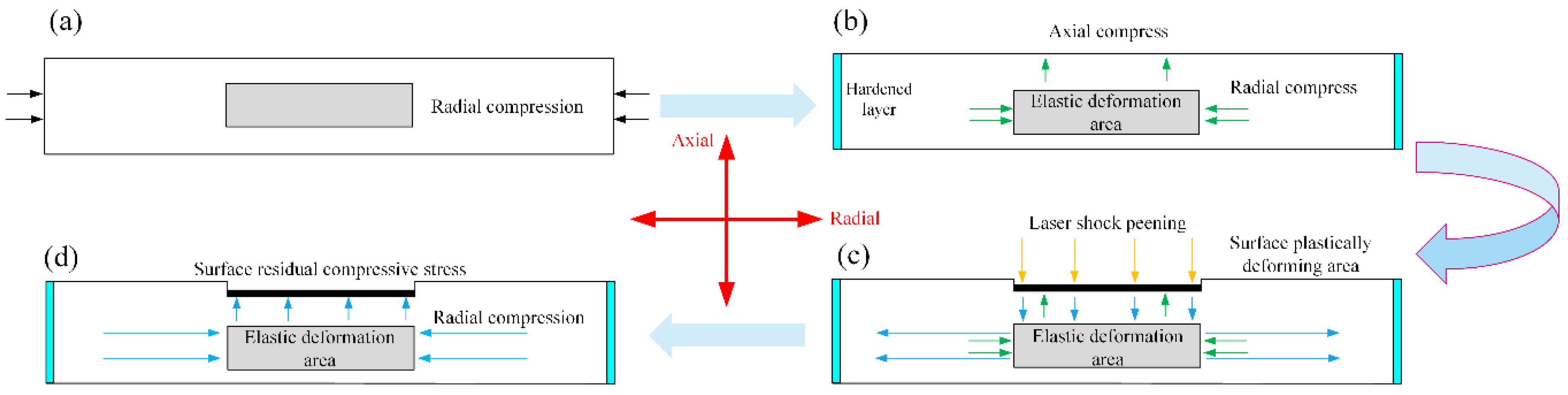
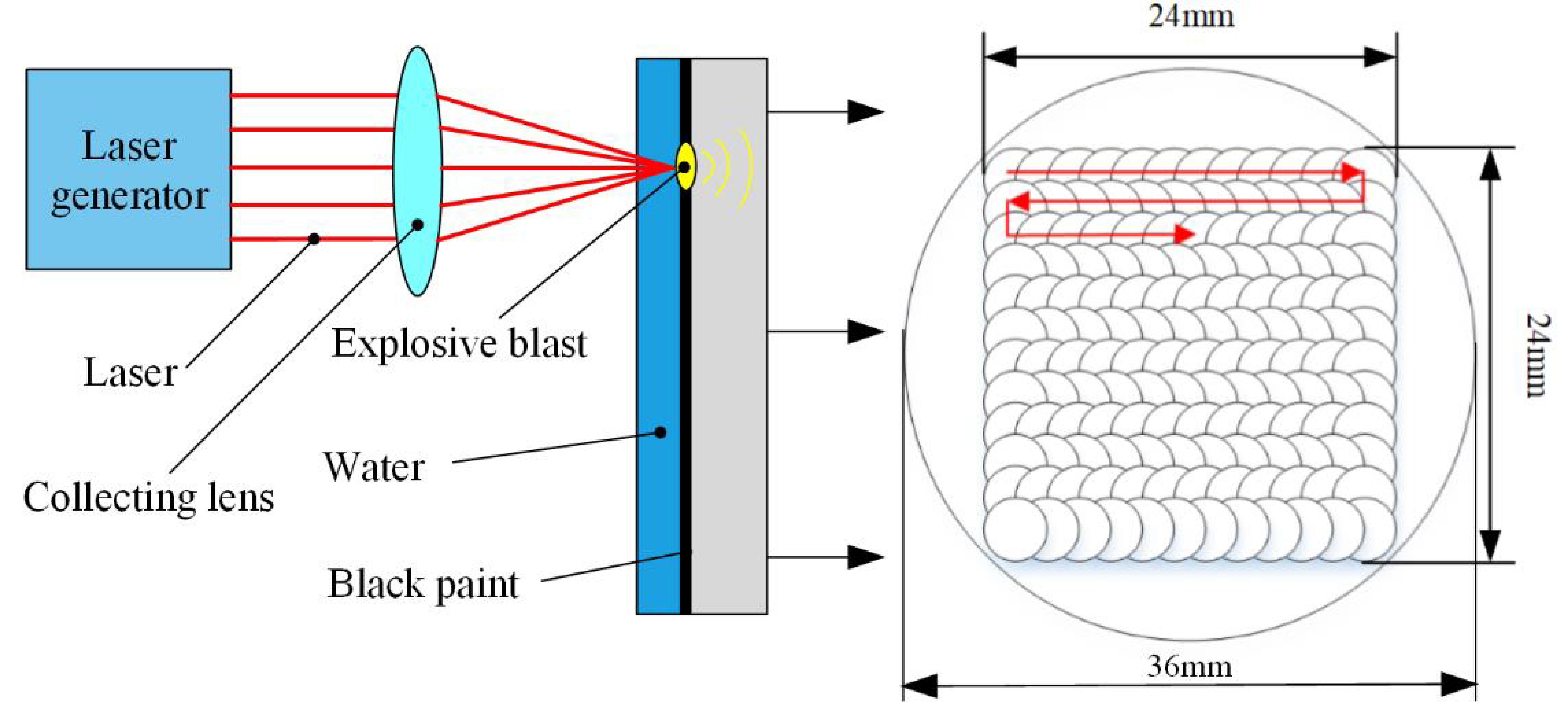
2.2. Laser Shock Peening Process

Laser shock peening was performed in the axial direction at the region of a 24 × 24 mm2 by laser shock peening complete equipment (YS80-M165, Xi’an Tyrida Optical Electric Technology Co, Xi’an, China). The wavelength, maximum output energy, and pulse duration of the laser were 1064 nm, 8 J, and 20 ns, respectively. Table 2 exhibits detailed parameters of the experiment. The laser shock peening areas need to be covered with two different layers. The ablative layer, adhered to the material surface, is black paint. And the constraint layer, attached to the black paint, is water flow with a thickness of 1 mm. Laser beams from the laser generator irradiate and focus on the black paint on the surface material at a pulse duration of 20 ns and a light spot diameter of 4 mm. Lacquers absorb the laser energy and gasify to produce plasma in a short period. Afterward, plasma continues to absorb energy before the end of the pulse time and creates an explosive shock wave. Finally, the shock wave generates plastic deformation on the surface of the material under the action of the restraint layer. Figure 1 depictes the schematic diagram of laser shock peening and the pattern of the laser impact path.

2.3. Surface Characterization

The morphology and roughness on the surface of original magnesium alloy ZK60 and other three samples after laser shock peening were observed and measured by white-light interferometer (USP-Sigma, Saint Louis, MO, USA). An X-ray residual stress analyzer (iXRD MG40, Proto, Oldcastle, ON, Canada), operating at a tube voltage of 20 KV and tube current of 5 mA, was employed to examine the changes of residual stress on the surface using Cr target Kα irradiation. Furthermore, the residual stress was analyzed using a Bragg angle of 138° and a diffraction plane of 202 through the sin2φ method. The exposure time was 2 s, and the collimator diameter was 2 mm. The same location was measured five times and the average was taken as a result. The surface of all samples was etched with corrosive liquid (oxalic acid—1 g, acetic acid—1 mL, nitric acid—1 mL, distilled water—150 mL) for the 20 s after polishing the mirror. Then, the microstructure was observed using an optical microscope (4XC, Shanghai optical instrument factory, Shanghai, China). A scanning electron microscope (SEM, JSM-7610F, JEOL, Tokyo, Japan) based on secondary electron imaging technology was utilized to observe the corrosion morphology, and an energy dispersive spectrometer (EDS, JSM-7610F, JEOL, Tokyo, Japan) was used for elemental analysis of the surface. An X-ray diffractometer (D8-ADVANCE, Bruker, Karlsruhe, Germany) was utilized to distinguish the phase transition before and after LSP and determine the composition of the corrosion products. The tube voltage and tube current were set at 40 KV and 40 mA, respectively.

2.4. Simulated Body Fluid Immersion Testing

SBF solution immersion corrosion testing was implemented to evaluate the corrosion resistance of the untreated sample and modified samples. Simulated body fluid (pH = 7.4–7.5) was applied as a testing medium due to its constituents being similar to blood plasma. Table 3 lists the ingredients and ion concentrations of the SBF solution (Xi’an hutt biotechnology co. LTD, Xi’an, China). Referring to the criterion of GB10124, the solution dosage should not be less than 20 mL for every 1 cm2. The non-working surface of four samples was sealed with Kraft silicone rubber. Afterward, the diced cube samples of 1 cm2 were soaked into a 30 mL solution and then placed into a thermostatic water bath (XMTE-206, Changzhou, China) at 37 ± 0.1 °C. The corrosion resistance testing continued for ten days, and the SBF solution was updated every two days interval to keep fluids fresh and simulate the real environment of an in vivo situation. Meanwhile, to calculate the corrosion rate, all of the samples that have been taken out were ultrasonically cleaned in deionized water for 10 min—after that, the cleaned samples were palced in a drying oven to dry for 20 min. The mass loss of four samples due to corrosion was weighed by an electronic analytical balance whose accuracy was 0.1 mg. The corrosion rate was calculated according to Equation (1). Each SBF immersion experiment was repeated at least two times in the same manner.
V = m 0 m 1 s t
where V refers to the rate of corrosion, m0 is the mass before corrosion, m1 represents the mass after corrosion, and s and t are the surface area corroded and the corrosion time, respectively.

2.5. Electrochemical Corrosion Testing

The electrochemical characteristics of samples with different laser power densities in the SBF solution were investigated by an electrochemical workstation (CHI604E, Shanghai Chenhua Instruments Co., Ltd., Shanghai, China) at 37 ± 0.1 °C. Figure 2 shows the physical connection diagram of an electrochemical workstation. This experiment applied the classical three-electrode system. A saturated calomel electrode was used as a reference electrode, the platinum plate was used as an auxiliary electrode, and the specimen was used as a working electrode. Before the experiment, all specimens were cut into standard cube samples with a dimensions of 10 mm × 10 mm × 5 mm. An aluminum conductive strip was glued to the back of each sample. Simultaneously, the working surface was required to be exposed to SBF solution, and other surfaces were fully wrapped by Kraft silicone rubber to minimize unforeseen effects. Then, we put the connected device in Figure 2 into a constant temperature water bath and kept it at 37 ± 0.1 °C for 30 min to eliminate some external interference and stabilize the open circuit potential. Afterward, the potentiodynamic polarization curve was measured with a scan rate of the tests of 10 mV/s. Meanwhile, to obtain a relatively complete polarization curve, the initial electric potential and final electric potential were set to −1.6 V and −0.9 V, respectively. The analysis software recorded experiment data. Corrosion current density (Icorr) and corrosion potential (Ecrro) were calculated according to the polarization curve by software (CHI604E Electrochemical Analyzer, version 15.03, 3700 Tennision Hill Drive Austin, Austin, TX, USA).

3. Results and Discussion

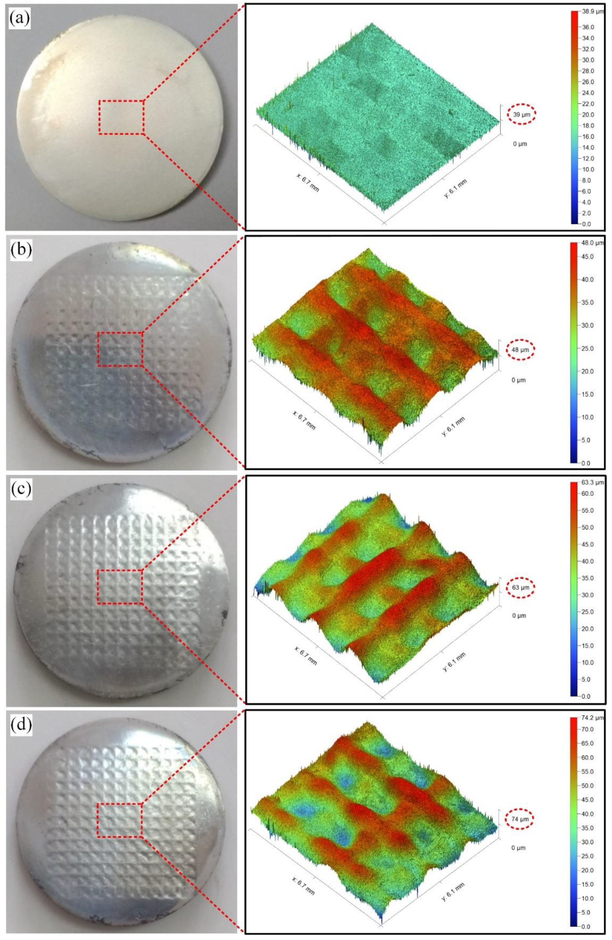
3.1. Surface Topography and Roughness

Figure 3 displays the macroscopic features and 3D morphology on the surface of the samples before and after laser shock peening. As can be seen intuitively in the picture, the surface of the untreated sample is relatively flat, while there are many small dents on the surface of the LSP samples, and the plastic deformation is visible. The peak-to-valley value is one of the surface integrity parameters. Within the parameters studied, there is a distinct tendency of augmenting with the laser power density increment in terms of peak-to-valley value. Besides, roughness is another crucial surface integrity parameter. The surface roughness of the untreated sample was 0.2 µm. However, the surface roughnesses of samples treated by laser using parameters of 1.19 GW/cm2, 1.99 GW/cm2, and 2.79 GW/cm2 were 2.39 µm, 5.68 µm, and 6.11 µm, respectively.
The surface roughness increases linearly with the increasing of laser power density. That is because the mechanical effect of the laser generates plastic deformation. When the peak pressure of the laser exceeds the dynamic yield strength of the material surface, permanent plastic deformation will be caused. The higher the peak pressure is, the more severe the distortion will be, whereas roughness reflects small spacing between the surface and the unevenness of the tiny peaks and valleys. Thereby, the surface roughness increases with the increase of plastic deformation. What is more, the surface roughness of bone integration materials can affect the cell response of osteoblasts. Suitable surface roughness and peak-to-valley values are conducive to the cell adhesion and growth of bone tissue [22]. Hence, as the characteristic surface parameters, surface roughness and peak-to-valley value can be serve as the indexes to evaluate the biocompatibility of bone-implant material. Nevertheless, the exact surface characteristics needed for bone tissue growth are unclear.

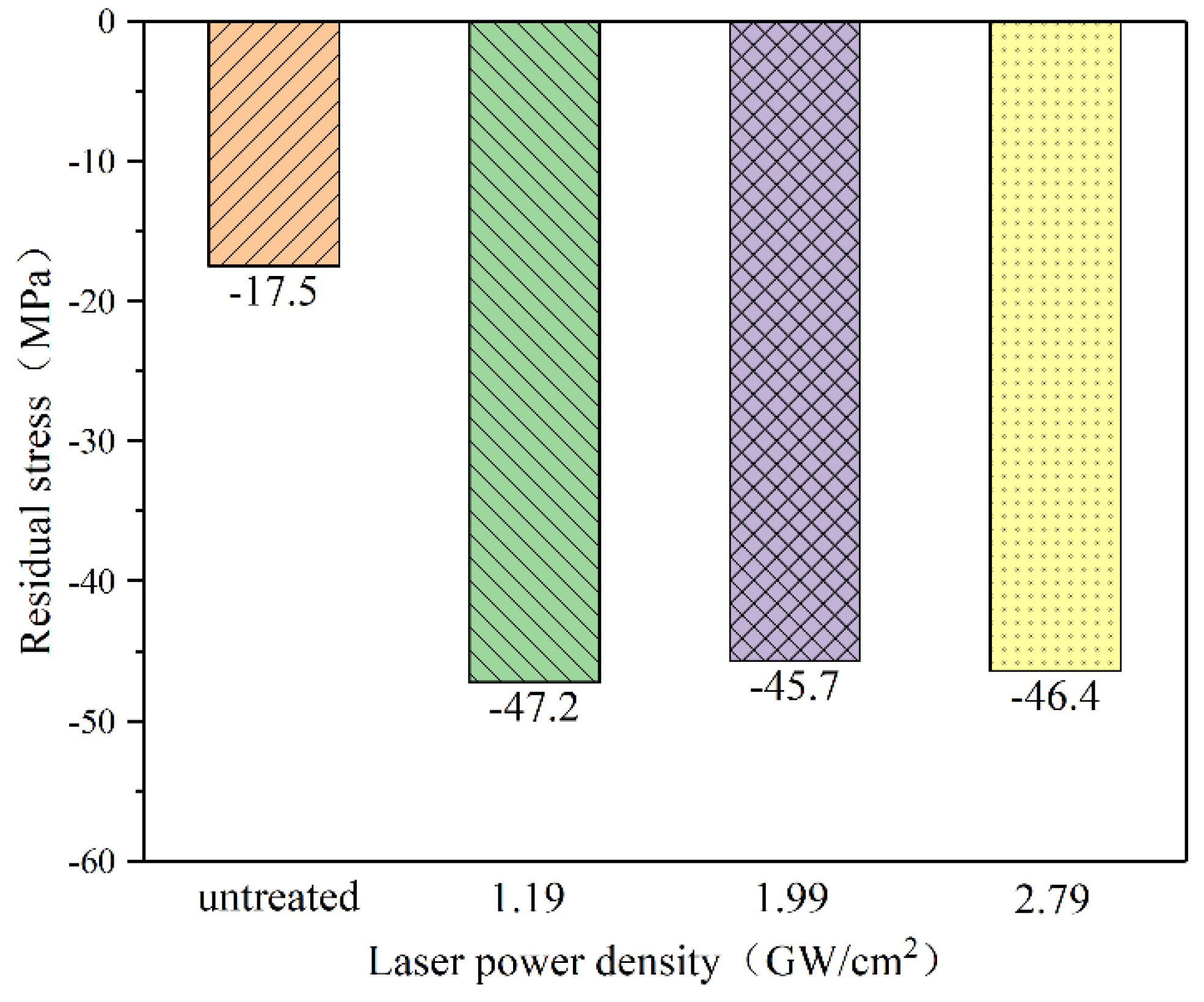
3.2. Residual Stress
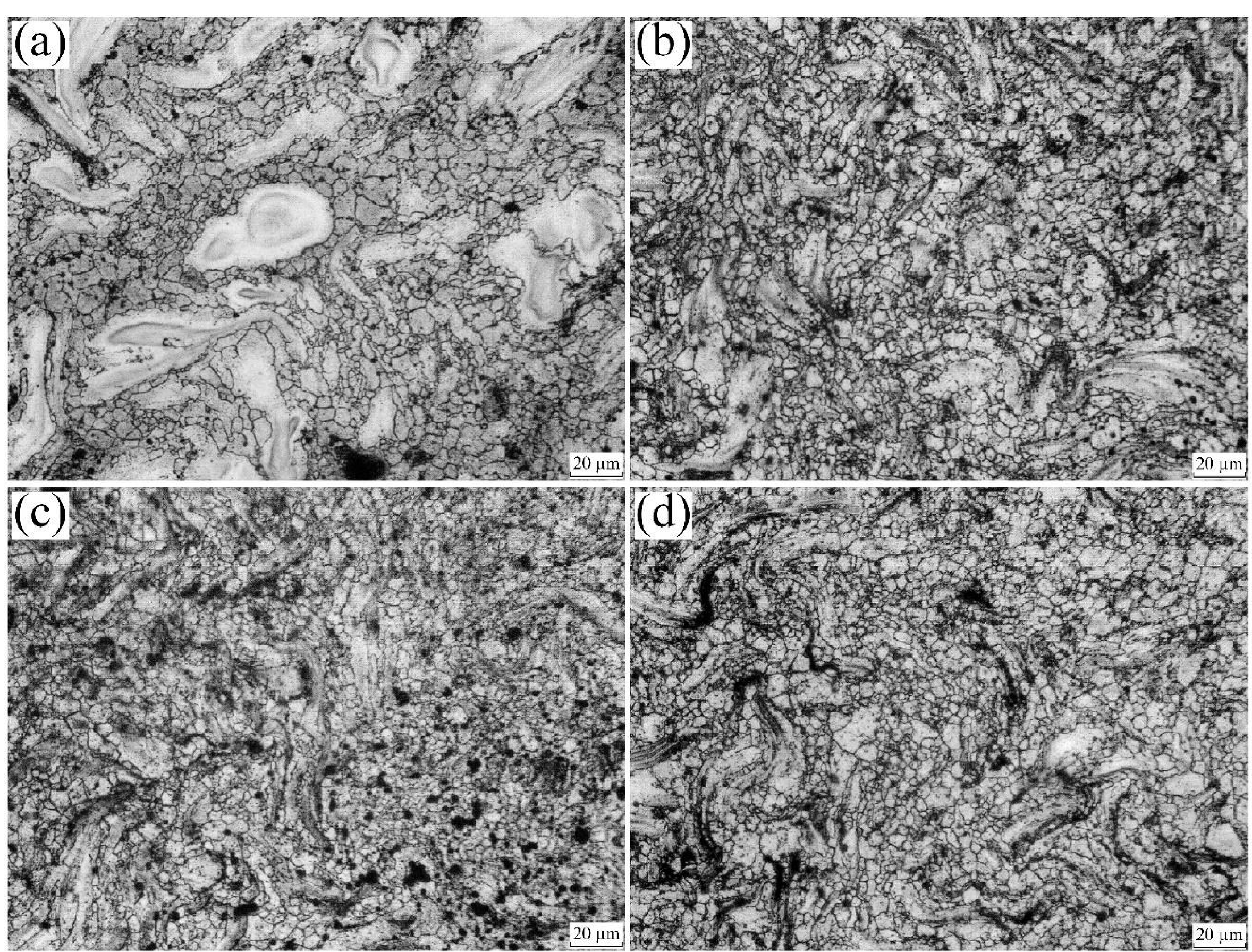
Figure 4 represents the average residual stress values for the four sample surfaces. Based on information conveyed from the picture, the magnitude of the residual compressive stress can be ranked as follows: 1.19 GW/cm2 > 2.79 GW/cm2 > 1.99 GW/cm2 > untreated sample. Generally speaking, the values of residual compressive stress between three treated samples are a little different. The residual compressive stress does not increase with the increase of laser power density. It reaches saturation and stabilizes around –46 MPa. Residual compressive stress is enhanced by a maximum of 1.7 times compared with the original sample. It can be explained that the residual compressive stress will decrease when the shock wave load exceeds 2.5VHEL (Hugoniot elastic limit) [23]. Samples by laser shock peening obtained the higher residual compressive stress compared with the untreated samples, but not by much. Possible reasons can be demonstrated in Figure 5. On the one hand, extruded magnesium alloy was chosen as the raw material in this study. As depicted in Figure 5a,b, the internal grains were subjected to radial pressure in the manufacturing process, and the plastic deformation in the radial circumference produces a hardening layer and induces residual compressive stress. The grains in the plastic deformation zone make the grains with internal elastic deformation bear radial compressive stress and axial tensile stress. Thus, the grains on the upper surface bear compressive stress. Therefore, the original magnesium alloy ZK60 shows the residual compressive stress value of −17.5 MPa.
On the other hand, as shown in Figure 5c, the compressive stress generated by the laser shock wave on the surface grain is opposite to the axial tensile stress in Figure 5b when the laser shock peening is carried out. As a result, the laser shock wave pressure attenuates. And then, laser shock waves after attenuating can still make the surface grain produce plastic deformation, so the grain of plastic deformation area generates axial compressive stress and radial tensile stress on the elastic deformation area’s grain. This tensile stress and the radial compressive stress of Figure 5b are in opposite directions, but the value is more significant, so parts of attenuation are inevitable. The force between grains in the elastic deformation zone and the plastic deformation zone is an interaction force due to they are in contact with each other. The grains in the elastic deformation zone have axial compressive stress on the grains in the plastic deformation zone, which is manifested as residual compressive stress of −46 MPa. The final stress state after the laser shock intensification is shown in Figure 5d.
What is more, as is known to all, among many magnesium alloys, magnesium alloy ZK60 is the material with the highest strength. The higher the strength is, the stronger its resistance to plastic deformation will be, and the less likely it will be to strain. It is one of the reasons why residual compressive stress was not so enormous. Nevertheless, any variation of the remaining stress field on the surface caused by plastic deformation can significantly affect the corrosion performance.

3.3. Microstructure

Figure 6 shows the changes in optical microstructure before and after laser impact. It can be seen from Figure 6a that the size of grains on the surface of the untreated sample is not uniform. It can be observed that there are many large grains in which the scale ranges from 50 μm to 70 μm. Furthermore, the surface grains are refined after laser impact, and the number of grain boundaries increased. To be more exact, according to the results of metallographic analysis software, the average areas of the grains in Figure 6a–d are 45 μm2, 20 μm2, 31 μm2, and 17 μm2, respectively. The grain refinement degree of three laser-treated samples is not very different, which is one of the reasons why the residual stress is not very different. In the meantime, we also found an interesting phenomenon: it may be that the black matter of the second phase has a specific line orientation after laser impact. Its shape changes from a regular circular point (Figure 6a) to a curved meteor shape (Figure 6d). That may be related to the plastic deformation caused by laser shock peening.

3.4. Corrosion Behaviour

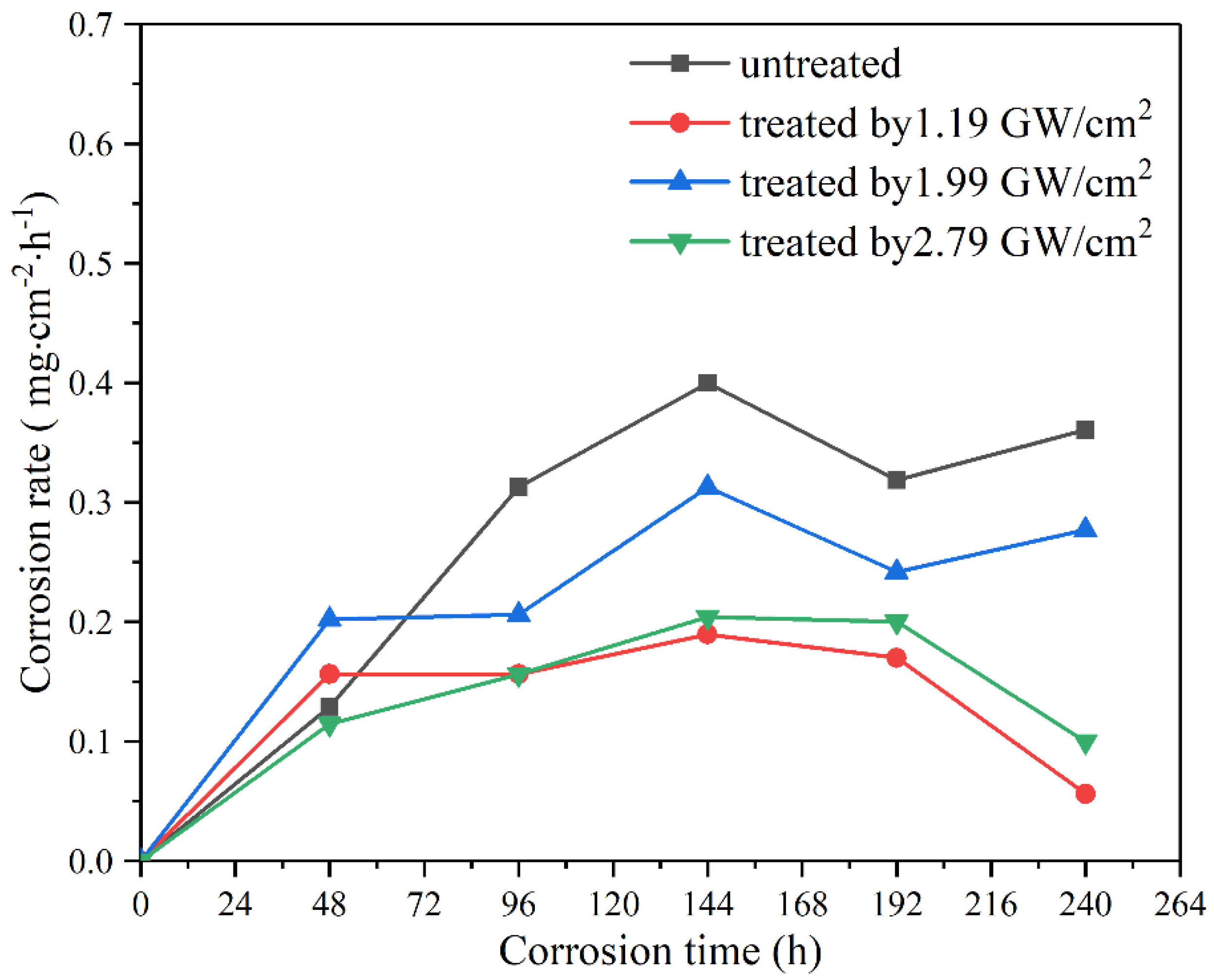
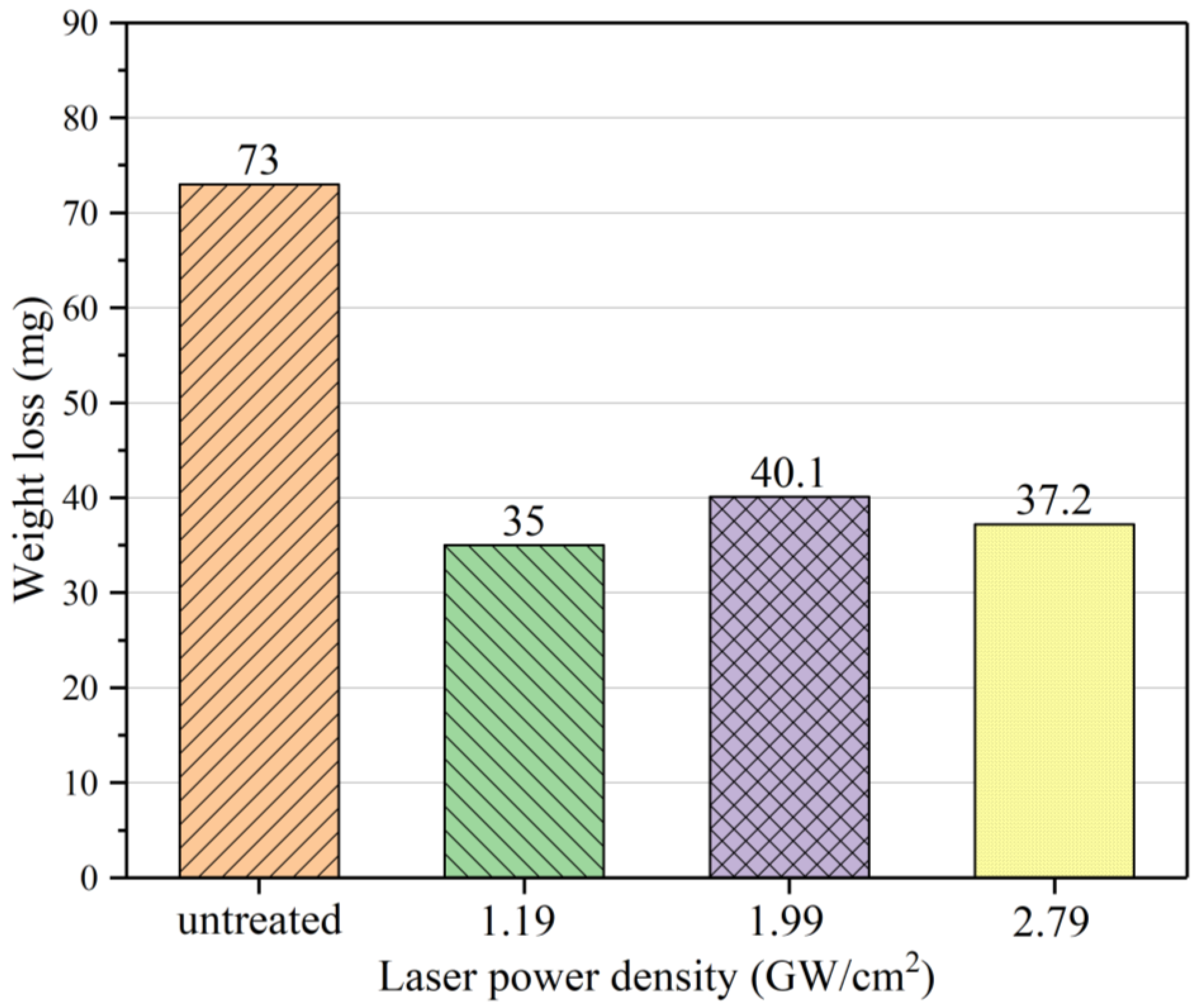
3.4.1. Degradation Rate and Weight Loss

Figure 7 and Figure 8 show the corrosion rate and total weight loss of four samples immersed in SBF for ten days. According to the results of SBF immersion corrosion testing, the corrosion rate of the untreated sample increased linearly within 0–96 h and stabilized at 0.32–0.45 mg·cm−2·h−1 within the ensuing 96–240 h. Whereas, the corrosion rate of the samples treated with 1.19 GW/cm2, 1.99 GW/cm2, and 2.79 GW/cm2 increased within 0–48 h, and stabilized at 0.05–0.2 mg·cm−2·h−1, 0.2–0.32 mg·cm−2·h−1, and 0.05–0.2 mg·cm−2·h−1 in the subsequent 48–240 h, respectively. It worth noting that the corrosion rate of the untreated sample was lower than those of 1.19 GW/cm2 and 1.99 GW/cm2 in the initial stage of 0–48 h, which can be ascribed to a different area due to plastic deformation. Another total weight loss after ten days of untreated sample reached at 73 mg, while weight losses of 1.19 GW/cm2, 1.99 GW/cm2, and 2.79 GW/cm2 were for 35 mg, 40.1 mg, and 37.2 mg correspondingly. In terms of weight loss, the corrosion resistances of three samples treated by 1.19 GW/cm2, 1.99 GW/cm2, and 2.79 GW/cm2 wer improved by 52.1%, 45.1%, and 49%, respectively. Corrosion rate and weight loss of samples treated by laser shock peening were decreased compared with the untreated samples. Among them, the corrosion rate and weight loss of the sample treated with the parameter of 1.19 GW/cm2 were the lowest, followed by the one with the parameter of 2.79 GW/cm2 and the one with the parameter of 1.99 GW/cm2. That is in the same order as the residual compressive stress on the surface of each sample. It can be seen that the residual compressive stress on the surface induced by laser shock intensification shows a positive influence on corrosion resistance.

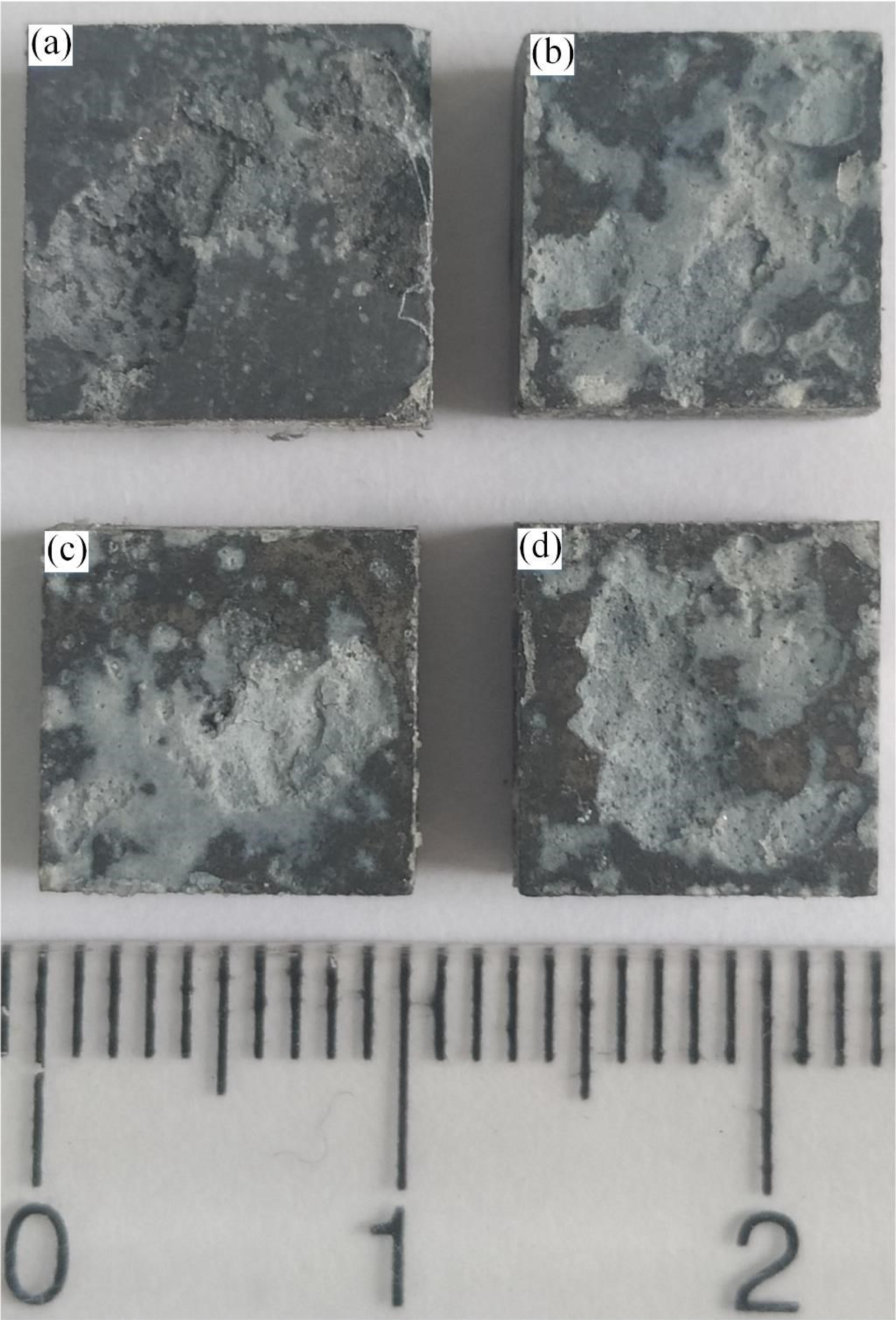
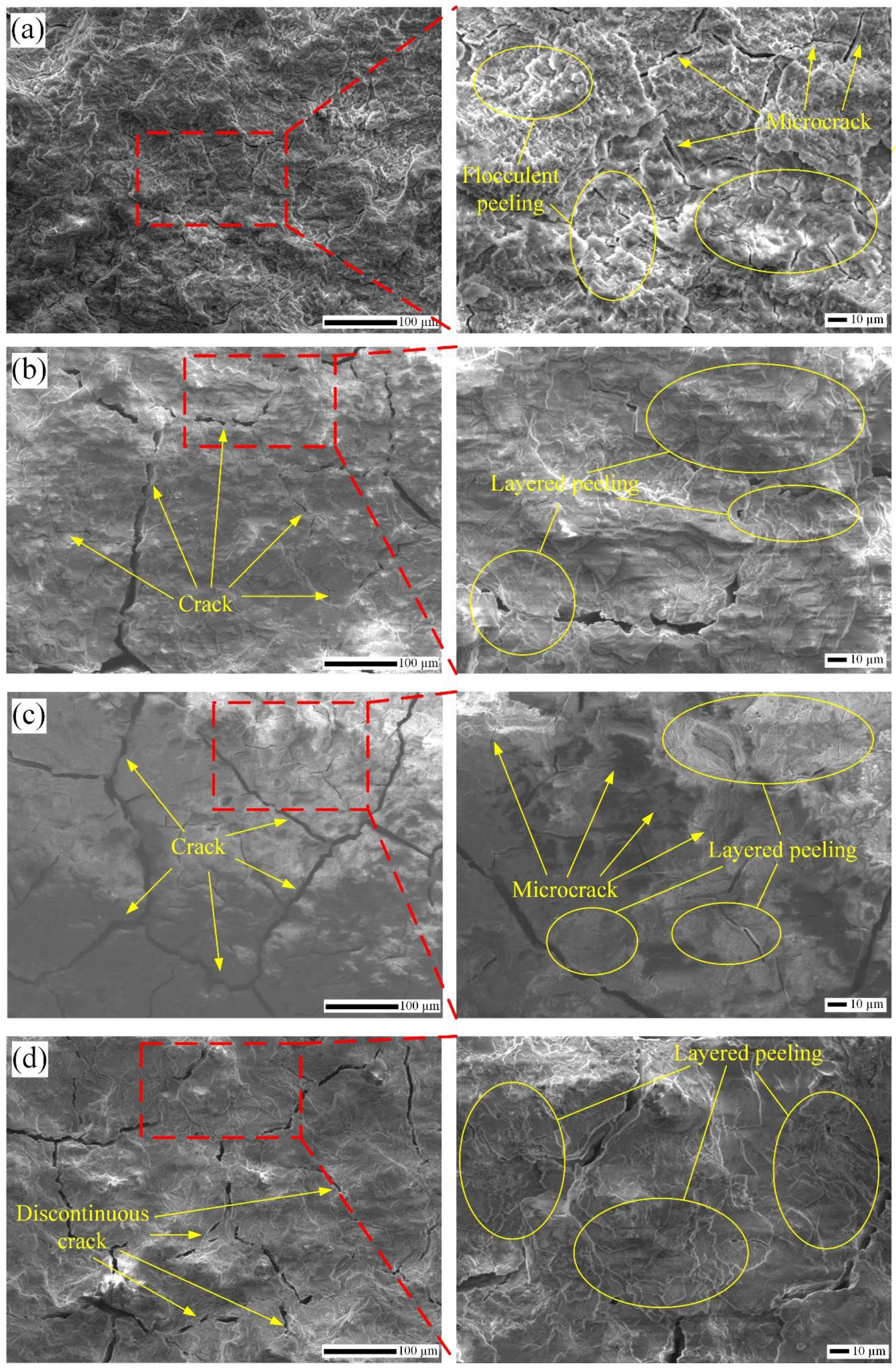
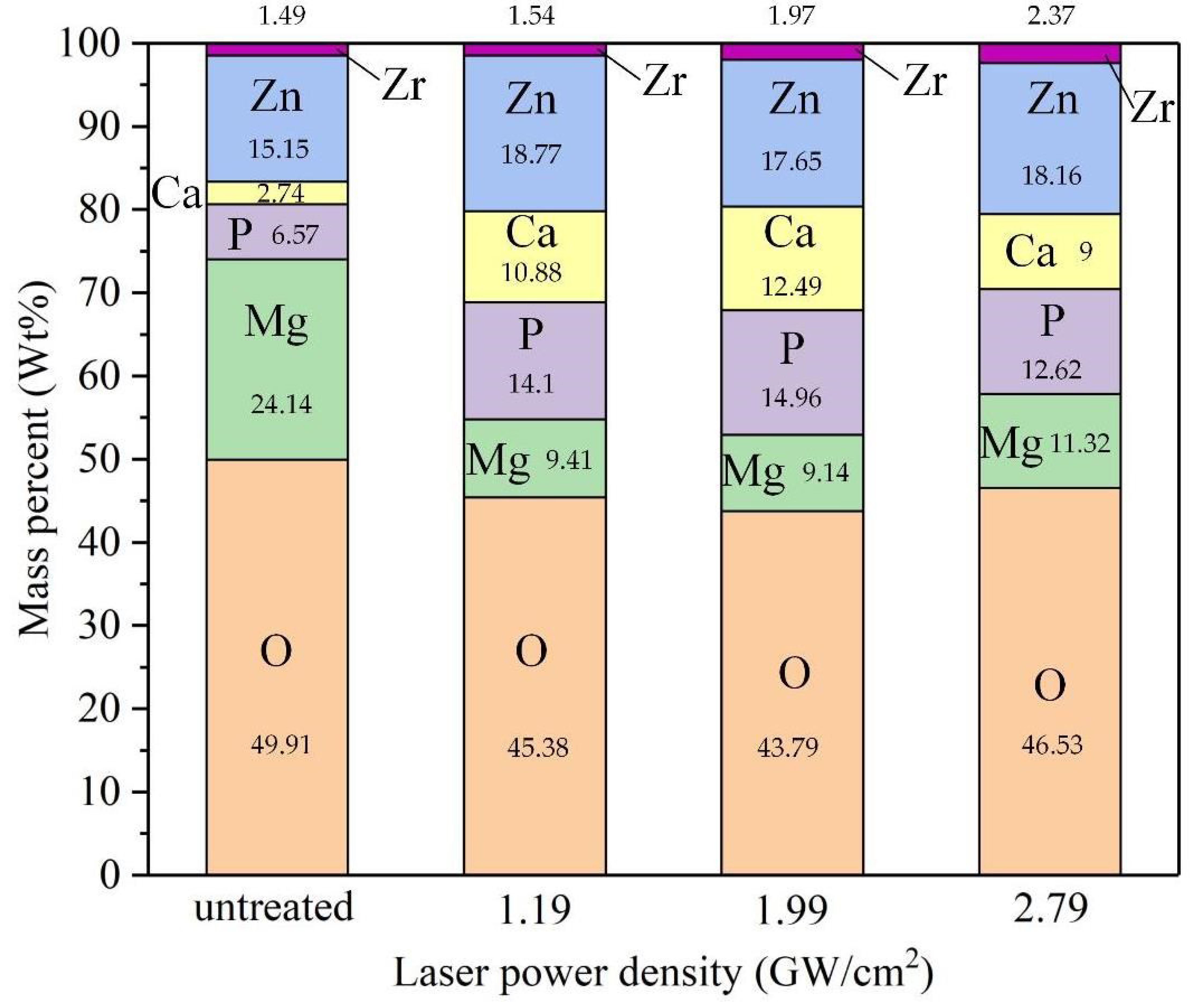
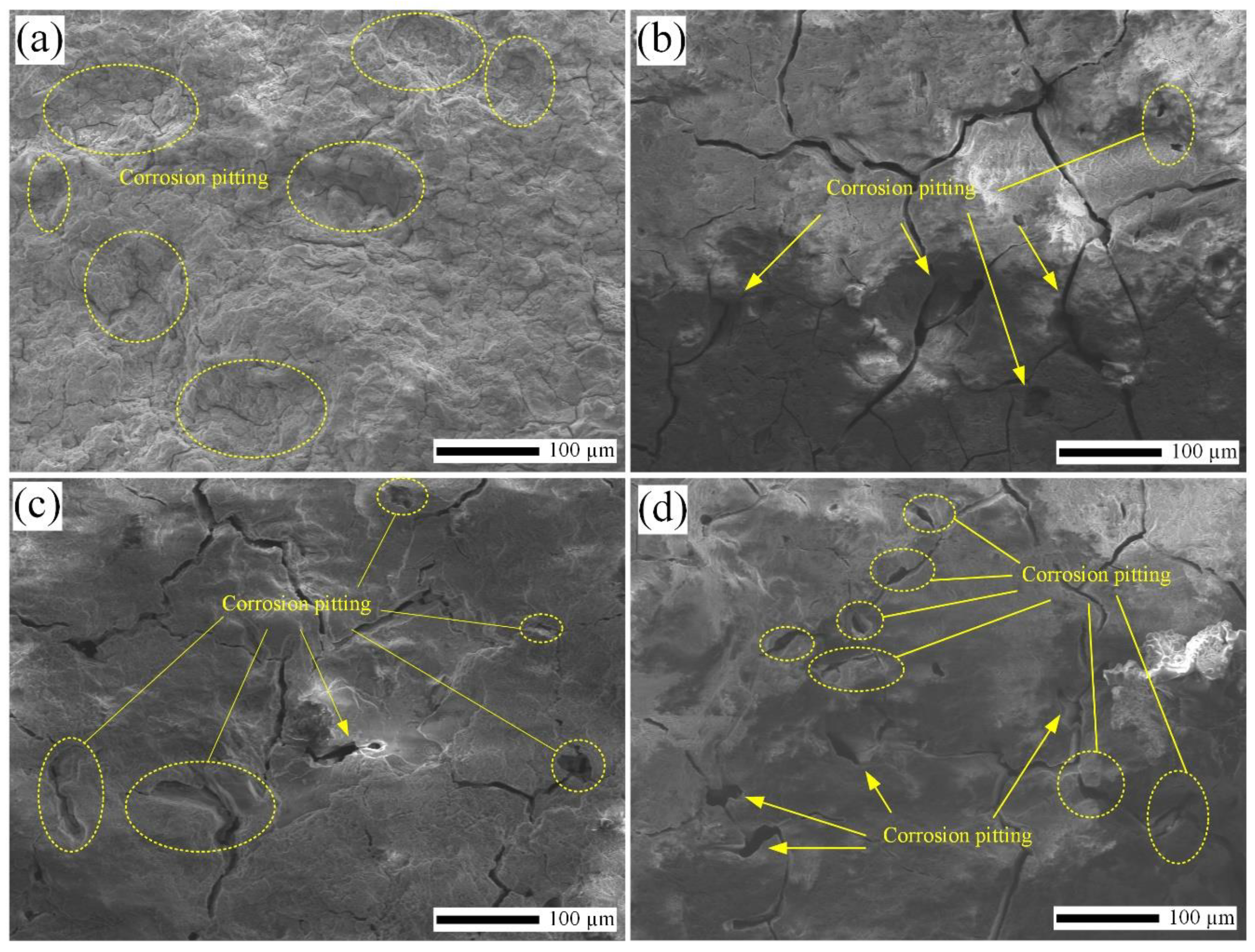
3.4.2. Corrosion Morphology Analysis

Figure 9 shows the macroscopic corrosion appearance of each sample after ten days. Broad and deep corrosion pits appeared on the surface of the original sample, and the corrosion behaviors are more severe in SBF. However, scattered and small corrosion pits appeared on the surface of the three specimens after laser impact. Meanwhile, it was noticed that the depths of pits of Figure 9b–d are less than in Figure 9a. Besides, many visible corrosion pitting pits can also be visually observed in Figure 9b–d. SEM diagrams of the corroded surface under the 100× and 500× lenses are presented in Figure 10. As can be seen in Figure 10a, when the magnification factor is 100×, it can be observed that there are many cracks and uneven places on the surface of the untreated sample with poor surface integrity. With further magnification to 500×, we can see the corrosion of the matrix morphology as numerous flocculent corrosion pits. Besides, too many micro-cracks have also been observed. Compared with Figure 10a, the three samples impacted by a laser had higher surface roughnesess and better surface integrity in the corroded area under the magnification factor of 100×. More importantly, by longitudinal comparison, we can see that the number of cracks on the surface of laser peening samples is significantly reduced under the same magnification factor (100×). The number of cracks on the corroded surface of the sample treated with the parameter 1.19 GW/cm2 is the least, and the large cracks are discontinuous. What is more, the microcracks have not yet broken the corrosion surface into small areas. In Figure 10c, the number of large cracks and micro-cracks increases significantly. Meanwhile, the area surrounded by the cracks was also small. In Figure 10d, a similar number of large cracks can be observed, as in Figure 10c. Still, these large cracks are discontinuous, and there are no tiny cracks, which proves that the sample can significantly inhibit the initiation and propagation of cracks due to residual compressive stress induced by laser shock peening. When enlarging the red area from 100× to 500×, we can see by longitudinal comparison that the corrosion morphology of three samples after laser shock peening is characteristically stratified, which is very different from the flocculent surface of untreated sample.
As a consequence, we can infer that the untreated sample is mainly large particles that flake in the process of corrosion, and the samples after laser shock peening peel off in the form of a skinny and small sliced layers in the corrosion process. This difference is mainly attributed to the fact that the laser causes plastic deformation on the material surface, refines the grain, and introduces the residual compressed stress. According to the above analysis, the sample surface quality of 1.19 GW/cm2 is the best, followed by 2.79 GW/cm2 and 1.99 GW/cm2, which is also consistent with the results of residual compressive stress, corrosion rate, and weight loss on the surface.
Corrosion surface elemental mass percentages from the EDS spectra results of the four samples are collected in Figure 11. The presence of oxygen and magnesium on the surface of all samples can confirm that the corrosion products are mostly Mg oxides. Compared with the untreated sample, the content of Mg on the corrosion surface of the three specimens after laser treatment is low, indicating that LSP improved the corrosion resistance of the sample in SBF. Thus, the oxidation product of magnesium was reduced. Simultaneously, the depositions of Ca and P elements on the corroded surface increased, which can further enhance biological activity and biocompatibility [24].

3.4.3. Corrosion Mechanism Analysis

Figure 12 shows the SEM photographs of corrosion pitting pits on the surface of magnesium before and after laser shock peening. As is shown in Figure 12a, there are large corrosion pits on the surface of the untreated sample. While smaller corrosion pitting pits on the surface of the laser-treated sample are observed in Figure 12b–d, it is distinctly manifest that the corrosion pitting resistance of magnesium alloy ZK60 can be enhanced by laser shock peening. Additionally, surface cracks run through pitting pits. There are two modes when magnesium alloy ZK60 is corroded in the SBF solution. In the first case, electrochemical corrosion occurs with Mg as the anode and second phase with it as the cathode. We obtained the composition of the samples before and after LSP, and the results of XRD patterns are depicted in Figure 13a. It can be seen that the composition of the sample consists of α-Mg and MgZn2. It also indicates that no new phase transition occurred after LSP. In addition, the position and intensity of the peak changed after LSP. That is because laser shock peening produces additional strain on the material by plastic deformation, which causes an increase in dislocation density, which in turn changes the microstructure and surface residual stress field. The changes in residual stress and grain refinement in Figure 4 and Figure 6 may be responsible for the differences in diffraction peaks. Another possible scenario is that with Mg as the anode material and the impurity elements such as Fe and Cu as a cathode, that constitutes micro battery and leads to galvanic corrosion on the surface of magnesium alloy. Figure 13b shows the XRD patterns of the surface after corrosion. The corrosion products on the surface are mainly Mg(OH)2, MgO, and MgCl2. The anode and the cathode reaction, is shown in chemical Equations (2)–(4).
Mg→Mg2+ + 2e
2H2O + 2e → H2 + 2OH
Mg2+ + 2OH → Mg(OH)2
The hydroxide film on magnesium is less stable than passive films from stainless steel and aluminum [25]. In chloride-rich SBF solution, chloride ions induce pitting through the destruction of the passivation film by the following reactions.
Mg(OH)2 + 2Cl → MgCl2 + 2OH
Other, heavy metals in ZK60 can also promote pitting corrosion [25]. When pitting occurs, hydrogen tends to gather in the defected part of the material (corrosive pitting pits) to weaken the atomic bonding of the material matrix and causes hydrogen embrittlement [26]. Meanwhile, stress concentration is natural to occur in corrosive pitting pits, so the crack initiation occurs through corrosive pitting. It can reasonably explain the contact between corrosion pitting pits and corrosion cracks in Figure 12b–d. At the same time, Zinc element in ZK60 can promote stress corrosion cracking to form cracks in a neutral solution containing chloride [25]. Firstly, the improvement of corrosion resistance is related to the refinement of surface grain after laser shock peening. That is because the smaller the grain size is, the more grain boundaries there will be. Grain boundaries can act as physical corrosion shielding to prevent corrosion; as a consequence, the corrosion rate will be reduced [27]. Secondly, the corrosion resistance of the sample is also connected with the passivation film. The increase of residual compressive stress on the surface of the sample will make the passivation film denser. Under the action of higher compressive stress, the passivation film is unlikely to fall off [28].

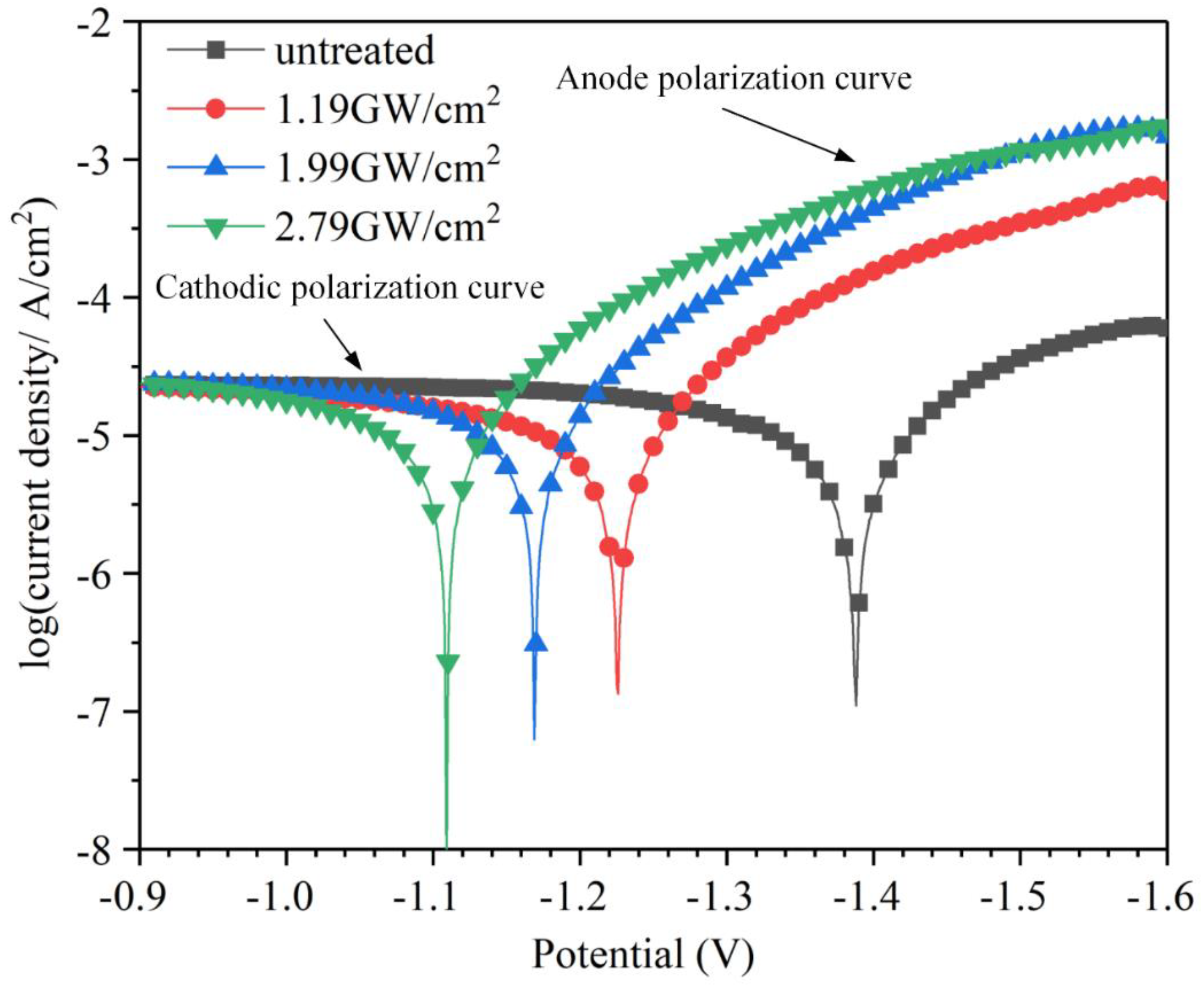
3.5. Electrochemical Analysis

The standard electrode potential of magnesium is −2.37 V, which makes magnesium chemically active, and any method that can increase its potential has reference significance. Therefore, it is necessary to study the electrochemical properties of magnesium alloy ZK60 in SBF after laser shock peening. Potentiodynamic testing was conducted to original magnesium alloy ZK60 and laser impacted samples in the SBF solution. The polarization curves of the four samples are recorded in Figure 14. Simultaneously, corrosion current density and corrosion potential are correspondingly summarized in Table 4. The experimental results reveal that the corrosion potential positively shifts after LSP, and the value of corrosion current density is less than the untreated one. Thereinto, the corrosion voltages of untreated, 1.19 GW/cm2, 1.99 GW/cm2, and 2.79 GW/cm2 were −1.3884 ± 0.04 V, −1.2256 ± 0.03 V, −1.1707 ± 0.05 V, and −1.1094 ± 0.03 V, respectively. The maximum offset of corrosion potential was 217.7 mV. Meanwhile the corrosion current densities were equal to 1.378 × 10⁻⁵ A/cm2, 1.267 × 10⁻⁵ A/cm2, 1.23 × 10⁻⁵ A/cm2, and 1.196 × 10⁻⁵ A/cm2, respectively. The increase in laser power density resulted in a maximum increase in corrosion potential of 20.1% and a maximum reduction in corrosion current density of 13.2%. It can be seen that LSP can improve the corrosion potential of magnesium alloy ZK60 and reduce the corrosion current density. The corrosion potential increases with the increase of laser power density, and the change trend of corrosion current density is the opposite. This is mainly due to the increase in residual compressive stress and grain refinement.

4. Conclusions

The effects of laser power density on the surface morphology, surface roughness, residual stress, and corrosion behavior of biocompatible magnesium alloy ZK60 were investigated. The following conclusions can be summarized:
(1)
Plastic deformation increases with the increase of laser power density, which increases the value of surface roughness from the initial 0.2 µm to 6.11 µm.
(2)
LSP changes the surface residual stress field of magnesium alloy ZK60. The surface residual stress does not increase with the laser power density increases. When the laser power density is 1.19 GW/cm2, 1.99 GW/cm2, and 2.79 GW/cm2, the surface residual stress can be increased up to 47.2 MPa, 45.7 MPa, 46.4 MPa, respectively. Residual compressive stress is enhanced by a maximum of 1.7 times compared with the original sample. LSP can refine the size of the grains, and the average area of the surface grains decreases approximately as the power density increases. The average grains area falls from 45 μm2 to 17 μm2.
(3)
The degradation rate of magnesium alloy ZK60 in the SBF solution is decreased after LSP owing to a denser passivation film induced by higher residual compressive stress and grain refinement. In terms of the total weight loss, corrosion resistance increased by 52.1%, 45.1%, and 49%, respectively.
(4)
Corrosion cracks originate from corrosion pitting pits due to the influence of hydrogen embrittlement and stress concentration. Modified samples can improve corrosion pitting resistance and restrain crack initiation and propagation. The increase of calcium and phosphorus deposition is beneficial to improving the biocompatibility further.
(5)
Electrochemical experiments show that the corrosion potential increased from −1.3884 V to −1.1094 V, and the current density decreased from 1.378 × 10⁻⁵A/cm2 to 1.196 × 10⁻⁵A/cm2. The corrosion tendency decreased by 20.1% in maximally.
(6)
To summarize, when the power density is 1.19 GW/cm2, the magnesium alloy ZK60 can obtain superior corrosion resistance in the SBF solution.

Author Contributions

Software, Z.S.; validation, S.W., W.L., and Y.G.; formal analysis, investigation, data curation, and writing—original draft preparation, Y.G.; resources, S.W.; writing—review and editing, W.L.; visualization, G.Z.; supervision, T.X.; project administration and funding acquisition, S.W.

Funding

This research was funded by the National Natural Science Foundation of China, grant number 51872122; the Shandong Key Research and Development Plan of China, grant number 2016JMRH0218 and 2017CXGC0809; and Taishan Scholar Engineering Special Funding (2016–2020).

Conflicts of Interest

The authors declare no conflict of interest.

References

  1. Zeng, R.; Dietzel, W.; Witte, F.; Hort, N.; Blawert, C. Progress and challenge for magnesium alloys as biomaterials. Adv. Eng. Mater. 2008, 10, B3–B14. [Google Scholar] [CrossRef]
  2. Puleo, D.A.; Huh, W.W. Acute toxicity of metal ions in cultures of osteogenic cells derived from bone marrow stromal cells. J. Appl. Biomater. 1995, 6, 109–116. [Google Scholar] [CrossRef] [PubMed]
  3. Staiger, M.P.; Pietak, A.M.; Huadmai, J.; Dias, G. Magnesium and its alloys as orthopedic biomaterials: A review. Biomaterials 2006, 27, 1728–1734. [Google Scholar] [CrossRef] [PubMed]
  4. Poinern, G.E.J.; Brundavanam, S.; Fawcett, D. Biomedical magnesium alloys: A review of material properties, surface modifications and potential as a biodegradable orthopaedic implant. Am. J. Biomed. Eng. 2012, 2, 218–240. [Google Scholar] [CrossRef]
  5. Denkena, B.; Lucas, A. Biocompatible magnesium alloys as absorbable implant materials-adjusted surface and subsurface properties by machining processes. Cirp Ann. 2007, 56, 113–116. [Google Scholar] [CrossRef]
  6. Radha, R.; Sreekanth, D. Insight of magnesium alloys and composites for orthopedic implant applications—A review. J. Magnes. Alloys 2017, 5, 286–312. [Google Scholar] [CrossRef]
  7. Filli, L.; Luechinger, R.; Frauenfelder, T.; Beck, S.; Guggenberger, R.; Farshad-Amarcker, N.; Andreisek, G. Metal-induced artifacts in computed tomography and magnetic resonance imaging: Comparison of a biodegradable magnesium alloy versus titanium and stainless steel controls. Skelet. Radiol. 2015, 44, 849–856. [Google Scholar] [CrossRef]
  8. Vormann, J. Magnesium: Nutrition and metabolism. Mol. Asp. Med. 2003, 24, 27–37. [Google Scholar] [CrossRef]
  9. Persaud-Sharma, D.; Mcgoron, A. Biodegradable magnesium alloys: A review of material development and applications. J. Biomim. Biomater. Tissue Eng. 2012, 12, 25–39. [Google Scholar] [CrossRef]
  10. Shimizu, Y.; Yamamoto, A.; Mukai, T.; Shirai, Y.; Kano, M.; Kudo, T.; Kanetaka, H.; Kikuchi, M. Medical application of magnesium and its alloys as degradable biomaterials. Interface Oral Health Sci. 2009 2010, 318–320. [Google Scholar] [CrossRef]
  11. Gray, J.E.; Luan, B. Protective coatings on magnesium and its alloys—A critical review. J. Alloys Compd. 2002, 336, 88–113. [Google Scholar] [CrossRef]
  12. Lim, H.; Kim, P.; Jeong, H.; Jeong, S. Enhancement of abrasion and corrosion resistance of duplex stainless steel by laser shock peening. J. Mater. Process Technol. 2012, 212, 1347–1354. [Google Scholar] [CrossRef]
  13. Peyre, P.; Scherpereel, X.; Berthe, L.; Carboni, C.; Fabbro, R.; Béranger, G.; Lemaitre, C. Surface modifications induced in 316L steel by laser peening and shot-peening. Influence on pitting corrosion resistance. Mater. Sci. Eng. A 2000, 280, 294–302. [Google Scholar] [CrossRef]
  14. Caralapatti, V.K.; Narayanswamy, S. Analyzing the effect of high repetition laser shock peening on dynamic corrosion rate of magnesium. Opt. Laser Technol. 2017, 93, 165–174. [Google Scholar] [CrossRef]
  15. Ge, M.Z.; Xiang, J.Y. Effect of laser shock peening on microstructure and fatigue crack growth rate of AZ31B magnesium alloy. J. Alloys Compd. 2016, 680, 544–552. [Google Scholar] [CrossRef]
  16. Guo, Y.B.; Sealy, M.P.; Guo, C.S. Significant improvement of corrosion resistance of biodegradable metallic implants processed by laser shock peening. Cirp Ann. 2012, 61, 583–586. [Google Scholar] [CrossRef]
  17. Zhang, Y.K.; You, J.; Lu, J.Z.; Cui, C.Y.; Jiang, Y.F.; Ren, X.D. Effects of laser shock processing on stress corrosion cracking susceptibility of AZ31B magnesium alloy. Surf. Coat. Technol. 2010, 204, 3947–3953. [Google Scholar] [CrossRef]
  18. Witte, F.; Hort, N.; Vogt, C.; Cohen, S.; Kainer, K.U.; Wilumeit, R.; Feyerabend, F. Degradable biomaterials based on magnesium corrosion. Curr. Opin. Solid State Mater. Sci. 2008, 12, 63–72. [Google Scholar] [CrossRef]
  19. Qi, Z.R.; Zhang, Q.; Tan, L.L.; Lin, X.; Yin, Y.; Wang, X.L.; Yang, K.; Wang, Y. Comparison of degradation behavior and the associated bone response of ZK60 and PLLA in vivo. J. Biomed. Mater. Res. Part A 2014, 102, 1255–1263. [Google Scholar] [CrossRef]
  20. Hong, D.; Saha, P.; Chou, D.T.; Lee, B.; Collins, B.E.; Tan, Z.Q.; Dong, Z.Y.; Kumat, P.N. In vitro degradation and cytotoxicity response of Mg–4% Zn–0.5% Zr (ZK40) alloy as a potential biodegradable material. Acta Biomater. 2013, 9, 8534–8547. [Google Scholar] [CrossRef]
  21. Gu, X.N.; Li, N.; Zheng, Y.F.; Ruan, L. In vitro degradation performance and biological response of a Mg-Zn-Zr alloy. Mater. Sci. Eng., B 2011, 176, 1778–1784. [Google Scholar] [CrossRef]
  22. Kieswetter, K.; Schwartz, Z.; Dean, D.D.; Boyan, B.D. The Role of Implant Surface Characteristics in the Healing of Bone. Crit. Rev. Oral Biol. Med. 1996, 7, 329–345. [Google Scholar] [CrossRef] [PubMed]
  23. Peyre, P.; Fabbro, R.; Merrien, P.; Lieurade, H.P. Laser shock processing of aluminium alloys. Application to high cycle fatigue behavior. Mater. Sci. Eng., A 1996, 210, 102–113. [Google Scholar] [CrossRef]
  24. Chen, J.Y.; Zhang, Z.G.; Ouyang, J.L.; Chen, X.S.; Xu, Z.W.; Sun, X.T. Bioactivity and osteogenic cell response of TiO2 nanotubes coupled with nanoscale calcium phosphate via ultrasonification-assisted electrochemical deposition. Appl. Surf. Sci. 2014, 305, 24–32. [Google Scholar] [CrossRef]
  25. Song, G.L.; Atrens, A. Corrosion Mechanisms of Magnesium Alloys. Adv. Eng. Mater. 1999, 1, 11–33. [Google Scholar] [CrossRef]
  26. Kannan, M.B.; Dietzel, W. Pitting-induced hydrogen embrittlement of magnesium-aluminium alloy. Mater. Des. 2012, 42, 321–326. [Google Scholar] [CrossRef]
  27. Aung, N.N.; Zhou, W. Effect of grain size and twins on corrosion behaviour of AZ31B magnesium alloy. Corros. Sci. 2010, 52, 589–594. [Google Scholar] [CrossRef]
  28. Wu, S.X.; Wang, S.R.; Wang, G.Q.; Yu, X.C.; Liu, W.T.; Chang, Z.Q.; Dao, S.W. Microstructure, mechanical and corrosion properties of magnesium alloy bone plate treated by high-energy shot peening. Trans. Nonferrous Met. Soc. China 2019, 29, 1641–1652. [Google Scholar] [CrossRef]
Figure 1. Schematic diagram of laser shock peening and the pattern of laser impact path.
Metals 09 01237 g001
Figure 2. Physical connection diagram of electrochemical workstation: (a) general connection drawing of electrochemical workstation; (b) enlarged view of connection; (c) schematic diagram of the electrode.
Metals 09 01237 g002
Figure 3. Macroscopic featurse and 3D morphology of surface: (a) untreated; (b) 1.19 GW/cm2; (c) 1.99 GW/cm2; (d) 2.79 GW/cm2.
Metals 09 01237 g003
Figure 4. Statistical diagram of surface residual stresses of the four samples.
Metals 09 01237 g004
Figure 5. Schematic diagram of the internal stress state of materials before and after laser shock peening: (a) during extrusion; (b) end of extrusion; (c) during laser shock peening; (d) end of laser shock peening.
Metals 09 01237 g005
Figure 6. The surface microstructure before and after laser impact: (a) untreated; (b) 1.19 GW/cm2; (c) 1.99 GW/cm2; (d) 2.79 GW/cm2.
Metals 09 01237 g006
Figure 7. Corrosion rate diagram of four samples immersed in SBF within 10 days.
Metals 09 01237 g007
Figure 8. Total weight losses of four samples after 10 days.
Metals 09 01237 g008
Figure 9. Macroscopic corrosion topography after immersion in SBF solution for ten days: (a) untreated; (b) 1.19 GW/cm2; (c) 1.99 GW/cm2; (d) 2.79 GW/cm2.
Metals 09 01237 g009
Figure 10. SEM diagram of corroded surface: (a) untreated; (b) 1.19 GW/cm2; (c) 1.99 GW/cm2; (d) 2.79 GW/cm2.
Metals 09 01237 g010
Figure 11. Elemental mass percentages of EDS spectral results.
Metals 09 01237 g011
Figure 12. SEM photographs of corrosion pitting pits on the surface of magnesium before and after laser shock peening: (a) untreated; (b) 1.19 GW/cm2; (c) 1.99 GW/cm2; (d) 2.79 GW/cm2.
Metals 09 01237 g012
Figure 13. XRD patterns before and after corrosion: (a) The change of phase before and after LSP; (b) XRD pattern of corroded surface.
Metals 09 01237 g013
Figure 14. Potentiodynamic polarization curves of the untreated, 1.19 GW/cm2, 1.99 GW/cm2, and 2.79 GW/cm2 in SBF solution.
Metals 09 01237 g014
Table 1. Chemical components of magnesium alloy ZK60 in wt%.
MgZnZrMnFeCuNi
Bal.6.0270.67580.0060.0050.0060.003
Table 2. Specific parameters of laser shock peening.
NumberEnergySpot DiameterLaser DensityPulse WidthOverlap
13 J4 mm1.19 GW/cm220 ns50%
25 J4 mm1.99 GW/cm220 ns50%
37 J4 mm2.79 GW/cm220 ns50%
Table 3. Composition of simulated body fluid.
CompositionNa+K+Mg2+Ca2+ClHCO3HPO42−SO42−
Content (mM/L)1425.01.52.5103.010.01.00.5
Table 4. The electrochemical parameters of potentiodynamic polarization curves.
SamplesEcorr (V)Icorr (A/cm2)
untreated−1.3884 ± 0.041.378 × 10−5
1.19 GW/cm2−1.2256 ± 0.031.267 × 10−5
1.99 GW/cm2−1.1707 ± 0.051.230 × 10−5
2.79 GW/cm2−1.1094 ± 0.031.196 × 10−5

