Article

Refined Microstructure and Enhanced Hardness in Friction Stir-Welded AZ31 Magnesium Alloy Induced by Heat Pipe with Different Cooling Liquid

1
School of Materials Science and Engineering, Jiangsu University of Science and Technology, Zhenjiang 212003, Jiangsu, China
2
School of Science, Jiangsu University of Science and Technology, Zhenjiang 212003, Jiangsu, China
3
Guangxi Key Laboratory of Processing for Non-ferrous Metals and Featured Materials, Nanning 530004, Guangxi, China
*
Authors to whom correspondence should be addressed.
Metals 2019, 9(11), 1227; https://doi.org/10.3390/met9111227
Submission received: 30 September 2019 / Revised: 9 November 2019 / Accepted: 12 November 2019 / Published: 16 November 2019

Abstract

:
The temperature field in welded plates has a significant influence on the microstructure and thereby their properties during friction stir welding (FSW). In this work, a self-designed heat pipe with different cooling liquid was applied in the FSW process for AZ31 magnesium alloy. The temperature fields, microstructures and properties of the welded joints were investigated. The peak temperatures and the durations of high temperature at both the advancing side and the retreating side decrease during the FSW process after applying the heat pipe and adding the ambient temperature water in the condensing tank. The top part of the weld nugget zone of the joint shows a significant decrease as well as its middle part due to the cooling effect of the heat pipe. The microstructure of the weld nugget zone is refined, associated with the increase in the hardness after applying the heat pipe. When the cooling liquid turns into ice water, grains in the weld nugget zone become significantly smaller and have a more homogeneous size. The mean value of hardness increases and the corresponding deviation is declined. Therefore, these results indicate that the application of the heat pipe and the employment of ice water as the cooling liquid can further refine the microstructure and enhance the strength of the material.

Graphical Abstract

1. Introduction

Magnesium (Mg) alloy is considered as one of the most promising potential metallic materials since it possesses several advantages including low density, high specific strength, excellent thermal conductivity and outstanding electromagnetic shielding [1,2,3,4,5,6]. Therefore, Mg alloys are widely used in the automobile and aircraft industries, especially the Mg–Al–Zn alloys (AZ series). Among them, AZ31 Mg alloys have become among the promising non-ferrous metal materials used in these fields due to the high room temperature strength and resistance to atmospheric corrosion [7,8]. With the increasing applications of Mg alloys in auto parts manufacturing, the welding of different components has gradually attracted people’s attention. However, the poor weldability of Mg alloys is performed due to their special pyroelectric and poor oxidation resistance [9,10]. In particular, conventional welding methods (such as, metal-arc inert gas, plasma arc and tungsten-arc inert gas) may lead to large residual stress, stress corrosion cracking sensitivity and evaporation loss [11]. Moreover, a brittle intermetallic phase (such as β-Mg17Al12) is prone to being formed during the welding process, which leads to the decrease in the mechanical properties of friction stir-welded AZ31 magnesium alloys [12].
Friction stir welding (FSW), which renders two metallic sheets effectively to join together, is a solid welding technique with the advantages of being of low-energy cost and environmentally friendly [13,14,15,16]. In the FSW process, a rotating tool, which consists of an inner concave shoulder and a stirring pin, inserts into the metallic sheets. The stirring pin is a threaded straight cylindrical or tapered tip stretched from the concave shoulder. Then the rotating tool moves forward along the process direction and a softening zone is produced around the stirring pin [17]. The grains are broken up due to the severe deformation that resulted from the friction and stirring. Afterwards, these fragmentized grains are dynamically recrystallized under the influence of heat generated by the friction of the shoulder plates and the pin plates [18,19].
It is well known that the heat produced during the FSW process is not enough to induce the melting of materials but increases the temperature of the processed plates [1,20,21]. However, such a welding process is carried out in air and, thereby, the grains obviously become coarse due to a long-time exposure to the high temperature [22]. In addition, the temperature field represents an asymmetric distribution along the three-dimensional direction owing to the insufficient metal flow in the welding plates, especially along the welding direction (WD) and transverse direction (TD) [23]. In order to optimize the microstructure of the joint, some previous works introduced cooling medium to absorb excessive heat during the FSW process [17,24]. Liu et al. [25] conducted underwater friction stir welding on 2219-T6 aluminum alloy and reported that the improvement in strength of the material is achieved by limiting the growth of grains and restraining the dissolution of precipitates. Ma et al. [26] demonstrated that the softening in the FSW joint is significantly reduced after the application of the cooling water since the grains in the weld nugget zone (WNZ) are considerably refined. Wang et al. [27] reported that the thermal gradient of the processed plates significantly decrease along the thickness of joint after applying liquid nitrogen on its top surface. Compared with the counterpart with no cooling condition, the material under the rapid cooling condition showed finer and more homogeneous equiaxed grains in the microstructure. Xu et al. [28] conducted the FSW process by the application of additional liquid CO2 cooling. The results showed that the cooling rate of the joint significantly increases and, hence, ultra-fine grains with high-density dislocations are presented in the welding zone. Ramaiyan et al. [29] conducted submerged friction stir processing and cryogenic cooling friction stir processing on AZ31 alloys. The results showed that the peak temperature has a significant decrease under the submerged condition and the cryogenic cooling condition, thus refining the grains and increasing the tensile strength. As such, it can be concluded that these cooling methods can obtain the refined grains and reduce the difference in the grain size in the joints compared with the conventional methods. However, the disadvantage of using cooling medium is prone to make the welding plates placed in a ‘wet’ environment, which could lead to the corrosion of the joints when they are during service [30]. The heat pipe was first invented by Grover in Los Alamos national key laboratory in the United States. As a highly efficient heat transfer device, a heat pipe can quickly transfer the heat between the objects via phase transformation [31,32,33]. The working liquid is cycled between the evaporative section and the condensing section via the capillary wick attached to the copper tube wall. In these continuous circulations, the heat is continuously transferred away from the high-temperature object by a cooling medium [34]. Therefore, a heat pipe can be used to cool the welding plates during the FSW process due to its excellent isothermal ability and thermal conductivity. Lu et al. [30] conducted the heat pipe assisted FSW on AZ31 Mg alloys and the results showed that the microstructure of the welded plates is refined and homogenized, leading to the improvement in the mechanical properties of welded joints. As an excellent cooling method, the application of the heat pipe can decrease the peak temperature of the target object. Furthermore, the peak temperature of the heat source can be further reduced when the cooling intensity at the condensing section is enhanced. However, these works mostly focus on the electronic components [35]. Using heat pipes with different cooling liquids to reduce the temperature friction stir-welded materials and, thereby, influence on their microstructures are still unclear.
In this work, AZ31 alloy was selected as the base material and the heat pipe [30] was applied during the FSW process. In addition, ice water was employed as the cooling liquid to enhance the cooling effect of the heat pipe. The temperature fields were investigated as well as their microstructures and mechanical properties during the welding process. The relationship between the temperature field and the microstructure and mechanical properties of FSW-processed AZ31 alloy were discussed. The results listed in this paper are intended to provide technological information for the application of heat pipes and the selection of the cooling liquid in friction stir welding.

2. Materials and Methods

2.1. Materials

AZ31 Mg alloy plates with the dimensions of 100 mm × 85 mm × 4 mm were employed as the experimental material. Chemical compositions of the test pieces determined by the optical emission spectrometer (SPECTRO MAXx, German) are listed in Table 1.

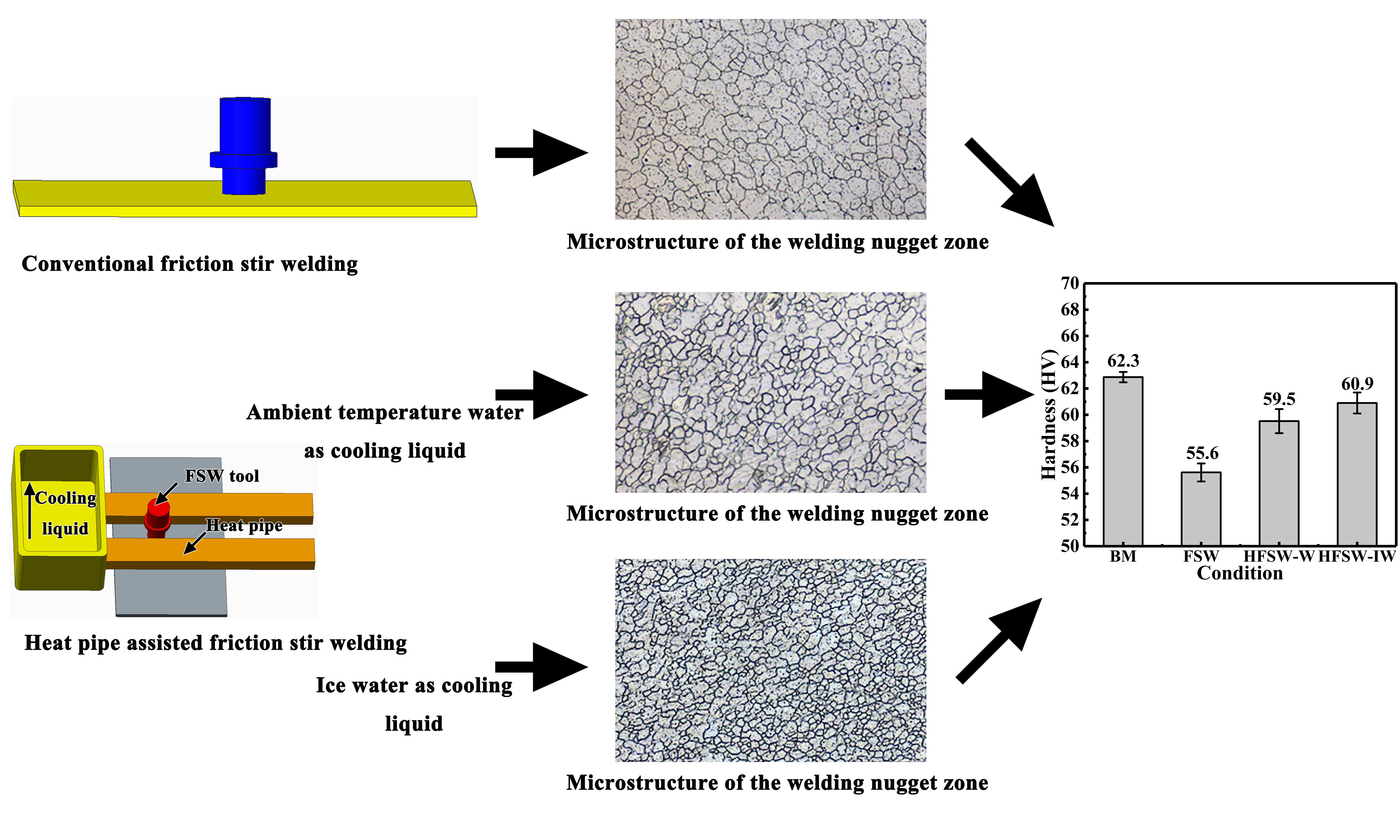
2.2. Heat Pipe-Assisted Friction Stir Welding Setup and Welding Procedure

The friction stir welding facility used in this work was FSW-3LM-002. The FSW tool employed in the current work consisted of a concave shoulder with the diameter of 12 mm and a stirring pin with the shape of the circular truncated cone. The stirring pin has the diameter of 3 mm as its root and the length of 3.8 mm. During the FSW process, the plunge depth of the shoulder was 0.05 mm and the tilt angle of the rotating tool was 2.5°. The main welding parameters, including the welding speed of 50 mm/min and rotation speed of 1500 rpm, were used in the welding processes. In addition, a self-designed heat pipe was applied in the friction stir-welding process (denoted as heat pipe-assisted friction stir welding, HFSW). The heat pipe is made of pure copper and there are wicks made of foamy copper attached closely to the inner wall of the tubes. The relative position of the placed heat pipe is shown in Figure 1. The gap between the two tubes is 24 mm, which is slightly wider than the shoulder of the FSW tool. The rotating direction and welding direction of the rotating tool are also shown in Figure 1. The timing function of the welding machine was used to count the time elapsed since the commencement of the welding process. Ambient temperature water of about 22 °C was applied to the condensing tank at about 77 s, aiming to take away the excessive heat when the stirring tool started to move. Furthermore, for another sample group, ice water was used to enhance the cooling intensity of the heat pipe. The ambient water does not turn into ice water till about 101 s to ensure the relatively sufficient heat input. The time of about 101 s is defined as the time point at which welding process enters the stable period. In order to better distinguish the joints obtained under various welding conditions, the samples used in this work were named as shown in Table 2.

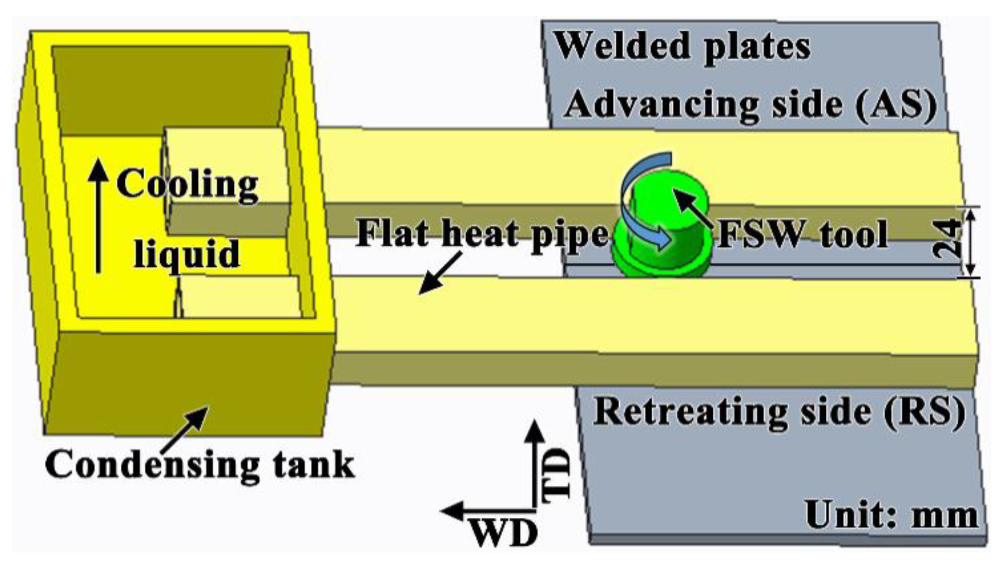
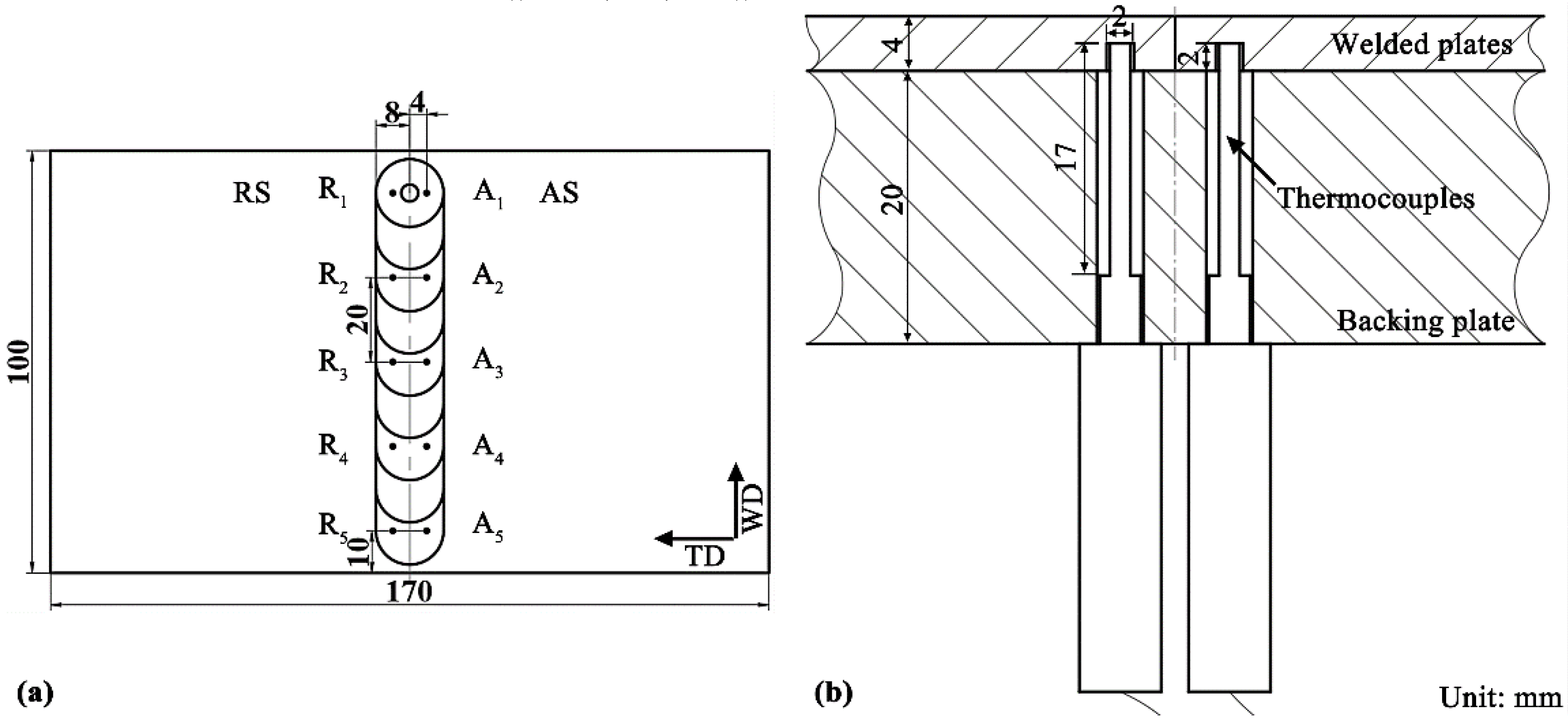
2.3. Measurement of Temperature Field

The temperature field around the FSW tool was measured by K-type thermocouples placed inside the plates along the welding direction. The positions of thermocouples along the welding direction (WD) are displayed in Figure 2a. The thermocouples used in this work have the diameter of 1.5 mm and the length of the measuring parts is 17 mm. There are 5 thermocouples at each side. The measuring parts of the thermocouples are plunged from the back of the welded plates into the hole and contacting with the tips at the location marked as black points in Figure 2a. The depth of each hole is 2 mm. The magnified schema for the fixing directions of the thermocouples and the depth of the hole are shown in Figure 2b. The statistics of the temperature measured by the thermocouples are transmitted and recorded by the paperless recorder DX2048-3-4-3 (Yokogawa Electric Corporation, Guangzhou, China). The thermal response delay of the transmission from the thermocouples is less than 0.5 s and the indication error are no more than 0.3 °C. As shown in Figure 2, these thermocouples were distributed at both the advancing side (AS) and the retreating side (RS), with the interval of 20 mm and the plunging depth of 2 mm.

2.4. Microstructural Characterizations

To analyze the macrostructure and microstructure of the friction stir welded joint, the cross-section of the joint with the distance of 40 mm away from the starting point along the welding direction was examined. This location was at the middle of the weld bead, and the welding process is sufficiently stable here. Macroscopic morphologies of cross section of the samples were photographed by ultra-depth microscope (VHX-900, Keyence Osaka, Japan) and their microstructures were characterized using a light microscope (LM, ZeissAxioskop2-MAT). Before observation, these samples were grinded and carefully polished to a mirror surface finish, and then etched by a mixed reagent consisted of 2 mL HNO3, 2 g H2Cr2O3 and 100 mL H2O for about 7 s.
The grain size in the welded zone was measured by the intercept method according to the ASTM E112-13 standard [36]. The metallographic maps of the weld nugget zone under 200-times magnification in each experimental condition were randomly selected. The number of intersection points between the line and grain boundary was calculated by randomly taking 5 straight lines on the metallographic photographs. The average intercept was calculated by using Equation (1), and the grain size was calculated according to Equation (2).
G = 6.643856 l g l ¯ 3.288
l ¯ = L M · P ,
where G refers to grain size level, and L is the length of the measured line segment (or grid) used, the unit of which is mm, l ¯ is the average interception value of grains (1-times) on sample surface, M is the magnification factor for observation, P is the measuring intersection points on a grid.

2.5. Measurement of Hardness

The microstructure observed on the cross-section changes through the thickness direction of the sample (which is called the normal direction and marked as ND in Figure 3) and transverse direction (which is marked as TD in Figure 3) perpendicular to the welding direction (which is often abbreviated as WD). Four different zones are presented on the cross section of the joint, which can be divided into base metal (BM), heat-affected zone (HAZ), thermal-mechanical affected zone (TMAZ) and weld nugget zone (WNZ) [37]. The etched samples were used for the hardness test. The distribution of testing points for profiling the hardness was marked on a typical pattern of the weld cross-section as shown in Figure 3. In total, the testing points had three rows, and the distance between the top surface and the top row was 1 mm. The distance between the two adjacent rows is 1 mm. There were 31 testing points on each row, and 93 points on total. The interval between the two points of the same row was 0.5 mm. Vickers hardness of the joint was measured by means of a KB30S German automatic hardness tester at a load of 1.96 N with a dwell period of 20 s.

3. Results and Discussion

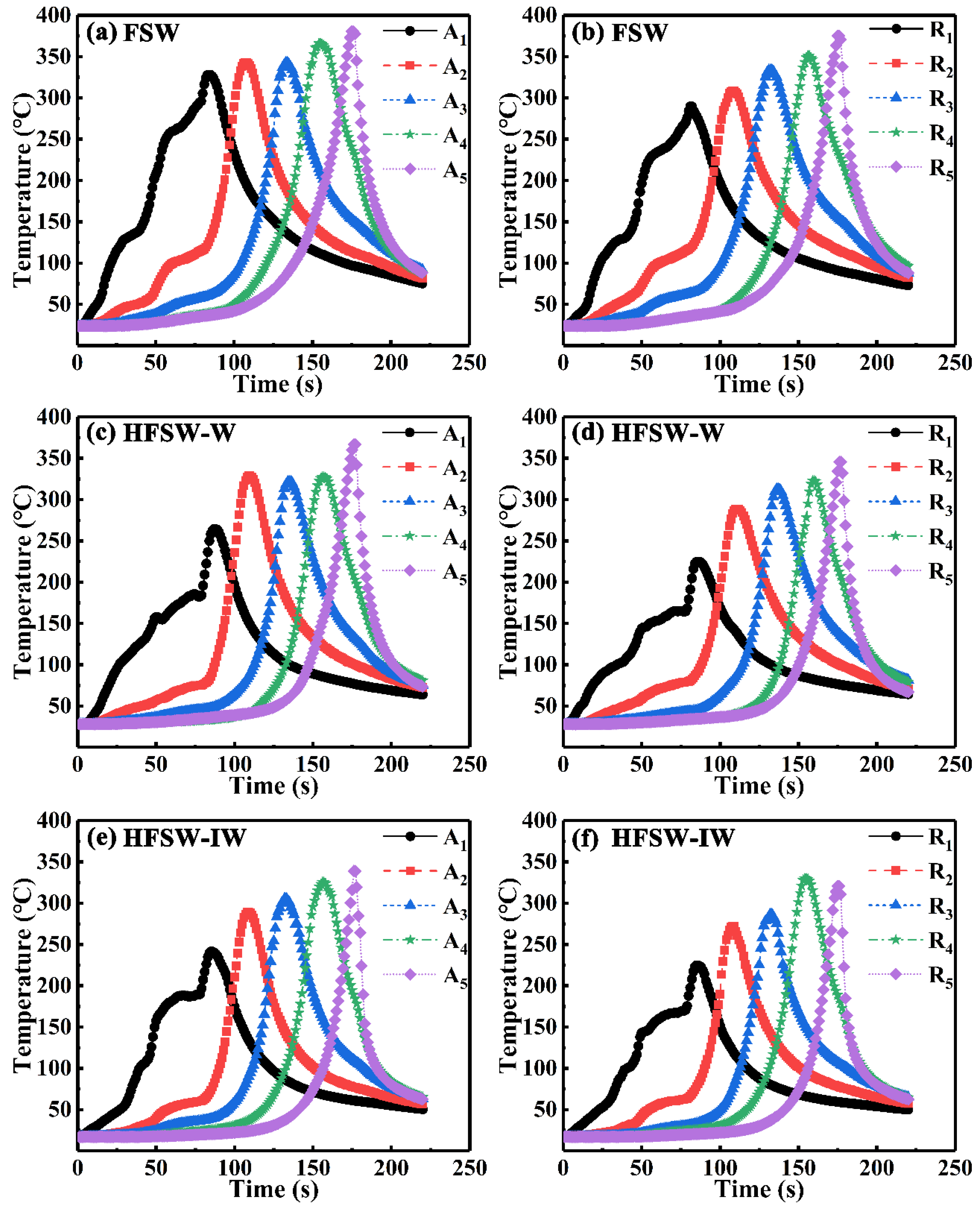
3.1. Thermal Cycle Curve

Figure 4 shows the heat cycle curves of the FSW process both under the conventional condition and heat pipe-assisted condition. Table 3 lists the peak temperatures the feature points under each condition. As shown in Figure 4, the temperatures of all feature points have basically similar trends, which rise to the peak and then drop. According to the data listed in Table 3, the corresponding peak temperature of the feature point at the advancing side (which often has the abbreviation of AS) is higher than that at the retreating side (which often has the abbreviation of RS). Furthermore, the peak temperatures of the feature points at the same side increase along the welding direction, and achieve the highest value at the ending stage (A5 and R5 in each picture shown in Figure 4). As shown in Figure 4a and Table 3, the maximum values of the thermal histories for A1, A3 and A5, which correspond to the starting stage, middle stage and ending stage respectively, are 328 °C, 343 °C and 380 °C in the conventional FSW process. While the peak values measured at R1, R3 and R5 are 289 °C, 333 °C, 375 °C. Such a temperature field is commonly found during the FSW process [23,38,39,40,41]. The distinctions of the peak temperature along the welding direction (WD) are even still presented when the heat pipe is applied in the FSW process, as well as the differences of the temperatures along the transverse direction (the direction perpendicular to the welding direction on the welded plates, which is often abbreviated as TD) [42]. The larger heat loss and unstable generated heat at the beginning of the welding restrict the temperature rising (such as A1 and R1) [43]. This is the main reason for the distinctions of the peak temperatures along WD. In addition, the distinctions of the temperatures along the transverse direction is mainly due to the insufficient material flow around the stirring tool [1]. This phenomenon has also been explained in some previous works [44,45,46,47]. When the FSW tool moves forward, the materials around the tool at the advancing side usually experiences more friction due to their flow directions different from those of the materials farther from the weld bead [45].
When the heat pipe is applied in the FSW process, the excessive heat is taken away due to its excellent conductivity [40,48]. As shown in Figure 4c,d. the peak temperature measured at each feature point decreases due to the application of the heat pipe and the employment of the ambient temperature water as the cooling liquid in the condensing tank. According to the data shown in Table 3, the maximum amplitude reduction of the peak temperature at the starting stage reaches about 64 °C at the advancing side (Figure 4c, A1, 264 °C) and 65 °C at the retreating side (Figure 4d, R1, 225 °C) compared with counterpart welded under the conventional condition. In addition, the peak temperature at the advancing side (Figure 4c, A5, 367 °C) drops about 13 °C and drops about 30 °C (Figure 4d, R5, 346 °C) at the retreating side. As listed in Table 3, when the cooling liquid turns from the ambient temperature water into the ice water, the peak temperature at each measuring point has a further larger decrease (Figure 4e,f). Compared with the conventional FSW condition (Figure 4a, A1, 328 °C and Figure 4b, R1, 289 °C), the peak temperatures of the initial points (Figure 4e, A1, 241 °C and Figure 4f, R1, 225 °C) drop about 87 °C and 64 °C respectively under the HFSW-IW condition. The peak temperature at the advancing side (Figure 4c, A5, 339 °C) drops about 41 °C and about 51 °C at the retreating side (Figure 4d, R5, 321 °C). At the beginning of the FSW process, the heat accumulates gradually. When the generated heat is transferred to the contacting area between the heat pipe and the material surface, the copper tube wall and the working liquid in the wick start to absorb the excessive heat [49]. Similar to the other cooling conditions, the peak temperature is reduced due to the cooling effect of the heat pipe. When the cooling liquid turns into ice water, the cooling intensity generated by the liquid in the condensing tank gets further enhanced. The conductivity is improved due to the increase of the heat transfer coefficient since the temperature of cooling liquid is reduced [50]. The higher heat conductivity makes more heat transfer to the condensing section. As such, more excessive heat is taken away from the plates during the FSW process. Therefore, one can conclude that the application of the heat pipe is capable of reducing the peak temperature under the FSW condition. Moreover, the reduction in peak temperature can be elevated when the cooling intensity is enhanced.
In order to investigate the temperature changes in the middle stage at both the advancing side and the retreating side under three conditions, the temperature curves for the feature points A3 and R3 are shown in Figure 5. As shown in Figure 5a, the peak temperature of A3 at the advancing side is 343 °C, while the peak temperature of R3 at the retreating side is 333 °C (Figure 5b). Compared with the FSW condition, the peak temperatures of A3 (Figure 5c) and R3 (Figure 5d) respectively drop about 22 °C and 20 °C under the HFSW-W condition. Furthermore, compared with the FSW condition, the peak temperatures have a larger reduction (37 °C for A3 and 46 °C for R3) under the HFSW-IW condition (Figure 5e,f). The peak temperatue measured at A3 gets further dropped about 37 °C (Figure 5e) and the peak temperature of R3 drops about 46 °C (Figure 5f). As mentioned above, it is mainly attributed to the cooling effect of the heat pipe on the weld bead. Such results indicate that the cooling intensity of heat pipe is substantially enhanced by ice water.
According to references [51,52], the recrystallization temperature of AZ31 Mg alloy is about 200 °C. The period between the initial temperature above 200 °C and the peak temperature is defined as the temperature-rise stage, and the following period of the black dashed line is defined as the temperature-fall stage. The red dash lines as shown in Figure 5 are marked as the average temperature rising lines. The slope (absolute value) of the average temperature rising line is calculated to investigate the average heating rate under each condition. By comparing the Figure 5a,b, it can be seen that the average heating rate of A3 at the advancing side is higher than that of R3 at at the retreating side under the FSW condition. This is mainly due to the distiction between the peak temperatures at the two sides. As shown in Figure 5a, the average heating rate of the feature point A3 at the advancing side is about 10.36 °C/s and it is about 9.30 °C/s at the retreating side (R3). It takes about 13 s during the temperature-rise stage at the advancing side and about 15 s at the retreating side. Compared with the FSW condition, the average heating rate of A3 (Figure 5c) under the HFSW-W is about 11.92 °C/s. Similar to this, the average heating rate increases about 2.14 °C/s at the retreating side (Figure 5d). The lasting time of the temperature-rise stage decreases about 3 s at the advancing side and about 5 s at the retreating side. When the cooling liquid turns into ice water (under the HFSW-IW condition), the average heating rate at the advancing side is about 9.31 °C/s (Figure 5e) and it is about 8.50 °C/s at the retreating side (Figure 5f). It takes about 11 s for the temperature to rise to the peak temperature at the advancing side and it takes about 8 s at the retreating side. The sustained time of the temperature-rise stage is dependent on both the peak temperature and the average heating rate. The averge heating rate has a large fluctuation under the HFSW-W condition and HFSW-IW condition. But the duration of the temperature-rise stage decreases due to the significant reduction of the peak temperature after the application of the heat pipe during the FSW process.
The black dash lines symmetric to the temparature rising lines are marked as the average temperature falling lines. The slope (absolute value) of the these lines is calculated to investigate the average cooling rate under each condition. As shown in Figure 5a,b, the average cooling rate is also different under the FSW condition due to the distinction between the peak temperatures at the advancing side (A3) and the retreating side (R3). The temperature of A3 under the FSW condition decreases at the average rate of 6.13 °C/s from the peak value to 200 °C. The average cooling rate of the feature point R3 is about 5.66 °C/s (Figure 5b). The temperature-fall stages last about 24 s at both sides. Compared with the FSW condition, the average cooling rate of A3 (Figure 5c) under the HFSW-W is 6.35 °C/s, which is 0.27 °C/s higher than that under the conventional condition. While the average cooling rate of R3 (5.83 °C/s) under the HFSW-W is 0.17 °C/s higher than that of the FSW condition. The sustained time of the temperature-fall stage decreases about 4 s at both sides. When the cooling liquid turns into ice water, the cooling curve becomes steeper. As shown in Figure 5e,f, the average cooling rates of the feature points A3 and R3 are 6.77 °C/s and 8.04 °C/s respectively. The sustained time of the temperature-fall stage decreases about 8 s at the advancing side and about 13 s at the retreating side. As mentioned above, compared with the FSW conditions (Figure 5b), peak temperatures measured at feature points A3 and R3 become lower under the HFSW-W and HFSW-IW conditions. As a matter of common sense, in the absense of additional cooling methods, the average cooling rate generally decreases with the reduction of the initial peak temperature. However, the results shown in Figure 5 show that there are actually increases at both the advancing side and the retreating side after the application of the heat pipe with different cooling liquid in the condensing tank. The highest rising amplitudes of the cooling rate at the advancing side is 0.22 °C/s and 0.17 °C/s at the retreating side. When the cooling liquid turns into ice water, the average cooling rate (absolute value) at the advancing side is 0.64 °C/s higher than that under the FSW condition (Figure 5e). The average cooling rate (absolute value) even increases by 2.38 °C/s at the retreating side (Figure 5f). This phenomenon is also related to the cooling effect of the heat pipe [31,49]. The application of the heat pipe during the FSW process helps take more heat than the conventional cooling condition. For this reason, the average cooling rate measured at each feature point is not obviously reduced and even has an increase. The increasing average cooling rate can make the temperature take less time to decrease to 200 °C. When the cooling liquid turns into ice water, the thermal conductivity of the heat pipe is enhanced and thus improving the cooling effect [50]. Therefore, the average cooling rate has a further rise and, thus, significantly decreasing the duration of the cooling stage. Considering the changes in the sustained time of the heating stage (which is marked as the red dashed line) and cooling stage (which is marked as the black dashed line) comprehensively, the durations above 200 °C can be reduced due to the cooling effect of the heat pipe during the FSW process.

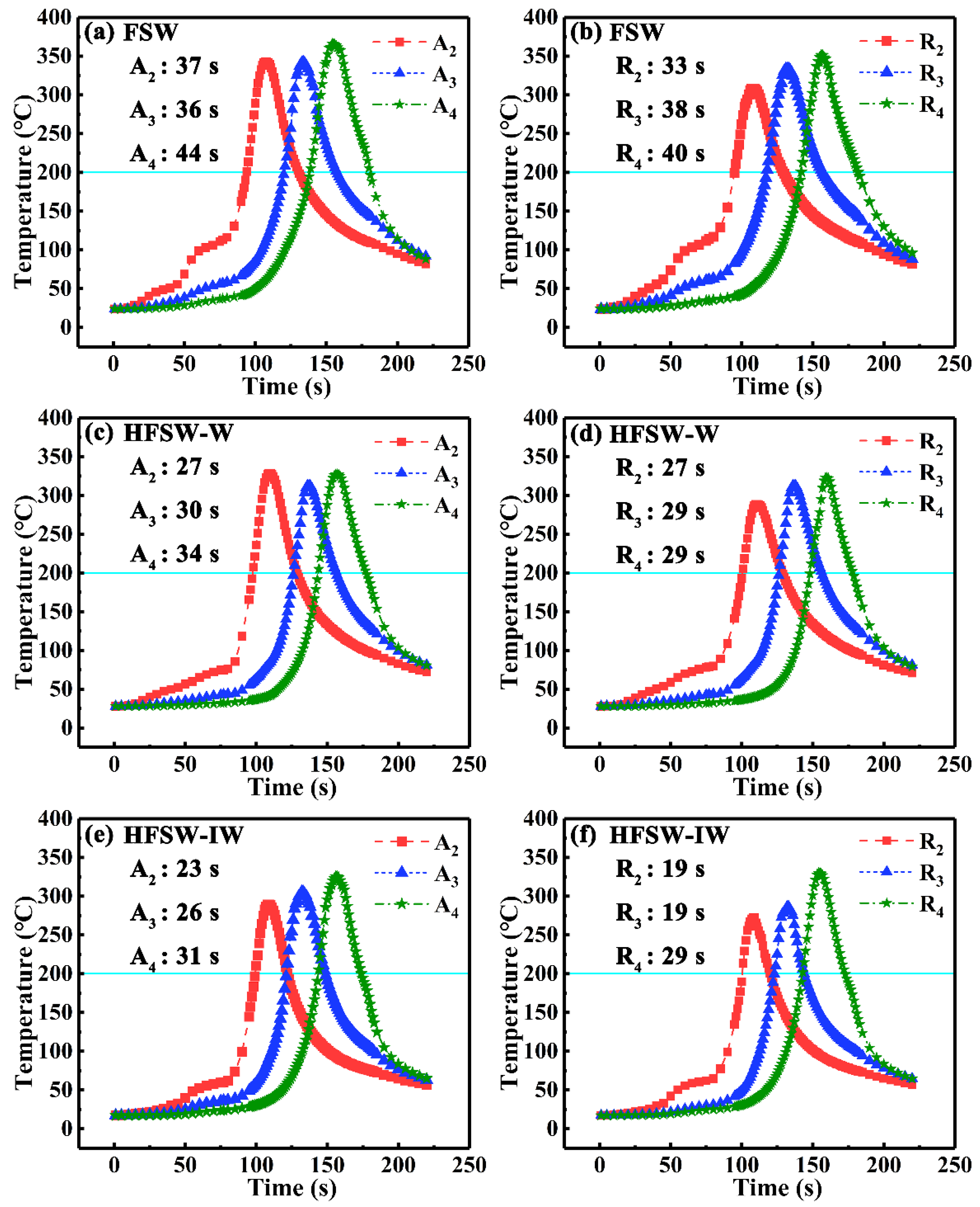
3.2. Duration of the Temperature above 200 °C

During the FSW process, grain refinement, which is capable of improving the mechanical properties of the joints, is mainly attributed to the dynamic recrystallization after the severe plastic deformation [53,54,55]. However, the generated heat during FSW process usually leads the temperature of sample to rise over the recrystallization temperature. In this work, the sustained time above 200 °C is defined as the duration of high temperature. The sustained high temperature promotes the coarsening of grains. Therefore, the duration of high temperature can significantly influence the microstructures and properties of the joints.
As shown in Figure 6, the durations of high temperature are calculated from the thermal cycle curves measured at feature points A2 to A4 and R2 to R4. As seen from Figure 6a,b, the duration of high temperature at the retreating side (RS) is basically lower than the advancing side (AS). The durations of high temperature of the feature points A2 and A3 at the advancing side are both 37 s, and the duration of A4 is 34 s. The durations of high temperature of the feature points R2, R3 and R4 are 33 s, 38 s and 40 s, respectively. Compared with the FSW condition, the durations are reduced when the heat pipe is applied on both sides. The maximum drop of the duration at the advancing side is 10 s (Figure 6c, A2 and A4), and is up to 11 s at the retreating side (Figure 6d, R4) under the HFSW-W condition. The durations of high temperature on both sides of the weld bead further decrease under the HFSW-IW condition (Figure 6e,f). The maximum reduction is about 14 s. These results specify that the decrease of the peak temperature and the slight increase of the cooling rate substantially leads to the reduction in the duration of high temperature of each measured point.

3.3. Macrostructure of the Joint

Figure 7 shows the macrostructures of friction stir the joints under the three conditions. As mentioned above, four distinct regions of weld nugget zone, thermal-mechanical affected zone, heat-affected zone and base material can be observed respectively in the cross sections of joints, which are marked as A, B, C and AD [56]. As seen from Figure 7a, the width of the top part of WNZ is 9.08 mm, while the widths of the middle part and the bottom part are 5.45 mm and 3.82 mm respectively. When the heat pipe is applied in the FSW process, the width of the top part of WNZ is significantly reduced (Figure 7b,c). The width of the top part of WNZ decreases by 2.14 mm under the HFSW-W condition (Figure 7b). The largest reduction in the width of the top part of WNZ takes place under the HFSW-IW condition, which is 3.80 mm (Figure 7c). This is mainly because the superfluous heat on the surface of the sample is dissipated by applying the heat pipe and the material flow is restricted. Moreover, it can be seen that the width of the middle part of the welding zone also experiences a significant decline. The width of the middle part of WNZ is 4.18 mm under the HFSW-W condition (Figure 7b), which is 1.27 mm lower than that under the FSW condition (Figure 7a). When the cooling liquid turns into ice water (HFSW-IW), the decline of the width increases to 1.64 mm. By contrast, the width of the bottom part of WNZ is 3.68 mm under the HFSW-W condition and 3.08 mm under the HFSW-IW condition. Therefore, one can conclude that the effect of heat pipe on the bottom area is much smaller than on other parts.

3.4. Microstructure of the Joint

Figure 8 shows the microstructure of the base material, weld nugget zone, thermal-mechanical affected zone and heat affected zone. As observed in Figure 8a, the microstructure in the base material is bimodal with the presence of few fine equiaxed grains surrounded by elongated coarse grains. Under the FSW condition, the microstructure of WNZ exhibits equiaxed grains due to the severe plastic deformation and the dynamical recrystallization. The average size of the grains in WNZ is about 19.2 μm. Under the HFSW-W condition, some fine grains are presented in the WNZ microstructure under the HFSW-W condition (Figure 8c). The average grain size decreases to 16.8 μm. As shown in Figure 8d, the grains are obviously further refined under the HFSW-IW condition. The average grain size of the WNZ is 12.0 μm. These results indicate that the microstructure of the joint gets significantly refined due to the application of the heat pipe. Such refinement and homogenization become more apparent when ice water is used as the cooling liquid since the generated heat in the FSW process is able to sufficiently dissipate and hence the growth of grains is restrained during processing [30,57]. Therefore, the temperature in WNZ obviously declines under the control of the heat pipe, which eventually leads to the great reduction of the grain size in the material [26,58].

3.5. Hardness of the Joints

Figure 9 shows the hardness profile of the joint under the three conditions. The distributions of the hardness are shown in Figure 9a–d shows the corresponding mean value and the standard deviation of the hardness in WNZ and the mean value of the hardness in base metal (often abbreviated as BM). As shown in Figure 9a, the overall trend of the hardness of the joint presents a W-type pattern [42]. The hardness of the advancing side is slightly lower than the retreating side. The hardness of WNZ under the FSW condition is 55.6 HV. As shown in Figure 9b, when heat pipe is applied to the welding process, the hardness of WNZ gets slightly higher, and the hardness of some locations in WNZ nearly reaches that of base metal that of base metal. Compared with the FSW condition (Figure 9a), the mean value of WNZ under the HFSW-W condition rises up to 59.5 HV (Figure 9d). Figure 9c shows that the hardness of WNZ under the HFSW-IW condition is much higher than that under the FSW condition. As shown in Figure 9d, the average hardness of WNZ is 60.9 HV, which nearly reaches the hardness level of base metal. These results are consistent with the analysis of the microstructure (Figure 8).
It is not difficult to see that the hardness of WNZ is improved by applying the heat pipe compared with the results obtained under the FSW condition. In general, grains in the materials would grow up over the temperature of recrystallization [53,59,60]. The higher the temperature, the larger the grains [61,62]. Therefore, it can be understood that the reduction in the temperature can restrain the growth of the grains in the material during processing or heat treatment [63,64]. In this work, the significant decrease in the peak temperature and the duration of high temperature enable the refinement of the grains. As such, refinement strengthening takes place in WNZ. In the AZ31 alloy, β-Mg17Al12 is the most common second phase presented at the grain boundaries of the matrix phase α-Mg [65]. According to the Mg-Al phase diagram, the transformation of β-Mg17Al12 takes place at the temperature of 437 °C [66]. As a well-known solid-state welding method, the peak temperatures measured during the friction stir welding is relatively lower than this temperature (like the maximum peak temperature of 382 °C recorded in this work). Although the phase transformation may take place in the welded joints, the influence may be not large. Therefore, the influence of grain size is often considered as the main factor to the mechanical properties of the AZ31 alloy welded joints in the literature [67,68]. Therefore, the increase in the mechanical properties (e.g., the hardness) of the welded joints are mainly attributed to the grain refinement in the microstructure. The grains with small size can substantially hinder the movement of the dislocations during the plastic deformation [64,69,70,71,72]. Therefore, the hardness increases eventually. In other word, HFSW-IW is the acceptable cooling condition listed in this work, which can be selected in manufacturing industry.

4. Conclusions

In this work, 4-mm thick AZ31 Mg alloy sheets were welded by friction stir welding (FSW) with/without the assistance of heat pipe. Ambient temperature water and ice water were employed as the cooling liquids applied in the condensing tank. The temperature fields and microstructures of the joints were investigated as well as their hardness. The hardness of the joints was significantly improved after the application of the heat pipe with ice water. Based on the above results, the following conclusions can be drawn:
(1)
The peak temperatures of the feature points at both advancing side (AS, 380 °C) and retreating side (RS, 372 °C) during the conventional friction stir welding process are higher than those (367 °C at AS and 345 °C at RS) under the assistance of the heat pipe with ambient water. After using ice water as cooling liquid, the peak temperatures of the featured points at both AS (339 °C) and RS (321 °C) are further reduced.
(2)
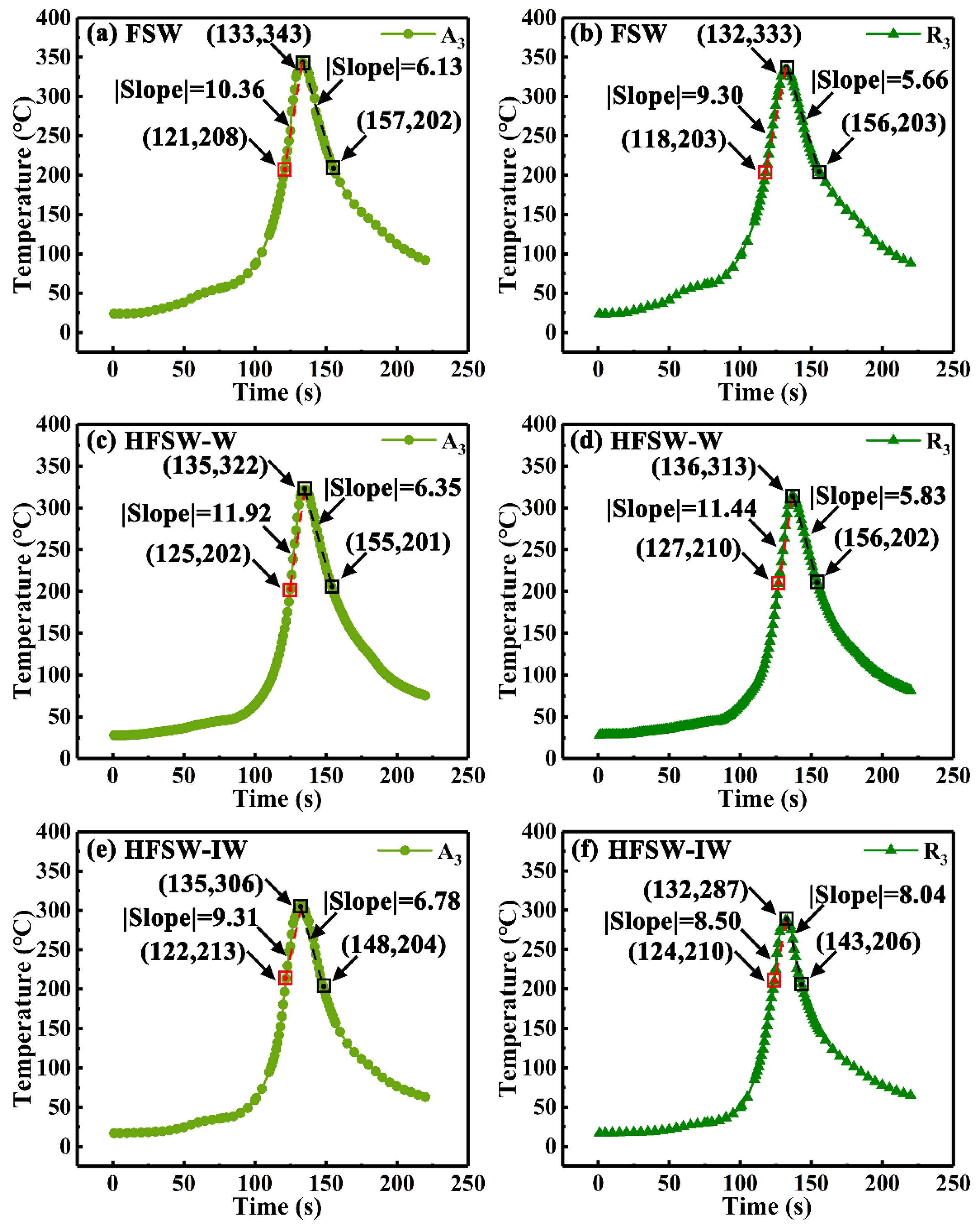
Owing to the application of heat pipe, the durations of high temperature at both AS and RS continuously decrease as the cooling intensity enhances. Correspondingly, the cooling rates of the feature points increase after applying the heat pipe. Especially, the cooling rates of the featured points A3 and R3 respectively decrease by 0.64 °C/s and 2.38 °C/s under the assistance of the heat pipe with ice water compared with the conventional condition.
(3)
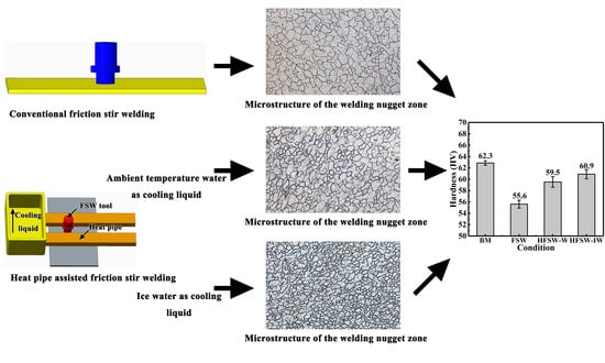
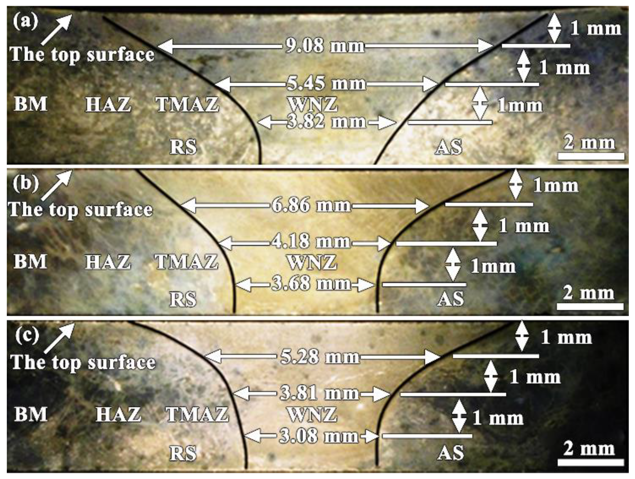
The width of the top area (6.86 mm) and the middle area (4.18 mm) of the weld nugget zone (WNZ) decreases obviously when the heat pipe is applied in the FSW process with the ambient temperature water as cooling liquid, compared with those (9.08 mm of the top area and 5.45 mm of the middle area) under the conventional condition. Moreover, the top area (5.28 mm) and the middle area (3.81 mm) has a further reduction in the width when ice water is employed as cooling liquid. However, the difference in the width of the bottom parts is not obvious due to the relatively low cooling effect of the heat pipe on this area.
(4)
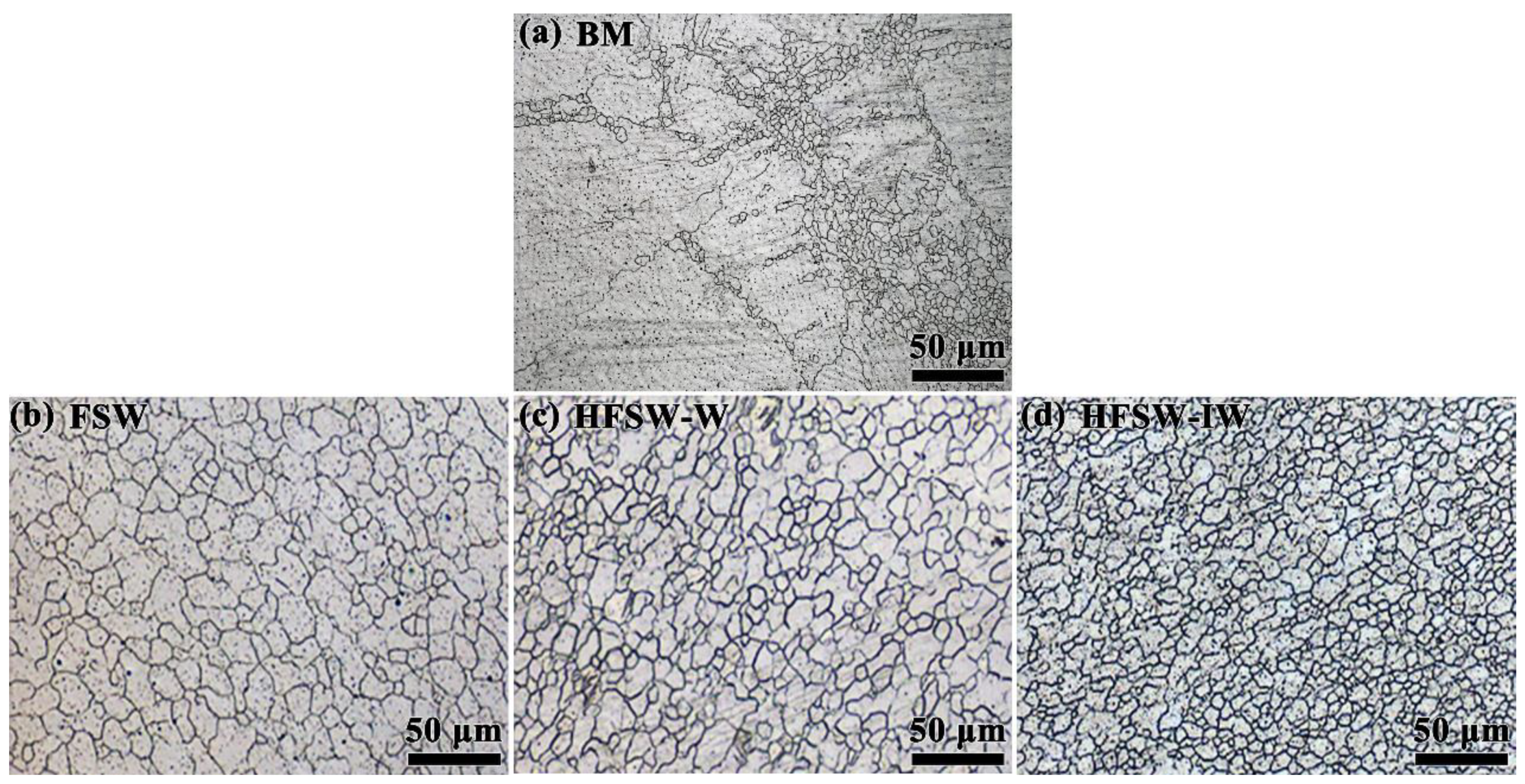
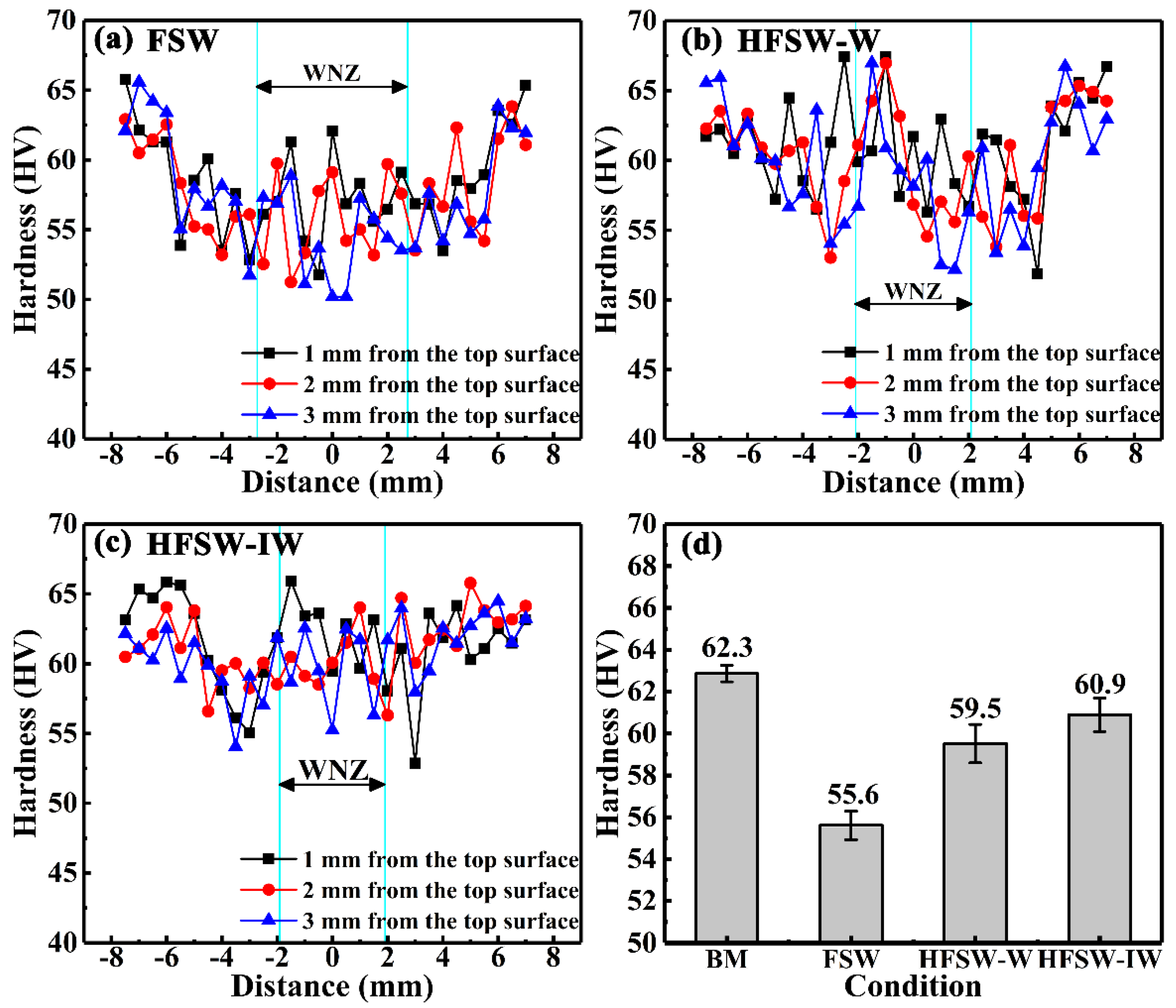
The microstructure of the WNZ becomes refined (average grain size: 16.8 μm) when the heat pipe is applied in the FSW process with the cooling liquid of ambient temperature water compared with that under the conventional condition (average grain size: 19.2 μm). After applying ice water as the cooling liquid, the average grain size in WNZ becomes 12 μm. Hence, the hardness of WNZ rises up to 59.5 HV when heat pipe is applied in the FSW process compared with the conventional condition (55.6 HV) due to the significant decrease in grain size. The larger increase in the hardness (60.9 HV) is presented when ice water is used as cooling liquid.

Author Contributions

Conceptualization, Y.-M.Z.; S.L. and L.-Y.C.; Methodology, Y.-M.Z.; Software, C.Z. and Y.-H.W.; Validation, Y.-M.Z.; Formal Analysis, C.Z. and Y.-M.Z.; Investigation, Y.-M.Z. and Y.-H.W.; Resources, Y.-M.Z.; Data Curation, Y.-M.Z. and Y.-H.W.; Writing—Original Draft Preparation, Y.-M.Z.; Writing—Review and Editing, L.-Y.C. and Y.-M.Z.; Visualization, Y.-M.Z.; Supervision, S.L.; Project Administration, S.L.; Funding Acquisition, L.-Y.C. and S.L.

Funding

The authors would like to acknowledge a financial support provided by National Natural Science Foundation of China (51601075), Open foundation of Guangxi Key Laboratory of Processing for Non-ferrous Metals and Featured Materials, Guangxi University (GXYSOF1801), and Jiangsu Province six talent peaks project (XCL-117) and Postgraduate Research & Practice Innovation Program of Jiangsu Province, Young scholar project in Jiangsu university of science and technology.

Conflicts of Interest

The authors declare no conflict of interest. The funders had no role in the design of the study; in the collection, analyses, or interpretation of data; in the writing of the manuscript; or in the decision to publish the results.

References

  1. Commin, L.; Dumont, M.; Masse, J.E.; Barrallier, L. Friction stir welding of AZ31 magnesium alloy rolled sheets: Influence of processing parameters. Acta Mater. 2009, 57, 326–334. [Google Scholar] [CrossRef]
  2. Eftekhari, M.; Fata, A.; Faraji, G.; Mashhadi, M.M. Hot tensile deformation behavior of Mg-Zn-Al magnesium alloy tubes processed by severe plastic deformation. J. Alloys Compd. 2018, 742, 442–453. [Google Scholar] [CrossRef]
  3. Luo, X.C.; Zhang, D.T.; Zhang, W.W.; Qiu, C.; Chen, D.L. Tensile properties of AZ61 magnesium alloy produced by multi-pass friction stir processing: Effect of sample orientation. Mater. Sci. Eng. A 2018, 725, 398–405. [Google Scholar] [CrossRef]
  4. Wang, Z.; Guan, Y.; Wang, T.; Zhang, Q.; Wei, X.; Fang, X.; Zhu, G.; Gao, S. Microstructure and mechanical properties of AZ31 magnesium alloy sheets processed by constrained groove pressing. Mater. Sci. Eng. A 2019, 745, 450–459. [Google Scholar] [CrossRef]
  5. Wang, Z.-X.; Chen, G.-Q.; Chen, L.-Y.; Xu, L.; Lu, S. Degradation Behavior of Micro-Arc Oxidized ZK60 Magnesium Alloy in a Simulated Body Fluid. Metals 2018, 8, 724. [Google Scholar] [CrossRef]
  6. Čapek, J.; Knapek, M.; Minárik, P.; Dittrich, J.; Máthis, K. Characterization of deformation mechanisms in Mg alloys by advanced acoustic emission methods. Metals 2018, 8, 1–11. [Google Scholar]
  7. Li, Q.; Yan, X.; Luo, L.; Xu, F.; Wu, G.; Liu, C.; Jing, Y.; Liu, Y.; Lu, J. Mechanical properties and corrosion behaviors of AZ31 alloy with dual-phase glass-crystal coating. Mater. Charact. 2019, 154, 200–211. [Google Scholar] [CrossRef]
  8. Subramanian, J.; Loh, Z.; Seetharaman, S.; Hamouda, A.S.; Gupta, M. Microstructure and mechanical properties of Mg-5Nb metal-metal composite reinforced with nano SiC ceramic particles. Metals 2012, 2, 178–194. [Google Scholar] [CrossRef]
  9. Malarvizhi, S.; Balasubramanian, V. Effect of welding processes on AA2219 aluminium alloy joint properties. Trans. Nonferrous Met. Soc. China 2011, 21, 962–973. [Google Scholar] [CrossRef]
  10. He, Z.B.; Peng, Y.Y.; Yin, Z.M.; Lei, X.F. Comparison of FSW and TIG welded joints in Al-Mg-Mn-Sc-Zr alloy plates. Trans. Nonferrous Met. Soc. China 2011, 21, 1685–1691. [Google Scholar] [CrossRef]
  11. Chen, Y.; He, C.; Yang, K.; Zhang, H.; Wang, C.; Wang, Q.; Liu, Y. Effects of microstructural inhomogeneities and micro-defects on tensile and very high cycle fatigue behaviors of the friction stir welded ZK60 magnesium alloy joint. Int. J. Fatigue 2019, 122, 218–227. [Google Scholar] [CrossRef]
  12. Hiscocks, J.; Diak, B.J.; Gerlich, A.P.; Daymond, M.R. Strain localisation and failure of dissimilar magnesium-based alloy friction stir welds. Sci. Technol. Weld. Join. 2018, 23, 628–634. [Google Scholar] [CrossRef]
  13. Mishra, R.S.; De, P.S.; Kumar, N. Friction Stir Welding and Processing; Springer: Berlin, Germany, 2014; ISBN 9783319486048. [Google Scholar]
  14. Shinde, G.; Gajghate, S.; Dabeer, P.S.; Seemikeri, C.Y. Low cost friction stir welding: A review. Mater. Today Proc. 2017, 4, 8901–8910. [Google Scholar] [CrossRef]
  15. Zhang, L.-C.; Chen, L.-Y. A review on biomedical titanium alloys: Recent progress and prospect. Adv. Eng. Mater. 2019, 21, 1801215. [Google Scholar] [CrossRef]
  16. Wang, L.; Xie, L.; Lv, Y.; Zhang, L.C.; Chen, L.; Meng, Q.; Qu, J.; Zhang, D.; Lu, W. Microstructure evolution and superelastic behavior in Ti-35Nb-2Ta-3Zr alloy processed by friction stir processing. Acta Mater. 2017, 131, 499–510. [Google Scholar] [CrossRef]
  17. Wahid, M.A.; Khan, Z.A.; Siddiquee, A.N. Review on underwater friction stir welding: A variant of friction stir welding with great potential of improving joint properties. Trans. Nonferrous Met. Soc. China 2018, 28, 193–219. [Google Scholar] [CrossRef]
  18. Dobriyal, R.P.; Dhindaw, B.K.; Muthukumaran, S.; Mukherjee, S.K. Microstructure and properties of friction stir butt-welded AE42 magnesium alloy. Mater. Sci. Eng. A 2008, 477, 243–249. [Google Scholar] [CrossRef]
  19. Pan, F.; Xu, A.; Deng, D.; Ye, J.; Jiang, X.; Tang, A.; Ran, Y. Effects of friction stir welding on microstructure and mechanical properties of magnesium alloy Mg-5Al-3Sn. Mater. Des. 2016, 110, 266–274. [Google Scholar] [CrossRef]
  20. Silva-Magalhães, A.; De Backer, J.; Martin, J.; Bolmsjö, G. In-situ temperature measurement in friction stir welding of thick section aluminium alloys. J. Manuf. Process. 2019, 39, 12–17. [Google Scholar] [CrossRef]
  21. Swarnkar, A.; Kumar, R.; Suri, A.; Sahay, A. A review on Friction Stir Welding: An environment friendly welding technique. In Proceedings of the 2016 IEEE Region 10 Humanitarian Technology Conference (R10-HTC), Agra, India, 21–23 December 2016; pp. 1–4. [Google Scholar]
  22. Darras, B.; Kishta, E. Submerged friction stir processing of AZ31 Magnesium alloy. Mater. Des. 2013, 47, 133–137. [Google Scholar] [CrossRef]
  23. Lu, S.; Chen, J.; Jia, X.D.; Wang, Z.X.; Gong, J.J. Thermal cycle characteristics of AM 50 magnesium alloy welded by FSW. Key Eng. Mater. 2009, 419–420, 533–536. [Google Scholar] [CrossRef]
  24. Mehta, K.P.; Carlone, P.; Astarita, A.; Scherillo, F.; Rubino, F.; Vora, P. Conventional and cooling assisted friction stir welding of AA6061 and AZ31B alloys. Mater. Sci. Eng. A 2019, 759, 252–261. [Google Scholar] [CrossRef]
  25. Liu, H.J.; Zhang, H.J.; Huang, Y.X.; Yu, L. Mechanical properties of underwater friction stir welded 2219 aluminum alloy. Trans. Nonferrous Met. Soc. China 2010, 20, 1387–1391. [Google Scholar] [CrossRef]
  26. Wang, B.B.; Chen, F.F.; Liu, F.; Wang, W.G.; Xue, P.; Ma, Z.Y. Enhanced mechanical properties of friction stir welded 5083Al-H19 joints with additional water cooling. J. Mater. Sci. Technol. 2017, 33, 1009–1014. [Google Scholar] [CrossRef]
  27. Ma, Z.; Wang, Y.; Ji, S.; Xiong, L. Fatigue properties of Ti-6Al-4V alloy friction stir welding joint obtained under rapid cooling condition. J. Manuf. Process. 2018, 36, 238–247. [Google Scholar] [CrossRef]
  28. Xu, N.; Ueji, R.; Morisada, Y.; Fujii, H. Modification of mechanical properties of friction stir welded Cu joint by additional liquid CO2 cooling. Mater. Des. 2014, 56, 20–25. [Google Scholar] [CrossRef]
  29. Ramaiyan, S.; Chandran, R.; Santhanam, S.K.V. Effect of cooling conditions on mechanical and microstructural behaviours of friction stir processed AZ31B Mg alloy. Mod. Mech. Eng. 2017, 7, 144–160. [Google Scholar] [CrossRef]
  30. Lu, S.; Zhang, W.; Chen, S.J.; Yao, S.G. Effect of flat heat pipe on the properties of the FSW joint. Mater. Sci. Forum 2016, 850, 693–699. [Google Scholar] [CrossRef]
  31. Mustaffar, A.; Phan, A.N.; Reay, D.; Boodhoo, K. Concentric annular heat pipe characterisation analysis for a drying application. Appl. Therm. Eng. 2019, 149, 275–286. [Google Scholar] [CrossRef]
  32. Grover, G.M.; Cotter, T.P.; Erickson, G.F. Structures of very high thermal conductance. J. Appl. Phys. 1964, 35, 1990–1991. [Google Scholar] [CrossRef]
  33. Han, X.; Wang, X.; Zheng, H.; Xu, X.; Chen, G. Review of the development of pulsating heat pipe for heat dissipation. Renew. Sustain. Energy Rev. 2016, 59, 692–709. [Google Scholar] [CrossRef]
  34. Mahdavi, M.; Tiari, S.; De Schampheleire, S.; Qiu, S. Experimental study of the thermal characteristics of a heat pipe. Exp. Therm. Fluid Sci. 2018, 93, 292–304. [Google Scholar] [CrossRef]
  35. Xiahou, G.; Zhang, J.; Ma, R.; Liu, Y. Novel heat pipe radiator for vertical CPU cooling and its experimental study. Int. J. Heat Mass Transf. 2019, 130, 912–922. [Google Scholar] [CrossRef]
  36. Gajalakshmi, K.; Palanivel, S.; Nalini, N.J.; Saravanan, S.; Raghukandan, K. Grain size measurement in optical microstructure using support vector regression. Optik (Stuttg) 2017, 138, 320–327. [Google Scholar]
  37. Lu, S.; Xiao, S.Y.; Qi, F.; Chen, J. Microstructure and mechanical property along 3D directions of AZ31 magnesium joint welded by FSW. Adv. Mater. Res. 2012, 567, 187–191. [Google Scholar] [CrossRef]
  38. Albakri, A.N.; Mansoor, B.; Nassar, H.; Khraisheh, M.K. Thermo-mechanical and metallurgical aspects in friction stir processing of AZ31 Mg alloy—A numerical and experimental investigation. J. Mater. Process. Technol. 2013, 213, 279–290. [Google Scholar] [CrossRef]
  39. Milagre, M.X.; Mogili, N.V.; Donatus, U.; Giorjão, R.A.R.; Terada, M.; Araujo, J.V.S.; Machado, C.S.C.; Costa, I. On the microstructure characterization of the AA2098-T351 alloy welded by FSW. Mater. Charact. 2018, 140, 233–246. [Google Scholar] [CrossRef]
  40. Huang, Q.; Li, X.; Zhang, G.; Zhang, J.; He, F.; Li, Y. Experimental investigation of the thermal performance of heat pipe assisted phase change material for battery thermal management system. Appl. Therm. Eng. 2018, 141, 1092–1100. [Google Scholar] [CrossRef]
  41. Shah, P.H.; Badheka, V. An experimental investigation of temperature distribution and joint properties of Al 7075 T651 friction stir welded aluminium alloys. Procedia Technol. 2016, 23, 543–550. [Google Scholar] [CrossRef] [Green Version]
  42. Serindag, H.T.; Kiral, B.G. Friction stir welding of AZ31 magnesium alloys—A numerical and experimental study. Lat. Am. J. Solids Struct. 2017, 14, 113–130. [Google Scholar] [CrossRef] [Green Version]
  43. Lu, S.; Yang, D.L.; Xiao, S.Y.; Chen, S.J. Three-dimensional investigation on temperature distribution and mechanical properties of AZ31Mg alloy joint welded by FSW. In Proceedings of the 1st International Joint Symposium on Joining and Welding, Osaka, Japan, 6–8 November 2013; pp. 67–72. [Google Scholar]
  44. Zhang, S.; Shi, Q.; Liu, Q.; Xie, R.; Zhang, G.; Chen, G. Effects of tool tilt angle on the in-process heat transfer and mass transfer during friction stir welding. Int. J. Heat Mass Transf. 2018, 125, 32–42. [Google Scholar] [CrossRef]
  45. Chen, G.Q.; Shi, Q.Y.; Li, Y.J.; Sun, Y.J.; Dai, Q.L.; Jia, J.Y.; Zhu, Y.C.; Wu, J.J. Computational fluid dynamics studies on heat generation during friction stir welding of aluminum alloy. Comput. Mater. Sci. 2013, 79, 540–546. [Google Scholar] [CrossRef]
  46. Chen, G.; Wang, G.; Shi, Q.; Zhao, Y.; Hao, Y.; Zhang, S. Three-dimensional thermal-mechanical analysis of retractable pin tool friction stir welding process. J. Manuf. Process. 2019, 41, 1–9. [Google Scholar] [CrossRef]
  47. Long, L.; Chen, G.; Zhang, S.; Liu, T.; Shi, Q. Finite-element analysis of the tool tilt angle effect on the formation of friction stir welds. J. Manuf. Process. 2017, 30, 562–569. [Google Scholar] [CrossRef]
  48. Xin, F.; Ma, T.; Wang, Q. Theoretical analysis of flat heat pipe with graded-porosity wick design. Energy Procedia 2017, 142, 3932–3938. [Google Scholar] [CrossRef]
  49. Pandiyaraj, P.; Gnanavelbabu, A.; Saravanan, P. Experimental analysis on thermal performance of fabricated flat plate heat pipe using titanium dioxide nanofluid. Mater. Today Proc. 2018, 5, 8414–8423. [Google Scholar] [CrossRef]
  50. Nguyen, T.T.T.; Kundan, A.; Wayner, P.C.; Plawsky, J.L.; Chao, D.F.; Sicker, R.J. Effects of cooling temperature on heat pipe evaporator performance using an ideal fluid mixture in microgravity. Exp. Therm. Fluid Sci. 2016, 75, 108–117. [Google Scholar] [CrossRef]
  51. Lee, J.H.; Lee, J.U.; Kim, S.H.; Song, S.W.; Lee, C.S.; Park, S.H. Dynamic recrystallization behavior and microstructural evolution of Mg alloy AZ31 through high-speed rolling. J. Mater. Sci. Technol. 2018, 34, 1747–1755. [Google Scholar] [CrossRef]
  52. Yang, X.; Ji, Z.; Miura, H.; Sakai, T. Dynamic recrystallization and texture development during hot deformation of magnesium alloy AZ31. Trans. Nonferrous Met. Soc. Chin. 2009, 19, 55–60. [Google Scholar] [CrossRef]
  53. Mironov, S.; Onuma, T.; Sato, Y.S.; Kokawa, H. Microstructure evolution during friction-stir welding of AZ31 magnesium alloy. Acta Mater. 2015, 100, 301–312. [Google Scholar] [CrossRef]
  54. Chen, L.; Li, J.; Zhang, Y.; Lu, W.; Zhang, L.-C.; Wang, L.; Zhang, D. Effect of low-temperature pre-deformation on precipitation behavior and microstructure of a Zr-Sn-Nb-Fe-Cu-O alloy during fabrication. J. Nucl. Sci. Technol. 2016, 53, 496–507. [Google Scholar] [CrossRef]
  55. Wang, L.; Qu, J.; Chen, L.; Meng, Q.; Zhang, L.-C.; Qin, J.; Zhang, D.; Lu, W. Investigation of deformation mechanisms in β-Type Ti-35Nb-2Ta-3Zr alloy via FSP leading to surface strengthening. Metall. Mater. Trans. A 2015, 46, 4813–4818. [Google Scholar] [CrossRef]
  56. Afrin, N.; Chen, D.L.; Cao, X.; Jahazi, M. Microstructure and tensile properties of friction stir welded AZ31B magnesium alloy. Mater. Sci. Eng. A 2008, 472, 179–186. [Google Scholar] [CrossRef]
  57. Chen, L.-Y.; Sang, P.; Zhang, L.; Song, D.; Chu, Y.-Q.; Chai, L.; Zhang, L.-C. Homogenization and growth behavior of second-phase particles in a deformed Zr–Sn-Nb-Fe-Cu-Si-O alloy. Metals 2018, 8, 759. [Google Scholar] [CrossRef] [Green Version]
  58. Zhang, L.C.; Xu, J.; Ma, E. Mechanically Alloyed Amorphous Ti50(Cu0.45Ni0.55)44–xAlxSi4B2 Alloys with Supercooled Liquid Region. J. Mater. Res. 2002, 17, 1743–1749. [Google Scholar] [CrossRef] [Green Version]
  59. Chen, L.Y.; Xu, T.; Lu, S.; Wang, Z.X.; Chen, S.; Zhang, L.C. Improved hardness and wear resistance of plasma sprayed nanostructured NiCrBSi coating via short-time heat treatment. Surf. Coatings Technol. 2018, 350, 436–444. [Google Scholar] [CrossRef]
  60. Zhang, L.C.; Shen, Z.Q.; Xu, J. Mechanically milling-induced amorphization in Sn-containing Ti-based multicomponent alloy systems. Mater. Sci. Eng. A 2005, 394, 204–209. [Google Scholar] [CrossRef]
  61. Yang, Z.N.; Wang, X.B.; Liu, F.; Zhang, F.C.; Chai, L.J.; Qiu, R.S.; Chen, L.Y. Effect of intercritical annealing temperature on microstructure and mechanical properties of duplex Zr-2.5Nb alloy. J. Alloys Compd. 2019, 776, 242–249. [Google Scholar] [CrossRef]
  62. Zhang, M.; Li, Y.N.; Zhang, F.C.; Wang, X.B.; Chen, L.Y.; Yang, Z.N. Effect of annealing treatment on the microstructure and mechanical properties of a duplex Zr-2.5 Nb alloy. Mater. Sci. Eng. A 2017, 706, 236–241. [Google Scholar] [CrossRef]
  63. Chen, L.; Li, J.; Zhang, Y.; Zhang, L.C.; Lu, W.; Wang, L.; Zhang, L.; Zhang, D. Zr-Sn-Nb-Fe-Si-O alloy for fuel cladding candidate: Processing, microstructure, corrosion resistance and tensile behavior. Corros. Sci. 2015, 100, 332–340. [Google Scholar] [CrossRef]
  64. Chen, L.; Zeng, Q.; Li, J.; Lu, J.; Zhang, Y.; Zhang, L.C.; Qin, X.; Lu, W.; Zhang, L.; Wang, L.; et al. Effect of microstructure on corrosion behavior of a Zr-Sn-Nb-Fe-Cu-O alloy. Mater. Des. 2016, 92, 888–896. [Google Scholar] [CrossRef]
  65. Kumar, P.P.; Bharat, A.R.; Sai, B.S.; Sarath, R.J.P.; Akhil, P. ScienceDirect Role of microstructure and secondary phase on corrosion behavior of heat treated AZ series magnesium alloys. Mater. Today Proc. 2019, 18, 175–181. [Google Scholar] [CrossRef]
  66. Xiong, X.; Yang, Y.; Li, J.; Li, M.; Peng, J.; Wen, C. Research on the microstructure and properties of a multi-pass friction stir processed 6061Al coating for AZ31 Mg alloy. J. Magnes. Alloy. 2019, 8, 552–562. [Google Scholar] [CrossRef]
  67. Zhao, G.; Fan, J.; Zhang, H.; Zhang, Q.; Yang, J.; Dong, H.; Xu, B. Exceptional mechanical properties of ultra-fine grain AZ31 alloy by the combined processing of ECAP, rolling and EPT. Mater. Sci. Eng. A 2018, 731, 54–60. [Google Scholar] [CrossRef]
  68. Chen, S.; Zhang, H.; Jiang, X.; Yuan, T.; Han, Y.; Li, X. Mechanical properties of electric assisted friction stir welded 2219 aluminum alloy. J. Manuf. Process. 2019, 44, 197–206. [Google Scholar] [CrossRef]
  69. Chen, L.Y.; Shen, P.; Zhang, L.; Lu, S.; Chai, L.; Yang, Z.; Zhang, L.C. Corrosion behavior of non-equilibrium Zr-Sn-Nb-Fe-Cu-O alloys in high-temperature 0.01 M LiOH aqueous solution and degradation of the surface oxide films. Corros. Sci. 2018, 136, 221–230. [Google Scholar] [CrossRef]
  70. Chai, L.; Chen, K.; Zhi, Y.; Murty, K.L.; Chen, L.Y.; Yang, Z. Nanotwins induced by pulsed laser and their hardening effect in a Zr alloy. J. Alloys Compd. 2018, 748, 163–170. [Google Scholar] [CrossRef]
  71. Calin, M.; Zhang, L.C.; Eckert, J. Tailoring of microstructure and mechanical properties of a Ti-based bulk metallic glass-forming alloy. Scr. Mater. 2007, 57, 1101–1104. [Google Scholar] [CrossRef]
  72. Su, L.H.; Lu, C.; He, L.Z.; Zhang, L.C.; Guagliardo, P.; Tieu, A.K.; Samarin, S.N.; Williams, J.F.; Li, H.J. Study of vacancy-type defects by positron annihilation in ultrafine-grained aluminum severely deformed at room and cryogenic temperatures. Acta Mater. 2012, 60, 4218–4228. [Google Scholar] [CrossRef] [Green Version]
Figure 1. Schematic illustration of the setup of heat pipe-assisted friction stir welding (HFSW). The welding direction is marked as WD and the direction perpendicular to it is marked as TD.
Metals 09 01227 g001
Figure 2. The schema of the thermocouples fixed in the welded plates: (a) The distribution of thermocouples along the welding direction and the transverse direction (unit: mm). In this map, the black points indicate the K-type thermocouples (total of 5 thermocouples at each side). The black points marked as A1 to A5 are the feature points distributed at the advancing side (AS), and R1 to R5 are the feature points at the retreating side (RS). The welding direction is marked as WD and the direction perpendicular to it on the welded plates is marked as TD. (b) is the magnified schema for the fixing directions of the thermocouples and the depth of the hole.
Metals 09 01227 g002
Figure 3. Schematic map of the measurement of Vickers micro-hardness. The distance between the top row and the top surface is 1 mm, and the distance between the adjacent rows is 1 mm. The interval between two points is 0.5 mm. Transverse direction perpendicular to the welding direction is marked as TD. The direction along the thickness of the joint is called the nominal direction and marked as ND.
Metals 09 01227 g003
Figure 4. The heat cycling curves measured at: (a) the advancing side (A1 to A5) under the friction stir welding (FSW) condition; (b) the retreating side (R1 to R5) under the FSW condition; (c) the advancing side (A1 to A5) under the HFSW-W condition; (d) the retreating side (R1 to R5) under the HFSW condition; (e) the advancing side (A1 to A5) under the HFSW-IW condition; (f) the retreating side (R1 to R5) under the HFSW-IW condition. FSW means the conventional friction stir welding; HFSW-W indicates the heat pipe assisted friction stir welding with ambient temperature water as the cooling liquid; HFSW-IW is the heat pipe assisted friction stir welding employing ice water as the cooling liquid.
Metals 09 01227 g004
Figure 5. The thermal cycle curves of: (a) feature point A3 under the FSW condition; (b) feature point R3 under the FSW condition; (c) feature point A3 under the HFSW-W condition; (d) feature point R3 under the HFSW-W condition; (e) feature point A3 under the HFSW-IW condition; (f) feature point R3 under the HFSW-IW condition.
Metals 09 01227 g005
Figure 6. The durations of high temperature calculated from the thermal curve of: (a) feature points A2 to A4 at the advancing side under the FSW condition; (b) feature points R2 to R4 at the retreating side under the FSW condition; (c) feature points A2 to A4 at the advancing side under the HFSW-W condition; (d) feature points R2 to R4 at the retreating side under the HFSW-W condition; (e) feature points A2 to A4 at the advancing side under the HFSW-IW condition; (f) feature points R2 to R4 at the retreating side under the HFSW-IW condition.
Metals 09 01227 g006
Figure 7. The macrostructures of the joints under: (a) the FSW condition; (b) the HFSW-W condition; (c) the HFSW-IW condition.
Metals 09 01227 g007
Figure 8. The microstructure of: (a) base material (BM); (b) the weld nugget zone (WNZ) under the FSW condition; (c) the weld nugget zone under the HFSW-W condition; (d) the weld nugget zone under the HFSW-IW condition; FSW means the conventional friction stir welding; HFSW-W indicates the heat pipe assisted friction stir welding with ambient temperature water as the cooling liquid; HFSW-IW is the heat pipe-assisted friction stir welding employing ice water as the cooling liquid.
Metals 09 01227 g008
Figure 9. The hardness of the joints under: (a) the FSW condition, (b) the HFSW-W condition and (c) the HFSW-IW condition. (d) is the average value of hardness measured in WNZ under each condition and the mean value of base metal (abbreviated as BM in figure (d)).
Metals 09 01227 g009
Table 1. Chemical compositions (in wt.%) of the base metals.
AlZnSiFeCuMnMg
3.621.240.050.010.010.02Bal
Table 2. Denotation of samples under different welding conditions.
Serial NumberNameWelding Condition
1FSW Joints obtained under the conventional friction stir welding condition.
2HFSW-W Joints obtained when heat pipe is applied into the welding process and the ambient temperature water is employed as cooling liquid in the condensing tank since the time reached 77 s.
3HFSW-IW Joints obtained when heat pipe is applied into the welding process and the ambient temperature water is turned into ice water since the time reached 101 s.
Table 3. Peak temperature (°C) of each measuring points.
SampleFeature Point (AS/RS)
A1/R1A2/R2A3/R3A4/R4A5/R5
FSW328/289342/308343/333366/351380/375
HFSW-W264/225329/288322/313327/323367/346
HFSW-IW241/225289/272306/287326/330339/321

