Article

Evaluation of Support Structure Removability for Additively Manufactured Ti6Al4V Overhangs via Electron Beam Melting

by
Wadea Ameen
1,2,*,
Muneer Khan Mohammed
2 and
Abdulrahman Al-Ahmari
1,2
1
Industrial Engineering Department, King Saud University, Riyadh P.O. Box 800-Riyadh 11421, Saudi Arabia
2
Raytheon Chair for Systems Engineering (RCSE Chair), Advanced Manufacturing Institute, King Saud University, Riyadh P.O. Box 800-Riyadh 11421, Saudi Arabia
*
Author to whom correspondence should be addressed.
Metals 2019, 9(11), 1211; https://doi.org/10.3390/met9111211
Submission received: 22 October 2019 / Revised: 5 November 2019 / Accepted: 9 November 2019 / Published: 11 November 2019
(This article belongs to the Special Issue Metal Additive Manufacturing – State of the Art 2020)

Abstract

:
The addition of support structures is essential for the successful fabrication of overhang structures through additive manufacturing (AM). The support structures protect the overhang portion from distortions. They are fabricated with the functional parts and are removed later after the fabrication of the AM part. While structures bearing insufficient support result in defective overhangs, structures with excessive support result in higher material consumption, time and higher post-processing costs. The objective of this study is to investigate the effects of design and process parameters of support structures on support removability during the electron beam melting (EBM)-based additive manufacturing of the Ti6Al4V overhang part. The support design parameters include tooth parameters, no support offset, fragmentation parameters and perforation parameters. The EBM process parameters consist of beam current, beam scan speed and beam focus offset. The results show that both support design and process parameters have a significant effect on support removability. In addition, with the appropriate selection of design and process parameters, it is possible to significantly reduce the support removal time and protect the surface quality of the part.

1. Introduction and Literature Review

Additive manufacturing (AM) is a manufacturing technique used to fabricate three-dimensional parts in a layer-by-layer manner directly from a computer-aided design (CAD) model. In powder-bed-fusion (PBF) processes, such as electron beam melting (EBM), and in selective laser sintering and melting, a thin powder layer is selectively melted using an electron or laser beam [1,2]. Once the powder layer is molten, a new powder layer is spread and melted based upon the CAD data, the steps are repeated until the full component is fabricated. Although PBF technology can fabricate complex geometries, it has some limitations in the fabrication of structures with overhang geometries. The fabrication of structures with overhang geometries that do not contain support structures results in warpage deformation due to the thermal gradient and residual stress.
Support structures are essential in the manufacturing of defect-free overhang structures through the PBF process [3]. By facilitating the removal of heat from the structure, support structures prevent part curling, distortion, sagging, cracks, shrinkage, and/or other deformations that result from thermal stresses. They also serve to hold the fabricated part in the construction platform during the manufacturing process [4]. Current support generation methods usually involve the use of certain types of structures to cover the overhang space. These methods may result in overestimation of the support volume or the placement of a large number of supports, which may be unnecessary and increase the post-processing time [5]. Support structures have many design rules that are to be incorporated by the designers. For example, the support structures should be designed to engage in minimal contact with the overhang surface parts [6]. The design of the support structure must also consider the post-processing costs. For instance, minimising the number of supports, which leads to a minimal number of marks on the surface and reduces the amount of part clean-up and post-processing [7]. Support structures are the non-functional part of the structure and are removed after the construction process. Optimisation of the support structure is an important consideration for the successful fabrication of parts. Accurate selection of support structure design is critical, as it affects the production cost, time and quality of construction. For example, applying a large contact area support to the overhang part would result in increased difficulty in support removal, and it might damage the part surface during removal [8,9]. The support structures are used to build the overhanging geometries and are later removed by breaking them away. Often, commercial software like Magics (Materialise, Leuven, Belgium) is used to automatically generate support structures. After the parts are fabricated using AM technology (EBM), the excess powder and support structures are removed. In PBF, the support structures are mechanically removed by the application of force or cutting (often manually) [10]. In some cases, the inability to remove the support structures leads to the inability to manufacture the desired structures. Various methods are used to remove metal support structures, depending on the material and geometry. Wire electrical discharge machining, saws [10,11], Dremel handheld power tools [12] and pliers [13] are popular methods and tools for removing the support structures from PBF parts [14]. Sandpaper is a quick tool that is used to remove the witness marks leftover by the supports on the bottom surface.
For metal supports, a wire EDM machine, milling equipment, and bandsaw may be required to remove the part support from the baseplate and then remove the supports from the part [7]. Most of the AM cost models consider support structures as main parts and as a factor in the estimate of the total cost. Furthermore, some cost models consider the density of the support structure to estimate the cost of AM [15,16]. Calignano et al. investigated the effect of block support structures fabricated by selective laser melting of aluminium and titanium alloys. The results show that the removal of the support structures from the titanium samples is an easier task as compared to the aluminium samples. In addition, the support design has an effect on the removability of the applied support structures [17]. Kuo et al. used topology optimisation to design an easily removable support structure that minimises support material and fabrication time, and results in the fewest artefacts on the surface of the specimen. A cost-based formulation, comprising a simple and straightforward method, is employed to find a compromise between the cost and surface profile error induced by specimen weight [18]. To select the type of support structure design for optimal support removability and the surface quality of the parts, Järvinen et al. compared the properties of two types of support structures (web and tube) during the evaluation of removability. The results showed that the web supports provided superior removability as compared to the tube supports [19]. All block support structure parameters (tooth, no support offset parameters, fragmentation, and perforation parameters) are shown in Figure 1.
In the EBM process, parameters such as beam current (I), beam scanning speed (V), line offset (LO) and beam focus offset (FO) are the most relevant process parameters [20]. Line offset refers to the distance between two hatch lines, and focus offset is the offset of the focal plane from its zero position. Increased line offset results in lower energy densities, which forms voids in Ti-6Al-4V specimens. An increase in the focus offset increases the beam diameter and reduces the energy density, which in turn, results in an increase in the porosity [21]. From the above parameters, the energy density (J/mm2) can be calculated as follows [22]:
Q   =   Π   ×   V a c c   ×   I s c a n   ×   γ a b s 4   ×   D b e a m   ×   V s c a n
where Q is energy input/mm2 (J/mm2), Π = 3.14, Vacc is accelerating voltage (V) = 60,000 V (standard accelerating voltage in Arcam EBM), Iscan is beam current (mA), Vscan is beam scan speed (mm/s), Dbeam is beam spot diameter (mm) and P1 is focus offset (mA). Dbeam is calculated from the focus offset (P1) by using quadratic nonlinear regression approximation (Source: Arcam AB):
Dbeam = 0.000102 (P1)2 + 0.00151 (P1) + 0.131,
where γ is percentage of energy absorbed by the system, 1 − εback. Mahale [22] by Monte Carlo simulation in CASINO software, obtaining a value of εback = 0.0025; thus, γabs = 0.9975.
EBM is a metal additive manufacturing process that utilises stiffness support structures for the production of overhangs. In this study, the effect of support structure parameters (design and process) is envisaged to develop the design rules for the support structure of Ti6Al4V parts fabricated by EBM.

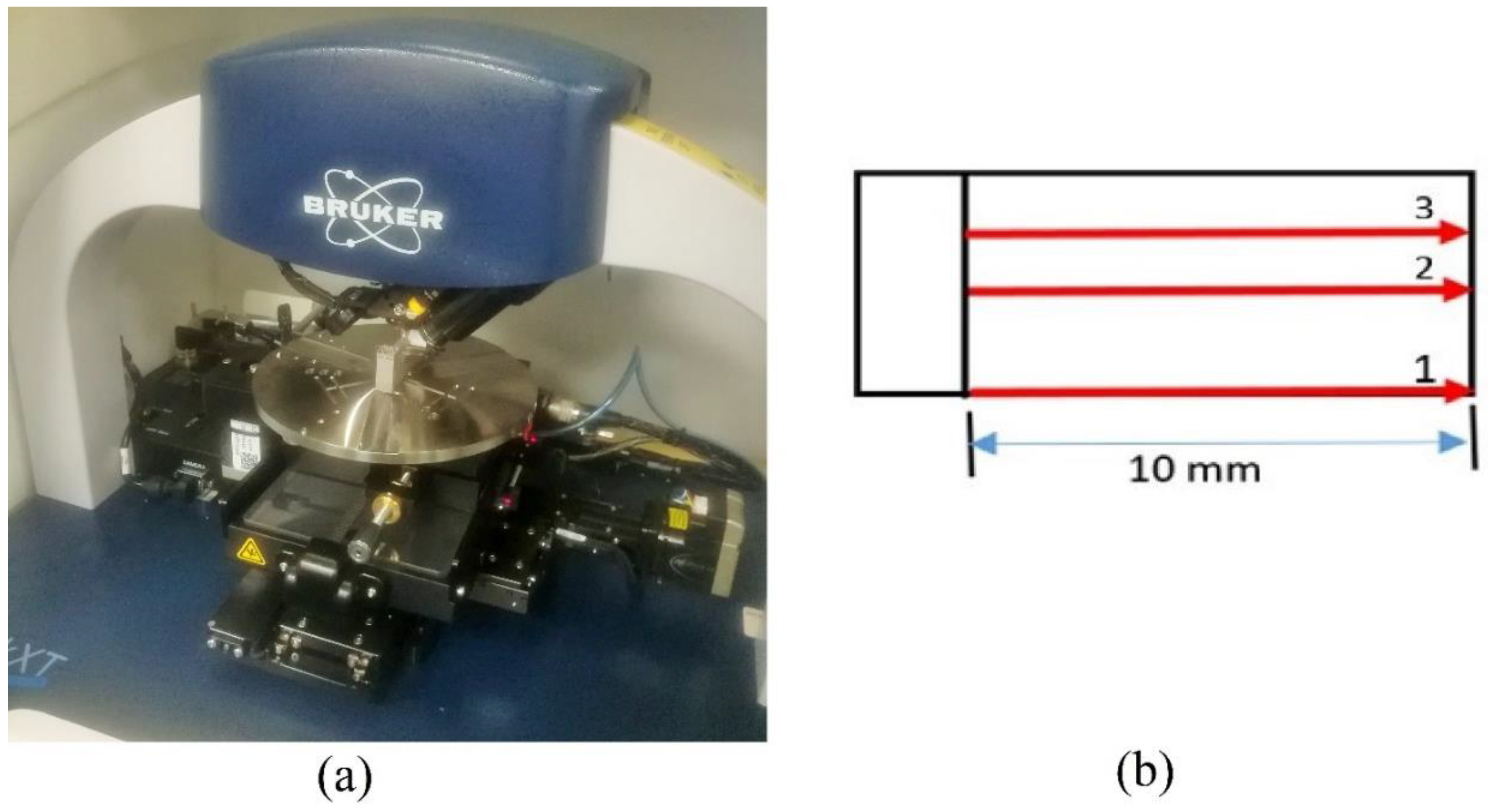
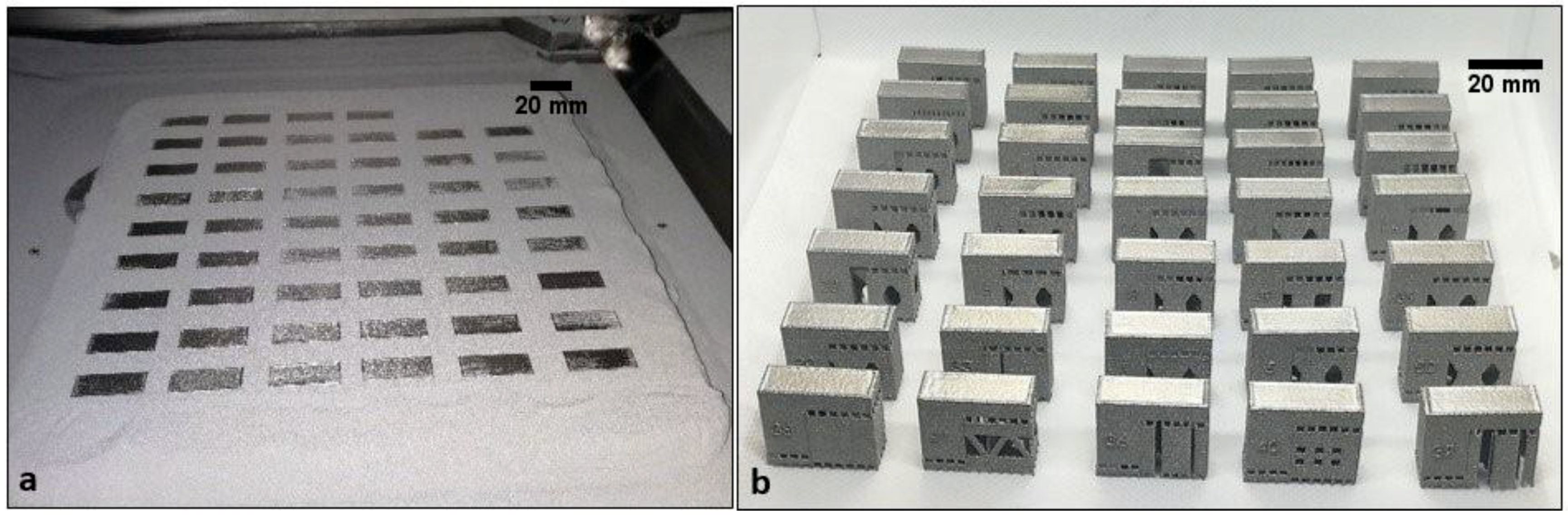
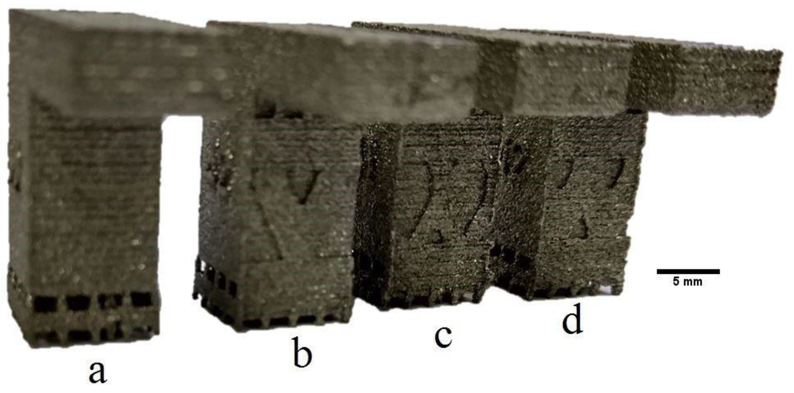
2. Experimental Procedures

In the current study, ledge overhangs with an overhang portion length of 15 mm and a thickness of 5 mm were designed using block support structures in Magics software (Materialise, Leuven, Belgium). ARCAM A2 (Arcam EBM, Mölnlycke, Gottenburg, Sweden) was used to construct the overhang specimens. The support structure design and process parameters were varied to evaluate their effect on support structure removability during the fabrication of the overhang structures. Table 1 lists the design and process parameters, and their corresponding settings.
In the EBM process, after the completion of the build, the specimens were surrounded by sintered powder within the build envelope, as shown in Figure 2a. The build envelope was subjected to a powder recovery system (powder blasting process) to obtain parts free from sintered powder, as shown in Figure 2b.
The fabricated specimens were then subjected to the support structure removal process. To evaluate the effect of support structure design and process parameters on the removability of the support structures, the support structures were removed manually using simple pliers, and the time consumed in removing the support structures for each specimen was recorded. To maintain uniformity, the support structure removal pattern was kept the same for all the specimens and rest time was given after each specimen to avoid the fatigue. The support removal process was started by removing the support tooth and then the support body to make the pliers accessible to the interior tooth. Finally, the supports adhered to the body of the overhang part were removed.
Post processing such as powder and support removal as performed as a last step of the fabrication stage. However, small support removal burrs remain on the supported part surface, which in turn effect the surface quality of the produced part. To evaluate the effect of the addition of a support structure and its parameters on surface quality, surface roughness analysis was carried out by utilizing the Dektak XT surface profiler (Bruker, Germany), as shown in Figure 3. The support teeth, fragmentation and process parameters were considered in this investigation. The surface profiles were measured at three different locations on the supported surface with evaluation length of 10 mm, as shown in Figure 3b, and then the averages were calculated.

3. Results Analysis

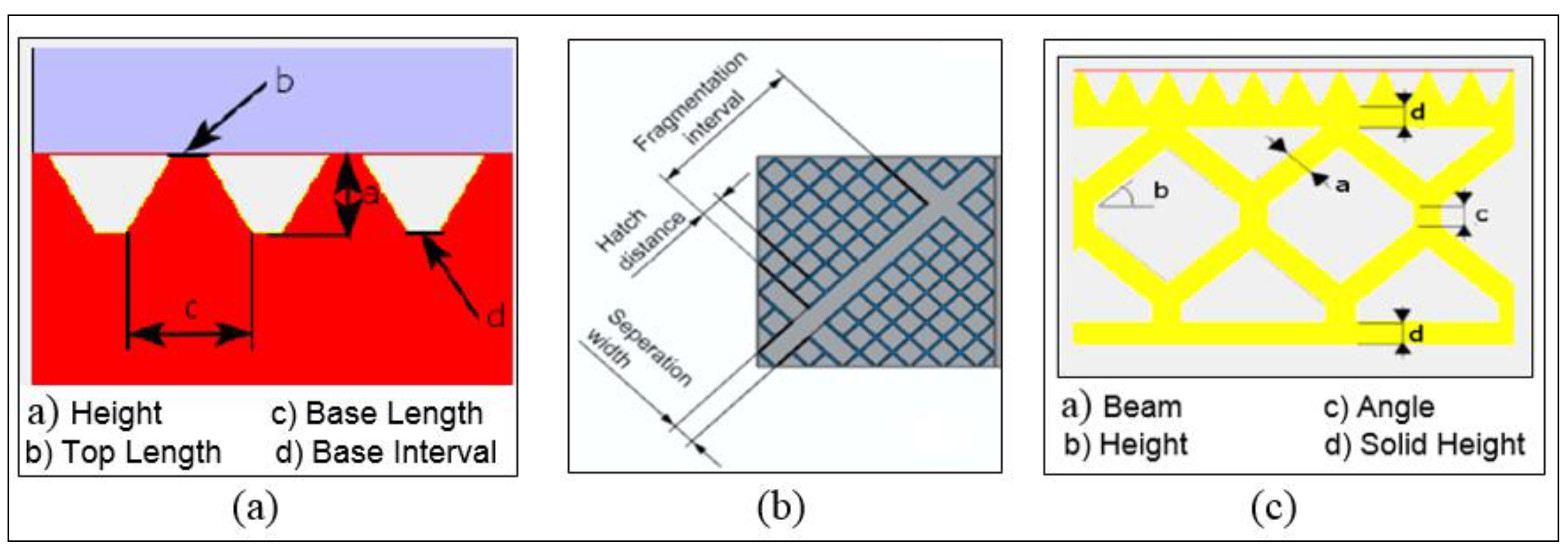
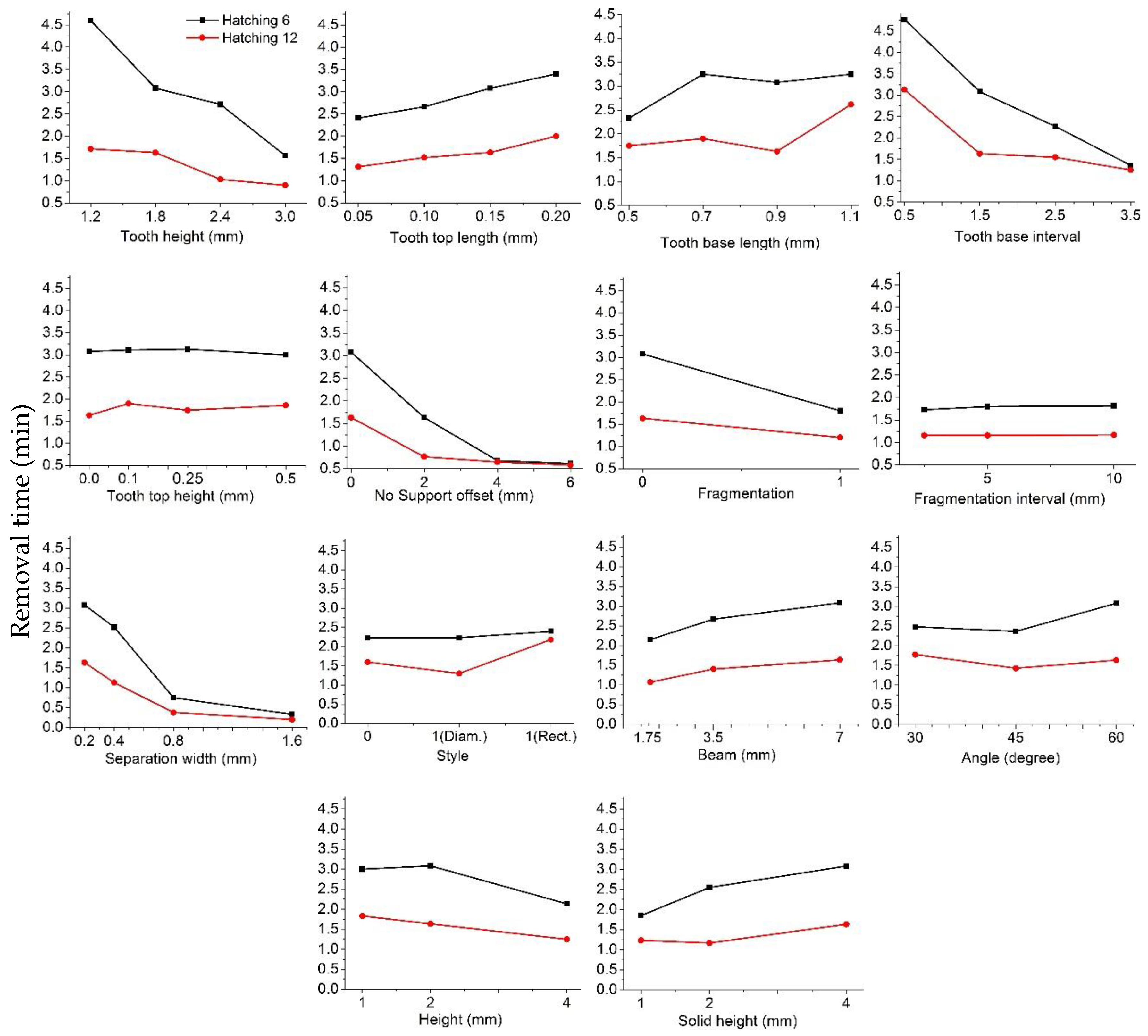
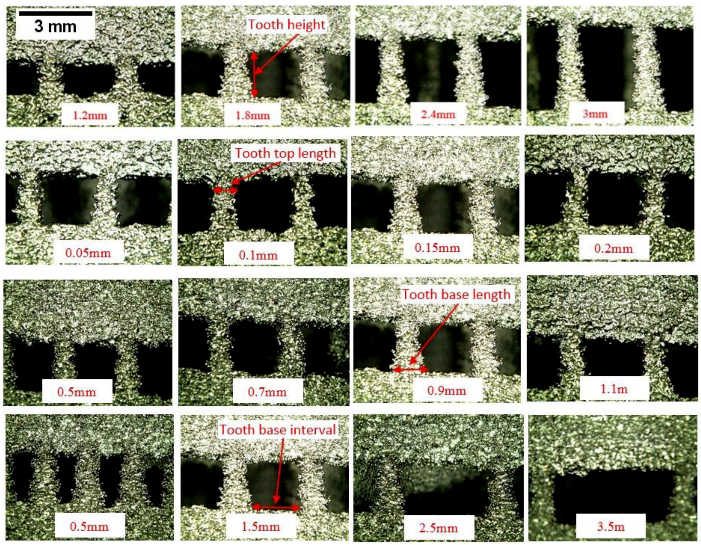
3.1. Effect of Design Parameters

During the support removal process, it was found that the time taken to remove the support structure tooth is very small as compared to the time consumed in removing the support structure body, particularly when some of the support body is adhered to the part surface. In addition, the supports, which are very close to the part surface, affect the surface quality of the part, as shown in Figure 4. Therefore, it is recommended to offset the side support body from the part surface, even by a small distance (no support offset).
It was observed that the support structures with a hatching distance of 6 mm consumed more time to remove than the supports with a hatching distance of 12 mm. This is because of the increase in the number of the support teeth for the 6 mm hatching, which decreases the accessibility of the cutting tool during the removal process. Therefore, the support structures with 6 mm hatching are removed in smaller segments, which result in increased removal time. It was also observed that the sintered powder behind the support walls act as an obstacle to support removability, as shown in Figure 5. To remove the effect of the sintered powder on support structure removability, the powder-blasting process is carried out as and when it is required.
The influence of support structure teeth parameters, hatching, fragmentation parameters and perforation parameters were evaluated in this section. To study the effect of the support tooth parameters on support structure removability, overhangs with different support tooth parameters were constructed and analysed. Teeth parameters after the removal of the sintered powder are presented in Figure 6.
The effect of support design parameters on the support removal time for 6 and 12 mm hatching distances supports is shown in Figure 7. Tooth height, tooth top length, tooth base interval, no support offset and separation width were found to have significant effect on the support removal time. Whereas the other factors had little or no effect on the removability. The support removal time decreases with increase in the tooth height, this is because the increase in the tooth height increases the accessibility of the cutting tool (pliers) and reduces the need to remove the support body to reach all teeth. In addition, with increased tooth height, the non-melted powder around the tooth is easily removed during powder blasting, thereby easing the support removal. Regarding the effect of the tooth top and base length, the support removal time increases with increase in tooth top length. This is because the tooth strength increases with increase in tooth top length. However, the tooth base length did not have a significant effect on support removal time. The results also found that the support tooth interval has a significant effect on the support removal time. As the tooth interval increases, the support removal time decreases. This is because as the support tooth interval increases, the total number of teeth decrease, and the removal tool accessibility increases, which results in easier support removal.
Reducing the support structure volume through the increase of no support offset has a significant effect on the support removal time. As the no support offset increases, the support removal time decreases significantly. This is due to the decrease in the supported area and increase in the accessibility of the cutting tool during the support removal. In addition, the elimination of the contact between the support structure wall and side surface of the part facilitates the support removal process, which results in reduced support removal time.
The effect of the hatching distance in the x- and y-directions on support structure removability is shown in Figure 8. It can be seen that at lower hatching distance, the support removal time is significantly high. This is because the lower hatching distance results in greater support structure, and the support-part contact area decreases the removability of the non-melted powder and accessibility of the support removal tool (pliers).
Implementing the fragmentation design strategy results in subdivision of support structures and slightly improves its removability. It can be seen in Figure 7 that the improvement is higher in the case of the 6 mm hatching distance support, because without the fragmentation strategy, the support body is solid; therefore, the addition of fragmentation strategy results in subdivided support blocks which ease the support removal. Whereas in the case of the 12 mm hatching distance, the perforation strategy is present by default even without the fragmentation strategy. The application of the fragmentation strategy results in the elimination of the perforation strategy. Therefore, there is very little effect on support removal time.
In addition, it was found that the fragmentation separation width has a significant effect on the removability of support structures. As the fragmentation separation width increases, the support removal time decreases. This is due to the decrease in the supported surface, increasing the accessibility of the removal tool and separating the supports into contiguous blocks that are easy to remove, as shown in Figure 9.
Application of perforation strategy results in new support structure configurations, wherein the supports have holes, which make them weaker as compared to the solid supports and they consume less material. The effect of perforation style, beam, angle, height, and solid height on support removability in the 6 and 12 mm hatching distance specimens is shown in Figure 7. The diamond-style perforation had no effect on support removal time in the 6 mm hatching case, because there is no change in the geometry of the support. However, in the case of the 12 mm hatching distance support, the diamond-style perforation resulted in a decrease in the support removal time. Rectangular-style perforation was found to have a negative effect on support removal time, owing to the disintegration of the body of the built support into small pieces, which consumes more time.
Figure 7 shows the influence of the perforation beam on support removability. As the perforation beam increases, the time required to remove the support increases. This is due to the reduction in the perforation holes, which in turn results in the increase in support body strength. It was also found that the default perforation angle of 45° performed better than other angles in terms of support removal time. Regarding the effect of perforation height and perforation solid height, it is found that an increase in the perforation height resulted in the slight decrease in support removal time, causing a decrease in solid-wall support and an increase in hole size, and vice versa, for perforation solid height, as shown in Figure 7.
An ANOVA test with 95% confidence was performed to determine the significance of the selected parameters. Results of 6 and 12 mm hatching are presented in Table 2 and Table 3, respectively.
In case of 6 mm hatching distance supports, most of the selected factors were found to have significant effects (p < 0.05) on the support removal time. The factors such as tooth top length, tooth base length, tooth top height and fragmentation interval were found to have no significant effect on the support removal time, as shown in Table 2. However, in case of 12 mm hatching distance supports, all the factors except the fragmentation interval were found to have significant effect on the support removal time.

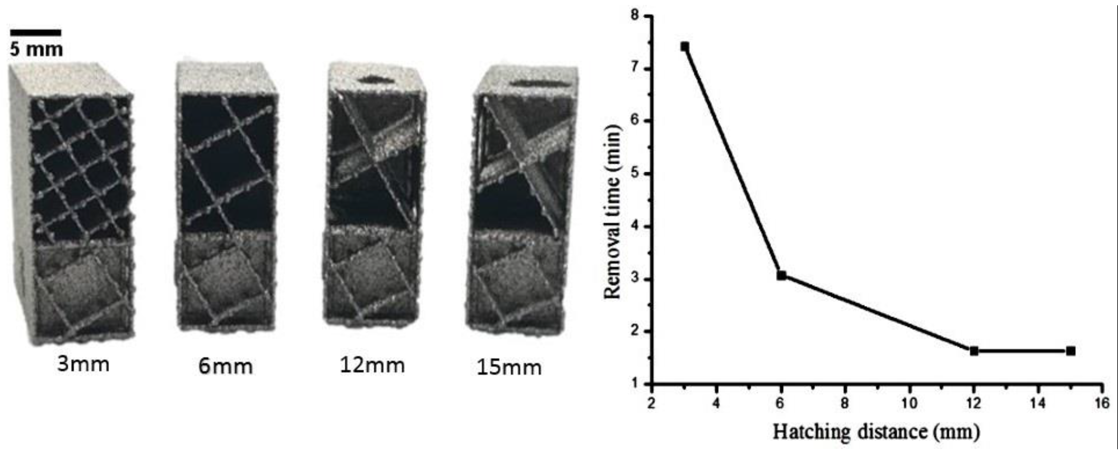
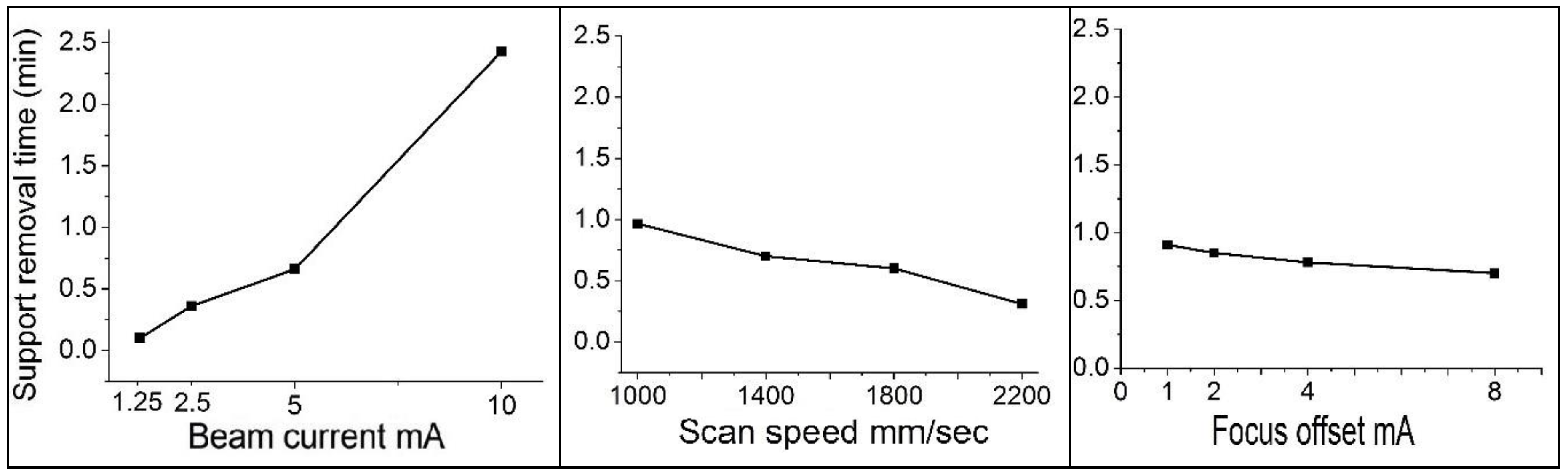
3.2. The Influence of Process Parameters

The effect of the EBM process parameters on support structure removability is shown in Figure 10. It was found that as the beam current increases, the support removal time increases. This is due to the fact that as the beam current increase, the input energy into the supports increase, which in turn, increases the support strength, thereby increasing the support removal time. In case of scan speed, it was found that as the scan speed increases the support removal time decreases. Focus offset was found to have a little or no effect on the removal time, as shown in Figure 10.
A beam current of 1.25 mA in the specimen labelled C1 resulted in supports wherein the supports were broken during the powder-blasting process, as shown in Figure 11. The support remains were easily removed by hand owing to the low strength of supports due to the low input energy. It was observed that the increase in current from 1.25 to 2.5 mA resulted in supports that could withstand powder blasting but were very easy to remove. A further increase in the beam current resulted in supports with considerable strength and significantly higher support removal times.
Regarding the effect of the scan speed as the scan speed increases, the energy flux decreases, which reduces the support strength. The support structure of specimen S4 (speed = 2200 mm/s) had the lowest strength and was most easy to remove. Some of its support was broken during the powder-blasting process.
The results of ANOVA tests for the effect of the EBM process parameters on support removability are shown in Table 4. It is clear that the beam current and scan speed have a significant effect on the removal time. Whereas, focus offset was found to have no significant effect on support removal time.

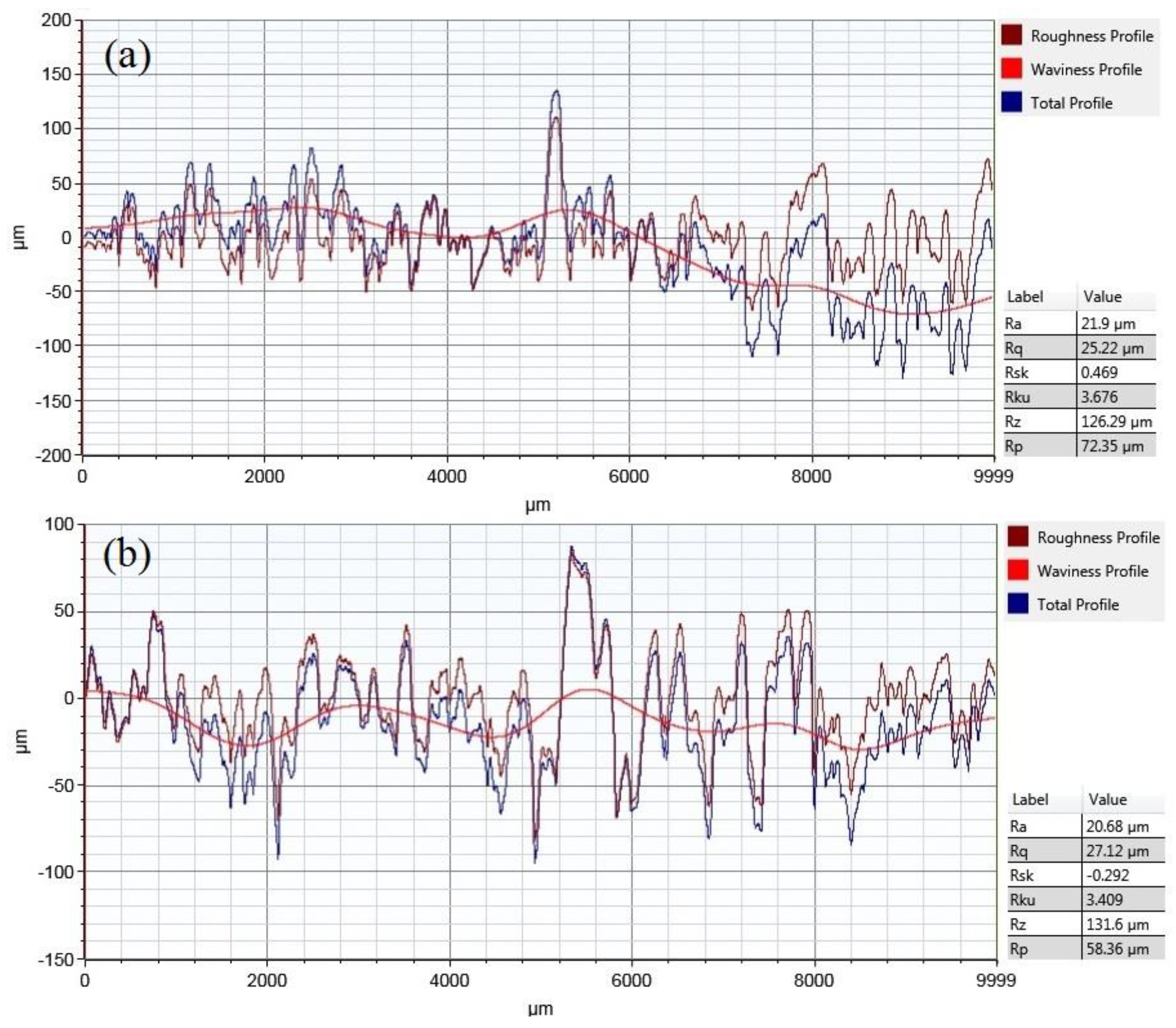
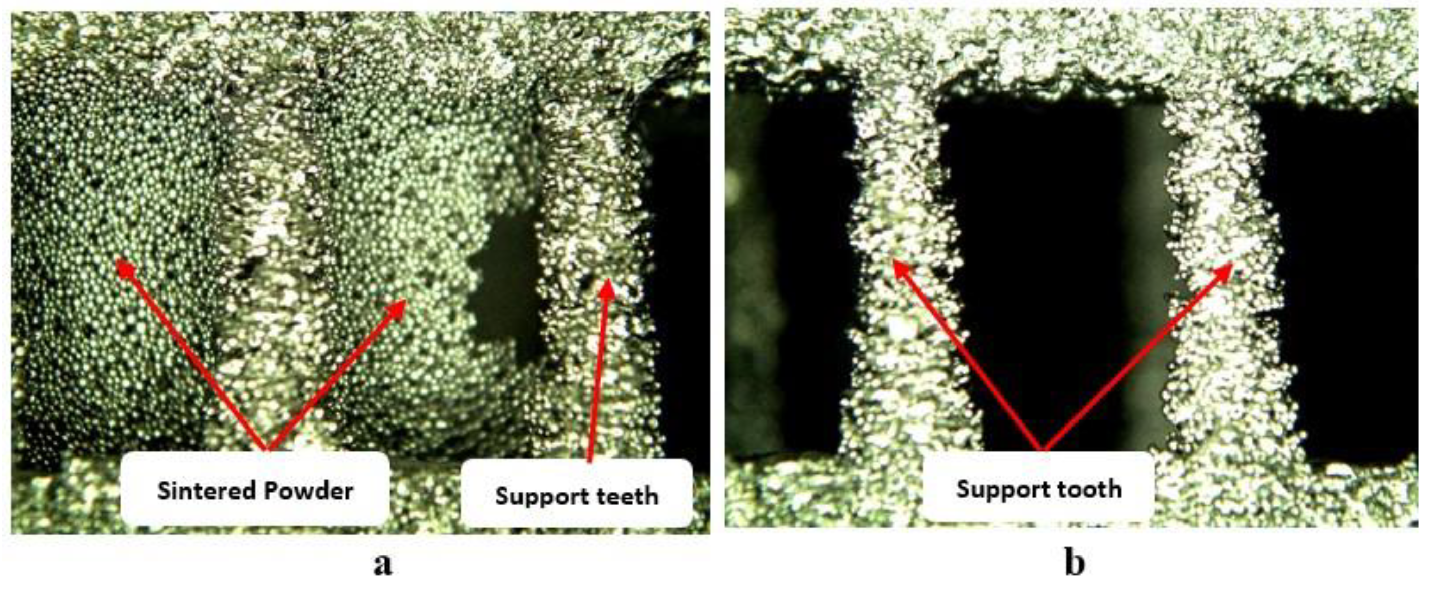
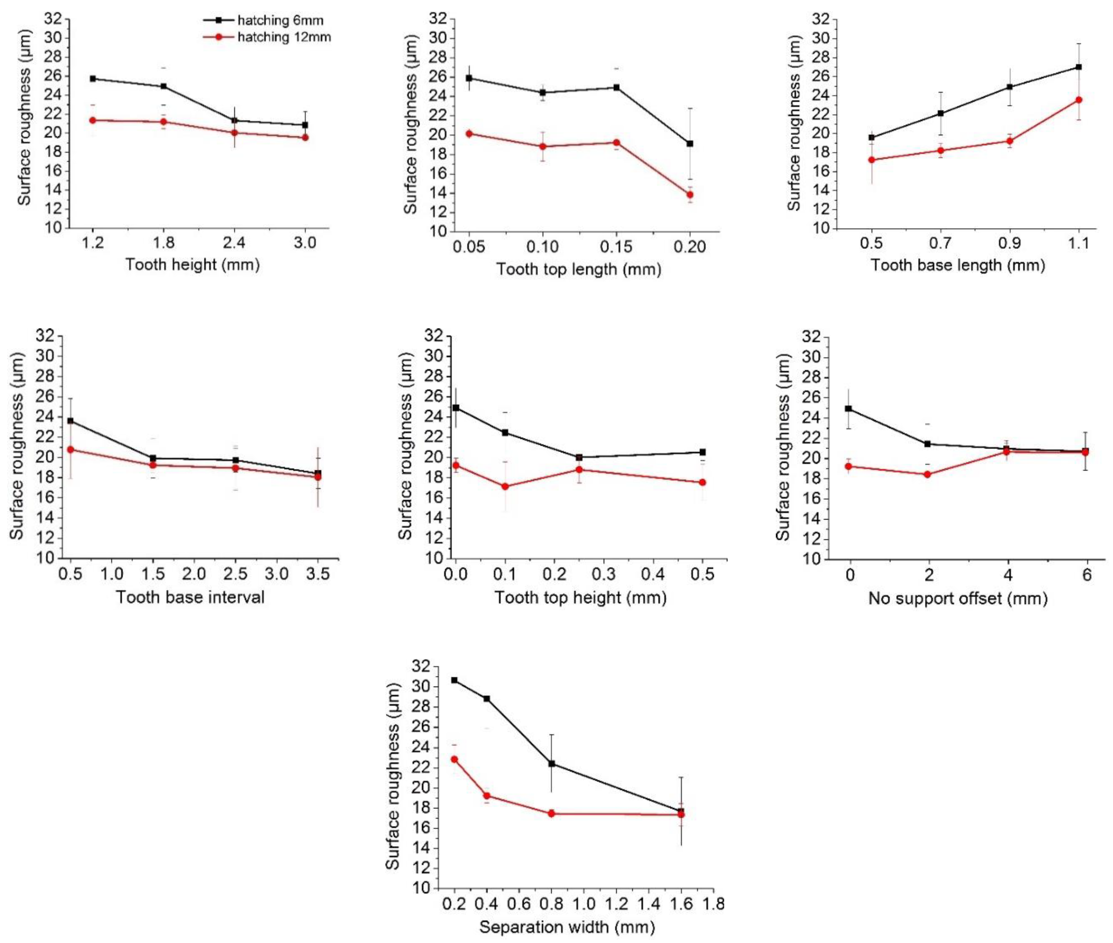
3.3. Surface Roughness

Support structure parameters were found to have an effect on the surface roughness of the overhangs. In general, 6 mm hatching support structures resulted in higher surface roughness, as compared to 12 mm hatching support structures, as shown in Figure 12. This is because of the presence of a greater number of support teeth with the 6 mm hatching supports, than with the 12 mm hatching supports. Tooth top length, tooth base length and separation width were found to have significant effect on the surface roughness. The surface roughness decreases with increases in tooth top length and separation width. Whereas it increases with increases in tooth base length, as shown in Figure 12.
The surface profiles of the samples with minimum support removal time (0.2 min) and maximum support removal time (4.77 min) are shown in Figure 13a,b, respectively. The surface roughness results showed the Ra of 21.9 µm for the sample with minimum support removal time, whereas the sample with maximum support removal time resulted in Ra of 20.68 µm. It was found that the support structure parameters that resulted in minimum support removal time did not have any adverse effect on the surface quality of the overhangs and that the surface roughness was similar to the samples built with other parameters.

4. Conclusions

In the current study, the effect of support design and process parameters on support structure removability was evaluated during the additive manufacturing of Ti6Al4V overhangs via electron beam melting. In general, the results show that the design and process parameters of the support structures have a significant effect on support removability. It was found that with the appropriate selection of design and process parameters for the support structures, it is possible to reduce the support removal time and protect the part surface quality. The results show that support removability can be improved significantly with help of proper support design parameters by reducing the supported area, decreasing the strength of the part/support contact area, and decreasing the strength of the support structure body. Process parameters, such as beam current and scan speed, were found to have a more significant effect on support structure removability as compared with beam focus offset.
Based on the current study the following conclusions can be drawn:
  • As compared to the default support tooth parameters, 3 mm tooth height, 0.05 mm tooth top length and 3.5 mm tooth base interval were found to significantly reduce the support removal time.
  • The fragmented support structure with separation width of 1.6 mm was found to decrease the support removal time by about 80%.
  • The perforation parameters such as 1.75 mm perforation beam, 60° angle, 4 mm height, and 1 mm solid height resulted in around 20% reduction in support removal time, as compared to the default parameters.
  • In case of EBM process parameters, as compared to the default parameters, the beam current of 1.25 mA and scan speed of 2200 mm/sec resulted in more than 80% reduction of support removal time.

Author Contributions

W.A. and A.A.-A. conceived and designed the study. W.A. and M.K.M. conducted the EBM experiments. W.A. conducted the measurements and analysed the results. W.A. and M.K.M. wrote the manuscript and reviewed it. A.A.-A. supervised the work.

Funding

This study received funding from the Raytheon Chair for Systems Engineering. The authors are grateful to the Raytheon Chair for Systems Engineering for funding.

Acknowledgments

The authors thank the Deanship of Scientific Research and RSSU at King Saud University for their technical support.

Conflicts of Interest

The authors declare no conflict of interest.

References

  1. Gu, D.; Meiners, W.; Wissenbach, K.; Poprawe, R. Laser additive manufacturing of metallic components: Materials, processes and mechanisms. Int. Mater. Rev. 2012, 57, 133–164. [Google Scholar] [CrossRef]
  2. Bobbio, L.D.; Qin, S.; Dunbar, A.; Michaleris, P.; Beese, A.M. Characterization of the strength of support structures used in powder bed fusion additive manufacturing of Ti-6Al-4V. Addit. Manuf. 2017, 14, 60–68. [Google Scholar] [CrossRef]
  3. Umer, U.; Ameen, W.; Abidi, M.H.; Moiduddin, K.; Alkhalefah, H.; Alkahtani, M.; Al-Ahmari, A. Modeling the Effect of Different Support Structures in Electron Beam Melting of Titanium Alloy Using Finite Element Models. Metals 2019, 9, 806. [Google Scholar] [CrossRef]
  4. Poyraz, Ö.; Yasa, E.; Akbulut, G.; Orhangul, A.; Pilatin, S. Investigation of Support. Structures for Direct Metal. Laser Sintering (DMLS) of IN625 Parts; International Solid Freeform Fabrication Symposium: Austin, TX, USA, 2015. [Google Scholar]
  5. Cheng, B.; Chou, Y.K. Overhang Support Structure Design for Electron Beam Additive Manufacturing. In Proceedings of the ASME 2017 12th International Manufacturing Science and Engineering Conference Collocated with the JSME/ASME 2017 6th International Conference on Materials and Processing, Los Angeles, CA, USA, 4–8 June 2017. [Google Scholar]
  6. Jhabvala, J.; Boillat, E.; André, C.; Glardon, R. An innovative method to build support structures with a pulsed laser in the selective laser melting process. Int. J. Adv. Manuf. Technol. 2012, 59, 137–142. [Google Scholar] [CrossRef]
  7. Gibson, I.; Rosen, D.W.; Stucker, B. Additive Manufacturing Technologies; Springer: Berlin, Germany, 2010. [Google Scholar]
  8. Thomas, D. The Development of Design Rules for Selective Laser Melting; University of Wales: Wales, UK, 2009. [Google Scholar]
  9. Pullin, J.; Offen, A. Back to the Drawing Board-Addressing the design issues of RM. In Proceedings of the Time Compression Technologies Rapid Manufacturing Conference 2008, Coventry, West Midlands, October 2008. [Google Scholar]
  10. Sames, W.J.; List, F.; Pannala, S.; Dehoff, R.R.; Babu, S.S. The metallurgy and processing science of metal additive manufacturing. Int. Mater. Rev. 2016, 61, 315–360. [Google Scholar] [CrossRef]
  11. Das, P.; Mhapsekar, K.; Chowdhury, S.; Samant, R.; Anand, S. Selection of build orientation for optimal support structures and minimum part errors in additive manufacturing. Comput. Aided Des. Appl. 2017, 14, 1–13. [Google Scholar] [CrossRef]
  12. Bibb, R.; Eggbeer, D.; Williams, R. Rapid manufacture of removable partial denture frameworks. Rapid Prototyp. J. 2006, 12, 95–99. [Google Scholar] [CrossRef]
  13. Ameen, W.; Al-Ahmari, A.; Mohammed, M.K.; Mian, S.H. Manufacturability of Overhanging Holes Using Electron Beam Melting. Metals 2018, 8, 397. [Google Scholar] [CrossRef]
  14. Williams, R.E.; Melton, V.L. Abrasive flow finishing of stereolithography prototypes. Rapid Prototyp. J. 1998, 4, 56–67. [Google Scholar] [CrossRef]
  15. Byun, H.-S.; Lee, K.H. Determination of the optimal part orientation in layered manufacturing using a genetic algorithm. Int. J. Prod. Res. 2005, 43, 2709–2724. [Google Scholar] [CrossRef]
  16. Piili, H.; Happonen, A.; Väistö, T.; Venkataramanan, V.; Partanen, J.; Salminen, A. Cost Estimation of Laser Additive Manufacturing of Stainless Steel. Phys. Procedia 2015, 78, 388–396. [Google Scholar] [CrossRef]
  17. Calignano, F. Design optimization of supports for overhanging structures in aluminum and titanium alloys by selective laser melting. Mater. Des. 2014, 64, 203–213. [Google Scholar] [CrossRef]
  18. Kuo, Y.-H.; Cheng, C.-C.; Lin, Y.-S.; San, C.-H. Support structure design in additive manufacturing based on topology optimization. Struct. Multidiscip. Optim. 2017, 57, 1–13. [Google Scholar] [CrossRef]
  19. Järvinen, J.P.; Matilainen, V.; Li, X.; Piili, H.; Salminen, A.; Mäkelä, I.; Nyrhilä, O. Characterization of effect of support structures in laser additive manufacturing of stainless steel. Phys. Procedia 2014, 56, 72–81. [Google Scholar] [CrossRef]
  20. Safdar, A.; He, H.; Wei, L.-Y.; Snis, A.; Chavez de Paz, L.E. Effect of process parameters settings and thickness on surface roughness of EBM produced Ti-6Al-4V. Rapid Prototyp. J. 2012, 18, 401–408. [Google Scholar] [CrossRef]
  21. Schwerdtfeger, J.; Singer, R.F.; Körner, C. In situ flaw detection by IR-imaging during electron beam melting. Rapid Prototyp. J. 2012, 18, 259–263. [Google Scholar] [CrossRef]
  22. Mahale, T.R. Electron Beam Melting of Advanced Materials and Structures, Mass Customization, Mass Personalization. Ph.D. Thesis, North Carolina State University, Raleigh, CA, USA, 2009. [Google Scholar]
Figure 1. Design parameters: (a) tooth parameters, (b) fragmentation parameters, (c) perforation parameters.
Metals 09 01211 g001
Figure 2. Fabricated specimens: (a) specimens on sintered powder; (b) specimens after sand blasting.
Metals 09 01211 g002
Figure 3. Surface roughness measuring (a) Dektak XT surface profiler; (b) specimen measured surface.
Metals 09 01211 g003
Figure 4. Overhang side surface quality: (a) No support offset; (bd) layers of support adhesion on the overhang wall.
Metals 09 01211 g004
Figure 5. Support tooth structures: (a) before powder removal; (b) after powder removal.
Metals 09 01211 g005
Figure 6. Support structure teeth parameters.
Metals 09 01211 g006
Figure 7. Effect of support design parameters on support removability.
Metals 09 01211 g007
Figure 8. Effect of hatching distance on support removability.
Metals 09 01211 g008
Figure 9. Support structures with various fragmentation separation widths.
Metals 09 01211 g009
Figure 10. Effect of EBM process parameters on support removability.
Metals 09 01211 g010
Figure 11. Specimen C1 (current = 1.25 mA) (a) before powder-blasting process, and (b) after powder-blasting process.
Metals 09 01211 g011
Figure 12. Effect of support parameters on surface roughness.
Metals 09 01211 g012
Figure 13. Surface roughness profiles: (a) minimum support removal time; (b) maximum support removal time.
Metals 09 01211 g013
Table 1. Support structure design and process parameters.
Support Structure ParametersLevel 1Level 2Level 3Level 4
Design parametersTooth and No Support Offset ParametersTooth height (mm) 1.21.802.43
Tooth top length (mm)0.050.10.150.2
Tooth base length (mm)0.50.70.901.1
Tooth base interval0.51.502.53.5
Z offset (mm)00.50.10.25
No support offset (mm)0246
Hatching and Fragmentation ParametersX and Y hatching (mm)361215
Fragmentation 01--
Fragmentation interval (mm)2.5510-
Separation width (mm)0.20.40.81.6
Perforation ParametersPerforation style 01 (Diam.)1 (Rect.)-
Perforation beam (mm)1.753.57-
Perforation angle 304560-
Perforation height (mm)124-
Perforation solid height (mm)124-
Process parametersProcesses ParametersCurrent (mA) 1.52.5510
Scan speed (mm/s)1000140018002200
Focus offset (mA) 1244
Table 2. ANOVA for support removability with respect to the support design parameter (hatching 6).
SourcedfSum of SquaresMean SquareF-Valuep-Value Prob > F
Model3436.4111.07113.88<0.0001
Linear3436.4111.07113.88<0.0001
Tooth height34.6981.56620.29<0.0001
Tooth top length30.6130.2042.650.093
Tooth base length30.5750.1922.480.107
Tooth base interval36.3412.11427.39<0.0001
Tooth top height30.0220.0070.090.962
No support offset310.5583.51945.60<0.0001
Fragmentation12.2552.25529.23<0.0001
Fragmentation interval20.0890.0450.580.575
separation width35.0211.67421.69<0.0001
Style20.8370.4195.420.019
Beam20.7530.3774.880.026
Angle20.5920.2963.840.049
Height20.7120.3564.610.031
Solid height21.3680.6848.860.004
Error131.0030.077--
Total4737.415---
Table 3. ANOVA for support removability with respect to the support design parameter (hatching 12).
SourcedfSum of SquaresMean SquareF-Valuep-Value Prob > F
Model3412.2750.36145.08<0.0001
Linear3412.2750.36145.08<0.0001
Tooth height30.7460.24931.06<0.0001
Tooth top length30.2500.08310.420.001
Tooth base length30.9890.33041.17<0.0001
Tooth base interval32.3710.79098.70<0.0001
Tooth top height30.1410.0475.850.009
No support offset32.1330.71188.77<0.0001
Fragmentation10.4690.46958.52<0.0001
Fragmentation interval20.0000.0000.000.997
separation width31.4900.49762.03<0.0001
Style20.3100.15519.38<0.0001
Beam20.2930.14718.31<0.0001
Angle20.0610.0313.820.049
Height20.1760.08810.960.002
Solid height20.2840.14217.71<0.0001
Error130.1040.008--
Total4712.379---
Table 4. ANOVA for the effect of EBM process parameters on support removability.
SourcedfSum of SquaresMean SquareF-Valuep-Value Prob > F
Model93.6910.410109.840.009
Linear93.6910.410109.840.009
Current33.3541.118299.480.003
Scan speed30.2280.07620.330.047
Focus offset30.0400.0133.610.224
Error20.0070.004--
Total113.698---

