Article

Tensile and Creep Properties Improvement of Ti-6Al-4V Alloy Specimens Produced by Electron Beam Powder Bed Fusion Additive Manufacturing

1
Dipartimento di Ingegneria, Università di Messina, 98166 Messina, Italy
2
Dipartimento di Ingegneria Civile e Architettura, Università di Catania, 95123 Catania, Italy
*
Authors to whom correspondence should be addressed.
Metals 2019, 9(11), 1207; https://doi.org/10.3390/met9111207
Submission received: 30 September 2019 / Revised: 1 November 2019 / Accepted: 5 November 2019 / Published: 9 November 2019

Abstract

:
Thanks to their excellent mechanical strength in combination with low density, high melting point, and good resistance to corrosion, titanium alloys are very useful in many industrial and biomedical fields. The new additive manufacturing methods, such as Electron Beam Powder Bed Fusion based on the deposition of metal powders layers progressively molten by electron beam scanning, can overcome many of the machining problems concerning the production of peculiar shapes made of Ti alloys. However, the processing route is strictly determinant for mechanical performance of products, especially in the case of Ti alloys. In the present work flat specimens made of Ti-6Al-4V alloy produced by Electron Beam Powder Bed Fusion (or Electron Beam Melting) have been built and post-processed with the purpose of obtaining good tensile and creep performance. Preliminarily, the process parameters were set according to literature evidence and machine producer recommendations, validated by the results of a thermal analysis, aimed at satisfying the best processing conditions to reduce defects, as unmelted regions, microstructure coarsening or porosity, that are detrimental to mechanical behavior. Subsequently, Hot Isostatic Pressing and surface smoothing were considered, respectively, in order to reduce any internal porosity and lower roughness. Microstructure of the investigated specimens was characterized by optical and scanning electron microscopy observations and by X-ray diffraction measurements. Results show enhanced tensile behavior after the hot pressing treatment that allows to relieve stresses and reduce defects detrimental to mechanical properties. The best ductility was obtained by the combined effects of machining and densification. Creep test results verify the beneficial effects of surface smoothing.

1. Introduction

Titanium alloys are widely used in many fields, such as in the chemical, automotive, and aerospace industries, thanks to their excellent mechanical strength (especially considering their low density and high melting point), together with the ability to maintain it within a wide range of temperatures which make these alloys particularly suitable for engine parts. The experience shows that titanium alloys also have high reliability in seawater corrosion resistance: pipes and fittings made of titanium can reduce weight and extend significantly their life. So, titanium applications are more reasonable if its high cost is compensated by long lifetime, especially when repair and maintenance service are difficult to perform [1]. Besides these properties, the non-toxicity of titanium makes it also useful for biomedical applications (implant devices, pacemakers, artificial hearts) [2]. However, the high hardness and low machinability of Ti alloys affect their feasibility by conventional processes [3], encouraging the research for new methods, as pointed out in Reference [4], for vibration cutting. Machinability problems can be overcome by additive manufacturing, that includes a variety of technologies, applied for more than 20 years for porous structures and prototypes, some of which promise to become commonly used to produce near-net-shape components of complex geometry reducing production time and cost [5].
The increasing demand for metal components with complex shapes and high quality is a strong motivation for the development of additive manufacturing. This new technology is based on an incremental layer by layer approach [1], unlike conventional manufacturing that utilizes subtractive methods. Most relevant techniques of additive manufacturing use powder or wire as a feedstock to be selectively molten by a focused heat source and then solidified during the subsequent cooling. This process is repeated layer by layer until the final form is obtained [6,7].
Several additive manufacturing techniques are specifically addressed to metallic materials. Between them, both powder bed fusion processes, Laser Powder Bed Fusion (L-PBF) or Selective Laser Melting (SLM), and Electron Beam Powder Bed Fusion (EB-PBF) or Electron Beam Melting (EBM), have been developed and widely experimented over the past years [8], attracting the attention of the industry for their immanent advantages, first of all the unrivalled design freedom in short processing times [9]. By these methods, it has become possible to reliably manufacture both dense and cellular parts in complex three-dimensional shapes for a number of materials, including steel, aluminium, and titanium [10].
L-PBF and EB-PBF have the same working principles, employing a layer by layer technology with fusion of powder particles through a focused heat source due to a laser or an electron beam, giving rise to high cooling rate and consequently to finer microstructure if compared to the usual casting methods (see the microstructure predictive model developed in Reference [11]). In general, this results in higher tensile properties, even if manufactured products are affected by microporosity causing a decrease of elongation respect to wrought products. Nevertheless, the use of various energy sources requires different processing conditions and subsequently produces distinct characteristic features [12]: L-PBF process is performed in an inert gas atmosphere, while EB-PBF in vacuum conditions to avoid the electron beam deflection. During L-PBF, powder particles absorb heat energy from photons, while the electron beam penetrates inside powder converting its kinetic energy into thermal energy. An electron beam has a wider spot size than a focused laser spot, consequently minimum resolution, feature size and surface finish of EB-PBF products are typically less fine than that of L-PBF ones. In particular, L-PBF works with scan speeds around 0.4 m/s, which is a lower order of magnitude than that used in EB-PBF, so the latter results faster at the expense of surface finish [13]. On the other hand, the EB-PBF is more energy-efficient than laser technology, and vacuum allows for better processing of reactive metals. Moreover, L-PBF works on a cold powder bed, while EB-PBF operates on a preheated bed in order to achieve a slight sintering of the powder particles and counteract electrostatic charging. Consequently, there are different crystallization conditions for the two methods. In general, the highest cooling rates, reached during the L-PBF process, enhance mechanical strength; however, the highest temperature gradients due to L-PBF, in comparison to EB-PBF, led to internal stress at small scale level [14].
Ti alloys products can be quickly manufactured via L-PBF or EB-PBF, without the usual problems associated with conventional machining, such as heat generation, friction, use of many tools, and consequent long production time and considerable waste of materials. Since EB-PBF operates in vacuum conditions, there are great advantages in the case of Ti powder, because this element has high affinity for oxygen [15]. Moreover, thanks to preheating, components produced by EB-PBF are subject to lower thermal gradients, and as a consequence they are characterized by moderate onset of micro-fractures due to thermal variations, and limited residual stresses due to not uniform heating [16]. On the other hand, EB-PBF manufactured components suffer with poor surface quality due to rough finishing [17]. In any case, manufactured parts produced by melting of a powder bed are characterized by lack of fusion defects generated during the production process and by entrapped gas porosity inside powder particles. In order to relieve stresses and to reduce any remaining porosity detrimental to mechanical properties it is worth to treat L-PBF or EB-PBF products by Hot Isostatic Pressing (HIP) [18,19]. Such successful porosity closure is related to self-diffusion occurred during the applied heat treatment under very high isostatic pressure [19].
Ti-6Al-4V, also known as TA6V or Ti64, is the most common Ti alloy, representing more than 50% of the Ti market [1]. Typical applications can be fracture-critical parts, low and high temperature components and structures (such as airframe, pressure and submarine vessels, heat-exchangers, structural parts, and engine components, compressor, and turbine blades).
The two main alloying elements have different behavior, being Al and V, respectively, α-phase and β-phase stabilizer. Therefore, Ti-6Al-4V falls in the category of the α+β titanium alloys that show different microstructures and consequently mechanical properties, according to thermal history that determines the amount and arrangement of the α and β phases. This is one of the reasons why electron beam melted Ti-6Al-4V alloy is strictly influenced by process parameters. Depending on the process conditions and the product size, EB-PBF gives rise to such a thermal distribution in melting phase which, combined with fast directional solidification, at high cooling rate from temperatures higher than the β-transus, results in fine lamellar microstructures with “basket weave” morphology or less usually in a martensitic acicular morphology. Furthermore, EB-PBF process parameters are determining not only for bulk microstructural features, but for surface features also, in both cases with consequent effects on mechanical properties [20,21]. Surface conditions are affected by powder grain size also: in general, it gives rise to considerable surface roughness that is appreciated in surgery implants supporting osseo-integration but reduces strength and ductility.
Extensive efforts have been made with regard to the characterization of tensile properties of Ti-6Al-4V EB-PBF products, which have resulted in being clearly affected by microstructure features as well as surface status and internal porosity. Detailed overviews on the state-of-the-art report extended data collection, taking into account different conditions of the specimens tested at room temperature (as build, machined, heat treated) and the effect of their orientation in building process [22,23,24]. A recent paper [25] dealt with microstructural, mechanical characterization and creep behavior of flat specimens made by the same alloy powder grade (Ti-6Al-4V ELI Grade 23) and processed by the same machine (EBM Arcam Q10) used in the present work, considering two different orientations of powder deposition: layers parallel or orthogonal to the tensile test axis. The best tensile properties, both at room temperature and in the range between 400 and 600 °C, were measured in the first type of specimens, thanks to grain alignment with the tensile direction; this kind of specimen showed the best creep performance at 400 and 600 °C as well. At room temperature, the same difference in tensile behaviour has been detected not only at the conventional quasi-static strain rate conditions, but also at dynamic ones [26].
The present work aims to investigate the potential of some key aspects in the improvement of tensile properties of Ti-6Al-4V flat specimens produced by EB-PBF, preliminarily through an appropriate setting of the process parameters, which takes into account the thermal conditions in powder melting and specimens building by stratification, and then experimenting the combined effects of surface finishing and densification of bulk volume through HIPping. Creep test results are also reported to verify the good effects of smoothing, as well as to contribute in filling a gap in the literature, which most of the time neglects creep behavior, or presents substantially limited data about creep properties of Ti-6Al-4V EB-PBF products [27]. Mechanical characterization was performed on two types of standard specimens with different thickness. The external surfaces were smoothed by manual grinding or by machining. In order to reduce internal porosity and defects, and so enhance mechanical properties, a number of specimens were treated by HIP. Surface conditions were studied by means of confocal microscopy, obtaining 3D mapping and evaluating roughness. Optical microscopy and Scanning Electron Microscopy (SEM) observations were carried out on specimen cross sections after metallographic preparation. For a correct phase identification also X-ray diffraction (XRD) was considered.

2. Materials and Methods

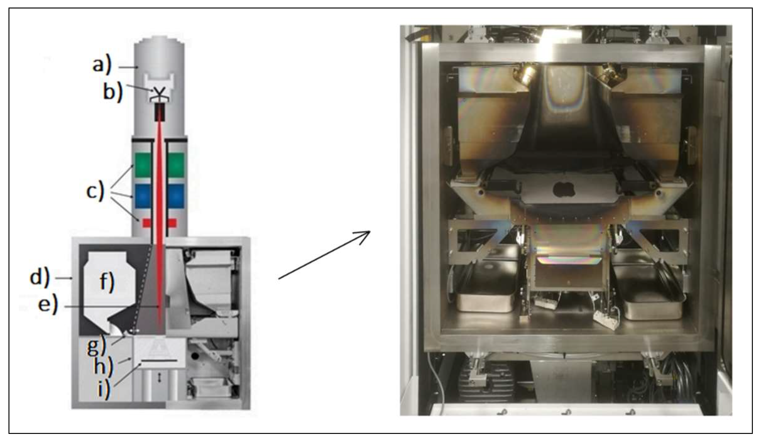
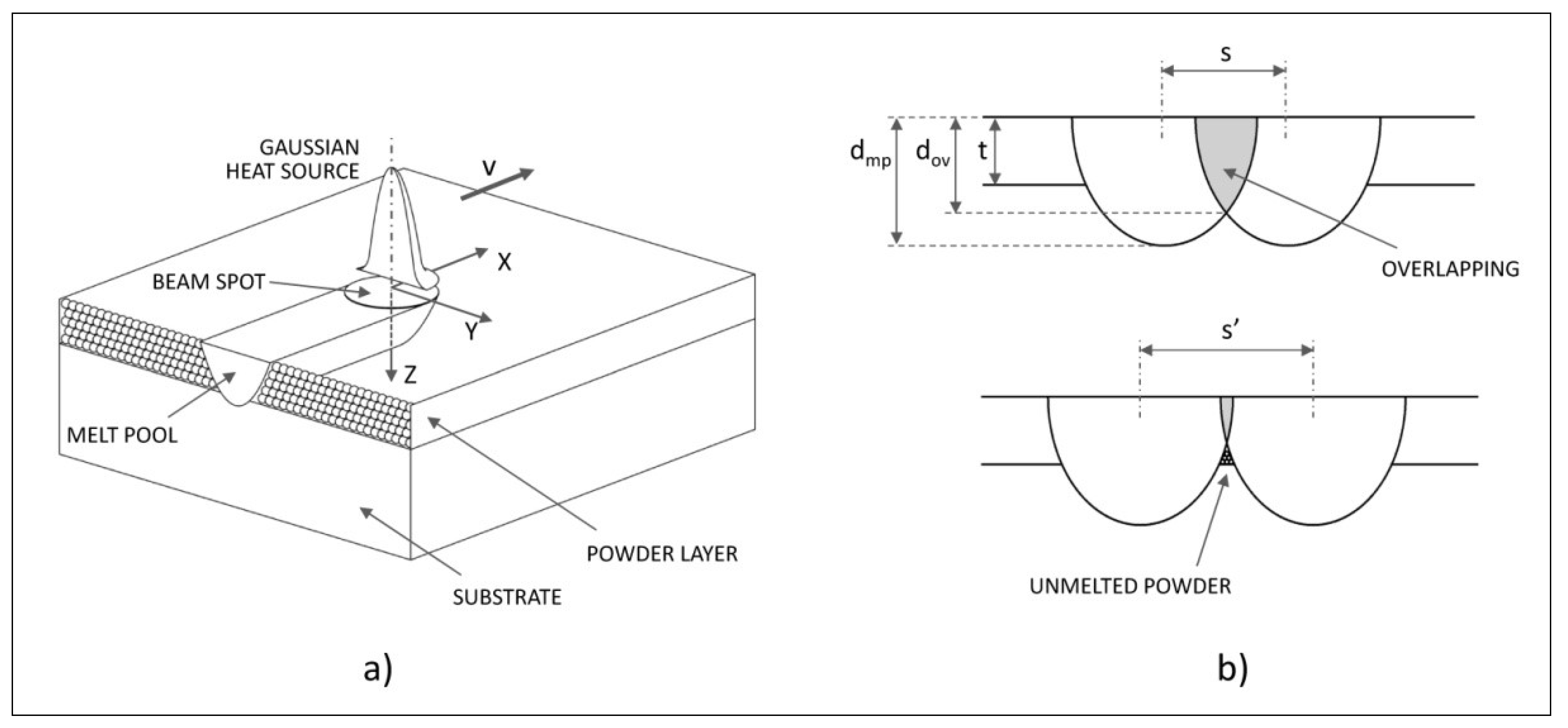
2.1. Thermal Analysis of Electron Beam Powder Bed Fusion (EB-PBF) Process and Efficient Setting Criteria

Electron Beam Powder Bed Fusion (also known as Electron Beam Melting) is an additive technology based on the scan by an electron beam, in order to melt a pre-alloyed metal powders deposited layer by layer in a vacuum chamber. By this way three-dimensional artefacts with massive or cellular structures, controlled density and specific geometries, can be reproduced [28].
Our specimens were made using the EBM Q10 machine (ARCAM AB, Mölndal, Sweden) [29], whose main components are shown in Figure 1; next to the machine scheme, the vacuum chamber used for manufacturing the tested specimens is shown (note the start plate partially covered by a layer of powder).
The process develops according to some sequential steps [30], beginning with heating the start plate before the deposition of the first layer of powder, at a temperature defined on the basis of the powder material. After depositing each layer, the powder bed is preheated by means of a series of non-focused, high-power, and high-speed electronic beam passages. The power and the scanning speed are reduced in the subsequent phase of selective fusion, during which the beam is concentrated. After completing the first layer melting, the process platform is lowered by the thickness of a layer to allow the deposition of a new layer of powders to be processed. The sequence is repeated until the whole component is built.
Unlike other fusion additive processes, EB-PBF provides significant preheating of the powders (600 ÷ 750 °C) before melting, which causes a slight sintering, improves the electrical and thermal conductivity and mechanical stability of the powder bed, and reduces temperature gradients limiting the onset of micro-fractures due to thermal variations [16].
The whole process takes place in vacuum (10−3 Pa) to prevent the air molecules from disturbing the electron beam. During the selective melting phase, a small amount of low-pressure inert gas (helium at 10−1 Pa) is added to avoid the accumulation of electric charges in the powder, and to guarantee the thermal stability of the process. At the end, the gas pressure is increased to facilitate cooling [31].
Microstructure and mechanical properties of EB-PBF products are strongly influenced by process parameters and scanning strategy (pattern of the scanning lines) [32]. These factors impact the complex multi-physics phenomena involved in melting processes based on powder bed fusion by a power beam (L-PBF and EB-PBF), which are not related exclusively to the interaction between beam and powders, producing thermal distribution and consequently peak temperatures, melt pool size, and cooling rate. All this affects solidification process and microstructure morphology.
As basic starting point for quantification of melting phenomena, the input energy density per unit of material volume E (J/mm3) is defined by the following relationship [33]:
E = P v t s
being P (W) the beam power, v (mm/s) the scanning speed, t (mm) the layer thickness and s (mm) the scan spacing (or line offset). In EB-PBF, the beam power P is given by the current intensity multiplied by the acceleration voltage. Increasing input power and/or decreasing scan speed or layer thickness or scan spacing would increase the input energy density and consequently the powder temperature. Combinations of beam power and scanning speed for a range of scan spacing values have different effects not only on heat distribution, but also on chemical composition, porosity and melt surface quality [34].
As creating a fully molten region is very important for producing fully dense parts, sufficient input energy density is required to be applied to the powder material. This required condition can be assessed by calculating the minimum amount of heat Hmin (J/m3) to melt the unit volume of material, which for metals and alloys can be approximated by [35]:
H min 1.5 ρ C p ( T m T 0 )
where ρ is the density (kg/m3), Cp is the specific heat capacity (J/kgK), T0 and Tm are respectively the powder bed and the melting temperatures (K).
Comparing the input energy density, calculated by Equation (1), with the minimum amount of heat required to melt the unit volume of powder at the fixed pre-heating temperature, calculated by Equation (2), it is possible to verify if the beam energy is sufficient to sustain the melting process.
To obtain a really efficient melting of the powder layer, the interaction with the heat source and the consequent thermal distribution must be such to create a melt pool with certain characteristics. The geometry of the processing zone depends not only on the heat source process parameters (beam power, scanning speed, beam width), but also on the material properties that influence the conditions of heat transfer on the surface of the powder layer and inside it.
The relationship between beam process parameters, thermal distribution, and melt pool geometry and depth has been investigated: it is widely traced back to the problem of scanning a material with a heat source, to determine both the thermal distribution and the cooling rate, which are fundamental in determining the final metallurgical structures [36].
The reference model for material scanning in additive electron beam melting process can be summarized, such as in Figure 2a, by a substrate of solid metal and a powder layer on the top of this substrate (both coplanar to the x-y plane of the Cartesian system); the scanning beam is positioned on the z axis and moves along the x axis.
Energy transfer to the powder layer depends mainly on the heat source characteristics. For both laser and electron beams, the radius and the power density distribution are fundamental properties of the heat source. The power density distribution on the powder layer surface within the beam spot, which is expressed as power per surface unit, is generally considered to be characterized by axisymmetric Gaussian profile [37].
The measurement of the temperature fields is difficult because the heat source moves rapidly and the temperature field is highly transient. This is the reason why the thermal analysis are widely conducted by means of numerical simulation [38].
However, analytical formulation for thermal distribution modelling, based on some simplifications, can be defined. It depends not only on the interaction with the moving heat source, but also on the evolution of thermal flow from the heated zone to the colder parts. In general terms the heating transfer process is based on the three mechanisms of conduction, convection, and radiation. In electron beam heating, the most predominant of these mechanisms is the conduction transfer. The convection and radiation losses can be neglected because of the small melted zone and the short heating time.
With these premises, temperature fields prediction models based on conduction mechanism can be used, such as those developed to predict temperature fields due to a moving heat source in the quasi-stationary state, originally based around welding processes, but more recently extended to additive layer manufacture techniques [20,39]. According to this type of modelling approach, considering again the scheme in Figure 2a: in the case of well-focused electron beam with small radius, at a first approximation the heat source can be considered concentrated on the centre of beam spot, that is moving along the x axis direction with a constant speed v; then the temperature distribution around the coordinate system fixed on the movable point source is given by:
T = T o + η P 2 π λ R exp ( v ( x + R ) 2 α )
where To is the powder bed temperature (K), η is the fraction of absorbed beam power, P is the beam power (W), λ is the thermal conductivity (W/mK), α = λ/ρCp is the thermal diffusivity (m2/s), v is the scanning speed (m/s), and R = [x2 + y2 + z2]1/2 is the distance to the heat source.
Through the use of Equation (3), it is possible to conduct an analysis which, although based on simplifying models, provides valid evaluations of the effects that combinations of beam power and scanning speed for a range of scan spacing values, have not only on melt pool geometry and depth, but also on the overall efficiency of heat distribution during melting phase that can be traced back to the optimal overlapping condition between the melt pools of two contiguous scanning lines.
With regard to the melt pool depth, to realize well-built products, a value about twice the layer thickness t is required [40]. Furthermore, as shown in Figure 2b, the limit condition to guarantee a complete melting of the layer requires that the overlapping region exceeds the entire thickness of the layer (above). An increase in the scan spacing (s’ > s) could create un-melted powder region under the adjacent scanning lines (below); as a consequence, the gap of un-melted powder could be trapped inside the material as defects.
Conventionally, a stable condition for optimal parameters setting should guarantee that the depth of the overlapping area dov exceeds the layer thickness t, up to reach twice this value [40]. On the other hand, this extreme upper overlapping condition could result in an excessive layers remelting during scanning process, to be avoided by balancing process parameters: a reduction in remelting results in an even finer microstructure which could give higher strength to the processed material; furthermore, less remelting also reduces the loss of aluminium due to evaporation during the additive process, which is another positive factor in terms of strength properties.
Due to the highly concentrated energy source and extremely short interaction time, high temperature and cooling rate will be produced in the melt pool: the temperature has been estimated to be between 1900 and 2700 °C [41], the cooling rate has been calculated between 103 and 105 K/s [20]. As a consequence, material inside the melt pool undergoes fast solidification, while solidified material of the previous layer is subjected to a temperature (referred to as build temperature), that is substantially coincident with the pre-heating temperature and has a significant effect on microstructure and mechanical properties, because its increase results in a decrease of mechanical properties due to microstructural coarsening [20].

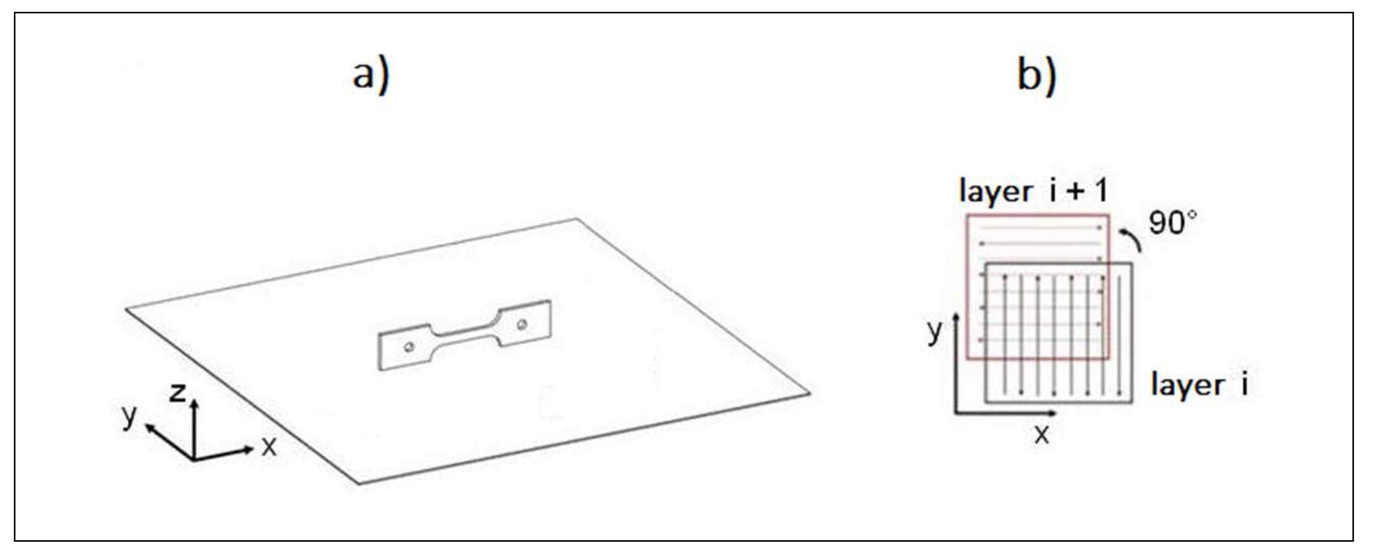
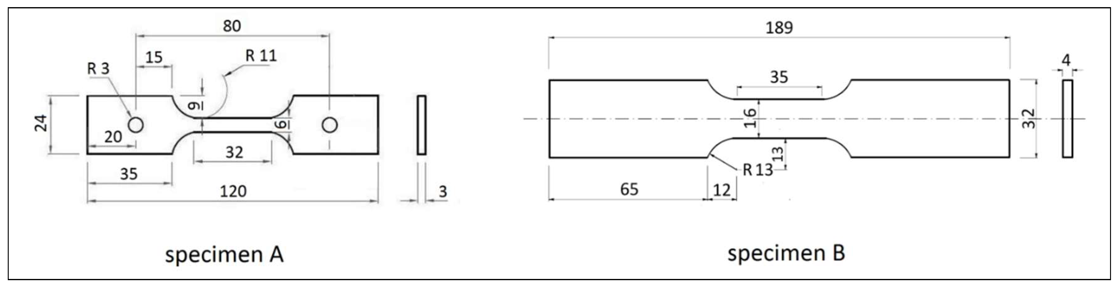
2.2. Materials, Specimens Fabrication, and Experimental Tests

The tensile and creep specimens were printed by EB-PBF, setting the main process parameters as shown in Table 1. They have been preliminarily selected under the indication of the machine producer [29], and taking into account basic guidelines to reduce defects, as surface roughness, porosity, unmelted regions and delamination [38]. In this regard it is interesting to note that the effects of some parameters may be contrasting on different types of defects. An increase in scan speed favors the reduction of surface roughness, but negatively affects porosity and unmelted region. Similarly, for the beam current: its increase is beneficial for reducing the surface roughness, but it involves an increase in the beam power and therefore the energy density also (other parameters in Equation (1) being equal), that is detrimental for limiting delamination. The reduction of the scan spacing, instead, is beneficial for most types of defects (surface roughness, porosity, unmelted region). This confirms the importance of an efficient balancing of process parameters.
The pre-selection of parameters, which made it possible to define the most efficient ranges and alternatives in parameters value setting, has been subsequently refined so to meet the pool depth and overlapping conditions introduced before, using the theoretical analysis of thermal field in melt pool, carried on by means of the simplified analytical formulation introduced in the previous section, whose most relevant results will be detailed in the next Section 3. Based on these results, to avoid microstructural coarsening due to excessive build temperature and layers remelting, a pre-heating temperature of 650 °C has been fixed, and the process parameters have been set in order to guarantee that the maximum pool depth slightly exceeds twice the layer thickness, and the ratio between overlapping depth and layer thickness keeps in the range 1.5–2.0, according the main findings emerging from the qualitative thermal analysis of the process reported in the previous section.
Figure 3a shows the geometry of the produced specimens: the longitudinal section is coplanar with the process plane (x-y), therefore the layering direction (z axis) is orthogonal to the loading one during tensile test (x axis). The scanning strategy adopted, type “snake x-y” [28], is schematized in Figure 3b.
The electron beam, suitably concentrated to obtain fusion, impacts on the bed of pre-sintered powders describing a path with alternating parallel lines; between two successive layers, the direction of the alternating lines is rotated by 90°, in order to cross the previous path. This type of scanning allows to obtain components whose properties can be considered homogeneous with respect to two orthogonal directions (x-y axes of the process plane).
Both tensile and creep specimens were printed using as building material Arcam AB powder (grain size between 45 and 100 μm) of the Ti-6Al-4V ELI Grade 23 alloy, with reduced O, N, C, and Fe contents (Table 2). The low content of interstitial elements allows greater ductility and fracture toughness compared to the basic Grade 5 powder. The composition of the specimens was verified by XRF spectrophotometry, measuring Al content around 5%, lower that the nominal one, attributable to Al volatility at the temperatures reached in the fusion bath, as found by other authors [30].
Two type of flat specimens were produced for mechanical testing (Figure 4):
  • Specimens (A) total length 120 mm, grip width 24 mm, gage length 32 mm, gage width 6 mm and thickness 3 mm
  • Specimens (B) total length 189 mm, grip width 32 mm, gage length 35 mm, gage width 16 mm and thickness 4 mm (more massive for taking into account the effect of bulk densification)
Specimens as printed by the EB-PBF process show characteristic printing support structures (Figure 5), that were accurately removed. Lateral surface roughness can be assessed visually.
In the as-built conditions lateral surfaces have high roughness, that is reduced after smoothing obtained by manual grinding in specimens A and by machining (milling) in specimens B. During these working we provided to smooth the specimen top surface as well. Finally, thickness of specimens A became equal to 2.5 mm after manual grinding, while thickness of specimens B resulted equal to 3.5 mm after machining.
Moreover, a part of specimens B underwent HIP treatment for 2 h in gas Argon at 920 °C and 1020 bar (heating rate about 400 °C/h, rapid cooling), in accordance with the HIP specifications set by the ASTM F2924-14 standard for additive manufactured Ti-6Al-4V by powder bed fusion.
The observations by optical and scanning electron microscopy (SEM) were operated on the resistant sections (z-y), prepared through the usual metallographic methods, and etched for 10 s by the Kroll reagent. Confocal microscopy was carried out to evaluate the surface topography and its influence on mechanical properties. XRD measurements were performed by a spectro-goniometer, using CuKα1 (1.5406 Å) radiation, acceleration voltage 40 kV, and current 40 mA.
Tensile tests were performed in strain control, with a speed in the range 1 × 10⁻³–2 × 10⁻³ s−1. Creep tests were carried out in the temperature range between 400 and 600 °C, by setting the constant load in order to obtain the stationary phase strain rate not higher than 10−5 s−1. Each mechanical test was repeated at least three times.

3. Results and Discussion

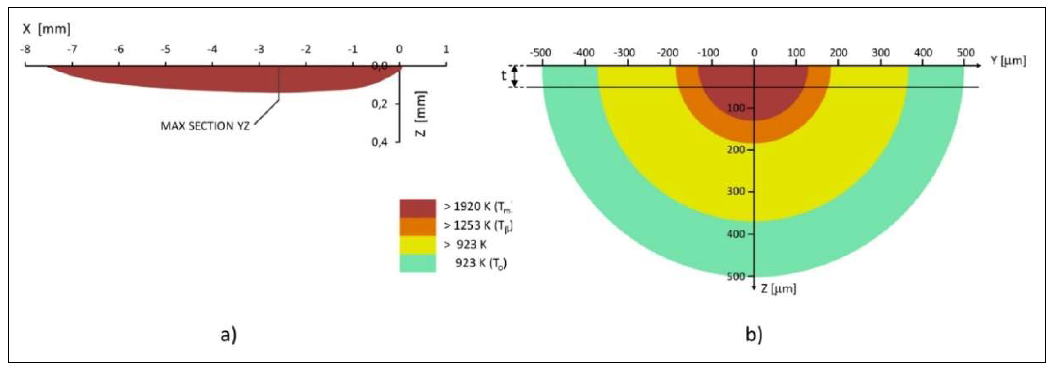
3.1. Theoretical Thermal Analysis of Melt Pool

From data in Table 1, the input energy density calculated by Equation (1) results equal to 20 J/mm3. This value largely exceeds the minimum amount of heat required to melt the unit volume of powder at pre-heating temperature of 650 °C, calculated equal to about 4.4 J/mm3 by Equation (2) for the considered alloy, so verifying the basal condition to sustain the melting process.
Temperature distribution around the coordinate system fixed to the movable point source (that coincides with the origin of the system) has been calculated by Equation (3), fixing the powder bed temperature To and the scanning speed v, and varying the spatial coordinates. In the same equation, the fraction of absorbed beam power η has been set to 0.8, considering the high energy absorptivity evidenced by numerical and experimental investigation on the interaction between electron beam and pure/alloyed Ti powder [42]. The thermo-physical properties of Ti-6Al-4V (ρ, Cp, λ, α) necessary to use Equation (3), have been calculated by polynomial functions of powder bed temperature To [37,43].
Figure 6 represents the results of temperature distribution calculation for powder bed temperature To = 650 °C (as specified previously), power beam P = 900 W and scanning speed along the x axis v = 4.5 m/s (Table 1). Figure 6a shows the melt pool shape as the region of the longitudinal plane xz where temperature exceeds the Ti-6Al-4V melting point (1920 K).
Because of the high electron beam scanning speed, the temperature contours are elongated behind the heat source and compressed in front of the beam. This characteristic of the thermal distribution is clearly reflected on the shape of the melt pool, whose maximum depth is located at a distance of 2.6 mm behind the heat source. Due to the concentration of the thermal source on the origin of the reference system, the highest temperatures are reached in the plane xz. If the beam power is increased, the depth of the pool will also increase. At fast speed and high power, the melt pool becomes narrower and straighter. Consequently, the beam scan spacing must decrease to avoid critical condition of insufficient overlapping such as in Figure 2b (below) and guarantee uniform melting through the whole thickness of the powder layer.
Although the melt pools are highly elongated in the longitudinal section, the transverse sections still show highly localized hemisphere shapes, due to the point heat source modelling. Figure 6b shows the thermal distribution on the transverse plane yx corresponding to the maximum melt pool depth dmp (x = −2.6, dmp = 130 μm), which as highlighted in the same figure, exceeds twice the layer thickness to a limited extent (dmp/t = 2.6), satisfying the well-built condition previously introduced (Section 2.1); according to this thermal distribution, the powder bed begins to heat up to temperatures above To starting from a depth of about 370 μm, and the β-transus condition occurs at a depth of about 180 μm.
As a further result related to the melt pool shape obtained by thermal analysis, the ratio between overlapping depth and layer thickness, calculated for beam power, scanning speed, and scan spacing in Table 1, is dov/t = 1.66, evidencing a well-balanced setting of process parameters.
As regards the overall effect of the coupling between the characteristics of the analyzed thermal field and the reiteration of the fusion process by superposition of the layers, on the structure and properties of the built products, some considerations can be outlined.
Both the melt pool depth and the overlapping efficiency conditions previously introduced (Section 2.1) result satisfied; therefore, excessive layers re-melting during scanning process is avoided for what concerns both cases of adjacent scan lines, on the same layer, and of layers superimposed by deposition cycles. As a consequence, the fine microstructure found by metallographic investigations (Section 3.3) is obtained, which give high strength to the processed material, as confirmed by mechanical characterization (Section 3.4).
Another aspect of the same question is related to thermal losses and their effects. Loss of heat due to thermal conduction has to be distinguished between thermal loss during the local interaction beam–powder and thermal loss until the beam returns to the same point at the adjacent line during scanning. A critical scanning speed above which local thermal loss are negligible and instead heat loss during scanning become prevalent, can be estimated as 8·rb·α/dtd2, where rb is the beam radius (rb = 100 μm from machine specifications), dtd is the thermal diffusion depth, that can be approximated by three times the layer thickness t [40]. Being this threshold value ~0.2 m/s in the present case, therefore well below the set scanning speed (4.5 m/s), heat loss during beam–powder interaction is negligible, letting it emerge heat loss between adjacent scanned lines, during return time of the beam. As a consequence, a decrease of the necessary line energy occurs, due to the fact that more and more heat from previous lines is still available for melting. Furthermore, the substrate of solid material acts as a heat sink; as a consequence, conduction heat loss through the substrate decreases progressively with the deposition of layers, and the peak temperature for the upper layers increases.
The superimposition of both these effects can determine a potential condition of overheating and evaporation. Alloy vapors produced during melting could be one of the causes of the porosity and voids observed during internal inspection of the samples (Section 3.2). Overheating can be also the cause of the loss of aluminium measured by XRF spectrophotometry (Section 2.2), attributable to Al volatility at the temperatures reached in the fusion bath, and which could be a detrimental factor in terms of strength properties. This weakening effect turns out to be negligible here, as evidenced by the good results obtained in terms of material resistance, even at high operating temperatures (Section 3.4).

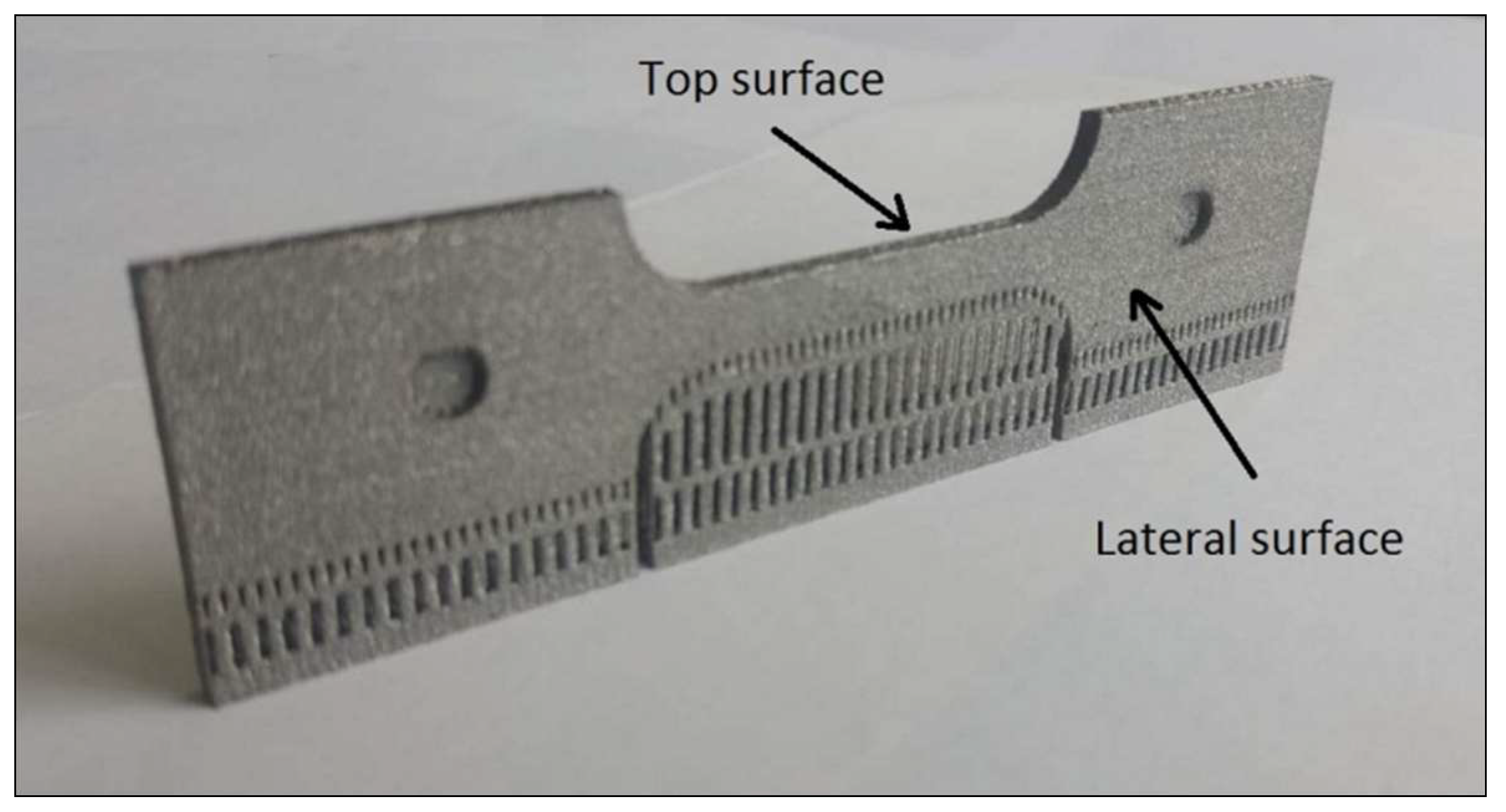
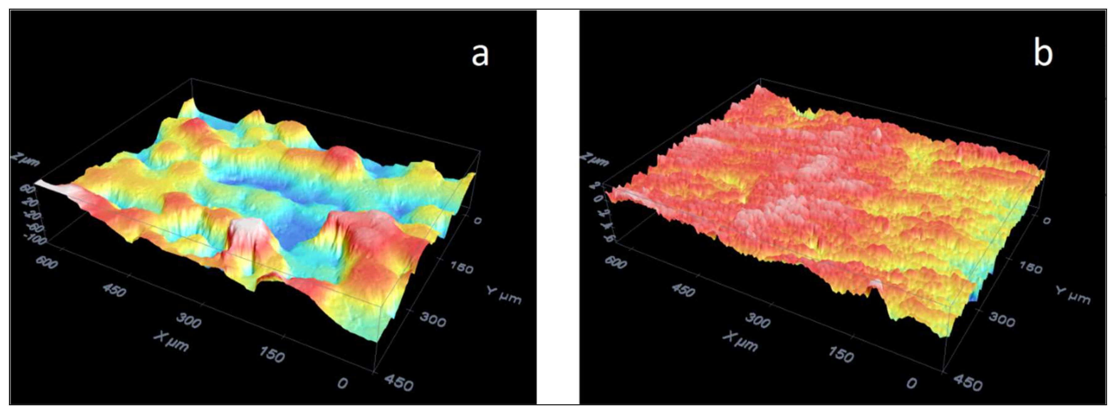
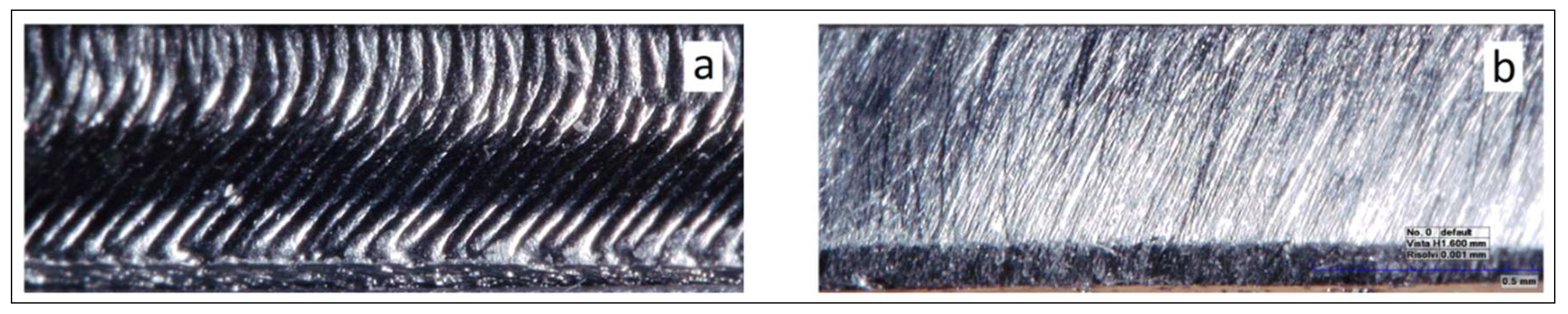
3.2. Surface and Internal Inspections

The inspection of specimens’ external surfaces was carried out by confocal microscopy, in order to produce the 3D reconstructions of the surface morphology and evaluate roughness. Some representative results are given in Figure 7, where as-built smoothed specimens are compared. In the first case (Figure 7a) the 3D reconstruction shows the lateral surface characterized by some voids attributable to lack of powder grains, which determine a high value of the average roughness (Ra = 23 μm). Conversely, the lateral surfaces smoothed by manual grinding or by machining (Figure 7b) are more homogeneous and the average roughness is much smaller (Ra = 0.76 μm).
Surface and internal defects may affect mechanical strength and ductility. The presence of surface defects related to roughness can be solved by removing the damaged external stratum. In particular the as-built specimens show, on their top surface, a longitudinal groove, deep about 0.5 mm and crossed by parallel ridges (Figure 8a). Particular care was taken in eliminating this groove and smoothing the top surface and its edge (Figure 8b).
It is worth noting that on machined specimens surface defects are absent and roughness is very low. In [44] layers 1 mm thick were removed by some milling passes from massive flat specimens (7 mm thick): by this way a ductility equal to 18% was obtained in tensile test.
Regarding internal defects, some porosity and voids were already observed in Reference [45]. Such kind of defect is common in additive manufacturing products: voids with regular spherical shape can be ascribed to incomplete melting of powder particles [18], to gas trapped between particles during the atomization process of powder, to pores formation in molten bath by the shielding gas or to alloy vapors produced during melting [30,45]. Figure 9 shows a spherical void observed on a specimen cross section: it is easy to recognize that its size is in the range of powder particles diameter. Instead the HIP-treated specimens are almost all free of pores, voids, and other damages, both in the bulk and on external surfaces.

3.3. Metallographic Investigation

As known titanium solidifies in the β phase (body centered cubic lattice), that remains stable above the β-transus temperature, equal to about 980 °C for Ti-6Al-4V, while the α phase (hexagonal lattice) is stable at lower temperature. The β → α allotropic transformation is conditioned by the presence of the two main alloying elements: aluminium (α-stabilizer) and vanadium (β-stabilizer). A variety of transformation and microstructures with different combinations of properties can be achieved in this alloy through different heat treatments, according to cooling rate, thus permitting the obtainment of the best mechanical behavior for various applications.
Due to the adopted thermal and/or thermo-mechanical processing route, the Ti-6Al-4V alloy shows basically three different microstructures at room temperature: fully lamellar, fully equiaxed α grains and bi-model (duplex) that contains equiaxed primary α grains in a lamellar matrix [46]. Previous research demonstrated that lamellar microstructure exhibits lower strength, lower ductility, and better fatigue propagation resistance compared with equiaxed microstructure [47]. In fact, equiaxed microstructure provides better fatigue initiation resistance but poorer propagation resistance than the lamellar one [48]. The bimodal microstructure, characterized by α grains surrounded by colonies of α-β lamellas, can be observed after thermal treating below the β-transus temperature followed by cooling at sufficiently high rate to avoid the formation of only the α phase [46]; the bimodal microstructure has excellent fatigue properties, because the high resistance to crack initiation of the equiaxed microstructure (greater than the basket weave one where lamellas act as sites for crack nucleation) is well balanced with the lamellas ability to delay crack propagation. For this reason, the bimodal microstructure shows a very good behavior in high cycle fatigue [49].
In thermal treatments at temperature within the β region, cooling rate is the most important parameter that determines the final morphology of the α phase at room temperature: furnace cooling led to the formation of fully lamellar α-β microstructure; air cooling results in α Widmastatten microstructure, classified also as “basket weave”, which consists of α platelets with an inter-platelets β phase. This microstructure becomes thinner at the increasing of cooling rate [50]. The β → α transformation begins with α nucleation at β grain boundaries. Due to the different solubility, aluminium diffuses into α and at the same time vanadium is expelled from α. Therefore, cooling rate has significant effect on microstructure, because the β → α transformation is controlled by diffusion.
Water quenching gives rise to the diffusionless martensitic transformation of β into the so called α′ martensite. The extremely fast speed of transformation (above 410 °C/s [51]) makes martensite able to grow without thermal activation, consequently it inherits the same composition of the prior β phase. Indeed, the cooperative motion of atoms, through a shear type process, results in a microscopically homogeneous transformation of the β body centered cubic lattice into the α hexagonal lattice. This phase has an acicular microstructure like ferrous martensite, but otherwise titanium martensite is neither significantly stronger nor more brittle [48] than its parent phase. So, hardening of titanium by quenching is only moderate. In any case mechanical properties can be optimized by successive annealing treatments [52].
Micrographs in Figure 10 were taken on the cross section of our specimen (z-y plane), that contains the growing direction (z axis). The deposited powder layers, interspaced of about 50 μm, are well delineated by the boundary of the prior β grains developed during solidification (Figure 10a); as already observed in [25], microstructure is of the basket weave type (Figure 10b). It is characterized by α platelets (light) with an inter-platelets β phase (dark) and took place during the cooling stage inside the vacuum chamber. Due to the extension of the deposition plane and to the heating caused by the layers overlapping, cooling condition are not so severe to led to a martensitic microstructure. Unlike EB-PBF, L-PBF gives rise to more severe cooling and consequently to the formation of the α′ martensite [53].
Aluminium and vanadium have different behavior, because Al preferentially enters into α, while V likely into β. Consequently, as pointed out by various authors [54,55], in the basket weave microstructure it can be detected the presence in little amount of the retained β phase at the α platelets boundaries. In the SEM micrograph shown in Figure 11 dark and light regions are the α and β phases respectively.
The influence of microstructure on tensile properties was studied in Reference [56] for the basket weave morphology, showing that yield strength and ductility depends on α lath thickness; they both decrease when it increases. Instead α lath thickness has no relevant influence on the ultimate tensile strength. This can be explained considering that a decrease in α lath thickness reduces the effective slip length and therefore increases the yield strength.
The specimens treated by HIP are characterized by the absence of porosity both on the external surface and on the cross sections (z-y). In these specimens, metallographic observation highlight significant coarsening of the α platelets, that look stockier than ones observed in non-HIPped specimens; the β phase remains present in the space between platelets (Figure 12).
The presence of the α phase can be clearly detected by the XRD pattern in Figure 13, where peaks are labelled according to ICDD PDF 04-002-8708. In the as-built specimens only little evidence of the β phase was found: in particular the hump at the base of the α (101) peak can be ascribed to the β (110) line. The rather weak reflection of the β phase is due to its relatively low volume fraction and it is a feature of the basket weave microstructure where β is present only between two α platelets. More evidence of the β (110) line can be found in the diffraction pattern of a HIPped specimen.

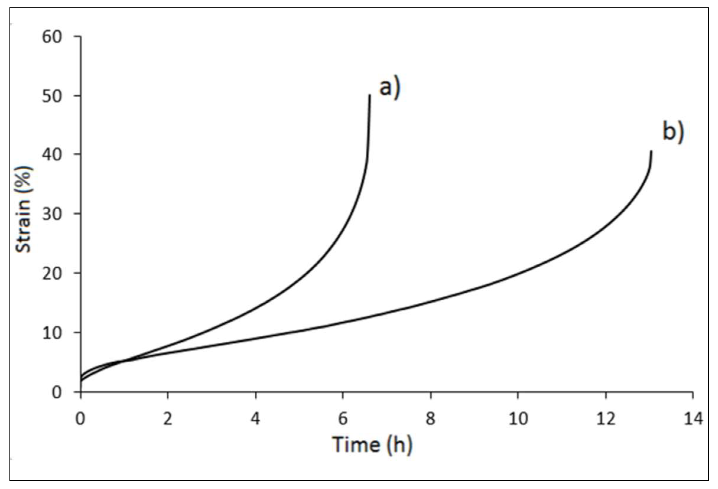
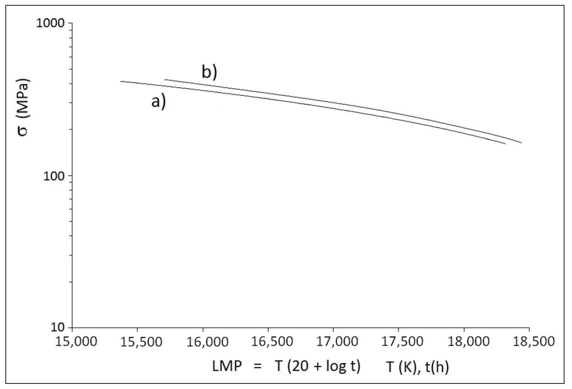
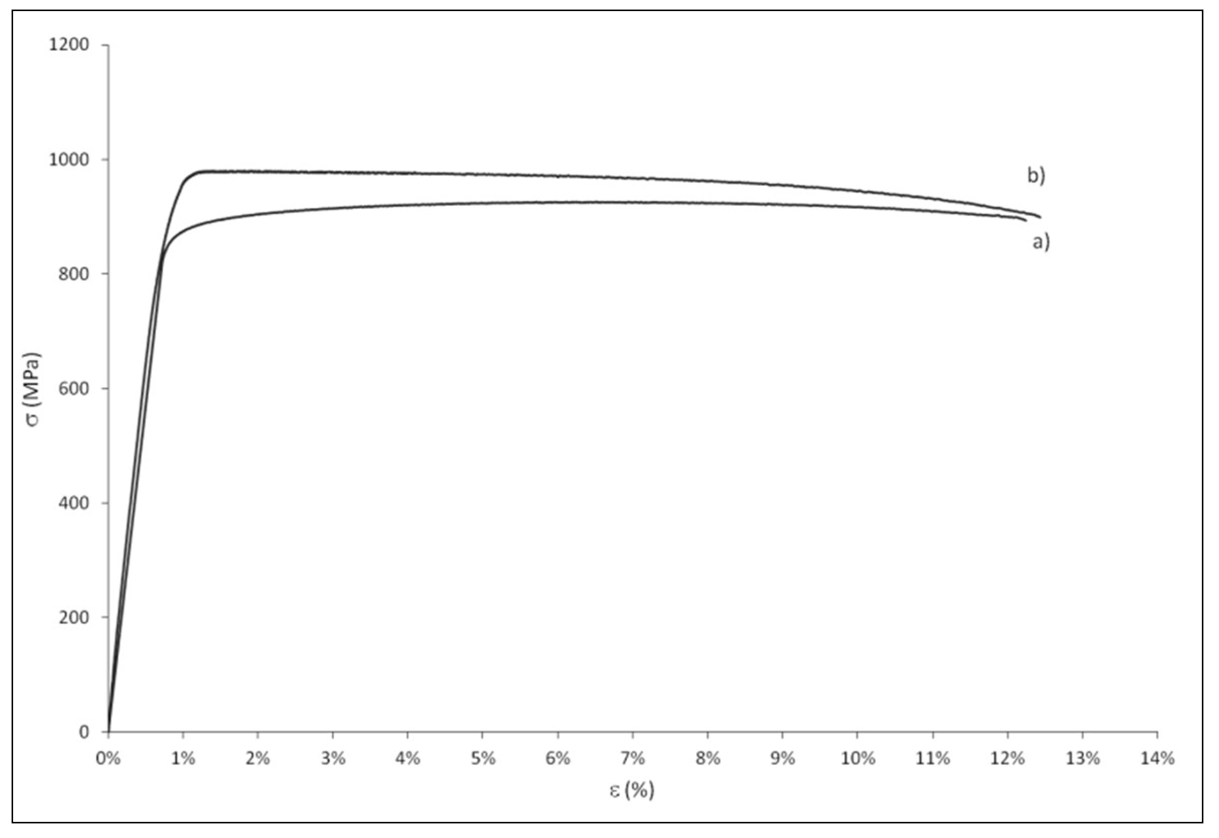
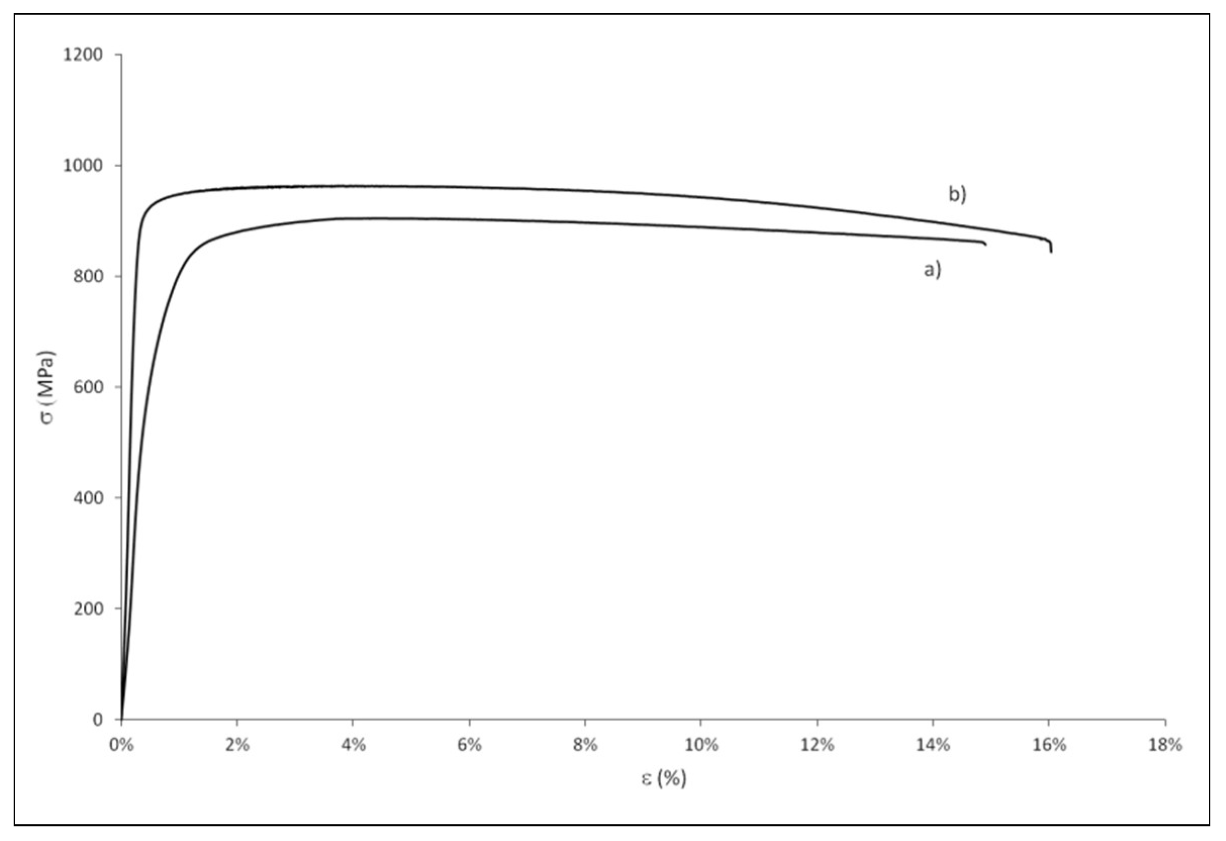
3.4. Mechanical Properties

At room temperature the 0.2% offset yield strength is about 740 MPa, the ultimate strength 800 MPa, elongation is below 10% and necking negligible. The experimental points in Figure 14 are representative of mean values: the results variability was in the range of 15% for ductility (ε) and 7% for yield strength (σy) and ultimate tensile strength (σUTS). At the increasing of test temperature, ductility increases reaching a value equal to 30% at 800 °C, while mechanical strength decreases maintaining appreciable values: at 600 °C yield strength and ultimate tensile strength are respectively equal to 340 and 390 (MPa). These performances are typical of Ti-6Al-4V lamellar microstructure specimens obtained by EB-PBF, certainly lower than the ones exhibited by forged products.
A very fine microstructure, as the basket wave one observed by us, determines high resistance to deformation: as a matter of fact, a refinement of the α lath thickness reduces the effective dislocation slip length and therefore increases the yield strength, even if without appreciable effects on the ultimate tensile strength. The tensile properties experimented with our fully lamellar specimens are certainly lower than the ones exhibited by forged products with a less fine microstructure. The reasons for this behavior has to be searched in the surface status and also in the presence of bulk defects, which are both cause of premature ruptures.
Regarding the effect of smoothing, we found it very effective in delaying final fracture and so enhancing mechanical properties. Two typical stress–strain curves obtained at room temperature for specimen type A are given in Figure 15. The smoothed specimen shows greater mechanical strength and slightly higher ductility than the as-built one. In both cases the yield strength results about 90% of the ultimate strength and necking is negligible.
Fracture surfaces have predominantly a ductile appearance, however, in some cases there are easily recognizable spherical voids crossed by cracks and surrounded by planes of direct separation (Figure 16). The presence of these defects explains why mechanical behavior of EB-PBF products is generally poorer than that of Ti-6Al-4V forged products with the same basket weave microstructure [49,57]. As demonstrated in Reference [58], porosity is the main factor controlling tensile properties and microstructure becomes important for cases where defects are close to zero.
The best mechanical behavior of smoothed specimens is confirmed also by creep test, as shown by the strain–time curves for as-built and smoothed specimens A given in Figure 17.
Regarding creep behavior, we observed that it is very sensitive to test temperature; the strain–time curves undergo a remarkable increment of the stationary creep rate at the increasing of temperature, as a consequence of the high values of the activation energy (calculated around 300 kJ/mol in [59]). In all cases smoothing delayed creep rupture: the results of our creep surveys are plotted in Figure 18 in the form of the Larson Miller diagram (mean values), being σ (MPa) the test load and LMP = T (C + logt) the Larson Miller Parameter, with T(K) test temperature, t(h) rupture time and C a characteristic constant, assumed equal to 20 according to a literature datum [60].
Comparing Figure 19 with the previous Figure 15, both in the as-built and after surface finishing conditions the massive specimens type B show better elongation (over 12%) than the specimens type A (around 10%).
In accordance with literature data for specimens having the longitudinal section coplanar to the process plane [22,45,61], the strength after hot isostatic pressing is slightly decreased, while the elongation is increased (Figure 20). These results confirm the known effects on strength and ductility attributed to the HIP process [62,63]. Such as any heat treatment at high temperature for a significantly long time, hot pressing coarsens the microstructure (with particular regard to α phase, as evidenced by metallographic investigation reported previously), and to this is attributed the reduction of strength properties. On the other hand, reduction of porosity and defects removal favour the increase of ductility: according to the results obtained, the HIP process allows to improve elongation up to 15%; moreover, machining reduces roughness and enhances further ductility that reaches a value equal to 16% (Figure 20).

4. Conclusions

The aim of our research was to improve tensile and creep behaviour of Ti-6Al-4V alloy specimens produced by Electron Beam Powder Bed Fusion additive technology, investigating the potential of the combined effects of different type of surface finishing (smoothing, machining) and the densification of bulk volume through hot isostatic pressing. As it turned out, the fabrication process strongly influences microstructure features and mechanical properties. The main conclusions can be summarized as follows:
(a)
Thermal analysis results allowed to validate the process parameter setting, achieving a well-balanced conditions for overlapping of the molten zones of two adjacent depositions, without exceeding in overheating.
(b)
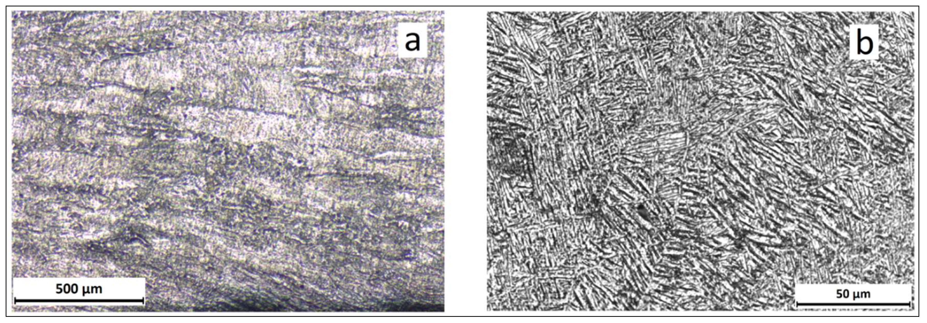
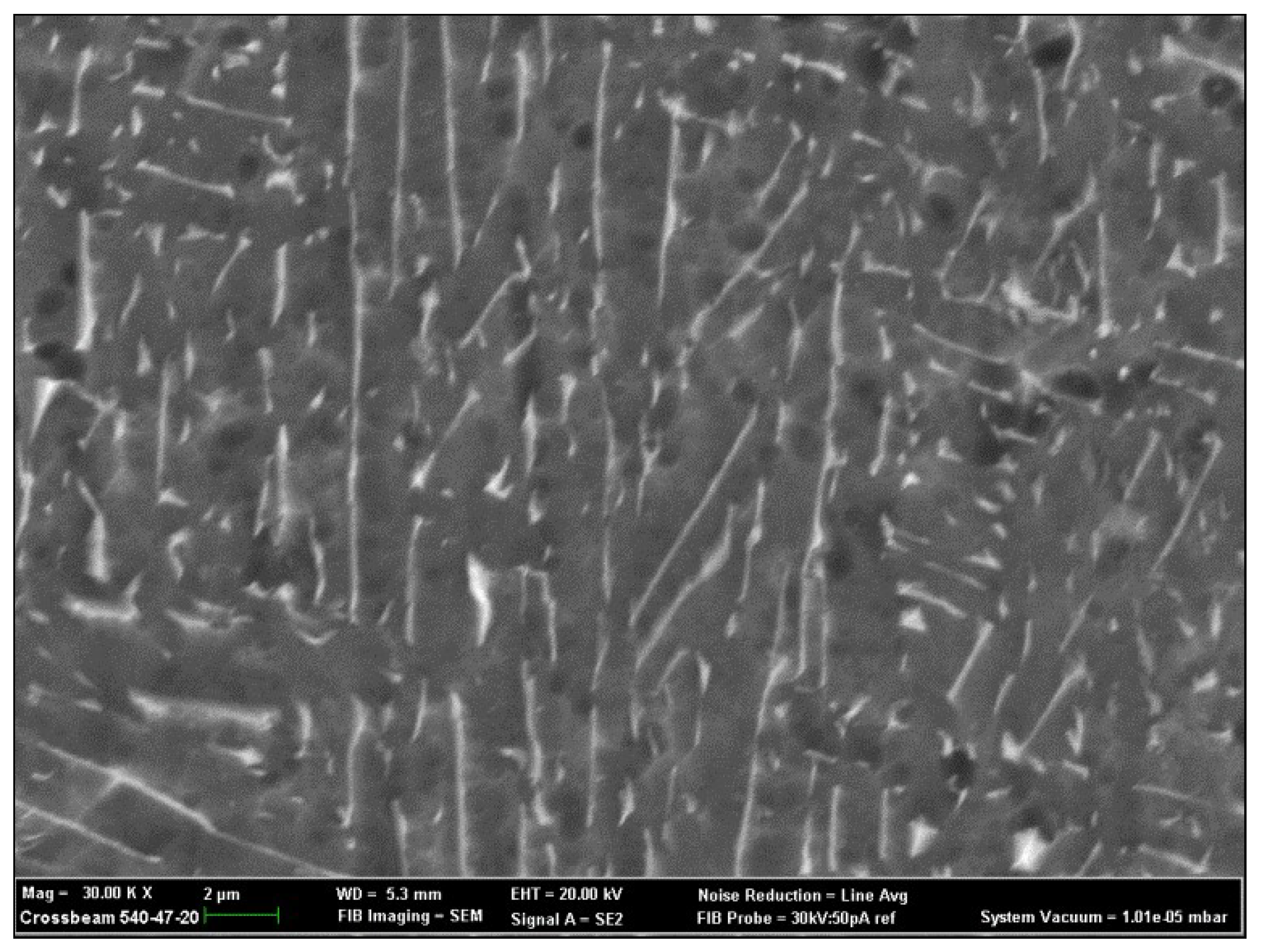
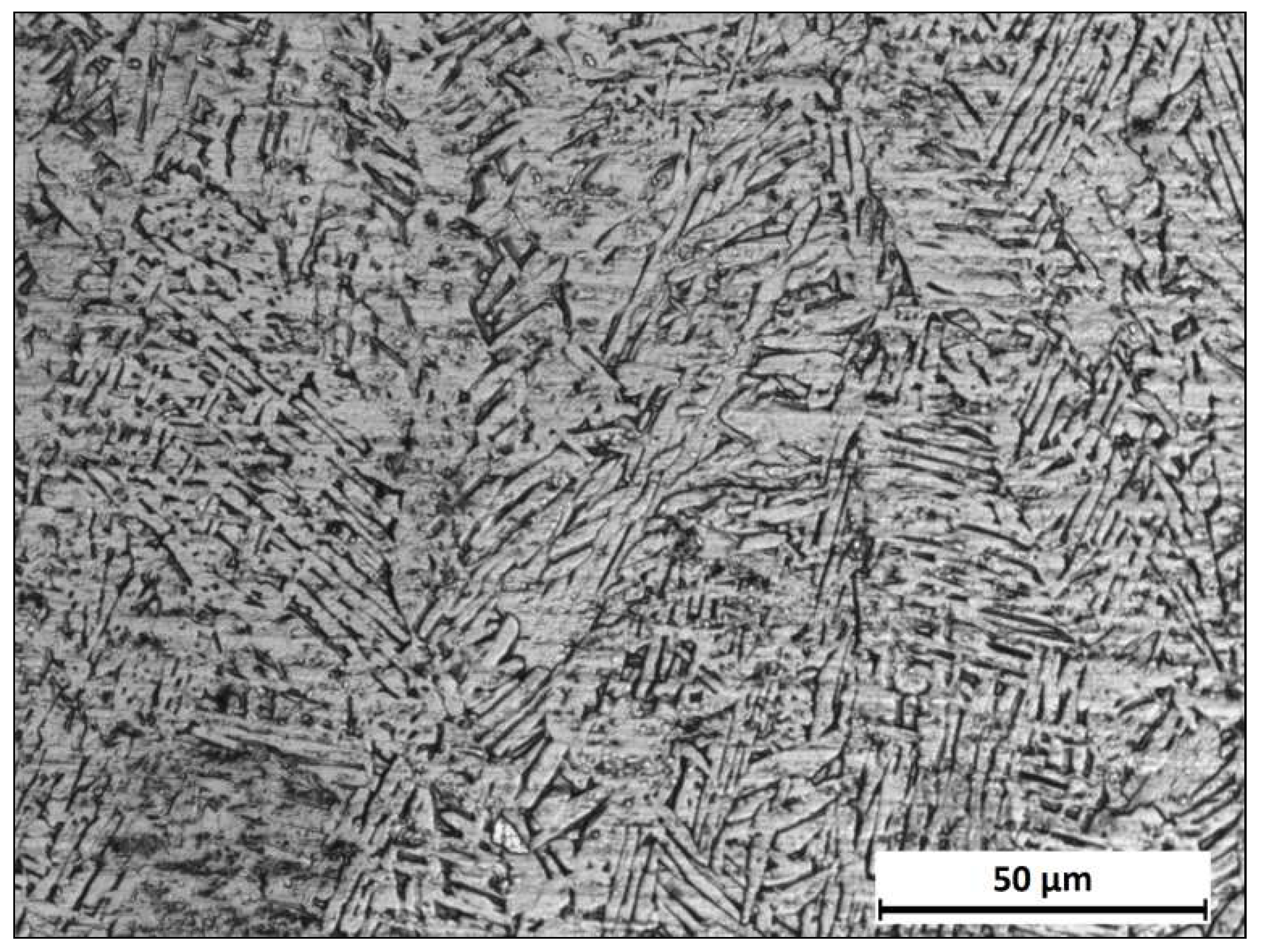
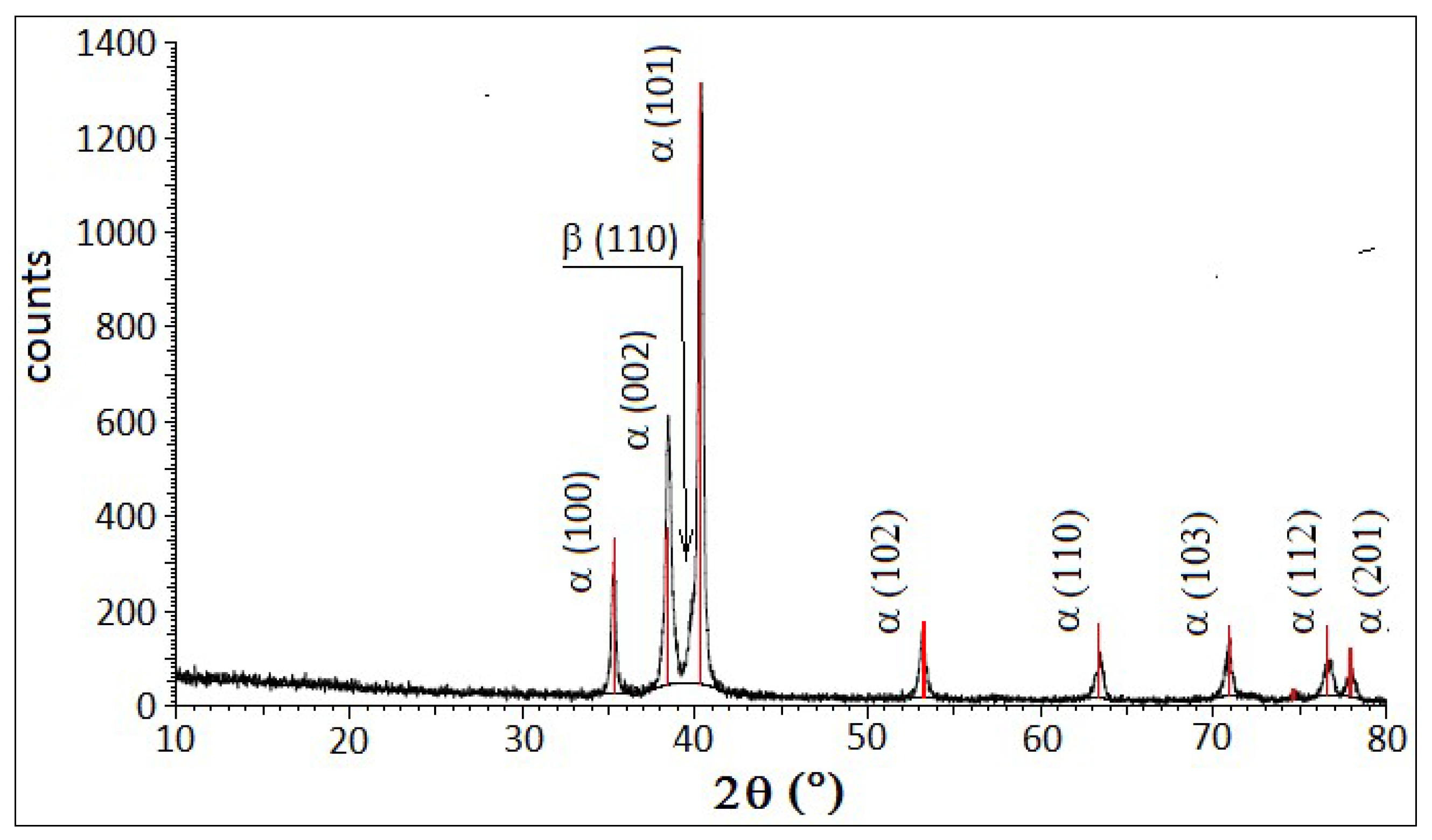
Metallographic observation highlighted a basket weave microstructure with fine α platelets surrounded by the inter-platelets β phase. XRD investigation confirmed the presence of the α phase with low content of the β phase.
(c)
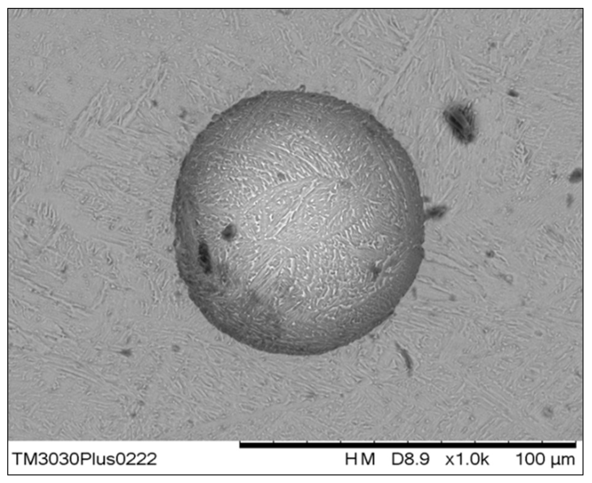
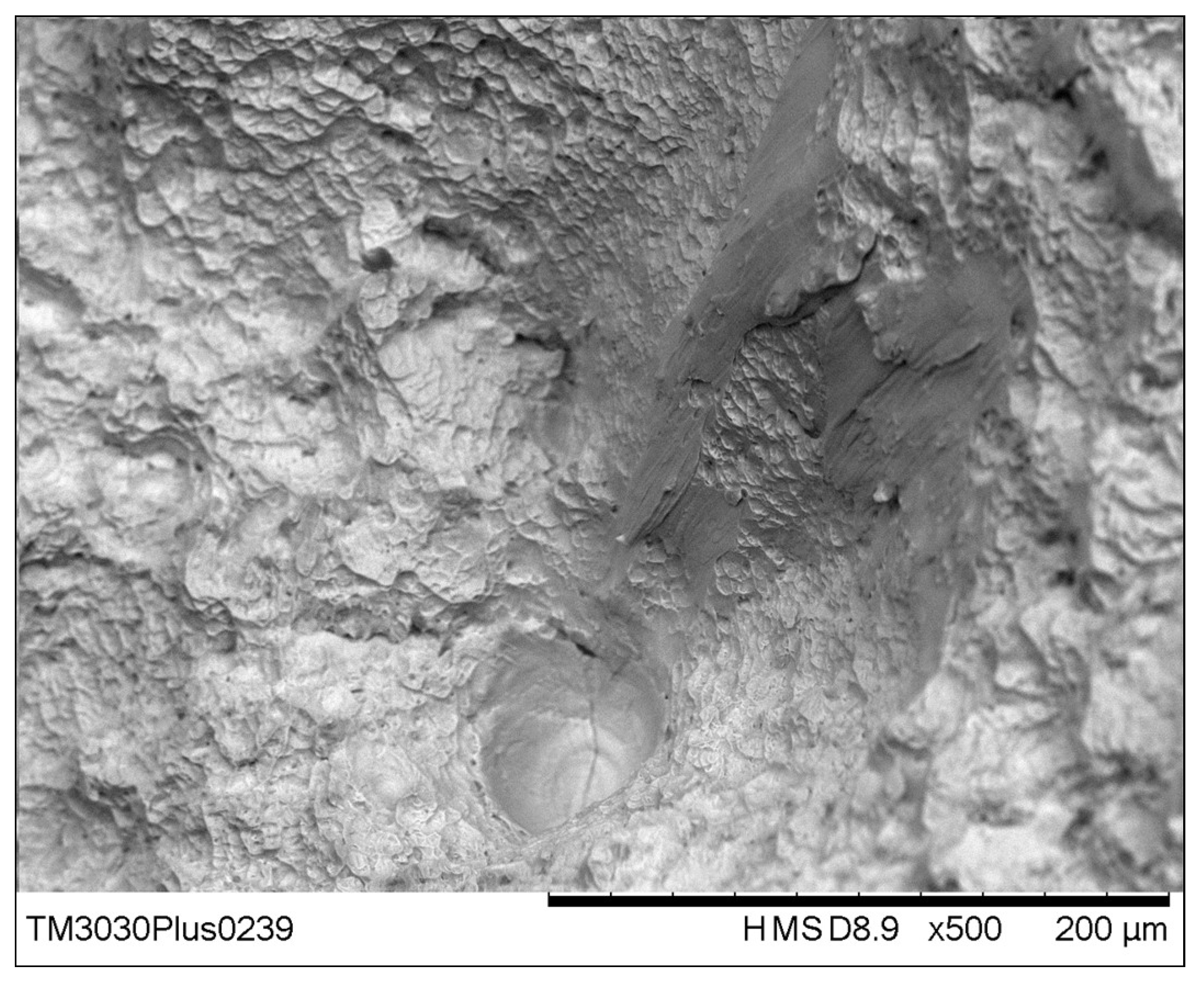
As typical in manufactured parts produced by melting of a powder bed, in our EB-PBF specimens we observed some surface defects and internal voids. The improvement of surface conditions gets better tensile and creep behavior; for this purpose, machining is preferable to smoothing by manual grinding.
(d)
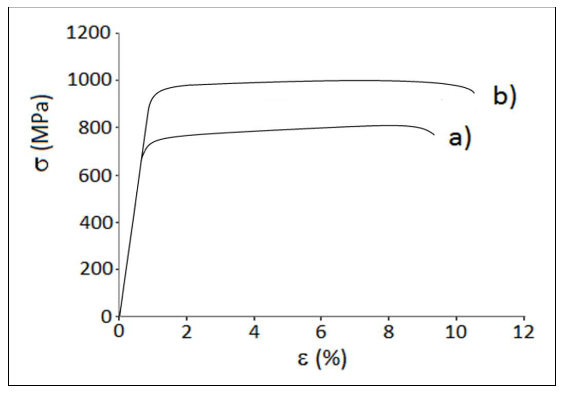
A good tensile behavior was obtained treating specimens by hot isostatic pressing that allows to relieve stresses and reduces largely bulk defects detrimental to mechanical properties. The best ductility was obtained by machining the specimen surface after HIPping.

Author Contributions

Conceptualization, F.G., E.G., A.S.; methodology, E.G., A.S..; investigation F.G., P.A., A.S.; resources, F.G., E.G., A.S.; data curation, F.G., P.A., A.S.; writing—original draft preparation, F.G., A.S.; visualization, F.G., P.A., A.S.; supervision, E.G., A.S; funding acquisition, F.G., E.G.

Funding

This research was partly funded by the University of Catania within the project “Piano della Ricerca Dipartimentale 2016-2018” of the Department of Civil Engineering and Architecture.

Acknowledgments

The authors wish to thank the company MT Ortho (Aci S. Antonio CT, Italy) and in particular Eng. Simone Di Bella, to have kindly made the specimens, for providing all the information on the process parameters and for the useful suggestions.

Conflicts of Interest

The authors declare no conflict of interest.

References

  1. Donachie, M.J., Jr. Titanium. A Technical Guide, 2nd ed.; ASM International, Materials Park: Novelty, OH, USA, 2000. [Google Scholar]
  2. Elias, C.N.; Lima, J.H.C.; Valiev, R.; Meyers, M.A. Biomedical applications of titanium and its alloys. JOM 2008, 60, 46–49. [Google Scholar] [CrossRef]
  3. Gloria, A.; Montanari, R.; Richetta, M.; Varone, A. Alloys for aeronautic applications: State of the art and perspectives. Metals 2019, 9, 662. [Google Scholar] [CrossRef]
  4. Lu, M.; Zhou, J.; Lin, J.; Gu, Y.; Han, J.; Zhao, D. Study on Ti-6Al-4V alloy machining applying the non-resonant three-dimensional elliptical vibration cutting. Micromachines 2017, 8, 306. [Google Scholar] [CrossRef] [PubMed]
  5. Bahnini, I.; Rivette, M.; Rechia, A.; Siadat, A.; Elmesbahi, A. Additive manufacturing technology: The status, applications, and prospects. Int. J. Adv. Manuf. Technol. 2018, 97, 147–161. [Google Scholar] [CrossRef]
  6. Tan, X.P.; Kok, Y.H.; Tan, Y.J.; Descoins, M.; Mangelinck, D.; Tor, S.B.; Leong, K.F.; Chua, C.K. Graded microstructure and mechanical properties of additive manufactured Ti-6Al-4V via electron beam melting. Acta Mater. 2015, 97, 1–16. [Google Scholar] [CrossRef]
  7. Mostafaei, A.; Toman, J.; Stevens, E.L.; Hughes, E.T.; Krimer, Y.L.; Chmielus, M. Microstructural evolution and mechanical properties of differently heat-treated binder jet printed samples from gas-and water-atomized alloy 625 powders. Acta Mater. 2017, 124, 280–289. [Google Scholar] [CrossRef]
  8. Gibson, I.; Rosen, D.; Strucker, B. Additive Manufacturing Technologies: 3D Printing, Rapid Prototyping, and Direct Digital Manufacturing; Springer: Berlin, Germany; New York, NY, USA, 2015. [Google Scholar]
  9. Frazier, W.J. Metal additive manufacturing: A review. Mater. Eng. Perform. 2014, 23, 1917–1928. [Google Scholar] [CrossRef]
  10. Herzog, D.; Seyda, V.; Wycisk, E.; Emmelmann, C. Additive manufacturing of metals. Acta Mater. 2016, 117, 371–392. [Google Scholar] [CrossRef]
  11. Salsi, E.; Chiumenti, M.; Cervera, M. Modeling of microstructure evolution of Ti6Al4V for additive manufacturing. Metals 2018, 8, 633. [Google Scholar] [CrossRef]
  12. Fousová, M.; Vojtěch, D.; Doubrava, K.; Daniel, M.; Lin, C.-F. Influence of inherent surface and internal defects on mechanical properties of additively manufactured Ti6Al4V alloy: Comparison between selective laser melting and electron beam melting. Materials 2018, 11, 537. [Google Scholar]
  13. Rafi, H.K.; Karthik, N.V.; Gong, H.; Starr, T.L.; Stucker, B.E. Microstructures and mechanical properties of Ti6Al4V parts fabricated by selective laser melting and electron beam melting. J. Mater. Eng. Perform. 2013, 22, 3872–3883. [Google Scholar] [CrossRef]
  14. Wysocki, B.; Maj, P.; Sitek, R.; Buhagiar, J.; Kurzydłowski, K.J.; Swieszkowski, W. Laser and electron beam additive manufacturing methods of fabricating titanium bone implants. Appl. Sci. 2017, 7, 657. [Google Scholar] [CrossRef]
  15. Svensson, M.; Ackelid, U. Influence of interstitial elements on the mechanical properties of Ti-6Al-4V produced with electron beam melting. In Proceedings of the Materials Science and Technology Conference MS&T’11, Columbus, OH, USA, 16–20 October 2011. [Google Scholar]
  16. Murr, L.E.; Gaytan, S.M.; Ramirez, D.A.; Martinez, E.; Hernandez, J.; Amato, K.N.; Shindo, P.W.; Medina, F.R.; Wicker, R. Metal fabrication by additive manufacturing using laser and electron beam melting technologies. J. Mater. Sci. Technol. 2012, 28, 1–14. [Google Scholar] [CrossRef]
  17. Ahmed, M.; Abdo, B.M.; Darwish, S.; Moiduddin, K.; Pervaiz, S.; Alahmari, A.M.; Naveed, M. Electron beam melting of titanium alloy and surface finish improvement through rotary ultrasonic machining. Int. J. Adv. Manuf. Technol. 2017, 92, 3349–3361. [Google Scholar] [CrossRef]
  18. Qiu, C.; Adkins, N.J.E.; Attallah, M.M. Microstructure and tensile properties of selectively laser-melted and of HIPed laser-melted Ti-6Al-4V. Mater. Sci. Eng. A 2013, 578, 230–239. [Google Scholar] [CrossRef]
  19. Popov, V.; Katz-Demyanetz, A.; Garkun, A.; Muller, G.; Strokin, E.; Rosenson, H. Effect of hot isostatic pressure treatment on the electron-beam melted Ti-6Al-4V specimens. Proced. Manuf. 2018, 21, 125–132. [Google Scholar] [CrossRef]
  20. Al-Bermani, S.S.; Blackmore, M.L.; Zhang, W.; Todd, I. The origin of microstructural diversity, texture, and mechanical properties in electron beam melted Ti-6Al-4V. Metall. Mater. Trans. 2010, 41A, 3422–3434. [Google Scholar] [CrossRef]
  21. Maizza, G.; Caporale, A.; Polley, C.; Seitz, H. Micro-macro relationship between microstructure, porosity, mechanical properties, and build mode parameters of a selective-electron-beam-melted Ti-6Al-4V alloy. Metals 2019, 9, 786. [Google Scholar] [CrossRef]
  22. Lewandowski, J.J.; Seifi, M. Metal additive manufacturing: A review of mechanical properties. Annu. Rev. Mater. Res. 2016, 46, 151–186. [Google Scholar] [CrossRef]
  23. Kok, Y.; Tan, X.P.; Wang, P.; Nai, M.L.S.; Loh, N.H.; Liu, E.; Tor, S.B. Anisotropy and heterogeneity of microstructure and mechanical properties in metal additive manufacturing: A critical review. Mater. Des. 2018, 139, 565–586. [Google Scholar] [CrossRef]
  24. Liu, S.; Shin, Y.C. Additive manufacturing of Ti6Al4V alloy: A review. Mater. Des. 2019, 164, 107552. [Google Scholar] [CrossRef]
  25. Aliprandi, P.; Giudice, F.; Guglielmino, E.; La Rosa, G.; Sili, A. Creep behavior of Ti-6Al-4V alloy specimens produced by Electron Beam Melting. Metall. Ital. 2019, 6, 18–23. [Google Scholar]
  26. Mirone, G.; Barbagallo, R.; Corallo, D.; Di Bella, S. Static and dynamic response of titanium alloy produced by electron beam melting. Proced. Struct. Integr. 2016, 2, 2355–2366. [Google Scholar] [CrossRef] [Green Version]
  27. Kalinyuk, A.N.; Trigub, N.P.; Zamkov, V.N.; Ivasishin, O.M.; Markovsky, P.E.; Teliovich, R.V.; Semiatin, S.L. Microstructure, texture, and mechanical properties of electron-beam melted Ti-6Al-4V. Mater. Sci. Eng. A 2003, 346, 178–188. [Google Scholar] [CrossRef]
  28. Zhang, L.-C.; Liu, Y.; Li, S.; Hao, Y. Additive manufacturing of titanium alloys by electron beam melting: A review. Adv. Eng. Mater. 2018, 20, 1700842. [Google Scholar] [CrossRef]
  29. Arcam A.B. Welcome to Manufacturing Unbound. Available online: www.arcam.com (accessed on 16 May 2019).
  30. Gaytan, S.M.; Murr, L.E.; Medina, F.; Martinez, E.; Lopez, M.I.; Wicker, R.B. Advanced metal powder based manufacturing of complex components by electron beam melting. Mater. Technol. 2009, 24, 180–190. [Google Scholar] [CrossRef]
  31. Gong, X.; Anderson, T.; Chou, K. Review on powder-based electron beam additive manufacturing technology. Manuf. Rev. 2014, 1, 1–12. [Google Scholar] [CrossRef]
  32. Mireles, J.; Terrazas, C.; Gaytan, S.M.; Roberson, D.A.; Wicker, R.B. Closed-loop automatic feedback control in electron beam melting. Int. J. Adv. Manuf. Technol. 2015, 78, 1193–1199. [Google Scholar] [CrossRef]
  33. Thijs, L.; Verhaeghe, F.; Craeghs, T.; Van Humbeeck, J.; Kruth, J.P. A study of the microstructural evolution during selective laser melting of Ti-6Al-4V. Acta Mater. 2010, 58, 3303–3312. [Google Scholar] [CrossRef]
  34. Scharowsky, T.; Bauereiß, A.; Korner, C. Influence of the hatching strategy on consolidation during selective electron beam melting of Ti-6Al-4V. Int. J. Adv. Manuf. Technol. 2017, 92, 2809–2818. [Google Scholar] [CrossRef]
  35. Thomas, M.; Baxter, G.J.; Todd, I. Normalised model-based processing diagrams for additive layer manufacture of engineering alloys. Acta Mater. 2016, 108, 26–35. [Google Scholar] [CrossRef] [Green Version]
  36. DebRoy, T.; Wei, H.L.; Zuback, J.S.; Mukherjee, T.; Elmer, J.W.; Milewski, J.O.; Beese, A.M.; Wilson-Heid, A.; De, A.; Zhang, W. Additive manufacturing of metallic components: Process, structure and properties. Prog. Mater. Sci. 2018, 92, 112–224. [Google Scholar] [CrossRef]
  37. Cline, H.E.; Anthony, T.R. Heat treating and melting material with a scanning laser or electron beam. J. Appl. Phys. 1977, 48, 3895–3900. [Google Scholar] [CrossRef]
  38. Galati, M.; Iuliano, L.A. Literature review of powder-based electron beam melting focusing on numerical simulations. Addit. Manuf. 2018, 19, 1–20. [Google Scholar] [CrossRef]
  39. Bontha, S.; Klingbeil, N.W.; Kobryn, P.A.; Fraser, H.L. Thermal process maps for predicting solidification microstructure in laser fabrication of thin-wall structures. J. Mater. Process. Technol. 2006, 178, 135–142. [Google Scholar] [CrossRef]
  40. Juechter, V.; Scharowsky, T.; Singer, R.F.; Korner, C. Processing window and evaporation phenomena for Ti-6Al-4V produced by selective electron beam melting. Acta Mater. 2014, 76, 252–258. [Google Scholar] [CrossRef]
  41. Safdar, A.; Wei, L.Y.; Snis, A.; Lai, Z. Evaluation of microstructural development in electron beam melted Ti-6Al-4V. Mater. Charact. 2012, 65, 8–15. [Google Scholar] [CrossRef]
  42. Klassen, A.; Bauereiß, A.; Korner, C. Modelling of electron beam absorption in complex geometries. J. Phys. D Appl. Phys. 2014, 47, 065307. [Google Scholar] [CrossRef]
  43. Mills, K.C. Recommended Values of Thermophysical Properties for Selected Commercial Alloys; Woodhead Publishing: Cambridge, UK, 2002. [Google Scholar]
  44. Epasto, G.; Palomba, G.; D’Andrea, D.; Guglielmino, E.; Di Bella, S.; Traina, F. Ti-6Al-4V ELI microlattice structures manufactured by electron beam melting: Effect of unit cell dimensions and morphology on mechanical behaviour. Mater. Sci. Eng. A 2019, 753, 31–41. [Google Scholar] [CrossRef]
  45. Svensson, M.; Ackelid, U. Titanium alloys manufactured with electron beam melting mechanical and chemical properties. In Proceedings of the Materials and Processes for Medical Devices Conference, Minneapolis, MN, USA, 10–12 August 2009. [Google Scholar]
  46. Ding, R.; Guo, Z.X.; Wilson, A. Microstructural evolution of a Ti-6Al-4V alloy during thermomechanical processing. Mater. Sci. Eng. A 2002, 327, 233–245. [Google Scholar] [CrossRef]
  47. Leyens, C.; Peter, M. Titanium and Titanium Alloys: Fundamentals and Applications; Wiley-VCH Verlag: Weinheim, Germany, 2003. [Google Scholar]
  48. Fan, Y.; Tian, W.; Guo, Y.; Sun, Z.; Xu, J. Relationships among the microstructure, mechanical properties, and fatigue behavior in thin Ti6Al4V. Adv. Mater. Sci. Eng. 2016, 2016, 1–9. [Google Scholar] [CrossRef]
  49. Crupi, V.; Epasto, G.; Guglielmino, E.; Squillace, A. Influence of microstructure [alpha + beta and beta] on very high cycle fatigue behavior of Ti-6Al-4V alloy. Int. J. Fatigue 2017, 95, 64–75. [Google Scholar] [CrossRef]
  50. Vrancken, B.; Thijs, L.; Kruth, J.P.; Van Humbeeck, J. Heat treatment of Ti6Al4V produced by Selective Laser Melting: Microstructure and mechanical properties. J. Alloy. Compd. 2012, 541, 177–185. [Google Scholar] [CrossRef] [Green Version]
  51. Ahmed, T.; Rack, H.J. Phase transformation during cooling in α+β titanium alloys. Mater. Sci. Eng. A 1998, 243, 206–211. [Google Scholar] [CrossRef]
  52. Pinke, P.; Réger, M. Heat treatment of the casted Ti6Al4V titanium alloy. Mater. Sci. Technol. 2005, 5, 1–6. [Google Scholar]
  53. Zhao, Z.-Y.; Li, L.; Bai, P.-K.; Jin, Y.; Wu, L.-Y.; Li, J.; Guan, R.-G.; Qu, H.-Q. The heat treatment influence on the microstructure and hardness of TC4 titanium alloy manufactured via selective laser melting. Materials 2019, 11, 1318. [Google Scholar] [CrossRef]
  54. Reda, R.; Hussein, A.-H.; Nofak, A.; EL-Banna, E.-S. Optimizing the mechanical properties of Ti-6Al-4V castings. Int. J. Mech. Prod. Eng. Res. Dev. 2015, 5, 83–104. [Google Scholar]
  55. Liang, Z.; Sun, Z.; Zhang, W.; Wu, S.; Chang, H. The effect of heat treatment on microstructure evolution and tensile properties of selective laser melted Ti6Al4V alloy. J. Alloy. Compd. 2019, 782, 1041–1048. [Google Scholar] [CrossRef]
  56. Galarraga, H.; Warren, R.J.; Ladosa, D.A.; Dehoff, R.R.; Kirkab, M.M.; Nandwana, P. Effects of heat treatments on microstructure and properties of Ti-6Al-4V ELI alloy fabricated by electron beam melting (EBM). Mater. Sci. Eng. A 2017, 685, 417–428. [Google Scholar] [CrossRef] [Green Version]
  57. Benedetti, M.; Fontanari, V. The effect of bi-modal and lamellar microstructures of Ti-6Al-4V on the behaviour of fatigue cracks emanating from edge-notches. Fatigue Fract. Eng. Mater. Struct. 2004, 27, 1073–1089. [Google Scholar] [CrossRef]
  58. Galarraga, H.; Lados, D.A.; Dehoff, R.R.; Kirka, M.M.; Nandwana, P. Effects of the microstructure and porosity on properties of Ti-6Al-4V ELI alloy fabricated by electron beam melting (EBM). Addit. Manuf. 2016, 10, 47–57. [Google Scholar] [CrossRef] [Green Version]
  59. Badea, L.; Surand, M.; Ruau, J.; Viguier, B. Creep behavior of Ti-6Al-4V from 450 °C to 600 °C. UPB Sci. Ser. B 2014, 76, 185–196. [Google Scholar]
  60. Koike, J.; Maruyama, K. Study of primary creep in Ti-6-22-22S alloys. Mater. Sci. Eng. A 1999, 263, 155–159. [Google Scholar] [CrossRef]
  61. Tang, H.P.; Wang, J.; Song, C.N.; Liu, N.; Jia, L.; Elambasseril, J.; Qian, M. Microstructure, mechanical properties, and flatness of SEBM Ti-6Al-4V sheet in as-built and hot isostatically pressed conditions. JOM 2017, 69, 466–471. [Google Scholar] [CrossRef]
  62. Mohammadhosseini, A.; Fraser, D.; Masood, S.H.; Jahedi, M. Microstructure and mechanical properties of Ti-6Al-4V manufactured by electron beam melting process. Mater. Res. Innov. 2013, 17, 106–112. [Google Scholar] [CrossRef]
  63. Eklund, A.; Ahlfors, M.; Bahbou, F.; Wedenstrand, J. Optimizing HIP and printing parameters for EBM Ti-6Al-4V. Key Eng. Mater. 2018, 770, 174–178. [Google Scholar] [CrossRef]
Figure 1. Electron beam powder bed fusion (EB-PBF) machine [29]: (a) Beam generation column; (b) Filament; (c) Lens system; (d) Vacuum chamber; (e) Electron beam; (f) Powder hopper; (g) Rake; (h) Build tank; (i) Start plate.
Metals 09 01207 g001
Figure 2. Electron beam powder bed fusion (EB-PBF) process: (a) Basic scheme of electron beam scanning; (b) Effect of scan spacing on overlapping condition.
Metals 09 01207 g002
Figure 3. Specimens specification: (a) Typology with respect to the process plane; (b) Pattern of scanning line (snake x-y type) [28].
Metals 09 01207 g003
Figure 4. Schematic drawing of specimens for tensile and creep tests (unit: mm).
Metals 09 01207 g004
Figure 5. As printed specimen.
Metals 09 01207 g005
Figure 6. Thermal analysis of melt pool: (a) Melt pool shape in the central longitudinal plane xz; (b) Temperature field of the transverse cross section at the maximum melt pool depth.
Metals 09 01207 g006
Figure 7. 3D surface reconstruction (specimens A): (a) Surface in the as-built condition; (b) Smoothed surface.
Metals 09 01207 g007
Figure 8. Optical macrographs of top surface (specimens A): (a) As-built; (b) Smoothed by manual grinding.
Metals 09 01207 g008
Figure 9. Optical micrograph of a specimen cross section with a spherical void.
Metals 09 01207 g009
Figure 10. Optical micrographs performed on the cross section (specimen A): (a) Low magnification; (b) High magnification.
Metals 09 01207 g010
Figure 11. Scanning electron microscopy (SEM) micrograph taken on specimen A cross section.
Metals 09 01207 g011
Figure 12. Optical micrographs of specimen B cross section after hot isostatic pressing (HIP).
Metals 09 01207 g012
Figure 13. X-ray diffraction (XRD) pattern of an as-built specimen; the red lines indicates the characteristic diffraction peaks of the α phase.
Metals 09 01207 g013
Figure 14. Ultimate tensile strength, yield strength, and ductility behavior vs. temperature measured on specimens A.
Metals 09 01207 g014
Figure 15. Stress-strain curves at room temperature for specimen A: (a) As-built specimen; (b) Smoothed specimen.
Metals 09 01207 g015
Figure 16. Scanning electron microscopy (SEM) micrographs of a fracture surface obtained by tensile test at room temperature.
Metals 09 01207 g016
Figure 17. Strain–time curves for specimen A (test temperature and load respectively equal to 600 °C and MPa): (a) As-built specimen; (b) Smoothed specimen.
Metals 09 01207 g017
Figure 18. Larson Miller diagram for specimens A: (a) As-built specimen; (b) Smoothed specimen.
Metals 09 01207 g018
Figure 19. Stress–strain curves at room temperature for specimen B: (a) As-built specimen; (b) Machined specimen.
Metals 09 01207 g019
Figure 20. Stress–strain curves at room temperature for specimens B: (a) HIPped specimen; (b) HIPped and machined specimen.
Metals 09 01207 g020
Table 1. Parameters of the electron beam powder bed fusion (EB-PBF) process.
Acceleration Voltage60 kV
Beam current intensity15 mA
Electron beam power900 W
Scanning speed4.5 m/s
Scan spacing200 μm
Layer thickness50 μm
Table 2. Powder composition and limits in composition range of the alloy Ti-6Al-4V ELI Grade 23 (weight %).
AlVCFeONHTi
Composition of the powder used
6.04.00.030.10.10.001<0.003Bal.
Limits in composition range of the alloy Ti-6Al-4V ELI Grade 23 (ASTM F136)
5.5–6.53.5–4.5<0.08<0.25<0.13<0.05<0.012Bal.

