Article

Effects of Relative Humidity on Crevice Corrosion Behavior of 304L Stainless-Steel Nuclear Material in a Chloride Environment

Institute of Nuclear Energy Research (INER), 1000 Wenhua Rd., Longtan District, Taoyuan City 32546, Taiwan
*
Author to whom correspondence should be addressed.
Metals 2019, 9(11), 1185; https://doi.org/10.3390/met9111185
Submission received: 7 October 2019 / Revised: 28 October 2019 / Accepted: 31 October 2019 / Published: 3 November 2019

Abstract

:
In the dry cask storage of spent nuclear fuels, a stainless-steel canister acts as an important barrier for encapsulating spent fuels. As a result, local corrosion behavior of 304L stainless steel has become an issue of concern in the wet coastal region and salt spray environment. The test was conducted after deposition of simulated sea salt particles on the 304L stainless-steel specimen. It was first covered with a crevice former, and then kept at 45 °C with a relative humidity of 45%, 55%, and 70%, respectively. The surface morphologies and electron back scatter diffraction (EBSD) analysis of the corroded region for the 304L stainless-steel specimen are presented in this paper. The goal of this work was to investigate the crevice corrosion behavior of 304L stainless steel under different chloride concentrations and relative humidity conditions. From the experimental results, a threshold relative humidity for stress corrosion cracking (SCC) initiation of 304L stainless steel was proposed.

1. Introduction

Stainless steels are widely used as structural materials for nuclear power plants because of their excellent general corrosion resistance and mechanical properties. In the dry storage of spent nuclear fuels, a stainless-steel canister acts as an important barrier for encapsulating spent fuels. The decay heat of spent nuclear fuels dissipates through the canister surface by air cooling. As a result, the canister surface is in contact with air, which contains sea salt particles. It is contaminated by chlorides because the interim storage facilities for spent nuclear fuels were built in coastal regions in Taiwan. The integrity of the canisters must therefore be ensured. However, atmospheric localized corrosion can take place on these canisters when there is aerosol deposition of salt particles on the metal surface [1].
Crevice corrosion can be a contributing factor to atmospherically-induced stress corrosion cracking (AISCC) by trapping chloride deposits on the canister surface. In the vertical and horizontal systems, crevice conditions are created where the canister makes contact with the storage module support structure. In the HI-STORM system, crevice conditions occur where the multipurpose canister bottom plate contacts the pedestal. In the NUHOMS system, crevice conditions occur where the dry shielded canister contacts the support rails [2].
Crevice corrosion is a form of localized corrosion on a metal surface at the gap between two joining surfaces which can be formed between two metals or a metal and nonmetallic material. Crevice corrosion is characterized by its diversity compared with other localized corrosion.
Austenitic stainless steels are susceptible to stress corrosion cracking (SCC) in certain environments, such as the SCC induced by sea salt particles and chlorides. The volume increase of corrosion products may generate local stresses at crevice sites to cause the occurrence of SCC. Additionally, Tani and coworkers suggested that the occurrence of crevice corrosion is necessary to initiate SCC on the surfaces beneath sea salt particles [3].
Many researchers have studied the phenomenon and mechanisms of crevice corrosion [4,5,6,7]. Two mechanisms have been proposed to explain crevice corrosion behavior, namely, critical crevice solution (CCS) and potential drop mechanism [8,9]. For the critical crevice solution mechanism, the depletion of oxygen within the crevice may result in the acidification of the crevice solution, and this can cause breakdown of the passive film and result in a rapid corrosion of metal. This theory emphasizes the accumulation of aggressive ions (e.g., Cl) within crevice and subsequent depassivation followed by active dissolution of base metal. For the potential drop mechanism, the depletion of oxygen within the crevice may result in a potential drop and cause crevice corrosion.
Shoji and coworkers reported the first systematic study of the AISCC phenomenon in terms of temperature, relative humidity (RH), and nature of the chloride salt, and were the first to demonstrate its occurrence in types 304L and 316L stainless steels under ambient conditions. They suggested that MgCl2 is the sea salt constituent responsible for promoting low temperature AISCC in types 304L and 316L stainless steels [10]. Engelberg and coworkers provided a summary of investigations that focused on the occurrence of the atmospheric chloride-induced stress corrosion cracking (AISCC) phenomenon in types 304L and 316L austenitic stainless steels. They also summarized the RH ranges over which AISCC was observed in the 25 g/m2 chloride concentration case of sea water and MgCl2 taken from the work of Shoji and Ohnaka [11]. Padovani and coworkers reported that stainless steel type 316L is susceptible to AISCC at temperatures as low as 30 °C under MgCl2 deposition [12]. Prosek and coworkers reported that the corrosivity of chloride deposits under given exposure conditions decreased in the following order: MgCl2 > NaCl. It was governed by the equilibrium chloride concentration in the surface formed as a result of interaction of a given salt with water vapor in the air [13].
The aim of this work is to investigate the crevice corrosion behavior of 304L stainless steel under different chloride concentrations and RH conditions. Additionally, this work is to provide a better understanding of the SCC from crevice corrosion sites.

2. Experimental Setup

Dimensions of the specimen and the crevice former used in the present work are illustrated in Figure 1. The chemical composition of 304L stainless steel is listed in Table 1. The specimens for the crevice corrosion tests consisted of two parts, specimen and crevice former. The specimens were made from 304L stainless steel, and the crevice former was made from polytetrafluoroethylene (PTFE), both of which were cylindrical. The sizes of specimen and crevice former were different. The specimen and crevice former were fixed with a M6 bolt by means of a torque wrench to apply a 1.13 N m torque force. Two replicate samples were prepared for each experimental condition. The specimen surfaces were polished with alumina powder before crevice corrosion experiments.
The 3.5 wt% synthetic sea water was sprayed on the specimen surfaces. After the specimens were dried, the mass change of the specimens was measured so as to calculate the salt loadings in g/m2. The chloride concentration of the specimens was 0.1 and 1 g/m2. The specification for the chemical composition of sea salt used in the present work was ASTM D 1141-98 (13) Formula a, Table X1.1, Sec.6. The chemical composition of sea salt is listed in Table 2. The specimens were placed in a constant-temperature/humidity chamber at 45 °C with RH = 45%, 55%, and 70%, respectively, for 5000 h. After crevice corrosion experiments, the specimens were washed ultrasonically in deionized water and dried carefully. The effect of pressure that the washer applied was not accounted for by the crevice corrosion in the present work. The surface feature was examined by stereomicroscope. The microstructure and corrosion morphologies were investigated by a scanning electron microscope (SEM) equipped with an energy dispersive X-ray spectrometer (EDS) and electron back scattering diffraction (EBSD).

3. Results and Discussion

3.1. Surface Morphology Analysis

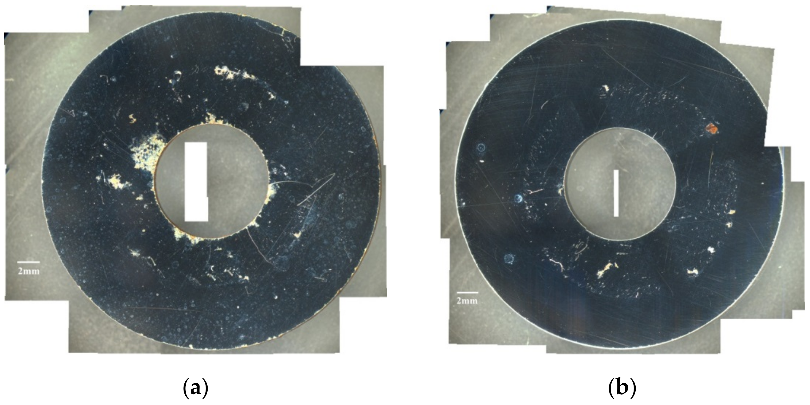
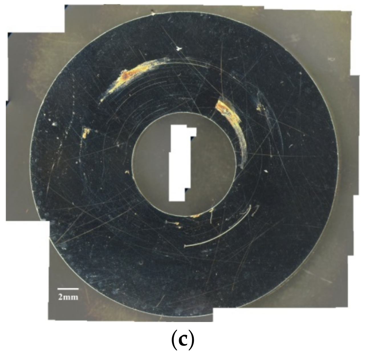
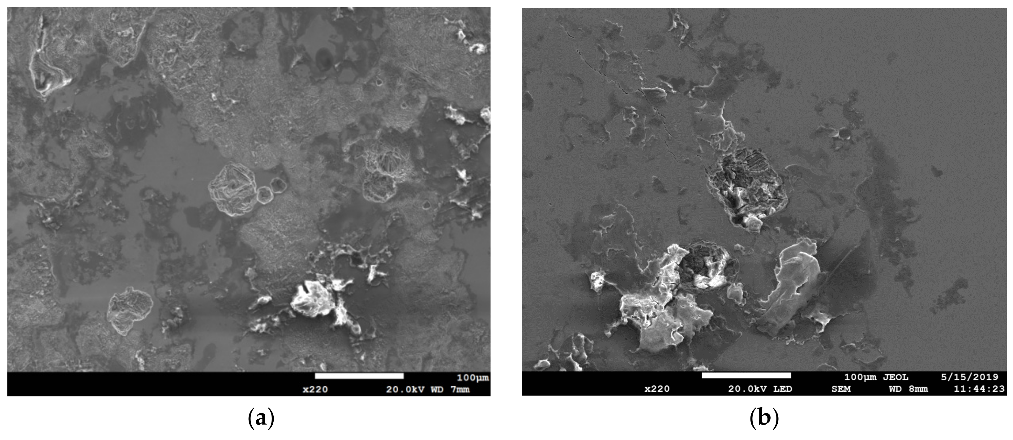
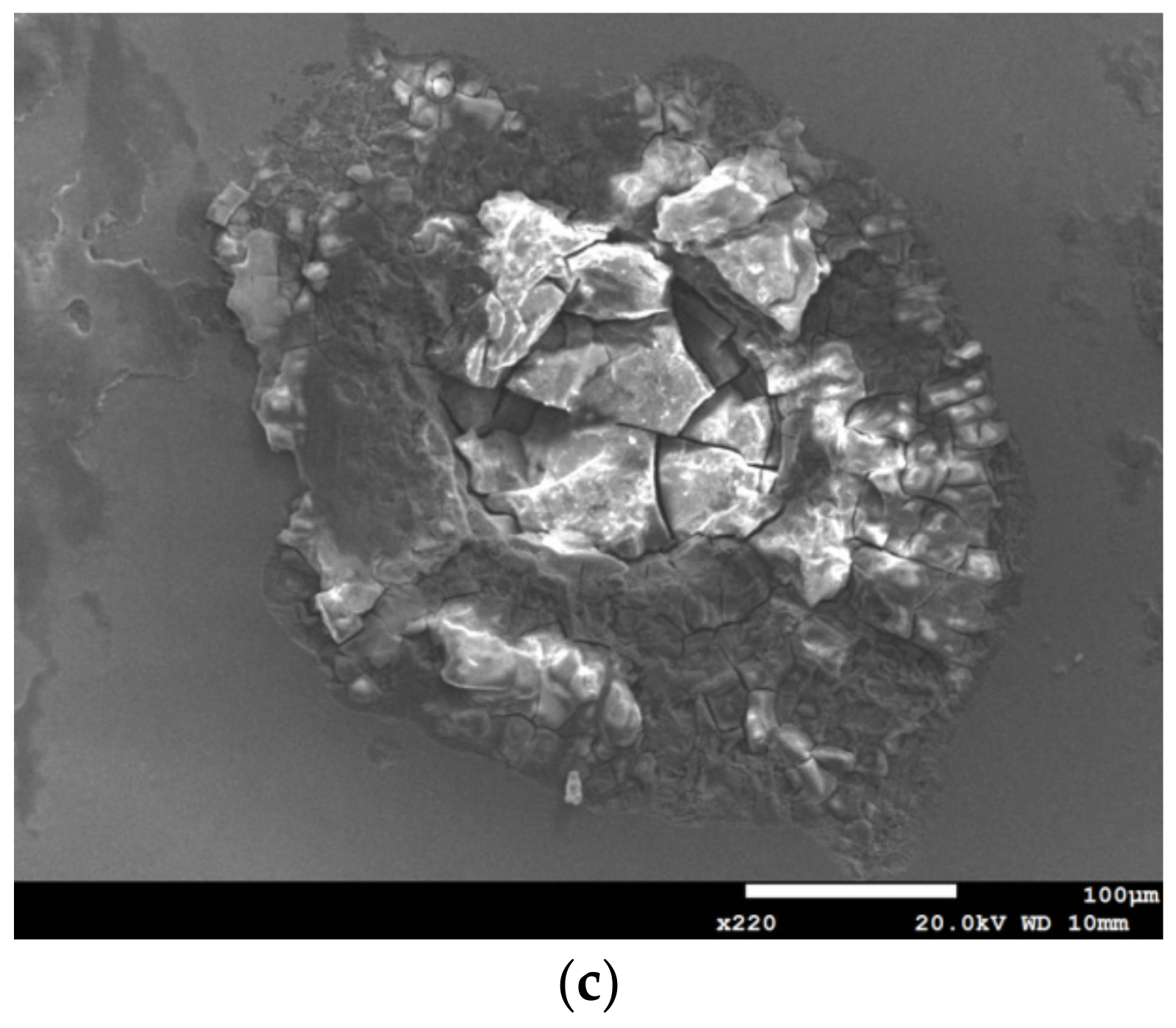
Figure 2 shows the surface morphologies of the 304L stainless steel at different levels of relative humidity with 0.1 g/m2 chloride concentration. Obvious crevice corrosion was observed in the corroded region. Figure 2a–c shows that the rusted areas decreased at RH = 55% but then increased at RH = 70%. This implies that the specimen surfaces had minimum rusted areas at RH = 55%. Figure 3 shows the SEM morphologies of corrosion products at different levels of relative humidity with 0.1 g/m2 chloride concentration. Figure 3a shows the morphologies of crevice corrosion. Rusts on the specimen correspond to crevice corrosion induced by chloride. Figure 3a–c shows that several rust spots were observed on the specimen, and shallow corrosion was observed under the rust spots. Figure 3b shows that the corroded areas were smaller compared to that shown in Figure 3a,c. Furthermore, no crack was found in the corroded region at all three different levels of relative humidity, as shown in Figure 3.
Figure 4 shows the surface morphologies of the 304L stainless steel at different levels of relative humidity with 1 g/m2 chloride concentration. Obvious crevice corrosion was observed in the corroded region. Figure 4a,b shows that there was little difference for the rusted areas under conditions with relative humidity of 45% and 55%, but the rusted areas obviously increased when the relative humidity increased to 70%, as shown in Figure 4c. Additionally, Figure 4 shows that more severe corrosion was observed at all three different levels of relative humidity compared to that shown in Figure 2. Figure 5 shows the SEM morphologies of corrosion pits at different levels of relative humidity with 1 g/m2 chloride concentration. Figure 5a shows the SEM morphologies of corrosion products after 5000 h tests with 1 g/m2 chloride concentration with RH = 45%. Rusts on the specimen correspond to crevice corrosion induced by chloride. Figure 5a,b shows that several rust spots were observed on the specimen, and shallow corrosion was observed under the rust spots. Figure 5c shows that the corrosion pits were larger compared to those shown in Figure 5a,b. Rust spots were also found on the specimen surface as shown in Figure 5c.

3.2. EDS and EBSD Analysis

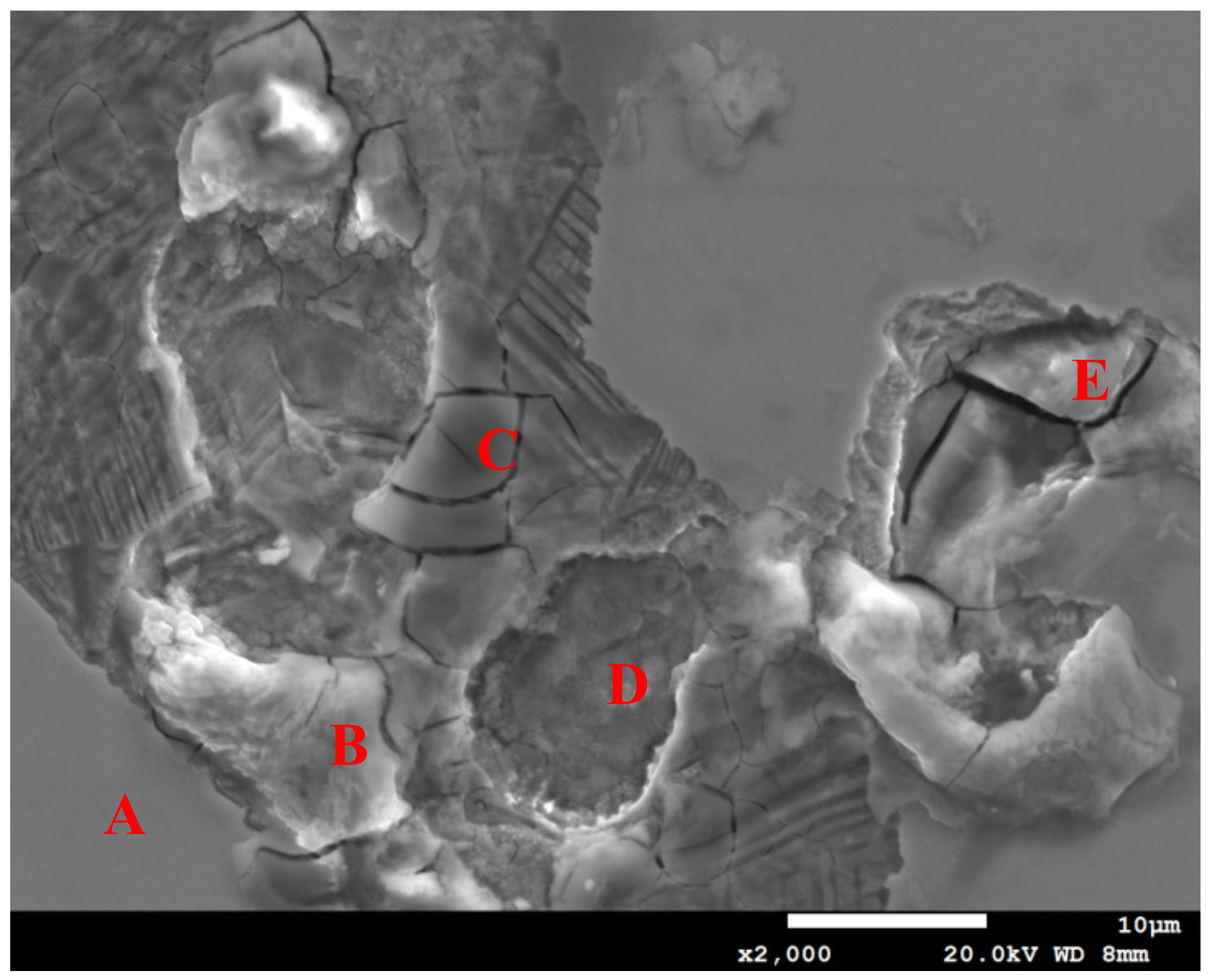
Figure 6 shows the EDS analysis results of the corroded region with 1 g/m2 chloride concentration and relative humidity of 45%. The EDS analysis results of the corroded region is listed in Table 3. The analysis result at point A shows that the sulfur and chlorine contents were too low to be detected at the stainless-steel matrix. The analysis results at points B, C, D, and E show that trace amounts of sulfur and chlorine were found in the oxide products. Moreover, the S content was higher at points B and E compared to that at point A. Sea synthetic water contains sulphates, and it may be the source of sulphur.
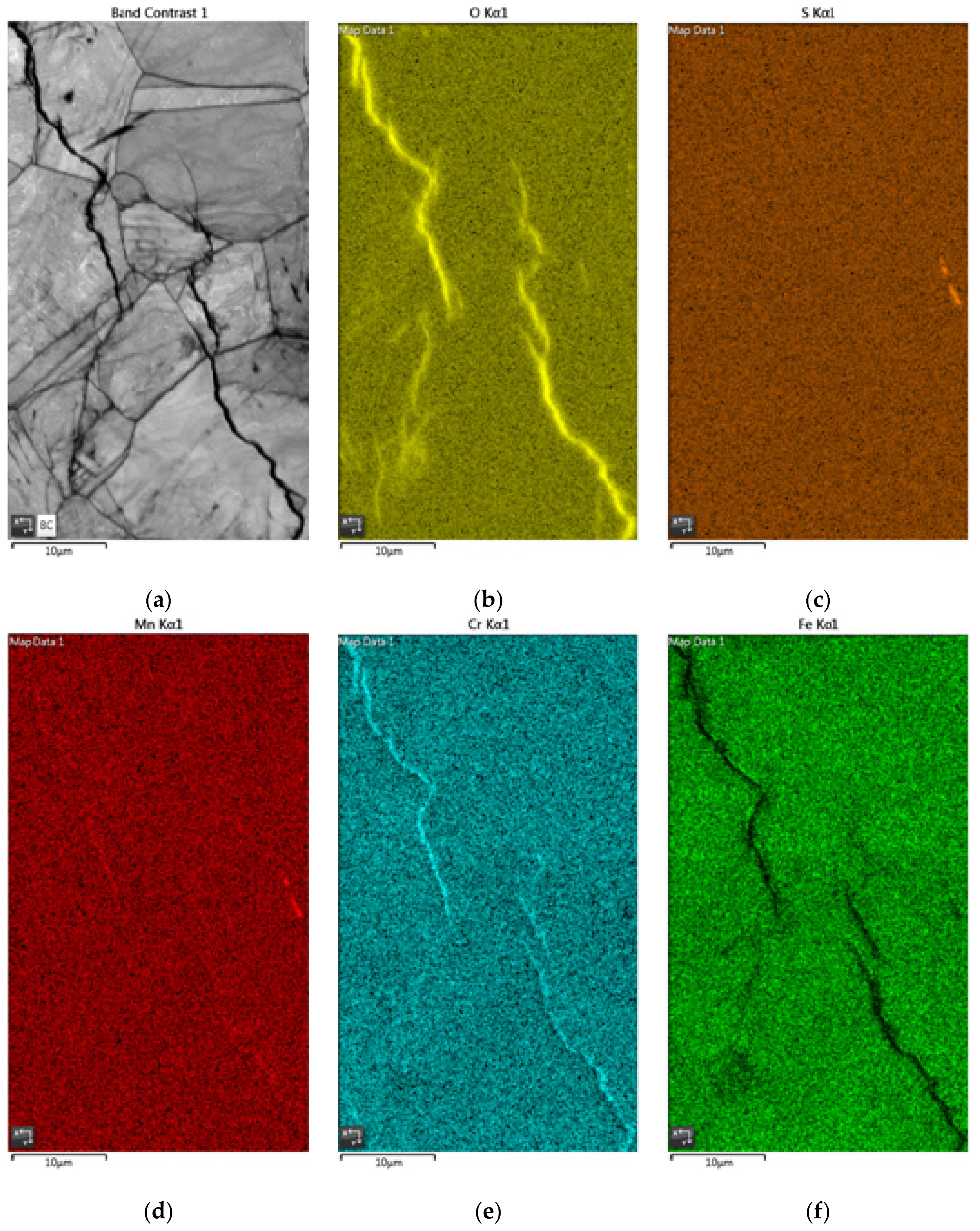
It is well known that the Cl ion is essential in the initiation of crevice corrosion. The CCS mechanism attributes the initiation of crevice corrosion to the accumulation of the aggressive ions, especially Cl in the crevice, leading to the appearance of highly aggressive local conditions that destroy the passive film of stainless steel [14,15,16]. At points C and E, the Cr content was much higher, but Fe content was much lower compared to that at point A. The reason behind the Cr enrichment may be the dissolution of Fe. It is supported by the EDS maps in Figure 8e,f. Then, points C and E would be local anodes. Additionally, it had much higher Fe content but lower O content at point D compared to that at points B, C and E, which implies that the oxide product was peeled off to reveal the metal surface. The trace amount of residual sulfide was also found at point D.
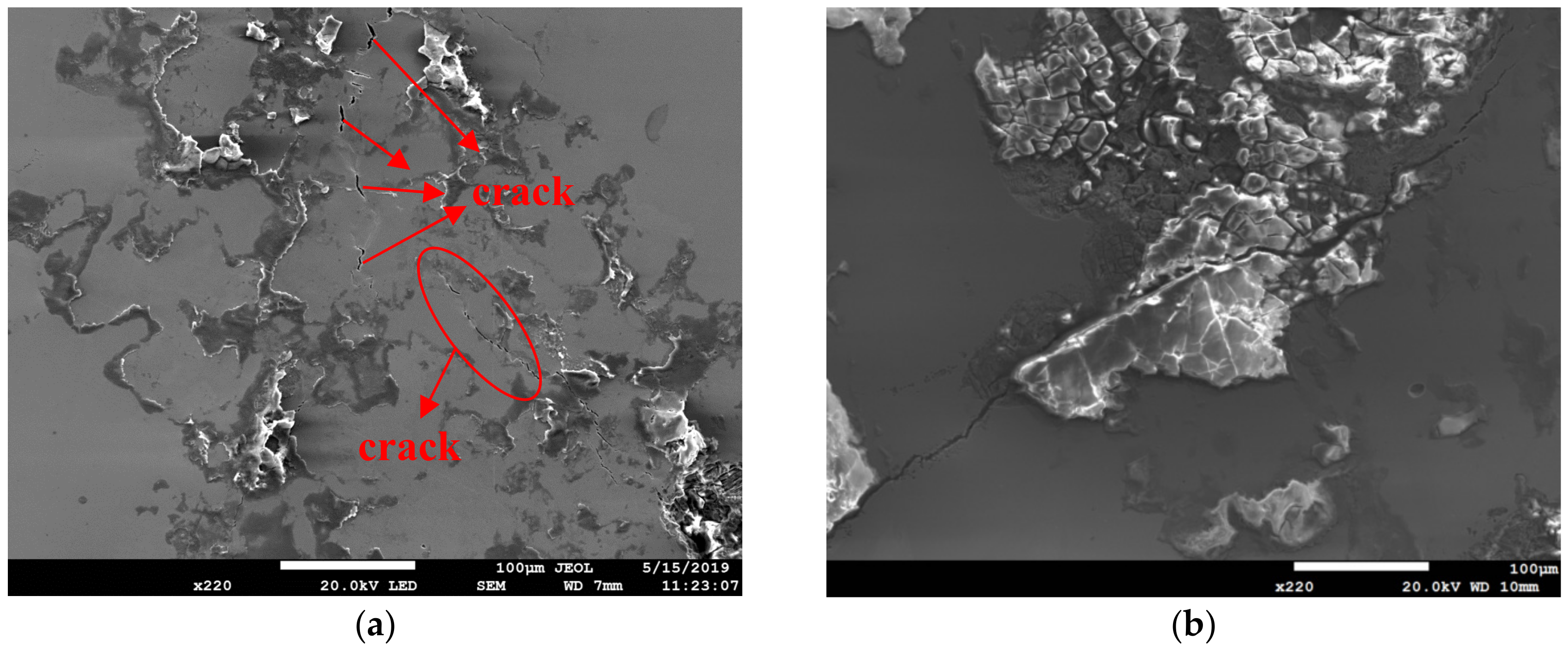
Figure 7 shows the SEM morphologies of stress corrosion cracking at different levels of relative humidity with 1 g/m2 chloride concentration. Although several rust spots were observed on the specimen and shallow corrosion was observed under the rust spots, no crack was found in the corroded region with relative humidity of 45% as shown in Figure 5a. Figure 7a,b shows that the distinct SCC cracks were observed on the specimen with relative humidity of 55% and 70%. Shoji and coworkers reported that MgCl2 is the sea salt constituent responsible for promoting low temperature AISCC in types 304L and 316L stainless steels. They observed the AISCC phenomenon in the 25 g/m2 chloride concentration of sea water [10]. Prosek and coworkers observed the AISCC phenomenon in the 260 g/m2 chloride concentration of MgCl2. The 1 g/m2 chloride concentration used in our study was much lower compared to that in the literature [10,11,13]. There was no SCC at RH = 45% whereas samples exposed at RH = 55 and 70% cracked with 1 g/m2 chloride concentration. In addition, no crack was found at all three different levels of relative humidity with 0.1 g/m2 chloride concentration, as shown in Figure 3. This may be explained by limited chloride transport into the crevice sites at the lowest RH (RH = 45%) with 1 g/m2 chloride concentration. The chloride may need a higher relative humidity environment to transport into the crevice sites due to the low chloride concentration. However, no crack was found at all three different levels of relative humidity with 0.1 g/m2 chloride concentration. It may be that the 0.1 g/m2 chloride concentration was too low to initiate SCC at any tested RH. Thus, these results suggest that the threshold relative humidity for SCC initiation of 304L stainless steel with 1 g/m2 chloride concentration at 45 °C is between 45% and 55% in this study. The volume increase of corrosion products may generate local stresses beneath the crevice former to cause the occurrence of SCC. Additionally, crack length was found to increase with an increase in relative humidity when comparing Figure 7a to Figure 7b.
Figure 8 shows the EDS mapping for the crack region with 1 g/m2 chloride concentration and relative humidity of 55%. It can be seen that oxygen and chromium were enriched whereas iron was depleted in the crack region. Additionally, Figure 8c shows that sulfur was enriched on the middle right side of the figure where manganese was also enriched at the corresponding site as shown in Figure 8d.
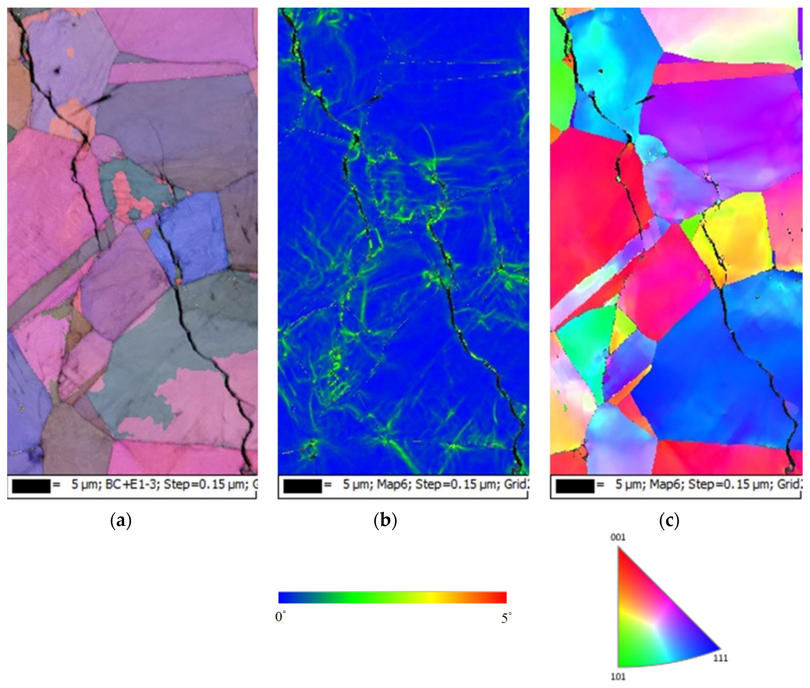
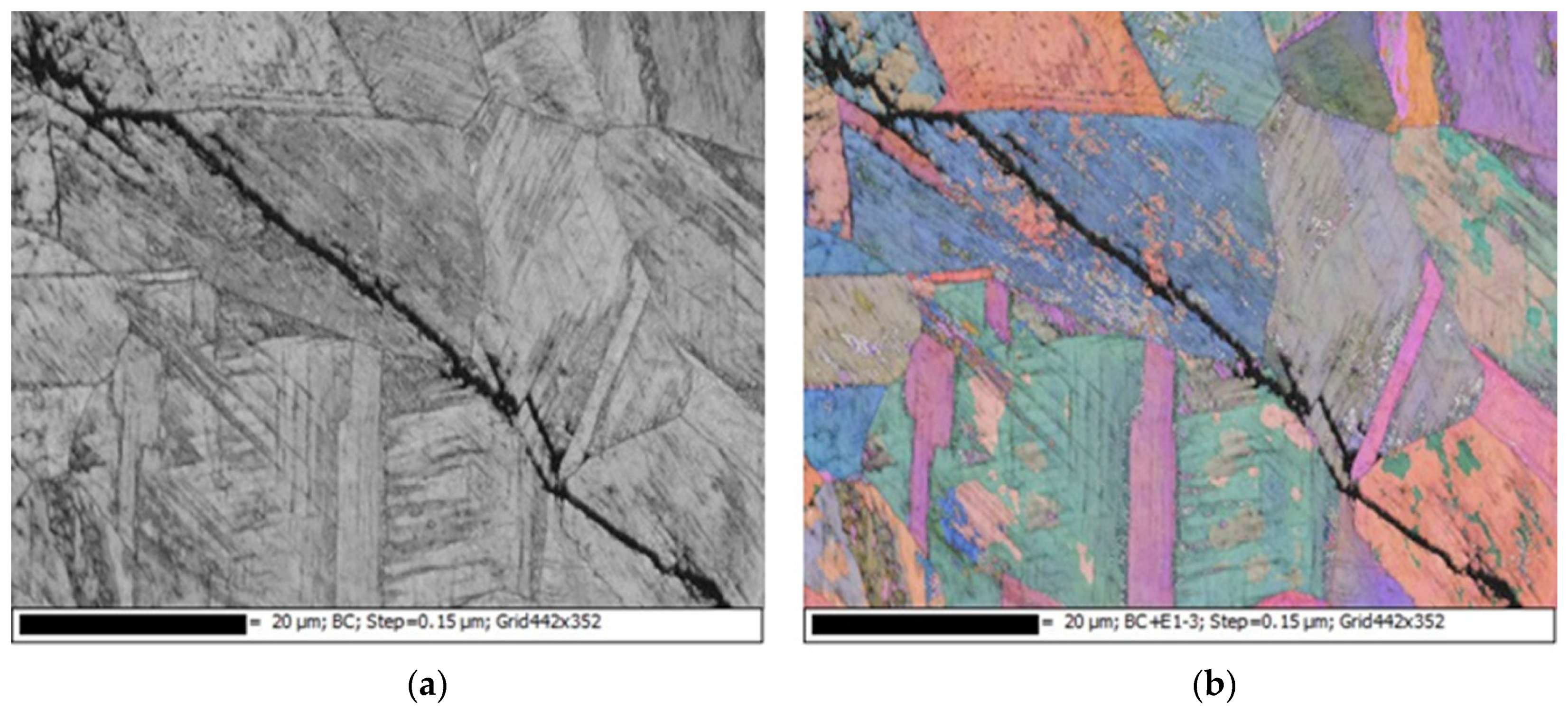
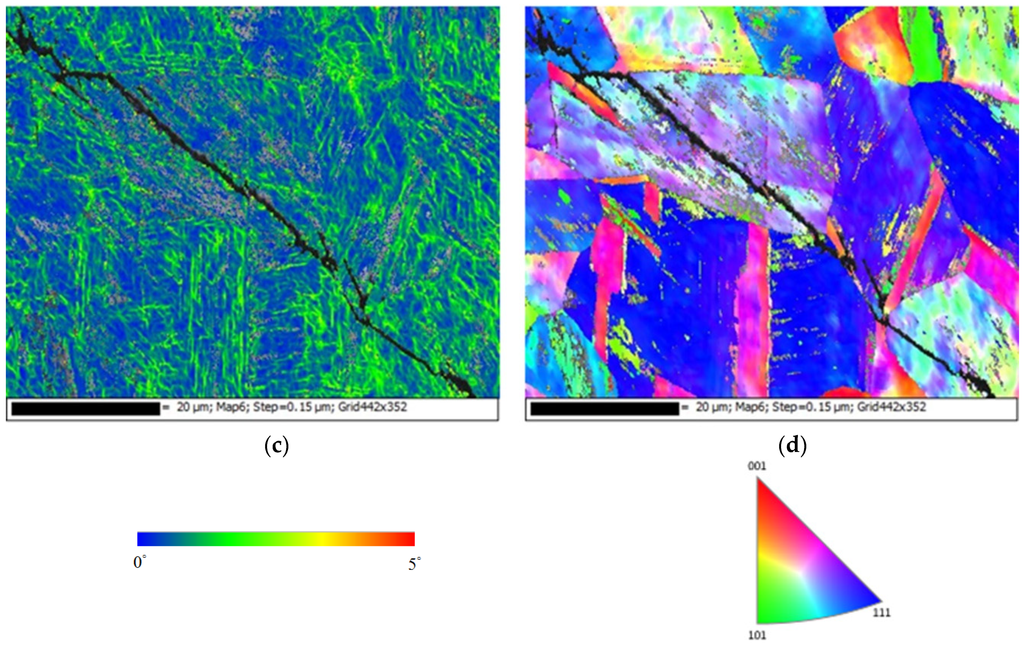
Figure 9 shows the EBSD maps for the crack region with 1 g/m2 chloride concentration and relative humidity of 55%. Figure 9a,c shows that the type of SCC on the specimen was transgranular SCC (TGSCC). Tani and coworkers reported that TGSCC induced by chlorides was observed at temperature above 50 °C in stainless steel [3], which agreed well with our results. The kernel average misorientation (KAM) map reveals that high plastic strain around the crack regions and the crack propagation was associated with plastic strain at the crack tip as shown in Figure 9b. Figure 10 shows the EBSD maps for the crack region with 1 g/m2 chloride concentration and relative humidity of 70%. Figure 10b,d shows that the type of SCC on the specimen was TGSCC, similar to Figure 9a,c. Figure 10c reveals that high plastic strain was around the cracks region.

4. Conclusions

In this research, crevice corrosion behaviors of 304L stainless steel with 0.1 and 1 g/m2 chloride concentration at 45 °C and different levels of relative humidity were investigated. Efforts were made to evaluate the effects of the relative humidity on the corroded regions and a threshold relative humidity for SCC initiation was proposed based on the experimental results. The results of this research suggest the following conclusions:
(1)
When the chloride concentration was 0.1 g/m2, the specimen surfaces had minimum rusted areas at RH = 55% and no cracks were found in the corroded region at all three different levels of relative humidity. It may be that the 0.1 g/m2 chloride concentration was too low to initiate SCC at any tested RH.
(2)
When the chloride concentration was 1 g/m2, there was little or no difference for the rusted area under conditions with relative humidity of 45% and 55%, but the rusted area obviously increased when the relative humidity increased to 70%. Additionally, several rust spots and shallow corrosion were observed, but no crack was found in the corroded region with relative humidity of 45%, whereas the distinct SCC cracks were observed with relative humidity of 55% and 70%. This may be explained by a limited chloride transport into the crevice sites at the lowest RH (RH = 45%) with 1 g/m2 chloride concentration. The chloride may need a higher relative humidity environment to transport into the crevice sites due to the low chloride concentration. Thus, this suggests that the threshold relative humidity for SCC initiation of 304L stainless steel with 1 g/m2 chloride concentration at 45 °C is between 45% and 55%.
(3)
The type of SCC on the 304L stainless steel at 45 °C was transgranular SCC, which was verified by EBSD results.

Author Contributions

Conceptualization, C.-P.Y. and K.-C.T.; formal analysis, C.-P.Y.; investigation, C.-P.Y.; project administration, J.-Y.H.; writing—original draft, C.-P.Y.; writing—review and editing, C.-P.Y. and J.-Y.H.

Funding

This research received no external funding.

Conflicts of Interest

The authors have no conflict of interest to declare.

References

  1. Guo, L.; Street, S.R.; Mohammed-Ali, H.B.; Ghahari, M.; Mi, N.; Glanvill, S.; Plessis, A.D.; Reinhard, C.; Rayment, T.; Davenport, A.J. The effect of relative humidity change on atmospheric pitting corrosion of stainless steel 304L. Corros. Sci. 2019, 150, 110–120. [Google Scholar] [CrossRef] [Green Version]
  2. Meyer, R.M.; Pardini, A.; Cuta, J.; Adkins, H.; Casella, A.; Qiao, A.; Larche, M.R.; Diaz, A.; Doctor, S.R. NDE to Manage Atmospheric SCC in Canister for Dry Storage of Spent Fuel: An Assessment; PNNL-22495 401001060; Pacific Northwest National Laboratory: Richland, WA, USA, 1 September 2013.
  3. Tani, J.I.; Mayuzumi, M.; Hara, N. Stress corrosion cracking of stainless-steel canister for concrete cask storage of spent fuel. J. Nucl. Mater. 2008, 379, 42–47. [Google Scholar] [CrossRef]
  4. Cai, B.P.; Liu, Y.H.; Tian, X.J.; Wang, F.; Li, H.; Ji, R.J. An experimental study of crevice corrosion behavior of 316L stainless steel in artificial seawater. Corros. Sci. 2010, 52, 3235–3242. [Google Scholar] [CrossRef]
  5. Abdulsalam, M.I. Behavior of crevice corrosion in iron. Corros. Sci. 2005, 47, 1336–1351. [Google Scholar] [CrossRef]
  6. Oldfield, J.W.; Sutton, W.H. Crevice corrosion of stainless steel-2. Experimental studies. J. Br. Corros. 1978, 13, 104–111. [Google Scholar] [CrossRef]
  7. Sharland, S.N. A review of the theoretical modeling of crevice and pitting corrosion. Corros. Sci. 1987, 27, 289–323. [Google Scholar] [CrossRef]
  8. Chen, D.; Han, E.H.; Wu, X. Effects of crevice geometry on corrosion behavior of 304 stainless steel during crevice corrosion in high temperature pure water. Corros. Sci. 2016, 111, 518–530. [Google Scholar] [CrossRef]
  9. Yang, Y.Z.; Jiang, Y.M.; Li, J. In situ investigation of crevice corrosion on UNS S32101 duplex stainless steel in sodium chloride solution. Corros. Sci. 2013, 76, 163–169. [Google Scholar] [CrossRef]
  10. Shoji, S.; Ohnaka, N.; Furutani, Y.; Saitoh, T. Effects of relative humidity on atmospheric stress corrosion cracking of stainless steels. Corros. Eng. 1986, 35, 559–565. [Google Scholar] [CrossRef]
  11. Cook, A.B.; Lyon, S.B.; Stevens, N.P.C.; Gunther, M.; McFiggans, G.; Newman, R.C.; Engelberg, D.L. Assessing the risk of under-deposit chloride-induced stress corrosion cracking in austenitic stainless steel nuclear waste containers. Corros. Eng. Sci. Technol. 2014, 49, 529–534. [Google Scholar] [CrossRef]
  12. Albores-Silca, O.E.; Charles, E.A.; Padovani, C. Effect of chloride deposition on stress corrosion cracking of 316L stainless steel used for intermediate level radioactive waste containers. Corros. Eng. Sci. Technol. 2011, 46, 124–128. [Google Scholar] [CrossRef]
  13. Prosek, T.; Iverson, A.; Taxsen, C.; Thierry, D. Low temperature on stress corrosion cracking of stainless steels in the atmosphere in the presence of chloride deposits. Corrosion 2009, 65, 105–117. [Google Scholar] [CrossRef]
  14. Nash, B.K.; Kelly, R.G. Characterization of the crevice solution chemistry of 304stainless-steel. Corros. Sci. 1993, 35, 817–825. [Google Scholar] [CrossRef]
  15. White, S.P.; Weir, G.J.; Laycock, N.J. Calculating chemical concentrations during the initiation of crevice corrosion. Corros. Sci. 2000, 42, 605–629. [Google Scholar] [CrossRef]
  16. Zhong, C.; He, M.F.; Liu, L.; Chen, Y.J.; Shen, B.; Wu, Y.T.; Deng, Y.D.; Hu, W.B. Formation of an aluminum-alloyed coating on AZ91D magnesium alloy in molten salts at lower temperature. Surf. Coat. Tech. 2010, 205, 2412–2418. [Google Scholar] [CrossRef]
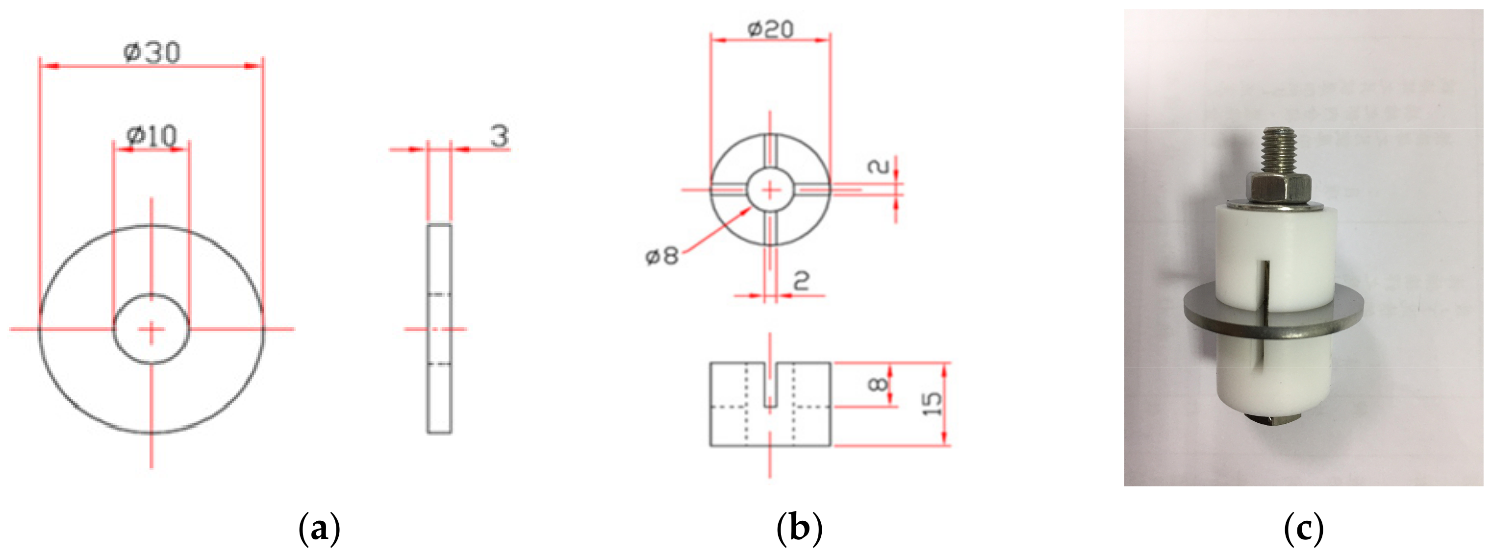
Figure 1. Shape and dimension of specimens used for crevice corrosion test. (a) Specimen, (b) crevice former, and (c) assembled image. (Unit: mm).
Metals 09 01185 g001
Figure 2. Surface morphologies of the corroded region after 5000 h tests with 0.1 g/m2 chloride concentration. (a) Relative humidity (RH) = 45%, (b) RH = 55%, and (c) RH = 70%.
Metals 09 01185 g002aMetals 09 01185 g002b
Figure 3. SEM morphologies of corrosion products after 5000 h tests with 0.1 g/m2 chloride concentration. (a) RH = 45%, (b) RH = 55%, and (c) RH = 70%.
Metals 09 01185 g003
Figure 4. Surface morphologies of the corroded region after 5000 h tests with 1 g/m2 chloride concentration. (a) RH = 45%, (b) RH = 55%, and (c) RH = 70%.
Metals 09 01185 g004
Figure 5. SEM morphologies of corrosion products after 5000 h tests with 1 g/m2 chloride concentration. (a) RH = 45%, (b) RH = 55%, and (c) RH = 70%.
Metals 09 01185 g005aMetals 09 01185 g005b
Figure 6. Energy dispersive X-ray spectrometer (EDS) analysis results of the corroded region after 5000 h tests with 1 g/m2 chloride concentration and relative humidity of 45%.
Metals 09 01185 g006
Figure 7. Stress corrosion cracking morphologies of specimens after 5000 h tests with 1 g/m2 chloride concentration. (a) RH = 55%, and (b) RH = 70%.
Metals 09 01185 g007
Figure 8. EDS mapping for the crack region after 5000 h tests with 1 g/m2 chloride concentration and relative humidity of 55%. (a) Band contrast image, (b) O mapping, (c) S mapping, (d) Mn mapping, (e) Cr mapping, and (f) Fe mapping.
Metals 09 01185 g008
Figure 9. Electron back scatter diffraction (EBSD) maps for the crack region after 5000 h tests with 1 g/m2 chloride concentration and relative humidity of 55%. (a) Euler map, (b) kernel average misorientation (KAM) map, and (c) inverse pole figure (IPF) map.
Metals 09 01185 g009
Figure 10. EBSD maps for the crack region after 5000 h tests with 1 g/m2 chloride concentration and relative humidity of 70%. (a) Band contrast image, (b) Euler map, (c) KAM map, and (d) IPF map.
Metals 09 01185 g010aMetals 09 01185 g010b
Table 1. Chemical composition of 304L stainless steel.
ElementCSiSCrMnNiFe
wt%0.0170.4500.02918.0001.5409.000Bal.
Table 2. Chemical composition of sea salt.
CompositionNaClMgCl2Na2SO4CaCl2KClNaHCO3KBrH3BO3SrCl2NaF
wt%58.49026.4609.7502.7651.6450.4770.2380.0710.0950.007
Table 3. EDS analysis results of the corroded region.
wt%OSClMnCrNiFe
A0.500.000.001.8019.07.9070.7
B44.80.900.800.7016.05.2031.6
C25.71.000.401.4030.74.0036.8
D9.700.100.401.3017.86.8063.9
E36.61.200.500.8031.45.1024.4