Article

A Numerical Investigation of a Single-Shot in a DEM-FEM Approach to Shot Peening Simulation

by
Aghogho Bright Edward
1,2,*,
P. Stephan Heyns
1 and
Schalk Kok
1
1
Center for Asset Integrity Management, Department of Mechanical & Aeronautical Engineering, University of Pretoria, Pretoria 0002, South Africa
2
Mechanical Engineering Department, Federal University of Petroleum Resources, Effurun 330102, Nigeria
*
Author to whom correspondence should be addressed.
Metals 2019, 9(11), 1183; https://doi.org/10.3390/met9111183
Submission received: 13 September 2019 / Revised: 4 October 2019 / Accepted: 11 October 2019 / Published: 2 November 2019

Abstract

:
Shot peening (SP) is a controlled and systematic process of surface treatment that has a large number of controllable process parameters that make its application highly challenging. It involves the shooting of small and hard metallic balls at a targeted surface, with the aim of enhancing the fatigue strength of the workpiece under unfavorable service conditions. The compressive residual stress (CRS) induced by this application is expensive to evaluate experimentally. This paper presents a numerical model of the impact of a single-shot on a metallic surface, with the aim to set the stage for a realistic multiple shots peening simulation. The approach proposed herein is a sequential Discrete Element-Finite Element (DE-FE) coupled simulation, based on the use of different types of coefficients of restitution (CoRs) with emphasis on the energetic CoR. The energetic CoR relates the shot/target contact forces to the fractional strain energy needed for localized plastic deformation of the near-surface layer in the workpiece. The generated results of the induced compressive residual stresses (CRS) and equivalent plastic strain (PEEQ) from single-shot simulations are validated with similar results from the literature. Our study clarifies the strain energy aspects of a single-shot impact responsible for the desired effects of CRS and PEEQ, thereby laying the groundwork for accurate and realistic modeling of the SP process via the DEM-FEM approach.

1. Introduction

Shot peening (SP) is one of the oldest mechanical surface enhancements of components for fatigue applications. Though it involves projecting a stream of energetic shots unto the surface of the component, a single-shot application to shot peening analysis has been the norm [1,2,3,4,5,6,7,8,9] from the start of analytical and numerical approaches. Single-shot simulation plays a very important role in developing a model for the proposed Discrete Element Method - Finite Element Method (DEM-FEM) approach to a realistic simulation of the SP process, in the current research work.
The SP process involves the shooting of small and hard metallic balls at the targeted surface, with the aim of enhancing the fatigue strength of the workpiece under unfavorable service conditions. Therefore, a single shot which is just an impact between two bodies, cannot represent the actual multiple shots as in shot peening but serves the purpose of giving insight into the formation of Compressive Residual Stress (CRS) on the surface of a workpiece subjected to this treatment.
A typical residual stress profile due to shot peening, is presented in Figure 1, been characterized by a surface compressive stress (σsur), a near-surface maximum compressive stress (σmax) at a beneficial depth (db), a total depth (dT) of compressive stress, and a tensile stress regime in the remaining section of the depth from the treated surface.
Typical profiles of the evolving trend of the residual stress as influenced by the thickness of the workpiece, the hardness of the shot, and its velocity was demonstrated in the work of Al-Obaid [10], where a workpiece with a thin section experiences an increase (a kick) in the tensile stress just after the total depth of compressive stress (plastic layer) as in Figure 1. This could aid the external tensile load applied in service, thereby initiating failure of the workpiece from within. That work also indicated that harder shots induce higher compressive stress in the near-surface regime of the workpiece, as well as shots with higher velocity capable of inducing both higher and deeper compressive stress, for enhanced fatigue life.
Al-Obaid [10] obtained a theoretical relationship between the plastic zone and some parameters of the shot and workpiece, which is useful in predicting the residual stress distribution along with the depth of a shot-peened workpiece, without having to resort to experimental measurements. However, there is a crucial shortcoming of the theoretical approach, which produces high tensile stresses at the transition from compressive to tensile stresses within the workpiece, due to huge assumptions made.
James et al. [11] related the fatigue performance of a component to residual stresses arising from the manufacturing and fabrication processes. They posit that residual stresses must be measured over a reasonable depth of several millimeters below the surface, for fatigue life prediction purposes.
However, affordable residual stress measurement practices such as the laboratory X-ray diffraction technique and incremental hole-drilling technique are not generally useful in the light of the above discussed. They embarked on a deeper depth measurement campaign, using synchrotron and neutron diffraction techniques, which are very expensive but capable of assessing the depth of the components, revealing the entire plastic zone and the transition pattern of the residual stress.
The importance of the issues highlighted above, and the limitations associated with the available option of an expensive experiment measurement technique such as synchrotron diffraction method, calls for the development of numerical models that incorporate both residual stress evaluation and fatigue life assessment due to an applied external load. This paper is, therefore, the first step of that endeavor for a realistic shot peening simulation with industrial relevance while maintaining the plasticity concept of the process.
The relevance of the impact created with a single-shot can be seen in the work of Gangaraj et al. [12] in which the estimation of multiple impact coverage was achieved by means of a numerical single-shot indentation, which is also applied in the work of Miao et al. [13].
There are several reports in the literature of single-shot numerical investigations such as Meguid et.al. [14], where a single-shot model was utilized in the study of the effect of shot velocity, size, shape, and the strain hardening coefficient on the plastic zone and residual stress field patterns created due to the indention of the metallic surface. In their work, it is indicated that the surface CRS and the maxima which occurs under the surface together with the compressed layer are influenced by the shot parameters such as velocity, shape, and size. Hong et al. [15] did a 3D finite element dynamic analysis of the single-shot impact on a component showing the effect of parameters such as impact velocity and angle, shot diameter, and initial yield stress of the workpiece on the residual stress distribution.
Al-Hassani [16,17] carried out both static and dynamic single-shot steel ball indentations, respectively, giving only the depth of the plastic zone as a response of the target impinged upon by a single sphere. The residual stress distribution along the depth and the axial direction from the point of impact on the surface were reported by the same author for a single-shot and a repeated single-shot impact at the same location on the surface. He was able to show the importance of strain rate in the distribution of stresses in the target, which is evident in the repeated impact.
With regard to the effects of peening parameters, Mann et al. [18] used a calibrated numerical single-shot via a nano-indentation experiment to study the near-surface hardness and residual stress, which resulted in the prediction of shot peening-induced residual stresses for an aluminum alloy. Hong et al. [15,19] used a single-shot impact on a metallic component to investigate the effects of the various peening parameters on the residual stress distribution. Among other findings, they reported that the shot diameter has a negligible effect on the magnitude of residual stress but that the depth increases linearly with increasing shot diameter. Hirai et al. [20] indicated numerically that the dent formed by a single-shot is influenced by the strain hardening parameter and the yield strength of both the shot and the peened material.
The importance of the materials involved in the SP process can be observed in the work of Sanjurjo et al. [8], who utilized a single shot experimentally and numerically in the analysis of commonly used constitutive material models and their response to monotonic loads. The study indicated that the Johnson–Cook material model gave a dimple diameter closer to that obtained experimentally for duplex stainless steel when compared with the Cowper–Symonds model and modified versions of the Johnson–Cook or Cowper–Symonds models.
All the simulation works highlighted so far are based on the finite element method, and none of these properly predicted the CRS profile obtained experimentally by Mori et al. [21] and Kobayashi et al. [22] for a single-shot. They investigated a single-shot impact on a metallic surface experimentally and reported a difference in the static and dynamic indentation with regard to the residual stress, which is tensile in a single-ball dynamic test at the center of the dent, while that of a static indentation is compressive or near zero at the center. However, as more dents are created close to an isolated one due to multiple shooting, the tensile residual stress at the center of a single dent becomes compressive. Shivpuri et al. [5] and Zion et al. [23] confirmed these findings with numerical simulations supported by experimental results.
Xiao et al. [24] used results from single and repeated impacts to establish a model to calculate the random peening stresses in peen forming operations. They showed that the depth of a repeated impact fluctuates, revealing the loading and rebounding of the impact regime. A relationship was eventually established between the maximum depth of each impact and the diameter of the dimple created.
It should be noted that even in cases where the reported residual stress profiles for a single-shot do not conform to experimental reports, they do, however, give insight into the relationship between the SP parameters and CRS. The use of FEM in simulating the complex SP process for a realistic outcome is currently not practicable due to the huge number of shots (over a million) involved. This is further compounded by the complex velocity distributions of the shots influenced by the nozzle design and settings, coupled with the shot-shot collisions, which reduces their initial velocity at impact.
Current computer resources required to use Finite Element Method (FEM) alone for realistic shot-peening investigations are still not feasible. This paved the way for the use of the discrete element method (DEM) more recently, either alone or coupled with FEM concurrently by Han et al. [25], Jebahi et al. [26], or sequentially by Murgaratnam et al. [27], Bhuvaraghan et al. [28], and Fubin-Tu et al. [29], to overcome the challenges associated with the FEM method.
In their study, Han et al. [25] adopted a soft model for the shot, since both shot and workpiece are physically deformable, instead of the assumed rigid shots model commonly used by many researchers in the literature. Their results conform to experimental profiles obtained for a single-shot, where tensile residual stress is obtained directly under a single-shot indentation. However, they referred to this occurrence as an abnormality associated with the use of a 2-D FE model. This is actually not the case, considering the work of Shivpuri et al. [5] and supported by that of Lewis et al. [23], where similar results were obtained with a 3D FE analysis.
Soady [30] highlighted the issue of the overestimation of CRS in a literature review drawing the attention of the SP research community to the experimental works of Wang et al. [31] and that of Gao et al. [32]. These authors used empirical formulations to relate CRS to the yield stress of the treated workpiece and the SP process parameters, showing that the CRS is a fraction of the yield stress or ultimate tensile stress of the workpiece and not a multiple of those values. The overestimation of CRS is considered to be a pitfall in the strain rate effect included in the material model mostly by the application of the Johnson–Cook constitutive model. Gangaraj et al. [12] did a numerical investigation on the effect of the mesh size on the residual stress convergence and obtained a realistic CRS profile for a single-shot simulation. They established that the ratio of mesh size to dimple size created by the shot should not be larger than 1:10 for the shot and 1:20 for the workpiece, especially in the impact zone.
In light of the above discussions, this paper is aimed at enhancing the DEM-FEM approach previously developed by Edward et al. [33] for a simplified numerical simulation of a realistic SP process. This is needed in order to set the stage for developing a numerical framework that captures all the relevant shot parameters that are of industrial relevance while maintaining the principles of impact mechanics in the SP process simulation.
To the authors’ knowledge, the proposed DEM-FEM approach, which is sequential in nature, is one of its kind, where the direct application of imported peening forces from DEM is used in FEM for predicting the workpiece response to a realistic SP process. The work is patterned after the work of Bhuvaraghan et al. [28], where the pressure equivalent of the force was applied to the component using a fixed dent size of a single normal impact as the area of contact via an approximated mesh size. That approach, however, has considerable limitations with respect to a realistic SP process, as highlighted by Fubin-Tu et al. [29], as well as with respect to its accuracy, since dents formation in a realistic SP cannot be uniform. The radius of the dent formed depends on the angle of impact, which is seldom normal to the workpiece surface, more so considering the shot-shot collision effects, which reduce the likelihood of a normal impact.
The main objective of this paper is to establish the basis for a proposed DEM-FEM framework [33] needed to simulate a realistic SP process, by means of single-shot impact analysis from an applied mechanics perspective. This approach utilizes the plastic strain energy component of a single-shot impact, as opposed to the reactive contact force component utilized by previous work [28].
The reactive contact force is responsible for the rebound of the shot and cannot produce the same plastic strain resulting from the impact. In the present work, we convert the plastic strain energy of a single-shot impact into contact forces by use of the energetic CoR instead of the kinematic CoR of the collision. A DEM model is subsequently coupled with combined implicit/explicit FE models, which enhance the direct application of the exported force, thereby overcoming the limitations of the DEM-FEM approach of Bhuvaraghan et al. [28].
The remaining part of this paper is organized as follows: a theoretical background for the numerical formulation of the DEM-FEM model; simulation of a single-shot using the newly proposed model, results, and validation, as well as a discussion of the results and conclusions.

2. Theoretical Background

In formulating a DEM-FEM model for a realistic SP simulation, the authors consider the mechanics of the process with respect to the impact of a single-shot on the workpiece surface as shown in Figure 2. The kinetic energy of the shot at impact Wi, and that at rebound Wr, corresponds with the impact velocity vi and the rebound velocity vr at angles α and α’ respectively. During impact, contact forces are generated briefly between the bodies at the region of overlap, with deceleration and acceleration of the shot accompanied by rapid energy dissipation. The impact is partially plastic involving energy loss of a fraction of the impact energy of the shot at collision, with plastic deformation of the workpiece. The shot can either be considered rigid, with no plastic deformation or deformable, and then it will experience flattening.
Generally, from the first principles, energy balance can be represented as
W i = W r + W p + W d
where Wi is the kinetic energy at impact, Wr is the restituted energy, Wp is the energy used for plastic deformation in the workpiece, and Wd is the energy dissipated through elastic stress wave propagation, heat due to friction etc., which is not recoverable.
The total kinetic energy loss (WL) by the shot of mass m due to impact is, therefore:
W L = W p + W d
It should be noted that W i = 0.5 m v i 2 is identical for both DEM and FEM simulations for a single-shot, since the impact or initial velocity vi is the same in both cases. The total kinetic energy lost by the ball due to impact with the workpiece can be determined by the CoR obtained from an FE analysis of the impact. To date, researchers have used experiments and finite element analysis (FEA) to obtain the value of CoRs for specific materials. However, in order to focus on the main objective of this paper, we simply refer to a review work by Ahmad et al. [34] where different CoR models, with their pros and cons, were highlighted.
Ahmad et al. [34] highlighted three definitions of CoR, which are the kinematic CoR, kinetic CoR, and the energetic CoR, stating that only the energetic CoR can provide the correct solutions in all cases. This includes impact involving friction and a change in the direction of slip during the collision. For a specific material impacted by a shot, the CoR is calculated based on the normal component of the relative velocities, material properties and geometry of both bodies involved in the collision, as well as the sliding friction. From the review, it was found that an increase in the number of impacts at a specific spot, also increases the reactive contact force and CoR due to surface hardening by plastic deformation. This gives an indication that the maximum reactive contact force exacted by the target (workpiece) on the shot is responsible for the rebound phase of the shot.

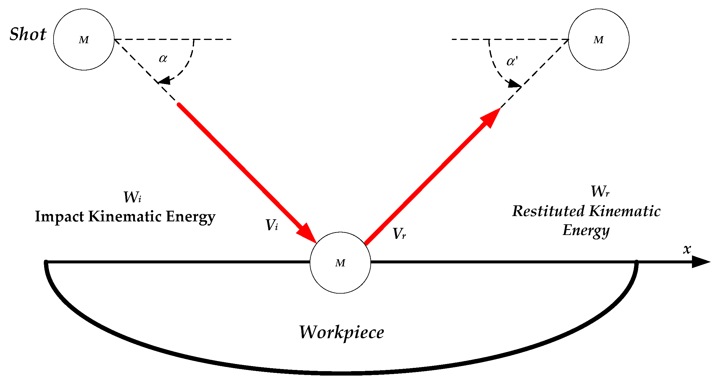
2.1. CoR Calculations for Single-Shot Impact in DEM

The coefficient of restitution (CoR) is simply the ratio of the shot velocity (vr) just after a rebound to its velocity (vi) before impact. In an FEM, simulation that includes the dominant physical effects (e.g., plastic dissipation, wave propagation, contact, and friction), the CoR can be computed and can subsequently be used to determine the energy loss. This classical definition of the CoR is known as the kinematic CoR. In a DEM simulation of numerous particles impacting on the workpiece, a CoR must also be defined. However, if the DEM simulation only simulates elastic contact (as is frequently the case), then the CoR obtained from the FEM simulation ( e F E M ) would not be the appropriate value to use in the DEM simulation.
In the present work, the CoR to be used in DEM ( e D E M ) is computed from the energetic CoR, denoted (Er), and Er is defined as the ratio of the shot kinetic energy after impact to that before impact.
E r = 0.5 m v r 2 0.5 m v i 2 = v r 2 v i 2
Er in Equation (3) can be used to obtain the contact force to be exported from the DEM model to the FEM model. The absolute value of (vr/vi) is the kinematic CoR obtained from a single-shot simulation in FEM, and m is the mass of the shot. It should be noted that Er is the fraction of the impact energy of the shot restituted on its rebound due to the reactive contact force by the workpiece. Therefore:
E r = ( v r v i ) 2 = ( e FEM ) 2
Equation (4) is a very important relationship between the energetic CoR (Er) and the kinematic CoR of the impact either in DEM ( e D E M ) or in FEM ( e F E M ). The total energy loss experienced by the shot can be expressed as:
W L = ( 1 E r ) W i
W L = [ 1 ( e F E M ) 2 ] W i
It has also been reported that between 80 percent and 90 percent [35,36] of the kinetic energy loss by the shot to the workpiece during a mechanical impact is used in doing plastic work in the workpiece, assuming the shot to be rigid. The assumption of a rigid shot is appropriate for a shot peening process since the shot is much harder compared to the workpiece in most cases.
A detailed analysis of the energy balance for a single-shot impacting a workpiece is obtained in the works of Thornton [37] and Fathallah et al. [36]. Considering the mechanics of a single-shot impact, the kinetic energy of the shot just before impact constitutes its rebound kinetic energy and the total energy lost. Therefore, the energy relation in Equation (4) can be used to obtain the needed contact force to be exported from the DEM model to the FEM model.
A minimum of 80 percent of the total energy loss (WL) for a single-shot in elastic-plastic impact is used in the plastic deformation of the workpiece. Therefore, equivalent energy via contact forces is required to be exported from DEM to FEM sequentially in order to maintain a realistic simulation of the SP process using the proposed DEM-FEM approach. An appropriate CoR to be implemented in DEM (eDEM) has to be determined using Equation (7), with the minimum fraction (0.8) of the total energy loss (WL) chosen instead of 0.9, for a conservative estimate.
W plastic = 0.8 W L
W plastic = 0.8 [ 1 ( e FEM ) 2 ] W i
The use of 0.8 in Equation (7) is justified considering the fractional kinetic energy loss λ = 1 − k, where k is the efficiency coefficient related to the elastic and thermal dissipation in a purely elastic impact. This efficiency coefficient is from the findings of J. Reed, which were reported and referenced by Sherafatnia et al. [38]. Reed stated that k is given a constant value of 0.8 in most works reported in the literature, and also observed that a portion of the energy induced into the workpiece by the shot in purely elastic impact is dissipated as radiation of elastic waves and cannot be recovered. This fraction (λ) of the total kinetic energy loss, therefore, determines the maximum possible value of the CoR for any impact.
From numerical investigations carried out by the authors of the present work, it is evident that the recorded contact forces to be exported to the FEM domain from the DEM domain are responsible for the rebound of the shot during the offloading phase in DE analysis. It should be noted that these reactive contact forces in the DEM domain are not the same in magnitude as the contact forces in the FEM domain, even when the kinematics of the impact is maintained. It is instead required that the exported contact forces from the DEM model must produce the same plastic strain in the FEM model, considering a single-shot analysis with FEM only.
Though the impact velocities vi in both FEM and DEM are the same, the CoR to be implemented in DEM ( e D E M ) has to be determined using Equations (4) and (8). Thus, equating the energy restituted in the DEM simulation for a single-shot with the same impact velocity as in FEM domain, to the energy lost due to plastic work in FEM, we have:
E r _ DEM W i = W plastic
( e D E M ) 2 W i = 0.8 [ 1 ( e F E M ) 2 ] W i
e DEM = 0.8 [ 1 ( e FEM ) 2 ]
From Equation (11), a FEM simulation of a single-shot that results in a CoR ( e F E M ) of 0.4 will require a CoR ( e D E M ) of 0.82 if a collision is implemented in EDEM (a discrete element software) using the Hertz–Mindlin (HM) no-slip contact model [39], in order to obtain the same contact force as in the FEM. This is due to the DEM analysis being purely elastic, but uses the kinematic CoR to mimic the elasto-plastic collision in the FEM. Thus, the DEM serves as a very potent tool in achieving a realistic multiple shots simulation, of a complex shot peening process when coupled with the FEM.

2.2. The Use of Contact Laws for a Single-Shot Impact in DEM

Considering a typical single-shot impact shown in Figure 2, for a DEM domain using the EDEM commercial software, the issue of concern in simulating the process in this research is the contact forces generated due to the interaction laws governing the impact. For a detailed analysis of existing contact models that predicts the contact force due to the impact of a particle with a flat surface (workpiece) please refer to the work of Han et al. [25].
The contact models available in EDEM, which are of interest to this work is the Hertz–Mindlin (no-slip) model and the hysteretic spring model (HS). The Hertz–Mindlin (HM) model can calculate contact forces efficiently, but the shot is considered a rigid body. The HS model could be used to accommodate a real plastic deformation effect in the particle. It should, however, be noted that only one of these two models could be implemented at a time when performing a simulation using the EDEM software.
The HM model uses the CoR as indicated in Equation (4) of Section 2.1, in evaluating the fraction of the impact energy, which is restituted, thus describing the impact kinetics. In contrast, the HS model uses the set CoR in a completely different way with the normal and tangential force calculations based on the Walton-Braun theory as detailed in the EDEM user guide [39]. While the CoR of the collision in the HM model takes the value implemented irrespective of the velocity of the shot, the CoR of the collision in HS model changes with the velocity of the shot, irrespective of the fixed CoR implemented.
It should be noted that the reactive contact forces obtained by the use of the HS model could be calibrated to obtain the same plastic strain in FEM. This is made possible by assigning predetermined yield stress for the deformable shot, which is evaluated numerically at the different shot velocities.
The application of the HM model by Bhuvaraghan et al. [28] showed a 27% difference between the maximum contact force obtained for the same single-shot simulation in DEM (87.8N) and FEM (111.6N). This could result in huge discrepancy in the simulated CRS when applied to multiple shots in the SP analysis. However, these authors did introduce a correction factor to calibrate the DEM force to the reactive contact force in FEM, via a look-up table that normalizes the values obtained. Notwithstanding, the force obtained by their approach could not produce the same plastic strain in the FEM, and the simulation time will be extended by the use of a look-up table.
Section 5. of the present work shows that the maximum contact force needed to be generated in the DEM that will produce the same plastic strain in FEM cannot be obtained with the HM model, for a predetermined shot velocity. This suggests a need to properly evaluate the CoR to be used in DEM via the HM contact model in a bid to determine the required force and justifies the preferred use of the HS contact model in the proposed DEM-FEM approach to a realistic SP simulation.
The HS model available in EDEM is calibrated numerically by several trials runs at the different velocities, to generate the required force that will produce the same plastic strain in FEM. A calibrated, yield stress of 2.3 GPa, 2.785 GPa, and 3.2 GPa is obtained for the 0.3556 mm, 0.7 mm, and 1.0 mm shots, respectively.

3. Numerical Formulation of the DEM-FEM Model for a Single-Shot Simulation

3.1. DE and FE Material Models Characterization

In line with the purpose of this study, the mechanical properties of the shots and workpieces shown in Table 1, were adopted from the literature for all the simulations, both in DEM and FEM.
A Johnsons-Cook (JC) constitutive model [41] is selected to capture isotropic hardening and strain rate hardening effects for the workpiece material with thermal softening. The JC model expressed as:
σ y = [ A + B ( ε eff p ) n ] ( 1 + C ln ε · ) [ 1 ( T H ) m ]
is available in the Autodyn Explicit dynamics code in ANSYS. In Equation (12), σy is the equivalent yield stress, A is initial yield stress, B is the hardening constant, C is the strain rate constant, n is the hardening exponent, and m is the thermal softening exponent. ε · = ε · eff p ε · 0 is a dimensionless strain rate, with ε · 0 a reference strain rate at which A was obtained. ε · eff p is the effective plastic strain, and T H = T T R T M T R is the homologous temperature, TR is the reference temperature, TM is the melting point of the material, and T is the effective temperature.
Table 2 summarizes the Johnson–Cook material parameters obtained experimentally and reported in the literature by various authors. These parameters were used together with the corresponding mechanical properties in Table 1. The strain rate effect was not considered for the shot since the focus here is on the response of the workpiece to the impact. More so, the shot in this analysis is considered to be rigid and does not result in any significant difference with strain rate considered. Thus, a purely elastic material model, in accordance with Table 1, was used for the shot throughout this work in the FEM impact analysis. Cast steel shots of 0.7 mm and 1.0 mm sizes are used for the peening of the workpieces made of AISI 4340 material in this work, while the cut-wire shot (CW-14) of size 0.3556 mm is used for the peening of the workpiece made of Inco718 material.

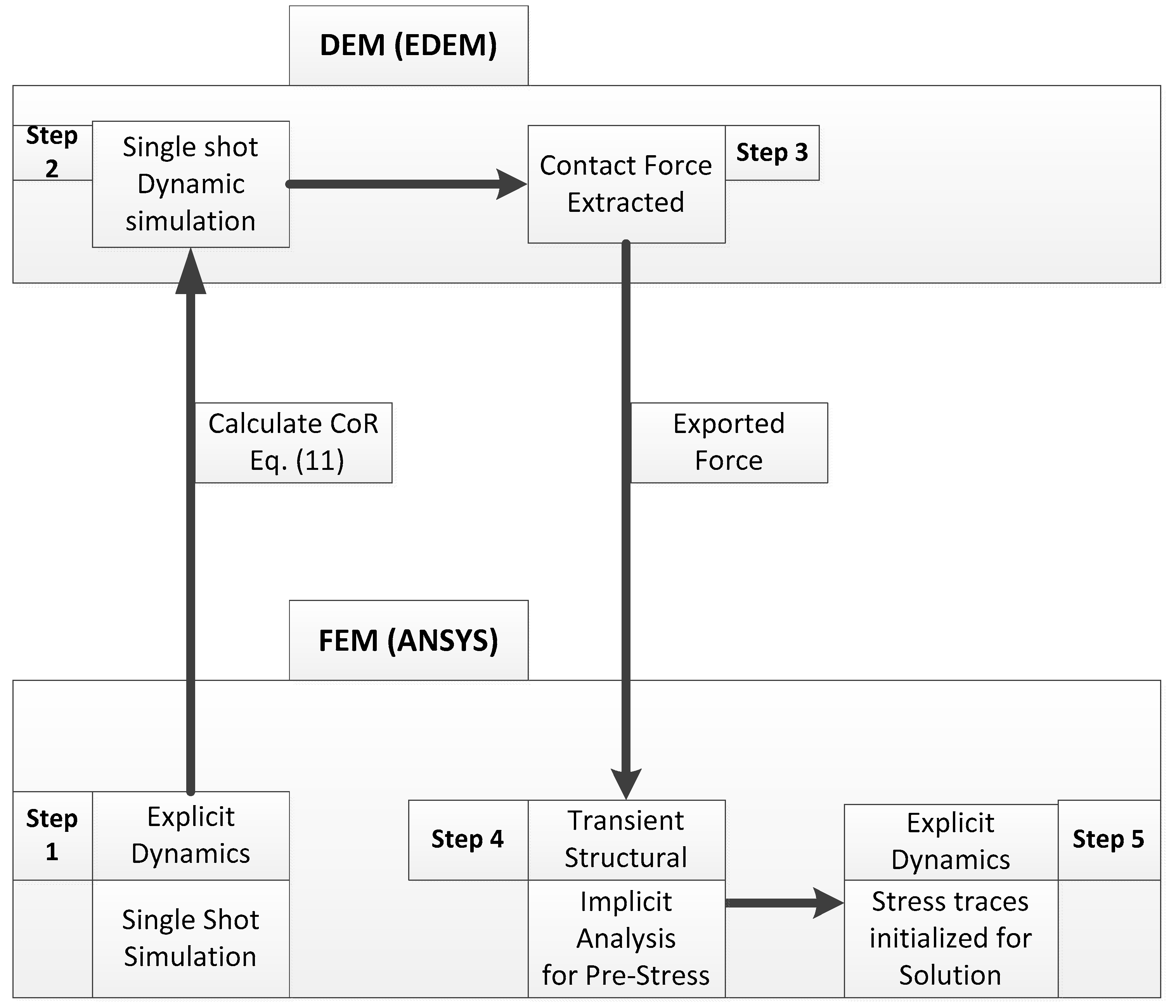
3.2. A Process Map for DEM-FEM Coupled Analysis

In the present work, the contact force evaluated from a single-shot impact in the DEM domain using the EDEM commercial software is exported to the FEM domain using ANSYS for the purpose of pre-stressing the same workpiece in Explicit Dynamics (ANSYS Autodyne software) via a transient structural scheme. Figure 3 shows a process flow map of the proposed DEM-FEM analysis considering a single shot.
A single-shot impact in EDEM using the calculated CoR obtained from the same single-shot analysis in FEM is carried out to obtain the required contact force. The contact force is subsequently exported to the ANSYS platform as a force load, for CRS and PEEQ evaluation. Equivalent (von Mises) stresses initiated by the imported force load via the ANSYS implicit solver (transient structural) are then applied to the same workpiece in ANSYS Autodyne for explicit analysis. The final results that consist of dent size, CRS, and the Equivalent Plastic Strain (PEEQ) are obtained in Step 5 of the process, but only the CRS and PEEQ are validated with available experimental and numerical results from the literature.

4. Single-shot Simulations

4.1. FEM Dynamic Simulation for CoR Calculation

For brevity, an analysis of a single shot simulation of 0.3556 mm CW-14 shot on the surface of an Inco718 workpiece is presented here. However, the same approach applies to other shot types and targets. A unit cell is modeled using a 0.0072 mm mesh size at the contact surfaces of both shot and workpiece, and more coarse meshes up to 0.03 mm size in other parts of the workpiece. The shot is discretized with 231,065 463,704 elements of 4 noded tetrahedral meshes (element type Tet4) while the workpiece has 463,704 elements of 8 noded hexahedral meshes (element type Hex8), with edge sizing of 20 divisions and a bias factor of 1.1 increments from the surface to the bottom along the four vertical edges. Symmetric boundary conditions are applied to the four vertical faces with the bottom face completely fixed in Figure 4. However, for the bigger particles (0.7 mm and 1.0 mm diameter shots), a workpiece of size 3.6 × 3.6 × 1.29 mm is modelled with a mesh size of 0.017 mm and 0.02 mm, respectively, at the contact surfaces.
Step 1 of the flow process shown in Figure 3 was executed with a rigid shot of 0.3556 mm, targeted at the midpoint of the top face of workpiece, in the normal direction, as shown in Figure 4. The single shot explicit dynamics run in Ansys mechanical took a total of 218.623 min on four slaves, in an Intel i7 [email protected] GHz of 16 GB Random-access memory (RAM) Notebook. The CoR obtained is used in calculating the required CoR to be implemented in Step 2 of the process. Therefore, the CoR to be implemented in DEM must be properly determined with an accurate FE model, so as to obtain the required contact force that will be exported to FEM, for structural analysis. It should be noted that in determining the needed force at this phase of the schematics in Figure 3, the same single shot simulations are carried out in both the FEM (step1) and DEM (step2) without coupling. This resulted in the data presented in Table 3 and Table 4.

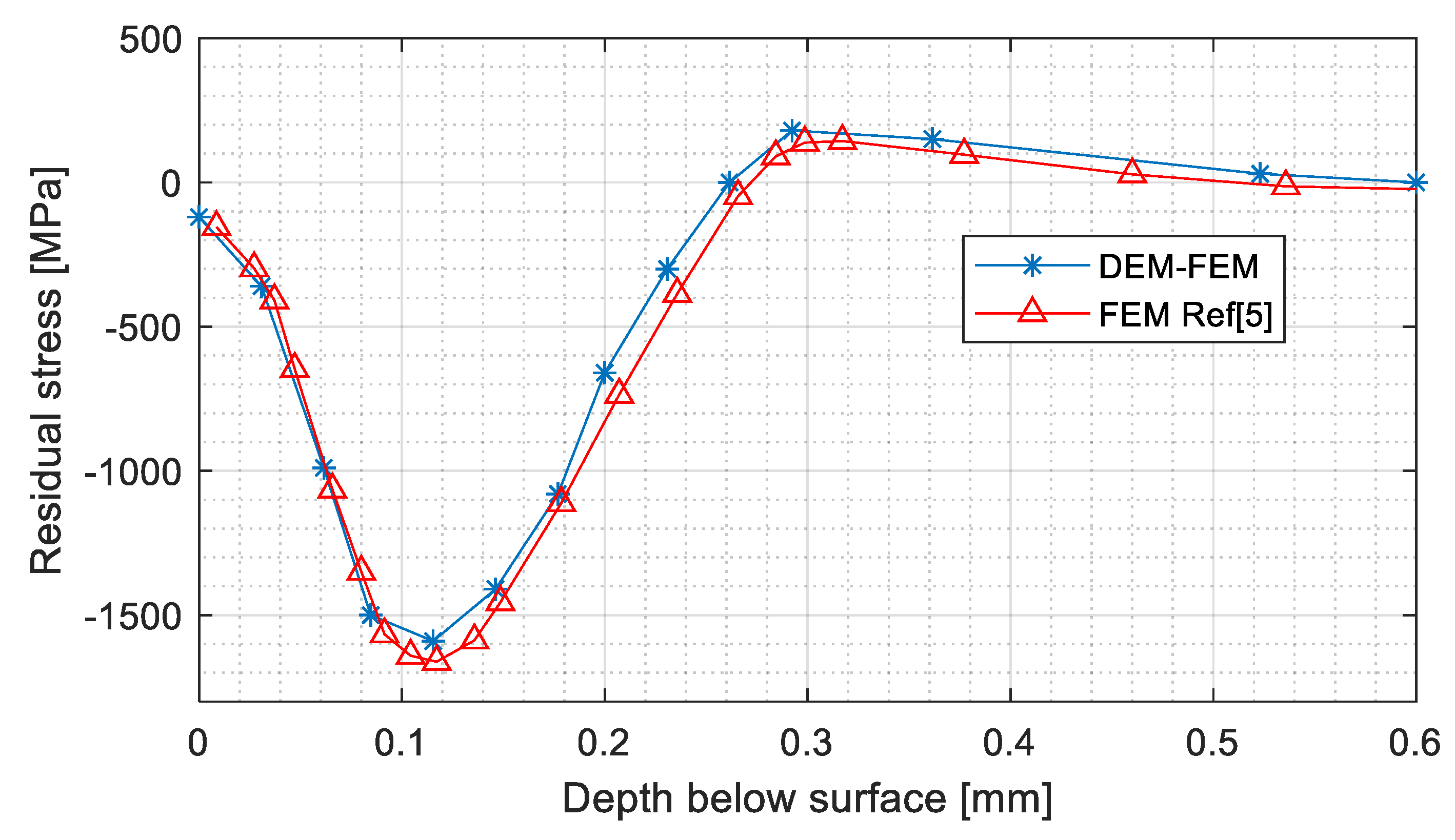
4.2. Numerical Verification of FE Model

A numerical investigation was carried out to verify the accuracy of the FEM model used in Step 1 to obtain the CoR, to be implemented in the DEM in Step 2.
An elastic impact simulation was first conducted in FEM, where the workpiece was assigned purely elastic properties. This simulation quantifies the fraction of impact energy lost without any plastic deformation of the workpiece. Then the same simulation was repeated but with an elastoplastic workpiece, so as to obtain the fraction of impact energy lost when plasticity is considered. The fraction of impact kinetic energy lost due to induced plastic strain (Ep) could be obtained by subtracting the fraction of energy restituted Erp in the simulation with elastoplastic workpiece from the fraction restituted Ere in a similar simulation with an elastic workpiece. This is expressed as:
Ep = EreErp

4.3. Discrete Element-Finite Element Coupled Simulation of Single-Shot

A single-shot simulation was carried out in Step 2 in the flowchart of Figure 3, with the same parameters as in Step 1, making use of the FEM calculated CoR, and facet sizes of 0.02 mm for all simulations in DEM. Facet sizes of 0.04 mm, 0.06 mm, and 0.08 mm are employed in the FEM at steps 4 and 5, with a unit cell target of thickness 1.29 mm, for imported force load of shots 0.3556 mm, 0.7 mm, and 1.0 mm diameter, respectively.
The respective mesh sizes chosen for the FEM analysis in the DEM-FEM combination is obtained by means of a single-shot impact which gives the same dent profile when carried out with FEM only. Contact forces were analyzed and exported per time step from EDEM to ANSYS for implicit analysis (Step 4). The equivalent stress trace is initialized in Step 5 for the pre-stressing of the workpiece, and finally, an explicit analysis is carried out to obtain the workpiece response to the imported force load. The total run time for the multiple implicit/explicit FEM analysis when coupled to DEM is about 10 min for a single-shot force load.

5. Numerical Results and Discussion

Table 3 displays the results obtained from a single-shot impact at different velocities with a workpiece assumed to be purely elastic. This results in different kinematic CoR (ere), from which the fractional energy restituted (Ere) are obtained by making use of Equation (4). The maximum contact force in FEM (FFEM) and the corresponding contact force in DEM for the same ere simulation produces a force correction factor at each impact velocity. Table 4 is a replica of Table 3, but for an elastoplastic workpiece material.
Table 3 and Table 4 resulted in Table 5, where the fractional plastic energy is obtained, and the equivalent CoR (er) is calculated.
From the results displayed in Table 3, Table 4 and Table 5, the values of fractional plastic energy obtained for single-shot simulations with ANSYS/Explicit dynamics at various shot velocities, were used to verify the accuracy of the model. As a check for the model accuracy, the expression:
0.8   E P E L     0.9
Ep/EL is satisfied for each simulation at the various shot velocities in Table 5, except for velocities 75 m/s and 100 m/s, where the deviations from the lower limit are within acceptable value of 5 percent reported and referenced by Sherafatnia et al. [38], and it has been highlighted in previous sections of this paper that 80 percent to 90 percent of energy lost by the shot is used for plastic deformation.
Figure 5 is generated from these tables, with an indication of a reduction in the kinematic CoR as the impact velocity increases. However, the calculated CoR (erc) does not follow the same trend as the kinematic CoR, but increases with velocity. This indicates that the kinematic CoR does not represent the increase in energy transmitted to the component at impact, with increase in the shot velocity.
Figure 6 shows the relationship between the contact forces in FEM and the equivalent force from DEM needed to obtain the same plastic deformation. It is observed that the difference in these two plotted quantities increases with the velocity of the shot. This will enhance the ability of shots with higher velocities to induced reasonable plastic strain, which is responsible for residual CRS. This could be the reason why former work by past researchers [28] could not be validated with available experimental results, as observed by [29], even at a velocity of 100 m/s, which is on a high side, for conventional shot peening.
It should be noted that this approach, which involves multiple system (implicit/transient structural and explicit/Autodyn) analysis in ANSYS, is a unique technique of indirectly applying a force load in ANSYS (explicit dynamics), which gives the CRS and PEEQ shown in Figure 7, Figure 8, Figure 9 and Figure 10. The results obtained are validated with results from the literature.
The resulting CRS and PEEQ profiles in Figure 7, Figure 8, Figure 9 and Figure 10 obtained with the present approach are in very good agreement with the numerical results for same single-shot simulations from recent works reported in the literature. The surface CRS, the maximum CRS, and its beneficial depth underneath the surface, the total depth of CRS, are in agreement with results from the literature. These numerical results used in validating the current approach are chosen because they were validated with experimental works, and the dynamic simulations of the single-shot were carried out with only FEM and not a coupled DEM-FEM.
A reduction of approximately 0.01 mm/mm in the maximum PEEQ generated with the present FEM-DEM approach, was observed specifically for 1.0 mm diameter shot in Figure 10; however, the depth is in good agreement of about 0.35 mm below the impact surface.

6. Conclusions

An energy-based sequential DEM-FEM model has been proposed for the evaluation of the response of a metallic workpiece to shot peening. A single-shot impact is specifically considered as the basis for multiple shots application in shot peening simulation. Therefore, a single-shot impact was investigated numerically by means of the EDEM commercial software coupled with the ANSYS finite element tool. This work highlighted the need for an energy-based approach to shot peening simulations where contact force/pressure from DEM is exported and applied directly in FEM, to avoid contact simulation in FEM. The application of exported force, instead of pressure in the FEM (Explicit dynamics) of the present work, eliminates the pitfalls in a previous DEM-FEM approach [28] to SP simulation, and resulted in time saved of up to 95 percent of the run time for a single-shot with only FEM.
The single-shot investigation carried out in this paper has revealed the following:
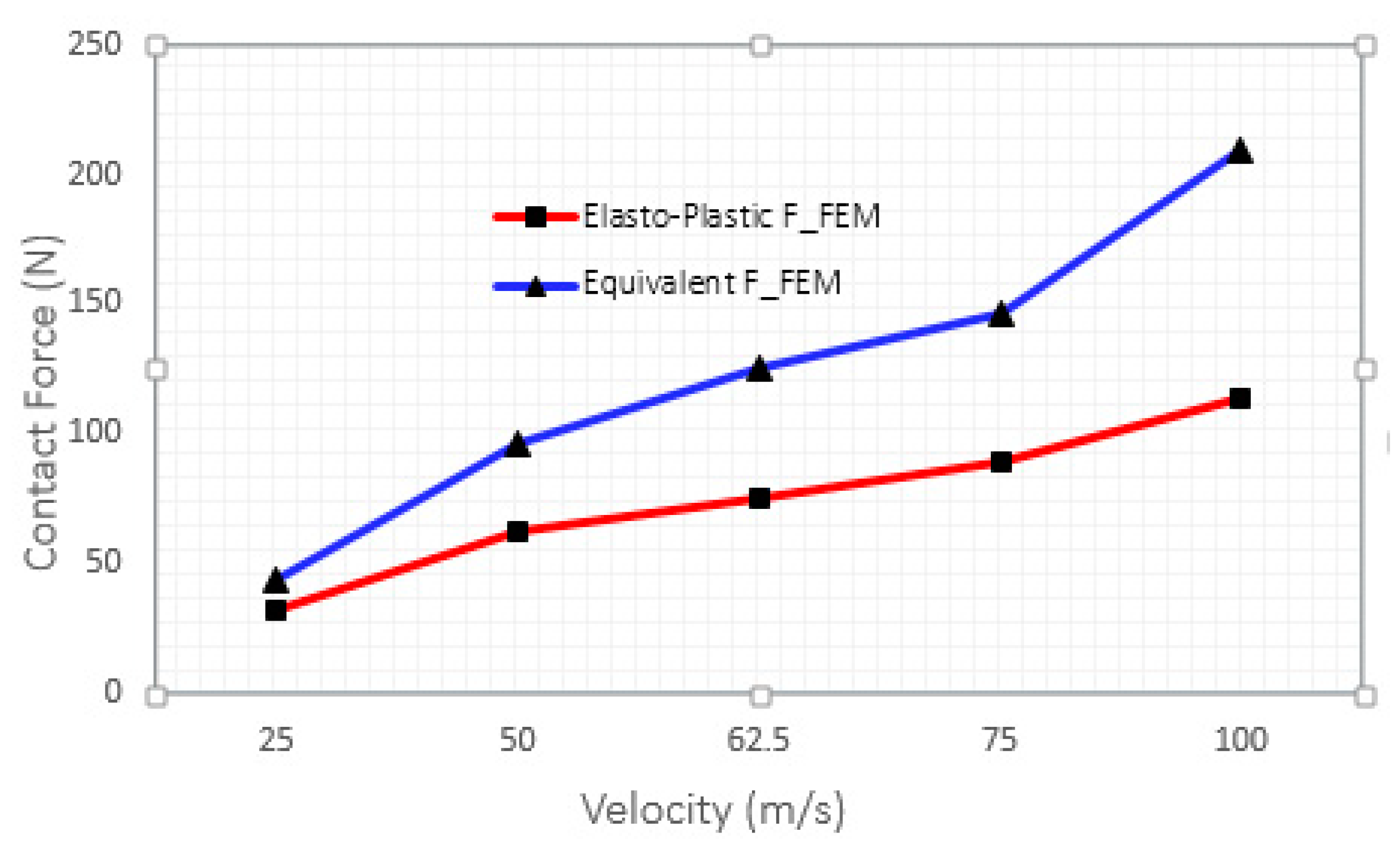
  • The reactive contact forces generated in impact simulation by FEM is not responsible for the plastic strain in the workpiece, but for the rebound of the shot. Thus an attempt to generate the same contact force as in the FEM using the same CoR in the DEM for subsequent application in FEM cannot yield the required result.
  • The kinematic CoR does not directly capture the energy lost by the shot, of which a greater portion (≥ 80 percent) is needed for induced CRS. Therefore, an energetic CoR should be utilized in establishing the needed force to be exported from DEM to FEM.
  • The need to verify the accuracy of the model based on the established and related theoretical background to the concept investigated, vis-à-vis a single-shot analysis which serves as the foundation for a more complex multiple shots stream.
  • The Hertz–Mindlin contact model cannot be used in DEM to generate the required contact force needed to produce the same plastic strain in FEM at a predetermined velocity. Thus, the Hysteretic–Spring contact model is a valuable tool for the purposed.
  • The prospect of utilising DEM as a tool in simplifying the approach to shot peening simulation when coupled to FEM, thus avoiding the complexity and the current inability in generating a realistic shot stream by FEM.
  • The simulation of a realistic SP process by a framework based on the current DEM-FEM approach is highly promising. Such a framework via the use of ANSYS workbench has the potential of incorporating the fatigue analysis of a load-bearing shot-peened component for benefits assessment. This will further enhance the SP process optimization, which is one of the aims of this research.

Author Contributions

Conceptualization, A.B.E.; Formal analysis, A.B.E.; Investigation, A.B.E.; Methodology—A.B.E.; Supervision, P.S.H.; Writing—original draft, A.B.E.; Writing—review & editing, P.S.H. and S.K.

Funding

This research was partially funded by Eskom under the Eskom Power Plant Engineering Institute Phase 2 Enabling and Funding agreement. The APC was not funded.

Acknowledgments

The authors would like to acknowledge the assistance of Esteq Engineering (Pty) Ltd. South Africa for facilitating the availability and use of EDEM software from Dem-solutions Edinburgh, UK, as well as the invaluable technical support provided by Jannie Pretorius of the Centre for the Advancement of Scholarship, University of Pretoria.

Conflicts of Interest

The authors declare no conflict of interest.

References

  1. Meguid, S.A.; Shagal, G.; Stranart, J.C. Finite element modelling of shot-peening residual stresses. J. Mater. Process. Technol. 1999, 92, 401–404. [Google Scholar] [CrossRef]
  2. Meguid, A.S.A.; Shagal, G.; Stranart, J.C.; Daly, J. Three-dimensional dynamic finite element analysis of shot-peening induced residual stresses Finite element modelling parametric analysis results of the single-shot model. Finite Elem. Anal. Des. 1999, 31, 4–6. [Google Scholar] [CrossRef]
  3. Guagliano, M. Relating Almen intensity to residual stresses induced by shot peening: A numerical approach. J. Mater. Process. Technol. 2001, 110, 277–286. [Google Scholar] [CrossRef]
  4. Schiffner, K.; Droste gen. Helling, C. Simulation of residual stresses by shot peening. Comput. Struct. 1999, 72, 329–340. [Google Scholar] [CrossRef]
  5. Shivpuri, R.; Cheng, X.; Mao, Y. Elasto-plastic pseudo-dynamic numerical model for the design of shot peening process parameters. Mater. Des. 2009, 30, 3112–3120. [Google Scholar] [CrossRef]
  6. Kobayashi, J.K.T. Estimation of residual stress distribution induced by shot peening. JTEKT Eng. J. 2011, 1008, 18–22. [Google Scholar]
  7. Bagherifard, S.; Ghelichi, R.; Guagliano, M. On the shot peening surface coverage and its assessment by means of finite element simulation: A critical review and some original developments. Appl. Surf. Sci. 2012, 259, 186–194. [Google Scholar] [CrossRef]
  8. Sanjurjo, P.; Rodríguez, C.; Peñuelas, I.; García, T.E.; Belzunce, F.J. Influence of the target material constitutive model on the numerical simulation of a shot peening process. Surf. Coat. Technol. 2014, 258, 822–831. [Google Scholar] [CrossRef]
  9. Eltobgy, M.S.; Ng, E.; Elbestawi, M.A. Three-dimensional elastoplastic finite element model for residual stresses in the shot peening process. Proc. Inst. Mech. Eng. Part. B J. Eng. Manuf. 2004, 218, 1471–1481. [Google Scholar] [CrossRef]
  10. Al-Obaid, Y.F. Shot peening mechanics-experimental and theoretical analysis. Mech. Mater. 1995, 19, 251–260. [Google Scholar] [CrossRef]
  11. James, M.N.; Hughes, D.J.; Chen, Z.; Hattingh, D.G.; Webster, P.J. Residual stresses and fatigue performance. 11th Int. Conf. Fract. 2005, ICF11 2005, 4, 2605–2610. [Google Scholar] [CrossRef]
  12. Gangaraj, S.M.H.; Guagliano, M.; Farrahi, G.H. An approach to relate shot peening finite element simulation to the actual coverage. Surf. Coatings Technol. 2014, 243, 39–45. [Google Scholar] [CrossRef]
  13. Miao, H.Y.; Larose, S.; Perron, C.; Levesque, M. An analytical approach to relate shot peening parameters to Almen intensity. Surf. Coat. Technol. 2010, 205, 2055–2066. [Google Scholar] [CrossRef]
  14. Meguid, S.A.; Shagal, G.; Stranart, J.C. 3D FE analysis of peening of strain-rate sensitive materials using multiple impingement model. Int. J. Impact Eng. 2002, 27, 119–134. [Google Scholar] [CrossRef]
  15. Hong, T.; Ooi, J.Y.; Shaw, B.A. A numerical study of the residual stress pattern from single-shot impacting on a metallic component. Adv. Eng. Softw. 2008, 39, 743–756. [Google Scholar] [CrossRef]
  16. Al-Hassani, S.T.S. Mechanical Aspects of Residual Stress Development in Shot Peening. Shot Peening 1981, 1, 583–602. [Google Scholar]
  17. Al-Hassani, S.T. Numerical Simulation of Multiple Shot Impact. In Proceedings of the 7th International Conference on Shot Peening, Warsaw, Poland, 28 September–1 October 1999; pp. 217–227. [Google Scholar]
  18. Mann, P.; Miao, H.Y.; Gariépy, A.; Lévesque, M.; Chromik, R.R. Residual stress near single-shot peening impingements determined by nanoindentation and numerical simulations. J. Mater. Sci. 2015, 50, 2284–2297. [Google Scholar] [CrossRef]
  19. Hong, T.; Ooi, J.Y.; Shaw, B. A numerical simulation to relate the shot peening parameters to the induced residual stresses. Eng. Fail. Anal. 2008, 15, 1097–1110. [Google Scholar] [CrossRef]
  20. Hirai, N.; Tosha, K.; Rouhaud, E. Finite Element Analysis of Shot Peening on the Form of a Single Dent. In Proceedings of the 9th International Conference on Shot Peening, Paris, France, 6–9 September 2005; pp. 82–87. [Google Scholar]
  21. Mori, K.-I.; Osakada, K.; Matsuoka, N. Rigid-plastic finite element simulation of peening process with plastically deforming shot. JSME Int. J. 1996, 39, 306–312. [Google Scholar] [CrossRef]
  22. Kobayashi, M.; Matsui, T.; Murakami, Y. Mechanism of creation of compressive residual stress by shot peening. Int. J. Fatigue 1998, 20, 351–357. [Google Scholar] [CrossRef]
  23. Zion, H.L.; Johnson, W.S. Parametric two-dimensional finite element investigation: Shot peening of high-strength steel. AIAA J. 2006, 44, 1973–1982. [Google Scholar] [CrossRef]
  24. Tong, X.; Li, Y.; Zhao, R.; Xiao, X.; Gao, G.; Liu, Y. Prediction of shot peen forming effects with single and repeated impacts. Int. J. Mech. Sci. 2018, 137, 182–194. [Google Scholar]
  25. Han, K.; Peric, D.; Crook, A.J.L.; Owen, D.R.J. A combined finite/discrete element simulation of shot peening processes—Part I: Studies on 2D interaction laws. Eng. Comput. 2002, 17, 593–620. [Google Scholar] [CrossRef]
  26. Jebahi, M.; Gakwaya, A.; Lévesque, J.; Mechri, O.; Ba, K. Robust methodology to simulate real shot peening process using discrete-continuum coupling method. Int. J. Mech. Sci. 2016, 107, 21–33. [Google Scholar] [CrossRef] [Green Version]
  27. Murugaratnam, K.; Utili, S.; Petrinic, N. A combined DEM-FEM numerical method for shot peening parameter optimization. Adv. Eng. Softw. 2015, 79, 13–26. [Google Scholar] [CrossRef]
  28. Bhuvaraghan, B.; Srinivasan, S.M.; Maffeo, B.; McClain, R.D.; Potdar, Y.; Prakash, O. Shot peening simulation using discrete and finite element methods. Adv. Eng. Softw. 2010, 41, 1266–1276. [Google Scholar] [CrossRef]
  29. Tu, F.; Delbergue, D.; Miao, H.; Klotz, T.; Brochu, M.; Bocher, O.; Levesque, M. A sequential DEM-FEM coupling method for shot peening simulation. Surf. Coat. Technol. 2017, 319, 200–212. [Google Scholar] [CrossRef]
  30. Soady, K.A.; Mellor, B.G.; Reed, P.A.S.; He, B.Y.; Morris, A. Effects of shot peening on short crack growth rate and resulting low cycle fatigue behaviour in low pressure turbine blade material. Mater. Sci. Technol. 2013, 29, 788–796. [Google Scholar] [Green Version]
  31. Wang, S.; Li, Y.; Yao, M.; Wang, R. Compressive residual stress introduced by shot peening. J. Mater. Process. Technol. 1998, 73, 64–73. [Google Scholar] [CrossRef]
  32. Gao, Y.K.; Yao, M.; Li, J.K. An analysis of residual stress fields caused by shot peening. Metall. Mater. Trans. A Phys. Metall. Mater. Sci. 2002, 33, 1775–1778. [Google Scholar] [CrossRef]
  33. Edward, A.B.; Heyns, P.S.; Pietra, F. Shot peening modeling and simulation for RCS assessment. Procedia Manuf. 2017, 7, 172–177. [Google Scholar] [CrossRef]
  34. Ahmad, M.; Ismail, K.A.; Mat, F. Impact models and coefficient of restitution: A review. ARPN J. Eng. Appl. Sci. 2016, 11, 6549–6555. [Google Scholar]
  35. Fathallah, R.; Inglebert, G.; Castex, L. Prediction of plastic deformation and residual stresses induced in metallic parts by shot peening. Mater. Sci. Technol. 1998, 14, 631–639. [Google Scholar] [CrossRef]
  36. Fathallah, R.; Inglebert, G.; Castex, L. Determination of shot peening coefficient of restitution. Surf. Eng. 2003, 19, 109–113. [Google Scholar] [CrossRef]
  37. Thornton, C. Coefficient of restitution for collinear collisions of elastic-perfectly plastic spheres. J. Appl. Mech. 2013, 64, 383–386. [Google Scholar] [CrossRef]
  38. Sherafatnia, K.; Farrahi, G.H.; Mahmoudi, A.H.; Ghasemi, A. Experimental measurement and analytical determination of shot peening residual stresses considering friction and real unloading behavior. Mater. Sci. Eng. 2016, 657, 309–321. [Google Scholar] [CrossRef]
  39. DEM-Solutions Inc. EDEM 2.7 User Guide 1; DEM-Solutions Inc.: Edinburge, UK, 2017; pp. 23, 135. Available online: www.dem-solutions.com (accessed on 30 October 2019).
  40. Farahani, H.K.; Ketabchi, M.; Zangeneh, S. Determination of Johnson–Cook plasticity model parameters for Inconel718. J. Mater. Eng. Perform. 2017, 26, 5284–5293. [Google Scholar] [CrossRef]
  41. Johnson, G.R.; Cook, W.H. Fracture Characteristics of three metals subjected to various strains, strain rates, temperatures and pressures. Eng. Fract. Mech. 1985, 21, 31–48. [Google Scholar] [CrossRef]
Figure 1. A typical residual stress profile due to shot peening.
Metals 09 01183 g001
Figure 2. Impact of a single shot with mass m, at the surface of a workpiece showing the restitution of the shot after impact.
Metals 09 01183 g002
Figure 3. Data Flow between DEM and FEM.
Metals 09 01183 g003
Figure 4. Single-shot simulation model in 3D mesh, showing residual stress map on workpiece surface after rebound.
Metals 09 01183 g004
Figure 5. A plot of the Coefficient of Restitution (CoR) obtained using the Finite Element Method (FEM) and the calculated CoR that is implemented in the Discrete Element Method (DEM), against shot velocities.
Metals 09 01183 g005
Figure 6. A plot of the contact force in FEM and the equivalent contact force from the DEM needed for plastic deformation in FEM at various shot velocities.
Metals 09 01183 g006
Figure 7. Residual stress profile for a single shot of 0.3556 mm diameter at 70 m/s onto a target made of Inco718. Showing the current DEM-FEM result and FEM result recreated from the literature [29].
Metals 09 01183 g007
Figure 8. Residual stress profile for a single shot of 0.7 mm diameter at 50 m/s onto a target made of AISI 4340. Showing the current DEM-FEM result and FEM result recreated from the literature [5].
Metals 09 01183 g008
Figure 9. Residual stress profile for single-shot of 1.0 mm diameter at 50 m/s onto a target made of AISI 4340. Showing the current DEM-FEM result and FEM result recreated from the literature [5].
Metals 09 01183 g009
Figure 10. Equivalent strain profiles generated in 4340 steel impacted at 50 m/s by a single 1.0 mm diameter shot with coefficient of friction 0.1. Showing the current DEM-FEM result and FEM result recreated from the literature [5].
Metals 09 01183 g010
Table 1. Mechanical properties of shots and Targets (workpieces).
PropertyWorkpiecesShots
Inco718 [40]AISI 4340 [5]Cast Steel [5]CW-14 [29]
Elastic modulus (GPa)177.00205.0210210
Density (kg/m3)8220.0780078007800
Poisson’s ratio0.27300.290.280.30
Yield Strength (MPa)1036.01511RigidRigid
Tensile Strength (MPa)1240.01864n/an/a
Table 2. Johnson and Cook (JC) Materials constants and parameters adopted for Equation (12) in the FEM simulations.
MaterialA (MPa)B (MPa)CnmTM (K) ε ˙ 0   ( s 1 )
AISI 4340 [5]1498943.80.01400.2601.0317931.0
Inconel718 [40]1108699.00.00850.51891.015931.0
Table 3. Elastic run for Shot 0.3556 mm.
V1 (m/s)V2 m/sereEreFFEM (N)FDEM (N)Force Factor (FF)
2523.600.94440.891947.7530.8361.548
5046.1150.92230.8506106.47670.051.520
62.556.950.91120.8303146.72690.621.619
7567.4250.8990.8082167112.241.487
10088.090.88090.7759248.31156.621.585
Table 4. Elastic-plastic Run Shot 0.3556 mm.
V1 (m/s)V2 m/sereErpFFEM (N)FDEM (N)Force Factor (FF)
2511.3730.45500.206431.84321.331.492
5018.7770.37550.141062.03944.931.381
62.522.1030.35360.125074.73951.821.292
7524.7500.33000.108988.72070.621.256
10030.3110.30300.0918114.30395.921.192
Table 5. A combined analysis of Table 3 and Table 4 for Ep and equivalent contact force (FFEM).
V1 (m/s)EL = 1 − Erp e r c = 0.8 E L Ep = EreErpFDEM (N)Ave. FFFFEM (N)Ep/EL
250.79360.79680.685528.6361.5206544.100.8638
500.85900.82890.709666.1331..450095.890.8261
62.50.87500.83660.705386.261.4550125.510.8060
750.89110.84430.6993106.451.3715145.990.7848
1000.90820.85240.6841151.001.3885209.660.7533

