Article

The Influence of Pre- and Post-Heat Treatment on Mechanical Properties and Microstructures in Friction Stir Welding of Dissimilar Age-Hardenable Aluminum Alloys

1
School of Materials Science and Engineering/Herbert Gleiter Institute of Nanoscience, Nanjing University of Science and Technology, Nanjing 210094, China
2
State Key Laboratory of Advanced Design and Manufacturing for Vehicle Body, Hunan University, Changsha 410082, China
*
Authors to whom correspondence should be addressed.
Metals 2019, 9(11), 1162; https://doi.org/10.3390/met9111162
Submission received: 27 September 2019 / Revised: 23 October 2019 / Accepted: 25 October 2019 / Published: 28 October 2019
(This article belongs to the Special Issue Characterization of Welded Joints)

Abstract

:
An Al-Mg-Si alloy 6061 and an Al-Zn-Mg alloy 7A52 were joined by friction stir welding successfully. Pre- and post- heat treatment were employed to improve the strength of the weld. The results show a best weld joint with the lowest hardness of 100 HV in 6061 matrix, being achieved by post-solid-solution and subsequent two-stage artificial aging for the whole weld joint of the 7A52 and 6061 solid solution. Under this condition, the weld nugget zone (WNZ) is stronger than 6061 matrix but it has lower hardness than 7A52 matrix. The hardness of WNZ is contributed by the combination of η′ and L precipitates, dynamically changes along with the ratios between the number of η′ and L precipitates. The higher the number density of η′ precipitates, the hardness of WNZ is closer to that of the 7A52 matrix. Otherwise, the higher number density of L precipitates, the hardness of WNZ is closer to that of 6061 matrix. The coexistence of η′ and L precipitates is a direct result from the mixture of 7A52 and 6061 alloys achieved by stirring. Precipitates identification and composition analysis reveal a dynamic WNZ with constituent transition in hardness and composition.

Graphical Abstract

1. Introduction

As high strength aluminum alloys, Al-Zn-Mg alloys of the 7000 series family and Al-Mg-Si alloys of the 6000 series family are widely used in the defense, aerospace, automotive, and structural applications. In these heat-treatable alloys, Mg combines with Zn or Si (Cu) to form a large number of strengthening precipitates during aging, such as the metastable precursors of η-MgZn2 [1,2] and β″-Mg5Si6, L, and/or Q-phase [3,4], contributing to the high strength of these alloys. Presently, there is great interest in these alloys to advance strengthening to further reduce the weight of structures in high-speed train, aircraft, and other applications. However, to join components that were made by these alloys is a large challenge in assembly, because of the sensitivity of the strengthening metastable precipitates in these alloys to thermal cycles introduced by traditional fusion welding. The strength of the weld would be significantly reduced due to precipitates coarsening in the heat affected zone (HAZ) [5]. As with the fusion welding joint of Al-Mg-Si alloys, the strength of the HAZ is even lower than that of the weld zone, due to over-aged HAZ resulting from heat input. Moreover, the conventional fusion welding processes are not suitable for dissimilar welding applications, due to the different thermodynamic behavior of dissimilar materials.
Friction stir welding (FSW) is an effective method for joining many combinations of dissimilar materials at the solid state, being pioneered and practiced by Wayne Thomas in 1991 [6]. As a new family of solid-state joining techniques, benefitting from the decreasing of heat input and the introduction of deformation during FSW, the joint might be free from the dendritic structure typical of a fusion-weld joint, and it has finer microstructures and better mechanical properties than the respective fusion welding joint. These welding processes have been successfully applied to join dissimilar aluminum alloys [7,8,9,10,11,12,13]. In the literatures, investigators have paid more attention to study the effect of FSW parameters on microstructures, mechanical properties, and defects formation [7,9,11,12,13,14,15,16,17,18,19,20,21,22,23,24]. Researchers found that FSW parameters, such as tool design, tool rotation and traverse speed, depth of tool plunge, angle of tool tilt, tool pin offset, and welding gap, etc., may lead to defect formation, if they are not selected properly [8,25,26].
Beyond a weld joint without defects, engineers strive to pursue higher mechanical properties. Thus, researchers need to understand the microstructural evolution and the underlying physics of FSW. For precipitation-hardened Al alloys, such as 6000 and 7000 series, the thermos-mechanical process of FSW results in the change of precipitate structure, size, distribution, and density in different zones [27]. Generally, this change is negative for the strength of the FSW joint. In the nugget zone of the weld (WNZ), the pre-existed hardening precipitates will dissolve due to the sufficient high temperature that is generated during FSW. The region outside of the WNZ is termed the thermo-mechanical affected zone (TMAZ), where precipitates will be sheared or surrounded by dislocations introduced by severe plastic deformation. Outside of the TMAZ is the heat affected zone (HAZ), in which precipitates coarsen and transform into the stable partner, which makes HAZ over-aged and soften. Obviously, an important reason for the drop of strength in FSW joint is the loss of strengthening precipitates. Researchers naturally adopted post-heat-treatment to reform the strengthening precipitates. The effect of post-weld heat treatment on FSW joints of dissimilar Al alloys were investigated [28,29,30,31], they found that, after post-weld heat treatment, the strength of the weld can be improved if there are new precipitates forming during post heat treatment, the location and mode of fracture under tension are completely different from the as-weld joints [32,33,34,35]. However, not all post-weld heat treatment is effective. Mahoney et al. found that the post-weld T6 aging treatment would not help in the improvement of the mechanical properties of FSW joints of AA7075-T651 [36]. Sullivan and Robson even found that post weld heat treatment (T7 temper) coarsened nano-sized precipitates in matrix, WNZ, and TMAZ of FSW AA7449 joints, which results in the decrease of hardness in these area [37]. The above conflicting results revealed that the aging conditions of the as-received materials and the precipitates in the as-weld sample should be considered before the application of post-weld heat treatment.
In this work, the effect of pre- and post- heat treatment on the hardness of the weld joints between two technologically important age hardenable Al alloys (7A52 and 6061) was investigated from the point view of microstructural evolution at different scales. Moreover, the underlying physics of precipitation kinetics was revealed by high-resolution transmission electron microscopy (HRTEM) (Thermo Fisher Scientific, Waltham mass, Massachusetts, USA). A new strategy of two-stage aging was proposed to restore precipitation strengthening in the weld based on the above.

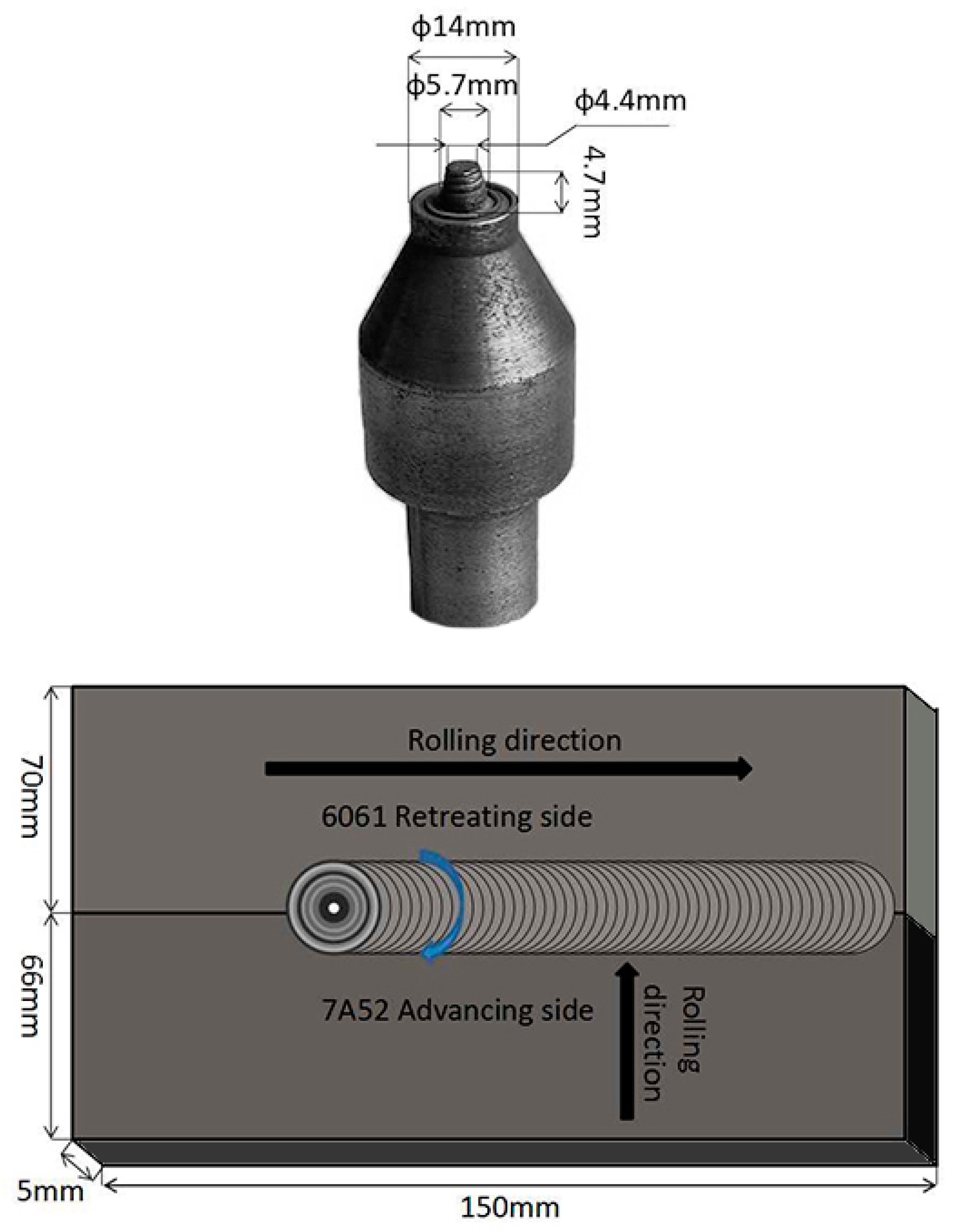
2. Material and Experimental Details

Two technologically important age hardenable Al alloys, 7A52 and 6061, were employed in this study. These alloys were received in the form of 5 mm thick sheets. The chemical compositions of these alloys were determined, as listed in Table 1.
The FSW were carried out while using a commercial gantry type FSW machine (FSW-LM-025-2030,Jiangsu Ruicheng Machinery Co., Ltd, Yixing, China) with position control mode. The friction stir butt welds between the rolled plates of 7A52 and 6061 aluminum alloys were obtained at a welding speed of 90 mm/min. and rotational speed of 500–700 rpm, while employing a single pass welding procedure. The plates were held firmly, covered by thermal insulation board, and then preheated at 150 °C for 2 h before welding. Figure 1 shows the welding direction. The FSW tool was made of die steel and had flat shoulder with truncated conical pin having anticlockwise thread of 1 mm pitch. Figure 1 demonstrates the profile of the FSW tool. The depth of shoulder plunge was kept 0.2–0.3 mm from workpiece surface.
Before welding, the as-received alloy plates were treated as solid solution (SS): 475 °C for 1.5 h for 7A52 alloy and 535 °C for 1 h for 6061 alloy, or further treated as T6-state after SS: aging at 120 °C for 24 h for 7A52 alloy and 180 °C for 30 min. for 6061 alloy. The SS treatment was carried out in a box-type furnace and the age treatment was carried out in oil bath. The SS treated samples and T6 treated samples were joined by FSW, respectively. After welding, different heat treatments were employed to strengthen the weld joint. They were solid solution treated again or aged directly. The parameters in the post-heat-treatment are the same as the pre-heat treatment. If the two side of the weld joint were aged respectively, one side being immersed into hot oil and the other side is uncovered.
The visually sound joints were selected by visual inspection or while using optical microscopy for hardness test and microstructure analysis. Microhardness variations across the joint were measured on a HMV-G 21DT Micro Vickers Hardness Tester with an applied load of 100 g and a holding time of 10 s, each value was obtained by averaging at least five successive measurements. With the help of indentation of the hardness test, the specimens for microstructure characterization were accurately extracted from specific zones. A focal-ion beam (FIB)/SEM system (Carl Zeiss Auriga 45-66, Jena, Germany) was employed to examine grains of FSW joints in electron back-scattered diffraction (EBSD) (Oxford Instruments, Oxford, UK) mode. An FEI Titan G2 60-300 transmission electron microscope (TEM) (Thermo Fisher Scientific, Waltham mass, Massachusetts, USA) was used to examine the precipitates in different zones. Specimens for EBSD were prepared by mechanical polishing and then electrochemical polishing in a solution mixed of 10% perchloric acid and 90% ethyl alcohol at the voltage of 15 mV and at the temperature of −30 °C. The specimens for TEM were prepared as the following: the specimens were thinned down to 100 µm and then punched to form a disc with the diameter of 3 mm. These discs were mechanically ground and subsequently electro-polished while using a twinjet unit (TJ100-SE produced by LEBOscience) with an electrolyte of 30% nitric acid in methanol at −25 °C and 20 V. The specimens for microstructure examination were sectioned from the transverse section perpendicular to the welding direction, because the transverse section comprises all of the zones with different microstructures and associated mechanical properties.

3. Results

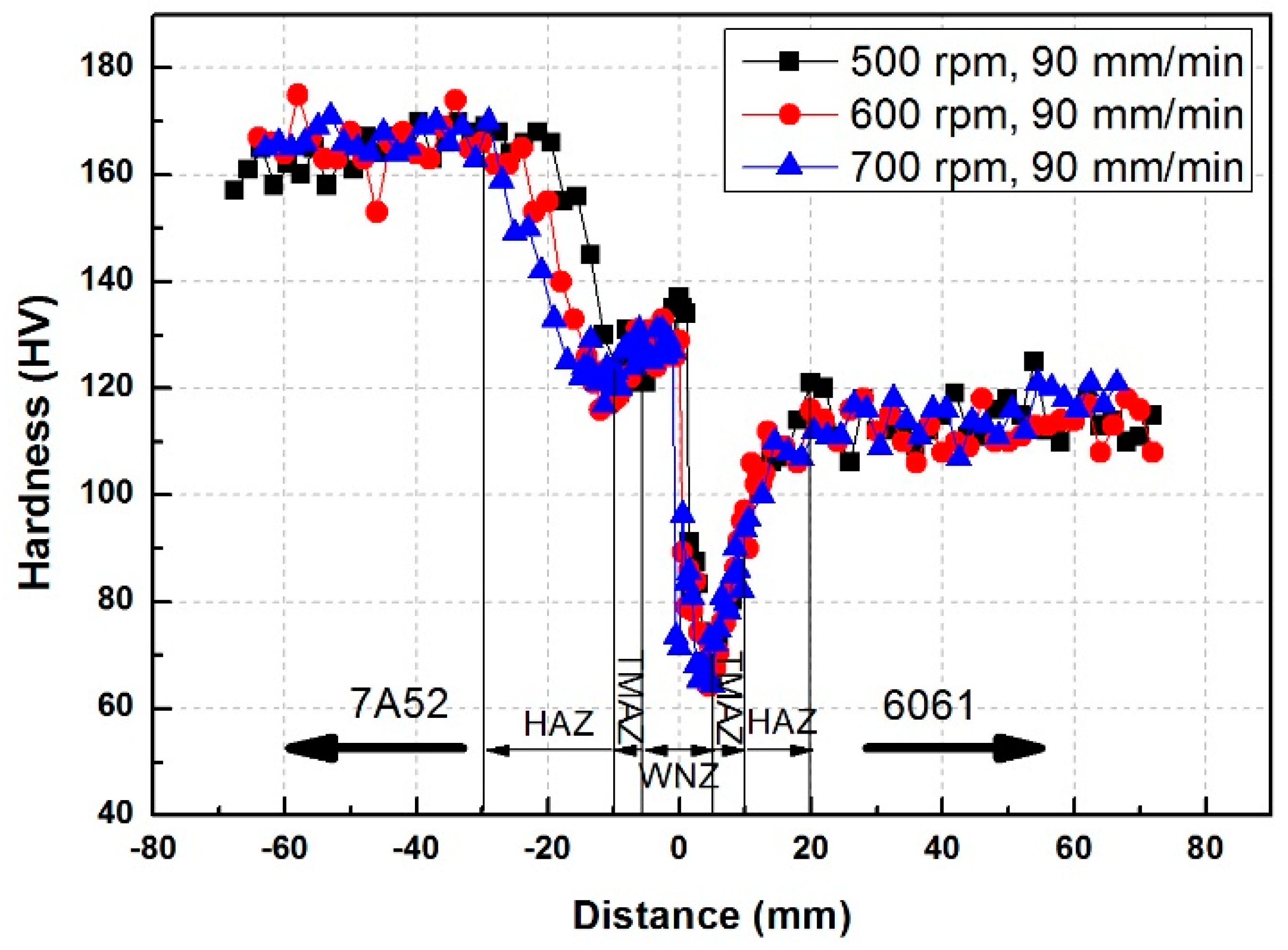
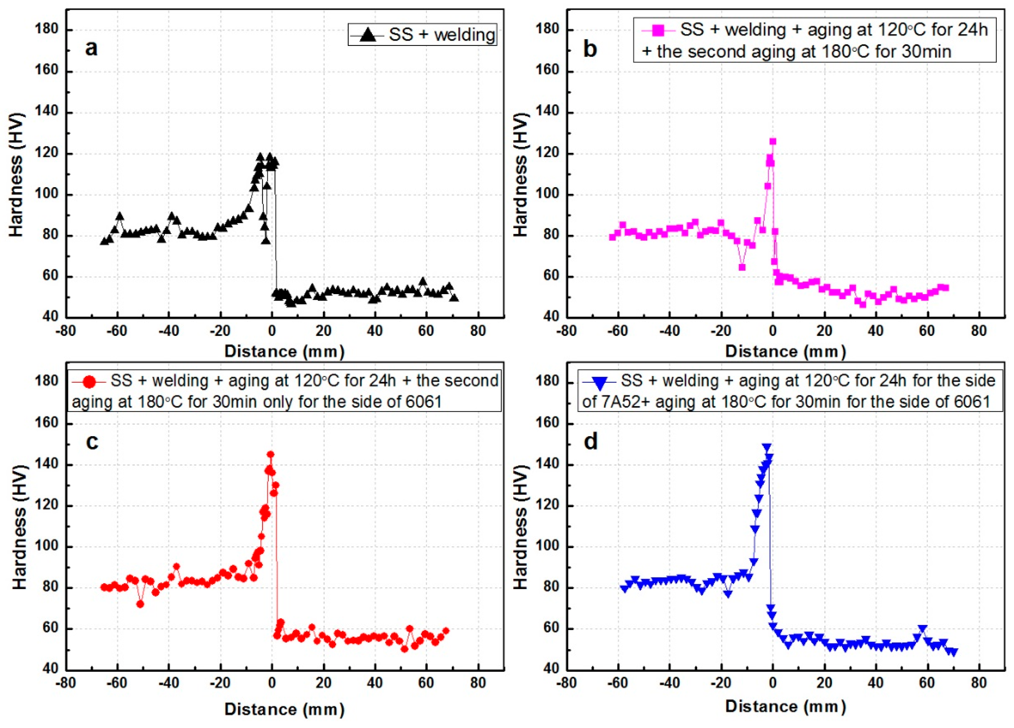
3.1. Hardness Evolution with Different Heat Treatment

The 7A52 and 6061 Al alloys were T6-heat-treated, respectively, with the average hardness of 165 HV and 115 HV, and then joined by FSW. Figure 2 presents the hardness variation across the weld joint along the central line of the transverse section with different rotational speeds, where the different zones are indicated. The hardness curve of FSW joint is asymmetrical with respect to the weld center. The lowest hardness (62 HV) appears near the center of the WNZ on the 6061 side, the hardness gradually rises from WNZ to the TMAZ, to the HAZ, till the 6061 matrix, or to the center line on the opposite side. A sudden increase in hardness occurs at the center line from 98 HV on the 6061 side to 138 HV on the 7A52 side. Subsequently, the hardness drops slowly to approximately 120 HV in the TMAZ on the 7A52 side, and the hardness afterwards increases slowly from HAZ to the 7A52 matrix. As shown in Figure 2, the width of HAZ on the 7A52 side is affected by the rotational speed, the higher rotational speed selected, the wider HAZ formed.
After solid solution, the 7A52 and 6061 Al alloys were joined by FSW at the rotation speed of 600 rpm, and post-aging was then employed; Figure 3a presents the hardness variation across the weld joint along the central line of the transverse section. It is very interesting that the WNZ and HAZ is stronger than the matrix on the 7A52 side, although a narrow area with low hardness near 78 HV was found to be in TMAZ, as shown in Figure 3a. On the 6061 side, the hardness keeps constant from the WNZ to the matrix. After welding, aging treatment was employed with three different heating methods, as shown in Figure 3b–d; the hardness change occurs on the 7A52 side, not on the 6061 side. After post-aging, on the 7A52 side, the hardness in TMAZ significantly increased, the highest hardness was tested in WNZ, and then successively drops from WNZ to the matrix, via TMAZ and HAZ. Aging 7A52 and 6061 alloys separately obtained the highest hardness of 150 HV in WNZ on the 7A52 side (Figure 3d). Unfortunately, the hardness of the matrix is too low after welding, even cannot be increased after post-aging, because the matrix of 7A52 and 6061 were over aged during pre-heating at 150 °C for 2 h before welding.
When considering the negative effect of pre-heating on the hardness of the matrix, solid solution treatment was employed after welding and before post-aging. The solid solution temperature of 6061 alloy is higher than that of the 7A52 alloy, the 7A52 side was solid-solution treated first at 475 °C for 1.5 h, and then the 6061 side was treated at 535 °C for 1 h. Affected by the thermal transmission, precipitation occurs in the 7A52 side during the subsequent solid solution of the 6061 side. Hence, after post-solid-solution-treatment, the hardness of 7A52 matrix (near 120 HV in Figure 4a) is higher than that of the solid solution treated 7A52 alloy (about 80 HV). As shown in Figure 4a, after the post-solid-solution treatment, the hardness on both side of the central line keeps constant from the WNZ to the matrix. However, the hardness on the 7A52 side is much higher than that on the 6061 side and an abrupt increase appears near the central line from 6061 side to 7A52 side. After the subsequent post-aging, as shown in Figure 4b–d, the hardness of the weld joint was significantly improved, and still kept steady on both sides without signs of softening. With different heating procedures for post-aging, different hardness is achieved on both sides. As is well known, the strength of a weld joint is dependent upon the weakest region. Hence, the study focused on how to improve the lowest hardness. From Figure 4, it can be seen that the weld joint undergoing two-stage artificial aging (SS + welding + SS + aging at 120 °C for 24 h + the second aging at 180 °C for 30 min.) has the lowest hardness of about 100 HV on the 6061 side (Figure 4b), higher than that obtained by other post-aging treatments (Figure 4c,d), meanwhile the hardness of the 7A52 side is approximately 140 HV (Figure 4b). More importantly, the hardness evolution from the 7A52 side to 6061 side is gradual in Figure 4b–d, as opposed to the sudden shift seen in Figure 3 and Figure 4a. This smooth change in hardness benefits the weld joint in stress concentration during service.

3.2. Microstructures

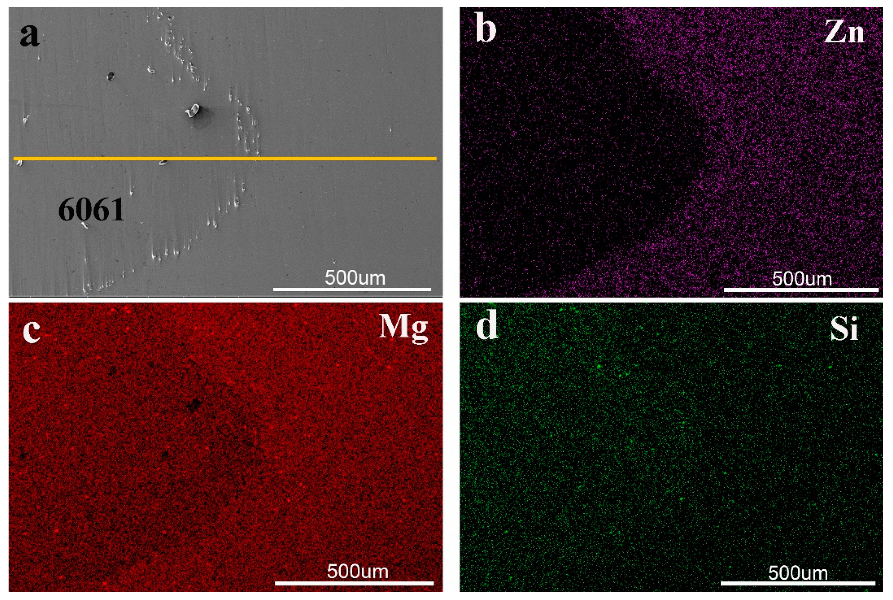
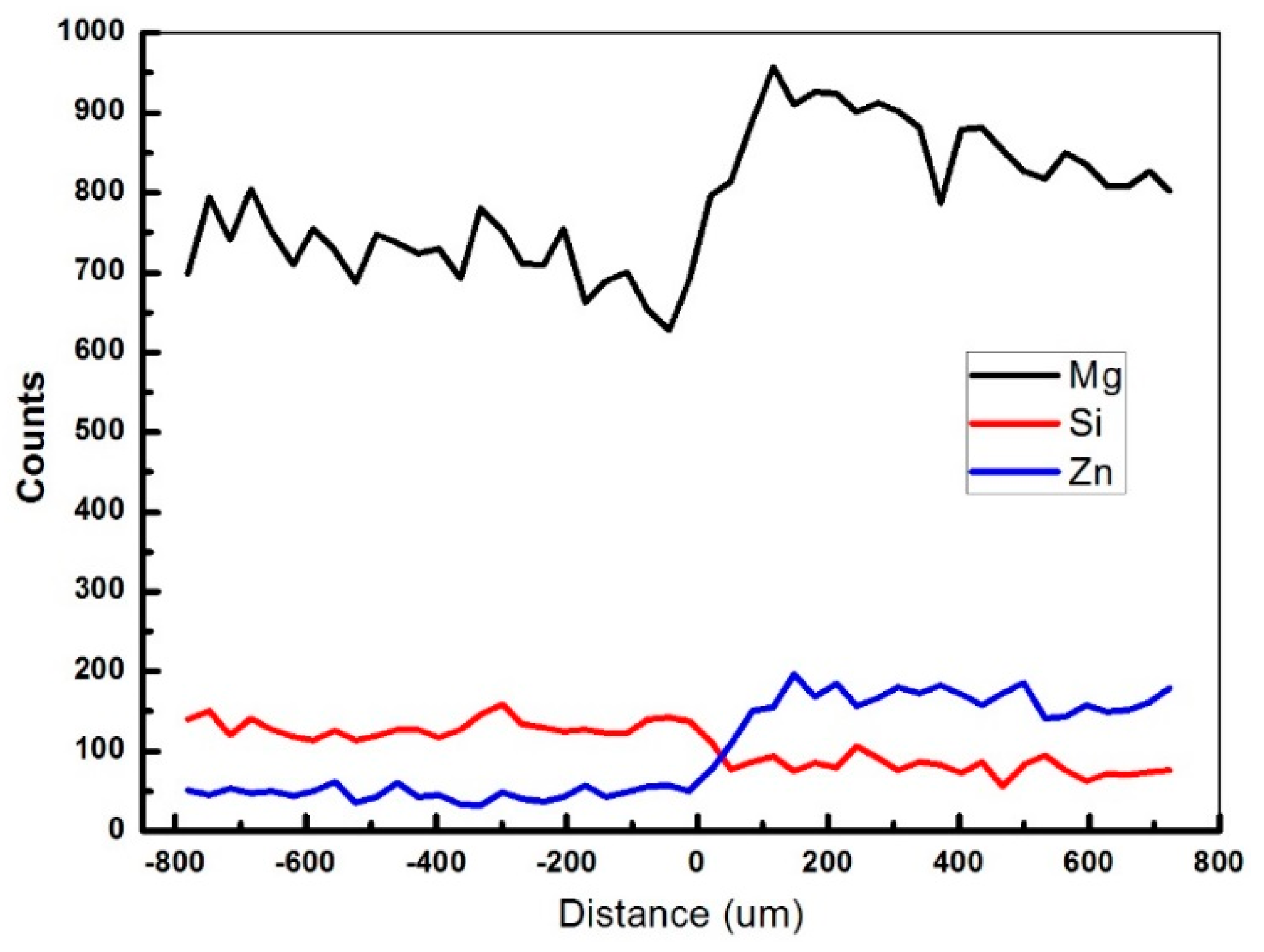
3.2.1. Alloying Elements Redistribution in WNZ
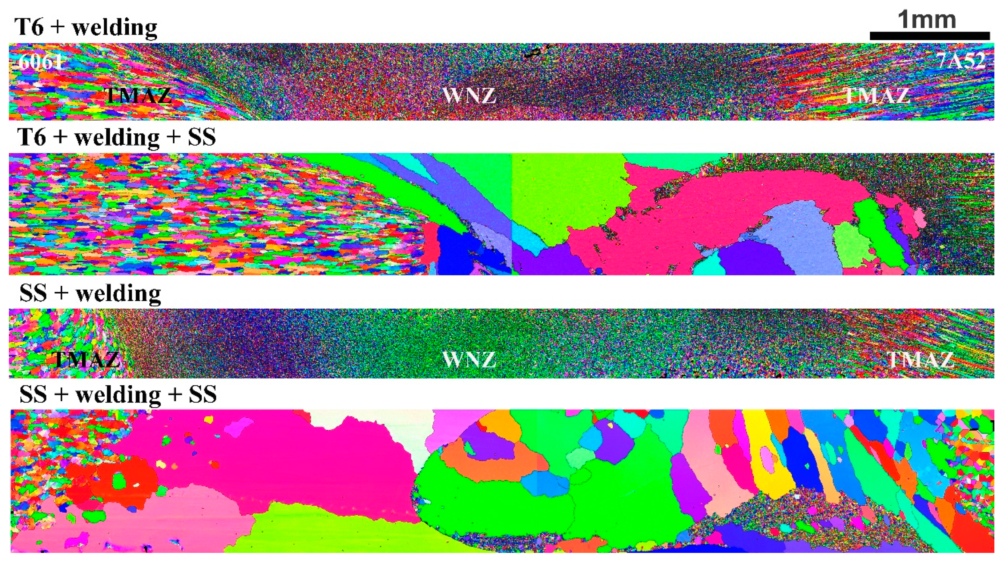
Figure 5 shows the second electron image and EDS mappings of the main alloying elements in two adjacent grains near the central line in the post-solid-solution treated sample corresponding to Figure 4a. As seen from Figure 5a, there are obviously a large number of the second phases at the grain boundary between these two grains. Figure 5b–d show the grains are composed of Zn, Mg, and Si, and Figure 6 shows that the right grain has a higher level of Mg and Zn, but a lower level of Si. In other words, the composition of grains in WNZ has been changed and the elements diffusion occurred during stirring or post-solid-solution. The line scanning in Figure 6 reveals the content of alloy elements is higher gradually from 6061 side to 7A52 side, which is the basic of the gradual increase of precipitation hardening in WNZ after post-aging from 6061 side to 7A52 side, as shown in Figure 4b–d.

3.2.2. Grains

Figure 7 shows the orientation maps of grains in and adjacent to different zones locating by hardness measurement. The left is 6061 alloy and the right is 7A52 alloy. The as-rolled 6061 alloy plate comprises of recrystallized approximately equiaxed grains, and the as-rolled 7A52 alloy plate is composed of deformed elongate grains. After welding, grains in WNZ are equiaxed with a mean size of 5 µm, resulting from dynamic recrystallization, independent of the pre-heat-treatment. In TMAZ on the advancing side (6061), the as received equiaxed grains were severely elongated, and bended too far along the direction of metal flow. On the other hand, in TMAZ on the retreating side (7A52), there are more equiaxed recrystallized grain when compared with the 7A52 matrix. On the retreating side, it was found that the transition of grains is pretty smooth from TMAZ to WNZ, in comparison to the advancing side. The width of the TMAZ on both sides is approximately 1 mm.
After post-solid-solution treatment, abnormal grain growth was found in both the WNZ for (T6 + welding + SS) sample and (SS + welding + SS) sample; this phenomenon has also been reported in literatures [32,33]. Obviously, the pre-treatment has significant influence on the region of abnormal grain growth. In (T6 + welding + SS) sample, abnormal grain growth only occurred in WNZ, but in (SS + welding + SS) sample, abnormal coarse grains were found in WNZ and TMAZ. The size of these coarse grains is of the order of millimeter or sub-millimeter.

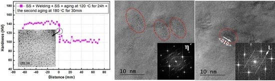
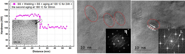
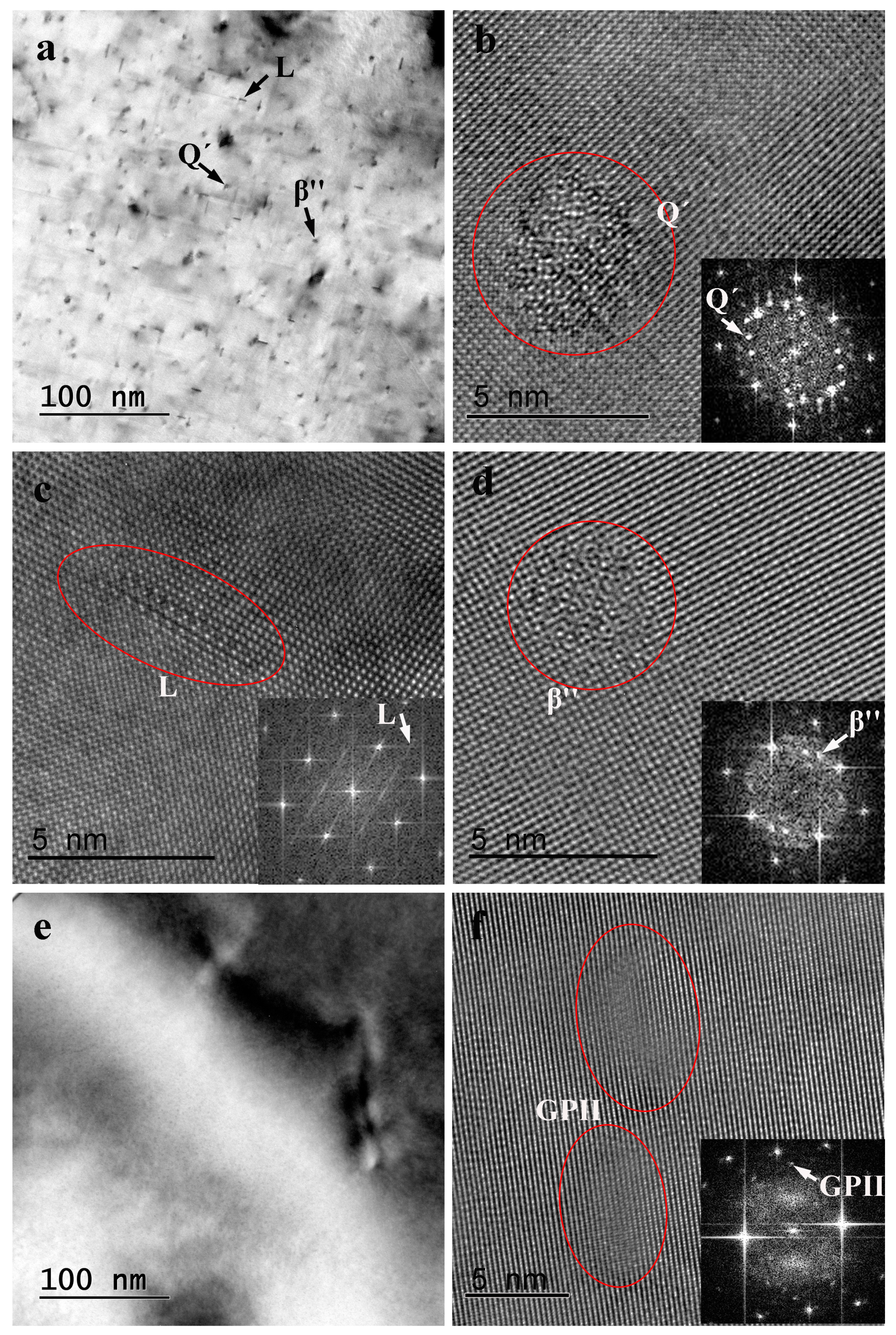
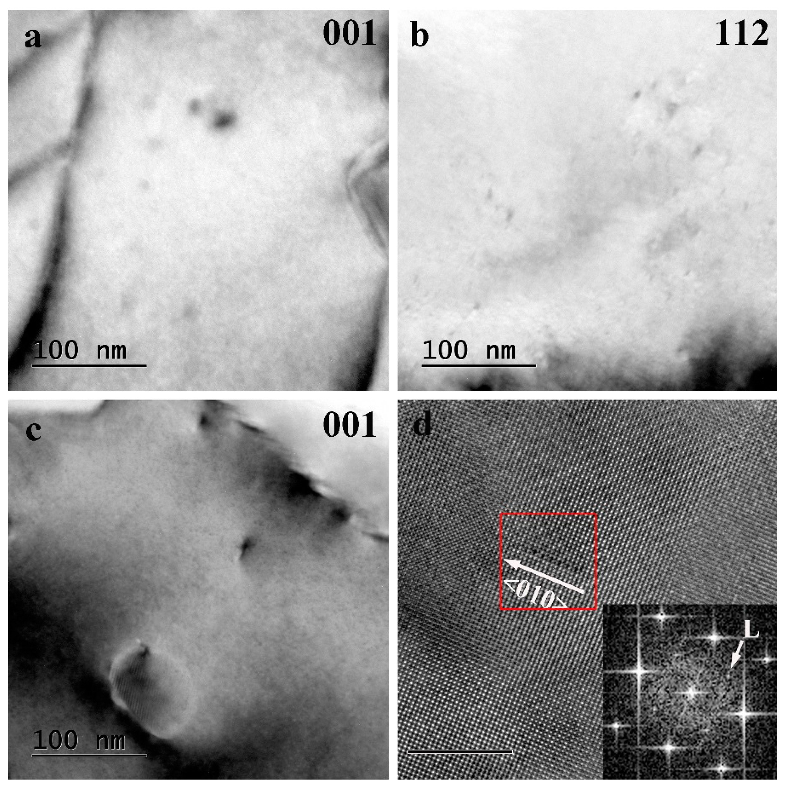
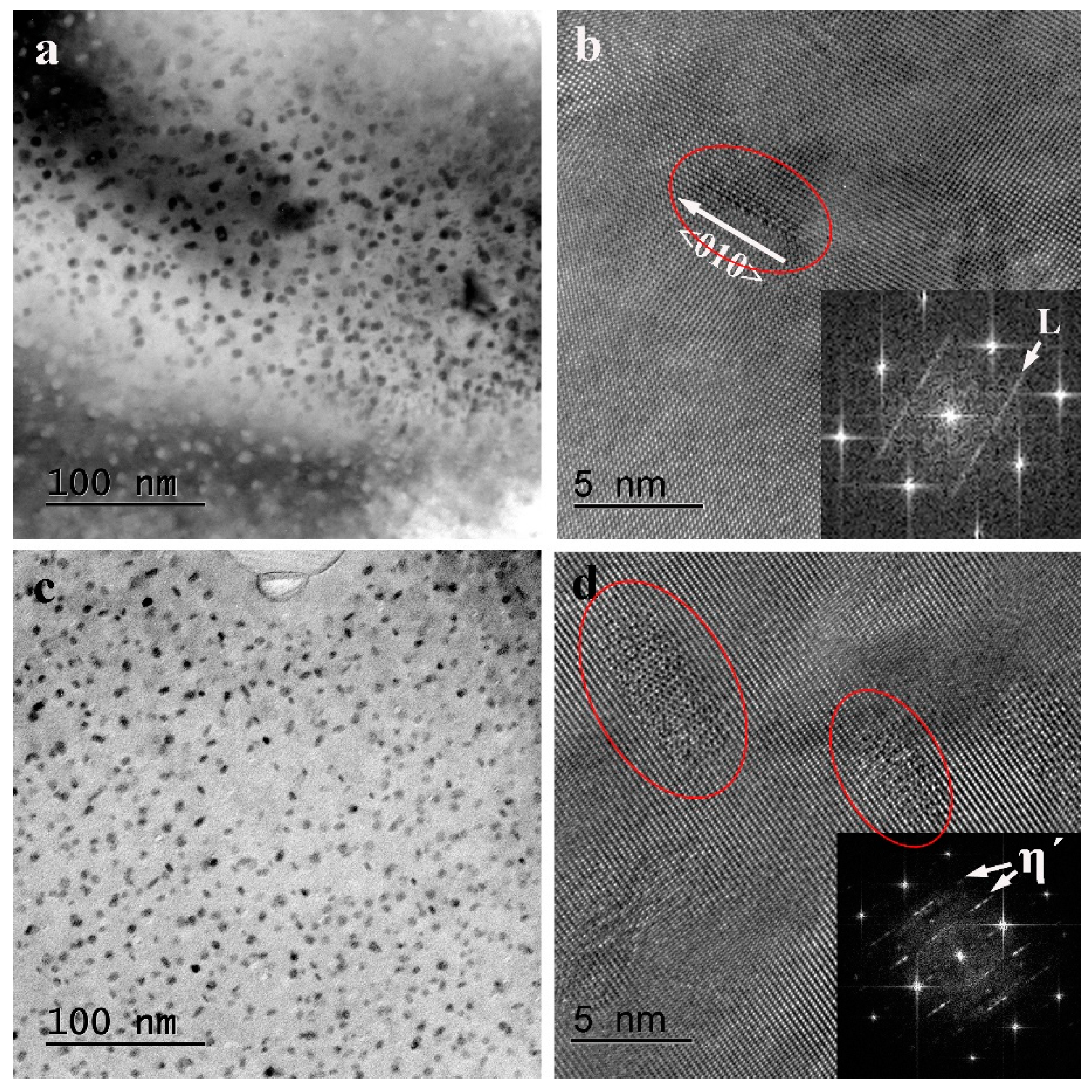
3.2.3. Microstructures in the Interior of Grains

Figure 8 shows the TEM bright-field images and high-resolution TEM (HRTEM) images of intragranular precipitates in the T6-treated matrix. In the 6061 alloy, all of the images were acquired in <001>Al directions, there are three types of precipitates observed: L phase, β″ phase, and Q′ phase. The overview of known precipitates in the Al-Mg-Si alloy is listed in Table 2 in Ref. [3]. These precipitates were distinguished from morphology (Figure 8a) or with the help of HRTEM images and the corresponding Fast Fourier Filtering transform (FFT) patterns (Figure 8b–d). The needle-like precipitates were identified as the β″ phase (Figure 8d), the lath-like precipitates with the cross-section elongated along <510>Al were the Q′ phase (Figure 8b), or with the cross-section elongated along <001>Al were the L phase (Figure 8c). The L phase is a precursor of Q′ phase. The addition of Cu has suppressed the formation of β″ by the formation of Cu-containing precipitates (L and Q′), which result in the coexistence of lath-like and needle-like precipitates. In 7A52 alloy, all of the images were taken along <112>Al orientations, where a large number of GPII zones can be observed in Figure 8d. Two crystallographic orientations, <110>Al and <112>Al, are most suitable to identify disc-like precipitates in Al-Zn-Mg alloys, but along <112>Al more structural details can be revealed for the η′-phase [38,39]. As shown in Figure 8d, the disc-like GPII zones are fully coherent with the Al matrix, composed of Zn-rich layers on the Al-{111} atomic planes. The profiles of GPII zones are presented by stress field contrast, resulting from atomic size difference between Zn, Mg, and Al.
Figure 9 shows the intragranular microstructure of WNZ in the weld joint of dissimilar T6-treated 6061 and 7A52. The corresponding hardness distribution across the weld joint is shown as the blue one in Figure 2. Figure 9a,b were taken from the area at the central line, where no precipitate is observed. Obviously, the pre-existing precipitates were resolved into the matrix during stirring, resulting in the lowest hardness being equal to the hardness of the solid solution state. The slight increase in hardness, from the 6061 side to the 7A52 side, might be due to solution strengthening increasing that results from alloying elements redistribution occurring during stirring. Over the lowest hardness on the 6061 side, the hardness increase is due to L precipitates forming, as shown in Figure 9c,d.
Figure 10 shows the microstructures after post-aging in the area at the central line in WNZ, where the hardness is in between that of the 7A52 and 6061 matrix, see Figure 4b. A large number of precipitates were observed along <001>Al and <112>Al orientations, as shown in Figure 10a,c, respectively. In Figure 10a, there are two types of precipitates with different size, the smaller with the size of about 1 nm are L phase, being identified from the HTTEM image in Figure 10b, the larger with the size of about 10 nm is difficult to identify from the <001>Al orientation. Projected along <112>Al (Figure 10c), the larger precipitates are also observed with distinct structural features, as shown in Figure 10d, they are identified as the η′ phase. Additionally, a few of stable η phase are also observed here. It must be noted that the coexistence of L phase and η′ phase in the same grain, which reveals the grain with the composition of Al-Zn-Mg-Si-Cu, it is the result of the fully mix of 7A52 and 6061 alloys by means of stirring. The above in agreement with the result revealed by the line scan in Figure 6.

4. Discussion

The T6-treated 7A52 and 6061 alloys were joined by FSW, a region with the lowest hardness (Figure 2), the same as a solid solution, greatly weakened the weld joint. The lowest hardness results from precipitate decomposition (Figure 9a,b) during FSW under the role of heat inputs and dislocation moving. The dissolution of precipitates in WNZ is due to the temperature in FSW process is about ~425–480 °C, which is high enough to cause the dissolution of strengthening precipitates in WNZ [40]. An effective approach for improving the hardness of this region is to make precipitates form again. The local heat treatment would be difficult to employ, because this region is very narrow and the heat inputs will soften the adjacent area via precipitates coarsening. Thus, this study employed the integral heat treatment. For cost saving and improving elements diffusion, after solid solution treatment, the alloys were directly welded by FSW, and the weld joints were then aged. The displayed results revealed that the hardness of the WNZ is much higher than the matrix, as shown in Figure 3, which is satisfactory for the weld. However, the matrixes were significantly softened, because over-aging occurred during pre-heating at about 150 °C before the weld. Hence, the weld joints should be solid solution treated again.
When considering the different age temperature for 7A52 and 6061 alloys, the former is approximately 120 °C, and the latter is about 180 °C. Thus, there are three approaches for aging after post-solid-solution: (1) the welding structure was aged at 120 °C for 24 h and then 180 °C for 30 min.; (2) both sides of the weld joint were respectively aged: the 7A52 side was aged at 120 °C for 24 h, and then the other side 6061 was aged at 180 °C for 30 min.; and, (3) both sides of the weld joint were aged at 120 °C for 24 h, and then the 6061 side was further aged at 180 °C for 30 min. The ideal weld joints were obtained via the approach (1) the hardness change across the weld is described as in Figure 4b, where the 6061 matrix was strengthened to be similar to the T6-state, the 7A52 matrix was over-aged, and the hardness slowly changed in WNZ from 7A52 side to 6061 side. Composition analysis (Figure 5 and Figure 6) and precipitates identification reveal the WNZ with the composition of Al-Zn-Mg-Si-Cu. During the first-stage aging at 120 °C, η-MgZn2-series precipitates form, and most of Zn and Mg moved from solid solution to form precipitates. The decrease of Mg in the matrix of WNZ inhibited the nucleation of β″ phase, thus, after the second-stage aging, none of the β″ precipitates were detected (Figure 10), unlike T6-treated 6061 alloy (Figure 8). In addition, Cu suppresses the formation of β″ by the formation of Cu-containing L precipitates [3]. The hardness of WNZ is lower than that of 7A52 matrix and higher than that of 6061 matrix; it is dependent upon the mixed composition by 7A52 and 6061 alloys. In other words, the hardness is contributed by η′ and L precipitates. The number density of η′ precipitates is higher, the hardness of WNZ is closer to that of 7A52 matrix. Otherwise, the number density of L precipitates is higher, the hardness of WNZ is closer to that of 6061 matrix. Obviously, precipitates influence the hardness of the WNZ more.
The tensile properties of the weld that correspond to Figure 4 are shown in Table 2. After the post-weld heat treatment, the ultimate tensile strength of the weld significantly increased, in comparison to that of the weld without post-weld heat treatment; however, the elongations of all samples are very poor. The fracture topographies in Figure 11 shows a large number of coarse second phases (arrowed in Figure 11b,d) within dimples. In Figure 5, an amount of second phase is also observed on the grain boundary in WNZ. Obviously, these second phases formed during FSW, not being caused by the post-weld heat treatment. The micro-hardness is more dependent upon precipitates, while the tensile properties are usually affected by more complicated factors, such as defects, interfaces, the second phases, and so on.

5. Conclusions

FWS joints of dissimilar 7A52 and 6061 Al alloys were achieved by post- integral-heat-treatment, the effect of heat treatment on the hardness and the microstructures of the weld were systematically investigated. The results are summarized, as follows.
(1) The T6-treated 7A52 and 6061 alloys were joined by FWS, a weakest region was revealed in WNZ, with the lowest hardness of 62 HV being similar to the solid solution of 6061 alloy.
(2) The solutionized 7A52 and 6061 alloys were joined by FWS, the WNZ can be strengthened by the post-aging, but the hardness of the matrixes cannot be improved by the post-aging.
(3) The weld joints of solutionized 7A52 and 6061 alloys were achieved by post-solid-solution and subsequent artificial aging. The best post-aging is designed as two-stage for the whole weld joint: 120 °C for 24 h and then 180 °C for 30 min. The hardness of the 7A52 matrix reaches approximately 140 HV, and the hardness of the 6061 matrix is higher than 100 HV. The hardness of WNZ slowly drops from 7A52 side to 6061 side, due to the precipitation of η′ phase and L phase.

Author Contributions

Conceptualization, J.L.; Data curation, Y.J., S.L. and Y.Q.; Formal analysis, J.L.; Funding acquisition, K.W.; Investigation, Y.J., S.L., J.L. and Y.Q.; Methodology, S.L. and J.L.; Supervision, J.L. and K.W.; Writing—original draft, Y.J. and J.L.; Writing—review & editing, J.L. and K.W.

Funding

This research was funded by the National Key R&D Program of China, grant number 2017YFA0204403; the National Natural Science Foundation of China, grant number 51301064; the open fund supported by State Key Laboratory of Advanced Design and Manufacturing for Vehicle Body at Hunan University, grant number 31715009; the Fundamental Research Funds for the Central Universities, grant number 30918011341.

Acknowledgments

All TEM experiments were performed at the Materials Characterization and Research Center of Nanjing University of Science and Technology.

Conflicts of Interest

The authors declare no conflict of interest.

References

  1. Hornbogen, E. Hundred years of precipitation hardening. J. Light Met. 2001, 1, 127–132. [Google Scholar] [CrossRef]
  2. Lendvai, J. Precipitation and Strengthening in Aluminium Alloys. Mater. Sci. Forum 1996, 217, 43–56. [Google Scholar] [CrossRef]
  3. Ding, L.; Jia, Z.; Nie, J.-F.; Weng, Y.; Cao, L.; Chen, H.; Wu, X.; Liu, Q. The structural and compositional evolution of precipitates in Al-Mg-Si-Cu alloy. Acta Mater. 2018, 145, 437–450. [Google Scholar] [CrossRef]
  4. Murayama, M.; Hono, K. Pre-precipitate clusters and precipitation processes in Al–Mg–Si alloys. Acta Mater. 1999, 47, 1537–1548. [Google Scholar] [CrossRef]
  5. Murr, L.E. Friction-Stir Welding and Processing, Handbook of Materials Structures, Properties, Processing and Performance; Springer International Publishing: Cham, Switzerland, 2017; pp. 1–18. [Google Scholar]
  6. Thomas, W.M.; Nicholas, E.D.; Needham, J.C.; Nurch, M.G.; Temple-Smith, P.; Dawes, C.J. Friction Stir Butt Welding. GB Patent Application No. 9125978.8, 6 December 1991. [Google Scholar]
  7. Jafari, H.; Mansouri, H.; Honarpisheh, M. Investigation of residual stress distribution of dissimilar Al-7075-T6 and Al-6061-T6 in the friction stir welding process strengthened with SiO2 nanoparticles. J. Manuf. Process. 2019, 43, 145–153. [Google Scholar] [CrossRef]
  8. Khan, N.Z.; Siddiquee, A.N.; Khan, Z.A.; Shihab, S.K. Investigations on tunneling and kissing bond defects in FSW joints for dissimilar aluminum alloys. J. Alloy. Compd. 2015, 648, 360–367. [Google Scholar] [CrossRef]
  9. Jenarthanan, M.P.; Varma, C.V.; Manohar, V.K. Impact of friction stir welding (FSW) process parameters on tensile strength during dissimilar welds of AA2014 and AA6061. Mater. Today Proc. 2018, 5, 14384–14391. [Google Scholar] [CrossRef]
  10. Moradi, M.M.; Aval, H.J.; Jamaati, R. Effect of pre and post welding heat treatment in SiC-fortified dissimilar AA6061-AA2024 FSW butt joint. J. Manuf. Process. 2017, 30, 97–105. [Google Scholar] [CrossRef]
  11. Avinash, P.; Manikandan, M.; Arivazhagan, N.; Ramkumar, K.D.; Narayanan, S. Friction Stir Welded Butt Joints of AA2024 T3 and AA7075 T6 Aluminum Alloys. Procedia Eng. 2014, 75, 98–102. [Google Scholar] [CrossRef] [Green Version]
  12. Barbini, A.; Carstensen, J.; Santos, J.F.D. Influence of a non-rotating shoulder on heat generation, microstructure and mechanical properties of dissimilar AA2024/AA7050 FSW joints. J. Mater. Sci. Technol. 2018, 34, 119–127. [Google Scholar] [CrossRef]
  13. Sidhar, H.; Mishra, R.S. Aging kinetics of friction stir welded Al-Cu-Li-Mg-Ag and Al-Cu-Li-Mg alloys. Mater. Des. 2016, 110, 60–71. [Google Scholar] [CrossRef]
  14. Eskandari, M.; Aval, H.J.; Jamaati, R. The study of thermomechanical and microstructural issues in dissimilar FSW of AA6061 wrought and A390 cast alloys. J. Manuf. Process. 2019, 41, 168–176. [Google Scholar] [CrossRef]
  15. Choudhary, S.; Choudhary, S.; Vaish, S.; Upadhyay, A.K.; Singla, A.; Singh, Y. Effect of welding parameters on microstructure and mechanical properties of friction stir welded Al 6061 aluminum alloy joints. Mater. Today Proc. 2013, 50, 872–878. [Google Scholar] [CrossRef]
  16. Elnabi, M.M.A.; Elshalakany, A.B.; Abdel-Mottaleb, M.M.; Osman, T.A.; el Mokadem, A. Influence of friction stir welding parameters on metallurgical and mechanical properties of dissimilar AA5454–AA7075 aluminum alloys. J. Mater. Res. Technol. 2019, 8, 1684–1693. [Google Scholar] [CrossRef]
  17. Milagre, M.X.; Mogili, N.V.; Donatus, U.; Giorjão, R.A.R.; Terada, M.; Araujo, J.V.S.; Machado, C.S.C.; Costa, I. On the microstructure characterization of the AA2098-T351 alloy welded by FSW. Mater. Charact. 2018, 140, 233–246. [Google Scholar] [CrossRef]
  18. Devaiah, D.; Kishore, K.; Laxminarayana, P. Optimal FSW process parameters for dissimilar aluminium alloys (AA5083 and AA6061) using Taguchi Technique. Mater. Today Proc. 2018, 5, 4607–4614. [Google Scholar] [CrossRef]
  19. Mishra, R.S.; Sidhar, H. Chapter 4—FSW of Al–Cu and Al–Cu–Mg Alloys. In Friction Stir Welding of 2XXX Aluminum Alloys Including Al-Li Alloys; Mishra, R.S., Sidhar, H., Eds.; Butterworth-Heinemann: Oxford, UK, 2017; pp. 47–77. [Google Scholar]
  20. Dehghani, M.; Amadeh, A.; Mousavi, S.A.A.A. Investigations on the effects of friction stir welding parameters on intermetallic and defect formation in joining aluminum alloy to mild steel. Mater. Des. 2013, 49, 433–441. [Google Scholar] [CrossRef]
  21. Astarita, A.; Squillace, A.; Scala, A.; Prisco, A. On the Critical Technological Issues of Friction Stir Welding T-Joints of Dissimilar Aluminum Alloys. J. Mater. Eng. Perform. 2012, 21, 1763–1771. [Google Scholar] [CrossRef]
  22. Khodir, S.A.; Shibayanagi, T. Friction stir welding of dissimilar AA2024 and AA7075 aluminum alloys. Mater. Sci. Eng. B 2008, 148, 82–87. [Google Scholar] [CrossRef]
  23. Astarita, A.; Squillace, A.; Carrino, L. Experimental Study of the Forces Acting on the Tool in the Friction-Stir Welding of AA 2024 T3 Sheets. J. Mater. Eng. Perform. 2014, 23, 3754–3761. [Google Scholar] [CrossRef]
  24. Astarita, A.; Squillace, A.; Armentani, E.; Ciliberto, S. Friction stir welding of AA 2198 T3 rolled sheets in butt configuration. Metall. Ital. 2012, 7, 31–40. [Google Scholar]
  25. Kumar, S.R.; Rao, V.S.; Pranesh, R.V. Effect of Welding Parameters on Macro and Microstructure of Friction Stir Welded Dissimilar Butt Joints between AA7075-T651 and AA6061-T651 Alloys. Procedia Mater. Sci. 2014, 5, 1726–1735. [Google Scholar] [CrossRef] [Green Version]
  26. Kalemba-Rec, I.; Kopyściański, M.; Miara, D.; Krasnowski, K. Effect of process parameters on mechanical properties of friction stir welded dissimilar 7075-T651 and 5083-H111 aluminum alloys. Int. J. Adv. Manuf. Technol. 2018, 97, 2767–2779. [Google Scholar] [CrossRef] [Green Version]
  27. Jia, Y.; Qin, Y.; Ou, Y.; Wang, K.; Liu, J. The Influence of Microstructural Heterogeneity on Mechanical Properties of Friction Stir Welded Joints of T6-Treated Al-Zn-Mg Alloy 7A52. Metals 2018, 8, 527. [Google Scholar] [CrossRef]
  28. Velotti, C.; Astarita, A.; Buonadonna, P.; Dionoro, G.; Langella, A.; Paradiso, V.; Prisco, U.; Scherillo, F.; Squillace, A.; Tronci, A. FSW of AA 2139 Plates: Influence of the Temper State on the Mechanical Properties. Key Eng. Mater. 2013, 554, 1065–1074. [Google Scholar] [CrossRef]
  29. Prisco, U.; Squillace, A.; Astarita, A.; Velotti, C. Influence of Welding Parameters and Post-weld Aging on Tensile Properties and Fracture Location of AA2139-T351 Friction-stir-welded Joints. Mater. Res. 2013, 16, 1106–1112. [Google Scholar] [CrossRef]
  30. Astarita, A.; Prisco, U.; Squillace, A.; Velotti, C.; Tronci, A. Mechanical characterization by DOE analysis of AA6156-T4 friction stir welded joints in as-welded and post-weld aged condition. Mater. Test. 2015, 57, 192–199. [Google Scholar] [CrossRef]
  31. Singh, R.K.R.; Sharma, C.; Dwivedi, D.K.; Mehta, N.K.; Kumar, P. The microstructure and mechanical properties of friction stir welded Al–Zn–Mg alloy in as welded and heat treated conditions. Mater. Des. 2011, 32, 682–687. [Google Scholar] [CrossRef]
  32. Safarbali, B.; Shamanian, M.; Eslami, A. Effect of post-weld heat treatment on joint properties of dissimilar friction stir welded 2024-T4 and 7075-T6 aluminum alloys. Trans. Nonferrous Met. Soc. China 2018, 28, 1287–1297. [Google Scholar] [CrossRef]
  33. Sharma, C.; Dwivedi, D.K.; Kumar, P. Effect of post weld heat treatments on microstructure and mechanical properties of friction stir welded joints of Al–Zn–Mg alloy AA7039. Mater. Des. 2013, 43, 134–143. [Google Scholar] [CrossRef]
  34. Sato, Y.S.; Kokawa, H. Distribution of tensile property and microstructure in friction stir weld of 6063 aluminum. Metall. Mater. Trans. A 2001, 32, 3023–3031. [Google Scholar] [CrossRef]
  35. Bayazid, S.M.; Farhangi, H.; Asgharzadeh, H.; Radan, L.; Ghahramani, A.; Mirhaji, A. Effect of cyclic solution treatment on microstructure and mechanical properties of friction stir welded 7075 Al alloy. Mater. Sci. Eng. A 2016, 649, 293–300. [Google Scholar] [CrossRef]
  36. Mahoney, M.W.; Rhodes, C.G.; Flintoff, J.G.; Bingel, W.H.; Spurling, R.A. Properties of friction-stir-welded 7075 T651 aluminum. Metall. Mater. Trans. A 1998, 29, 1955–1964. [Google Scholar] [CrossRef]
  37. Sullivan, A.; Robson, J.D. Microstructural properties of friction stir welded and post-weld heat-treated 7449 aluminium alloy thick plate. Mater. Sci. Eng. A 2008, 478, 351–360. [Google Scholar] [CrossRef]
  38. Liu, J.Z.; Chen, J.H.; Yang, X.B.; Ren, S.; Wu, C.L.; Xu, H.Y.; Zou, J. Revisiting the precipitation sequence in Al–Zn–Mg-based alloys by high-resolution transmission electron microscopy. Scr. Mater. 2010, 63, 1061–1064. [Google Scholar] [CrossRef]
  39. Li, X.Z.; Hansen, V.; GjØnnes, J.; Wallenberg, L.R. HREM study and structure modeling of the η′ phase, the hardening precipitates in commercial Al–Zn–Mg alloys. Acta Mater. 1999, 47, 2651–2659. [Google Scholar] [CrossRef]
  40. Rhodes, C.G.; Mahoney, M.W.; Bingel, W.H.; Spurling, R.A.; Bampton, C.C. Effects of friction stir welding on microstructure of 7075 aluminum. Scr. Mater. 1997, 36, 69–75. [Google Scholar] [CrossRef]
Figure 1. Schematic illustration of the friction stir butt welding of 7A52/6061 dissimilar Al alloys and an image of actual friction stir welding (FSW) tool used in all welds.
Metals 09 01162 g001
Figure 2. Microhardness profile along the middle section of the weld joint of T6-treated 7A52 and 6061 Al alloys at different rotational speed.
Metals 09 01162 g002
Figure 3. Microhardness profile along the middle section of the weld joint of 7A52 and 6061 Al alloys with pre-solid-solution and different post-aging.
Metals 09 01162 g003
Figure 4. Microhardness profile along the middle section of the weld joint of 7A52 and 6061 Al alloys with pre-solid-solution and different post-heat-treatment (solid solution treatment and aging).
Metals 09 01162 g004
Figure 5. The second electron image of the weld joint and the corresponding EDS mappings. (a) The second electron (SE) image, (bd) the mapping of Zn, Mg and Si.
Metals 09 01162 g005
Figure 6. The line profiles of the main alloying elements (Zn, Mg, and Si) obtained along the yellow line in Figure 5a.
Metals 09 01162 g006
Figure 7. Electron back-scattered diffraction (EBSD) orientation map of grains in FSW joint of dissimilar 7A52 and 6061 alloys.
Metals 09 01162 g007
Figure 8. Transmission electron microscope (TEM) images of precipitates: (a) bright-field TEM images of the T6-treated 6061 matrix along <001>Al zone axis; (bd) high-resolution transmission electron microscopy (HRTEM) images of different types of precipitates in (a), they are Q´ phase (b), L phase (c), β″ phase (d), respectively; (e) bright-field TEM images of the T6-treated 6061 matrix along <112>Al zone axis; and, (f) HRTEM image of GPII zones in (c). The inserts are the corresponding Fast Fourier Filtering transform (FFT) patterns.
Metals 09 01162 g008
Figure 9. TEM bright-field images of the weld nugget zone (WNZ) along different zone axis: (a) on the 7A52 side along <001>Al zone axis; (b) on the 7A52 side along <112>Al zone axis; (c) on the 6061 side with the beam parallel to the <001>Al zone axis; (d) High-resolution TEM images and corresponding FFT patterns of L precipitate in (c) with the beam parallel to the <001>Al zone axis.
Metals 09 01162 g009
Figure 10. TEM bright-field images of the same area in WNZ after post-aging as the same as Figure 4b along different zone axis: (a) along <001>Al zone axis; (c) along <112>Al zone axis. High-resolution TEM images and corresponding FFT patterns of different precipitates: (b) L precipitate in (a) along <001>Al zone axis; (d) η′ precipitate in (c) along <112>Al zone axis.
Metals 09 01162 g010
Figure 11. Fractured surface of the joint failed in the WNZ (SEM): (a) and (b) the sample of (SS + Welding); (c) and (d) the sample of (SS + welding + aging at 120 °C for 24 h + the second aging at 180 °C for 30 min.). (b) and (d) are the enlarged image of the boxed area in (a) and (c), respectively.
Metals 09 01162 g011
Table 1. Chemical composition of 7A52 and 6061 aluminum alloy.
AlloysAlZnMgMnCrZrTiVCuFeSi
7A52Bal.4.402.330.270.180.0830.090.0080.100.210.07
6061Bal.0.181.050.100.22-0.01-0.250.180.51
Table 2. Tensile properties of the weld.
SamplesUltimate Tensile Strength (MPa)Elongation (%)
SS + welding1745.66
SS + welding + aging at 120 °C for 24 h + the second aging at 180 °C for 30 min2604.89
SS + welding + aging at 120 °C for 24 h + the second aging at 180 °C for 30 min. only for the side of 60612504.73
SS + welding + aging at 120 °C for 24 h for the side of 7A52 + the second aging at 180 °C for 30 min. for the side of 60612104.99

