Article

Mechanical Properties of In-Situ Synthesis of Ti-Ti3Al Metal Composite Prepared by Selective Laser Melting

1
National Key Laboratory of Science and Technology on Helicopter Transmission, Nanjing University of Aeronautics and Astronautics, Nanjing 210016, China
2
School of Energy and Mechanical Engineering, Jiangxi University of Science and Technology, Ganzhou 341000, China
3
Department of Engineering and Design, University of Sussex, Brighton BN19RH, UK
*
Authors to whom correspondence should be addressed.
These authors contributed equally.
Metals 2019, 9(10), 1121; https://doi.org/10.3390/met9101121
Submission received: 11 September 2019 / Revised: 8 October 2019 / Accepted: 17 October 2019 / Published: 19 October 2019

Abstract

:
Titanium composite strengthened by Ti3Al precipitations is considered to be one of the excellent materials that is widely used in engineering. In this work, we prepared a kind of Ti-Ti3Al metallic composite by in-situ synthesis technology during the SLM (selective laser melting) process, and analyzed its microstructure, wear resistance, microhardness, and compression properties. The results showed that the Ti-Ti3Al composite, prepared by in-situ synthesis technology based on SLM, had more homogeneous Ti3Al-enhanced phase dispersion strengthening structure. The grain size of the workpiece was about 1 μm, and that of the Ti3Al particle was about 200 nm. Granular Ti3Al was precipitated after the aluminum-containing workpiece formed, with a relatively uniform distribution. Regarding the mechanical properties, the hardness (539 HV) and the wear resistance were significantly improved when compared with the Cp-Ti workpiece. The compressive strength of the workpiece increased from 886.32 MPa to 1568 MPa, and the tensile strength of the workpiece increased from 531 MPa to 567 MPa after adding aluminum. In the future, the combination of in-situ synthesis technology and SLM technology can be used to flexibly adjust the properties of Ti-based materials.

1. Introduction

Pure titanium has the advantages of low density, good ductility and excellent oxidation resistance, with broad application prospects in aerospace and automobiles [1,2]. However, titanium alloy also has disadvantages such as low hardness and poor wear resistance, which hinder the application of pure titanium [3,4]. Therefore, improving the hardness, wear resistance and compressive strength of titanium alloy has become a research hotspot.
Based on the principle of strengthening solid solution, Ti-Al-Si series alloy materials, such as TC4, have been prepared by adding Al, Si and other solid solution elements in the melting process. Their strength and hardness have been greatly improved. For TC4, the element Al forms not only the solid solution strengthening in the titanium crystal, but also a kind of granular intermetallic compound Ti3Al with the Ti element in the solidification between grain boundaries [5]. However, owing to the low content of the Al element in TC4, few Ti3Al particles are precipitated from TC4, which has a small impact on the performance. Besides, the TC4 alloy prepared by traditional metallurgical techniques such as smelting or forging causes a serious segregation of reinforced phase, solid solution element and intermetallic compound. It leads to the instability of mechanical properties.
As an additive manufacturing technology, selective laser melting (SLM) technology can theoretically solve the above problems of segregation. Ti–Ti3Al composite materials can be prepared by melting and depositing the Ti-Al composite powders layer by layer. Based on the rapid solidification principle, the ultrafine microstructure obtained by selective laser melting (SLM) technology plays a role in strengthening.
Owing to its huge advantages over traditional processing technologies, SLM technology has attracted more and more attention [6]. The successful practice of this technology provides not only a new inspiration of the manufacturing industry, but also a new understanding of the process-material-property relationship of traditional alloys. At present, a large number of parts formed by SLM technology have been applied in fields such as medical treatment, aerospace, and automobiles, which promotes the human science and technology [7,8].
In-situ synthesis has technical and economic advantages in the preparation of metal matrix composites. Currently, this method is often used to prepare particle-reinforced metal composites [9,10]. Sahoo studied the gas–liquid reaction process of in-situ TiC/Al-Cu composites, and prepared the TiC particles with sizes between 0.1 and 3 μm. The obtained composites have excellent mechanical properties [11]. The experimental results show that TiC (0.1–3 μm) particles were uniformly precipitated in the sample. At the same time, the composite retained its room temperature strength at temperatures up to 250 °C. When compared with an AlCu alloy without TiC particles, the additional TiC particles resulted in an increase in yield strength (130%) and tensile strength (65%). Chrysanthou prepared a TiC/Cu composite by adding carbon powder to a 1500 °C Cu-Ti alloy solution under the protection of ammonia gas. When the Cu content was 12%, the spherical TiC particles were uniformly distributed in the metal matrix and had a size of about 1–3 μm. The microstructure of the Cu-55% TiC composite showed much larger TiC particles of about 15 μm average diameter [12]. Wang et al. prepared a TiB/NiAl composite material by an exothermic dispersion method. During the heating process, the reaction elements continuously diffused and reacted, and finally a stable reinforcing phase was precipitated [13]. Yang et al. [14] prepared an Mg-Zn metal composite using SLM technology. With the increase in Mg content, the grain size of Zn gradually decreased, and Mg2Zn11 particles were precipitated between the grain boundaries. The tensile strength of the sample was increased by 361%, and the degradation rate was reduced from 0.18 ± 0.03 mm/year to 0.10 ± 0.04 mm/year. Jiang et al. [15] prepared Al4C3 particle-reinforced aluminum-based metal composites by in-situ and synthetic techniques. The tensile strength of these composites reached 400 MPa at room temperature and 150 MPa at 400 °C. However, the addition of the C element also significantly reduced the plasticity of the material. Ma et al. [16] prepared Al2O3, TiB2 and Al3Ti composite-reinforced aluminum matrix composites under vacuum conditions. By reducing the Al3Ti content, the strength and elastic modulus of the composite were significantly improved. However, traditional in-situ synthesis methods such as direct reactions and reduction reactions still lead to segregation and cracking. If SLM technology can be combined with in-situ synthesis technology, the above problems will be solved.
At present, there are few studies on the combination of SLM technology and in-situ synthesis technology. The work prepared the Ti-Ti3Al composite powder by adding AlSi10Mg powder into Cp-Ti powder before the forming process, and studied the phase, microstructure, microhardness and wear resistance of the workpiece formed by SLM.

2. Materials and Methods
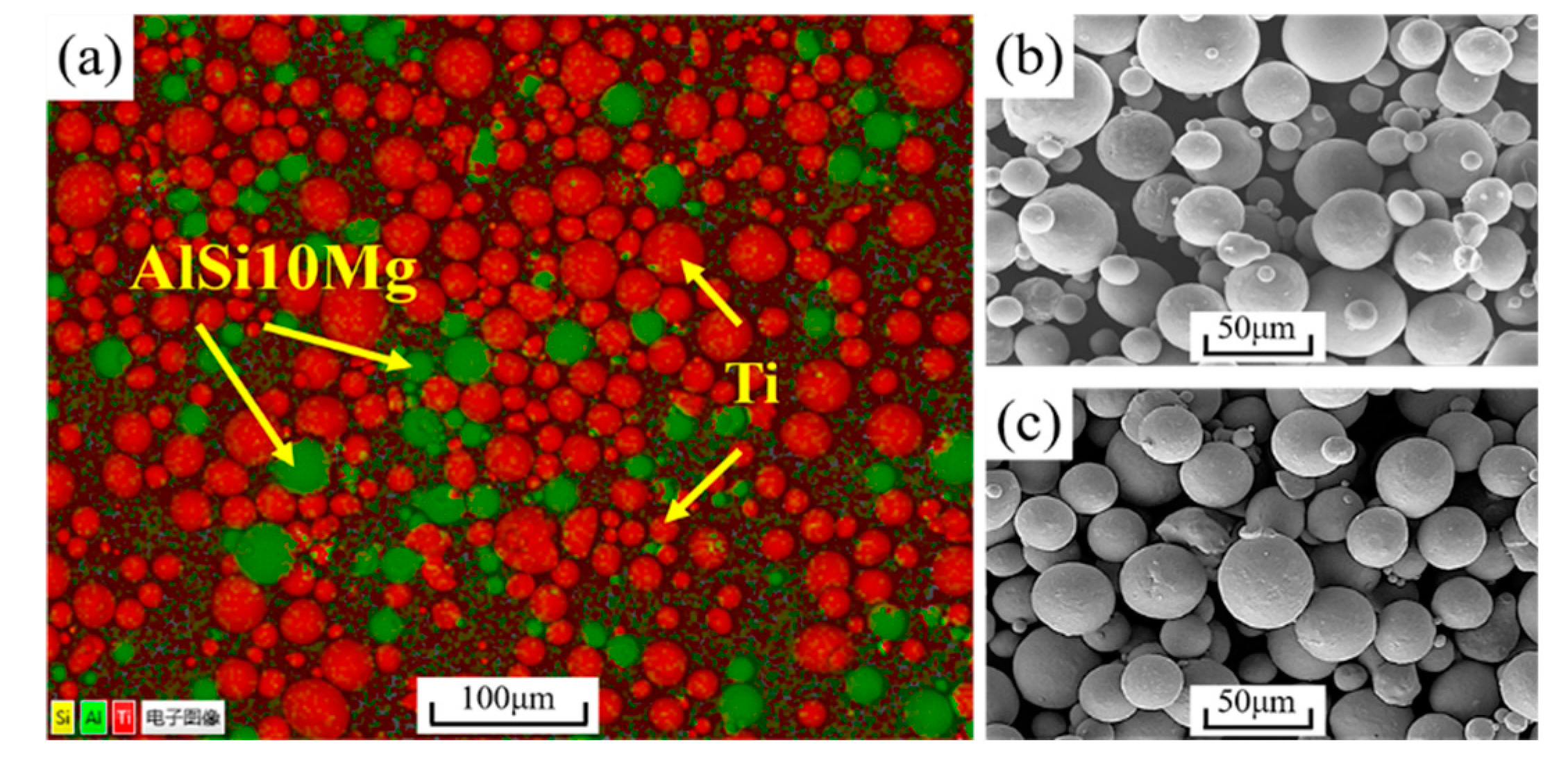
2.1. Materials

This work used Cp–Ti powder (AVIC Matt Powder Technology (Beijing) Co., Ltd., Beijing, China) and AlSi10Mg powder (AVIC Matt Powder Technology (Beijing) Co., Ltd., Beijing, China) mixed according to the weight ratio of 90:10. According to the particle size and chemical composition information given by the manufacturer, the particle sizes of the Cp-Ti powder and AlSi10Mg powder were 15–53 μm, with the average particle size of 30 μm. Table 1; Table 2 show the chemical composition of the Cp-Ti and AlSi10Mg powder. Figure 1 shows the EDS mapping photo of the mixed powder (Figure 1a), and powder morphology of Cp-Ti powder (Figure 1b), AlSi10Mg powder (Figure 1c), Cp-Ti powder and the AlSi10Mg powder, which were uniformly mixed.
A vertical planetary ball mill (Hunan Mi Qi Ball Mill, Inc., Nanjing, China) was used to mix the mixed powder (S1) and Cp-Ti powder (S2) to ensure that the powder was evenly mixed. To prevent the powder from being oxidized during the ball grinding, the ball-grinding tank was filled with argon. The parameters of ball grinding were as follows: The quality ratio of ball material was 1:1.5, with the ball-grinding speed of 200 RPM, the grinding balls were zirconia balls (8 mm), and the ball-grinding time was 240 min. During the process of ball grinding, in order to make the powder mix evenly and avoid the high temperature in the tank, the ball-grinding method was used—forward rotation for 10 min, reverse rotation for 10 min, and cooling for 10 min.

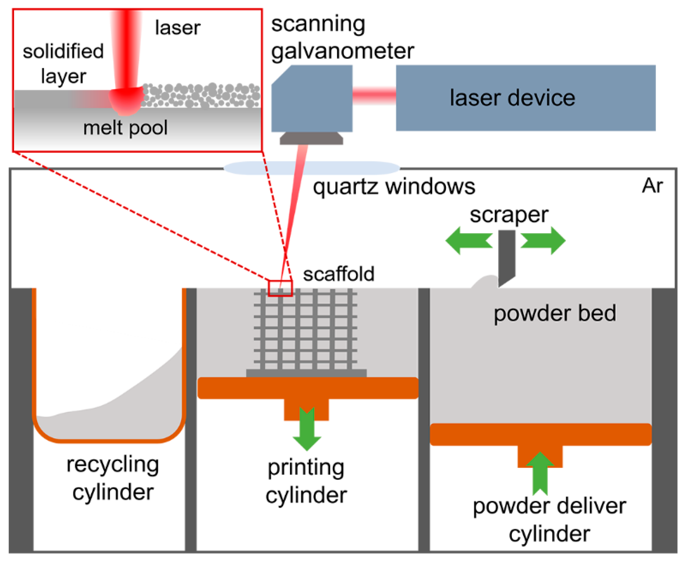
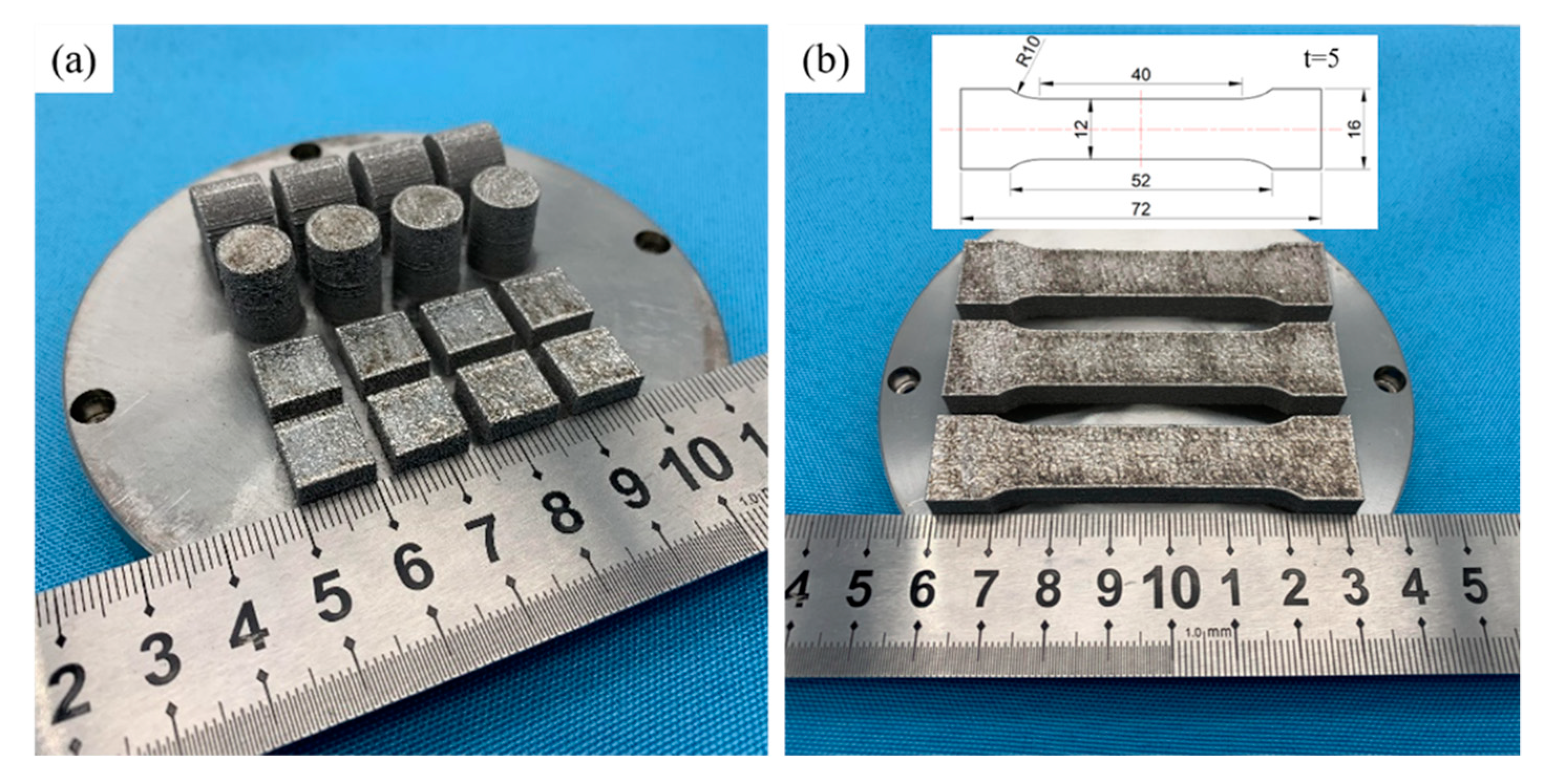
2.2. Experimental Equipment and Methods

The self-developed SLM equipment (RAP IV SLM; University of Aeronautics and Astronautics, Nanjing, China) was used (See Figure 2). During the printing process, argon gas was filled into the forming chamber for gas protection, and the oxygen content was limited to below 200 ppm. The workpiece was printed with the optimized process parameters (laser power of 300 W, scanning speed of 720 mm/s, hatch space of 100 μm, layer thickness of 50 μm, and substrate temperature of 200 °C). The SLM-processed samples are shown in Figure 3. There were four types of samples printed here, which were eight rectangular samples (10 mm × 10 mm × 5 mm), four vertical cylinders (10 mm × 12 mm), four horizontal cylinders (10 mm × 12 mm × 12 mm), and three tension samples (Figure 3b). After printing, the substrate was placed in the forming chamber and cooled to room temperature.

2.3. Test Instruments

The printed workpieces, cut from the substrate by wire cutting (HF250; Huafang Instruments, Inc., Hangzhou, China), were sliced longitudinally into pieces. The specimens were polished and etched with etchant solution containing 2% of Hydrofluoric acid and 4% of nitric acid (volume fraction). The microstructure was observed by a field emission scanning electron microscope (SEM) (S-4800; Hitachi Instruments, Inc., Tokyo, Japan), and elemental mapping scans were determined with energy dispersive X-ray spectroscopy (EDS) (INCA 200; Oxford Instruments, High Wycombe, UK) coupled to the SEM. In addition, a transmission electron microscope (TEM) (G2 T20, FEI Technologies Inc., Hillsboro, USA) was used to observe the microstructure.
After the workpieces were polished, the phase composition and grain size of the workpieces were analyzed using an X-ray diffraction (XRD) spectrometer (DMAX-2500PC; Rigaku Corp., Tokyo, Japan), with Cu Kα radiation at 40 kV and 150 mA, the parameters of the XRD test are as follows: angle range: 2θ = 30–80°, wavelength = 0.15406 nm, scanning speed: 10°/min; and then a digital intelligent microhardness tester (HV-1000; Haowei Optoelectronic Technology Co., Shanghai, China) was used to measure the microhardness of the workpieces. The load was 200 g and the loading time was 20 s.
At the same time, a high-speed reciprocating friction and wear tester (HSR–2M; Zhongke Kaihua Instruments Co., Lanzhou, China) was used for the friction and wear test. The load was 3 N, with a rotational speed of 300 RPM and a friction time of 10 min. The counterpart was a GCr15 steel ball with a diameter of 4 mm.
After the wear test, S-4800 SEM was used to observe the worn surface of the workpiece. A microcomputer controlled electro-hydraulic servo universal testing machine (SHT4605; Metis industrial systems co., Ltd., Shanghai, China) was used for the room-temperature compression and tensile experiment. The test machine was set to the speed control mode during the experiment, the compression rate was set at 0.5 mm/min, and the tensile rate was set at 1 mm/min.

3. Results and Discussion

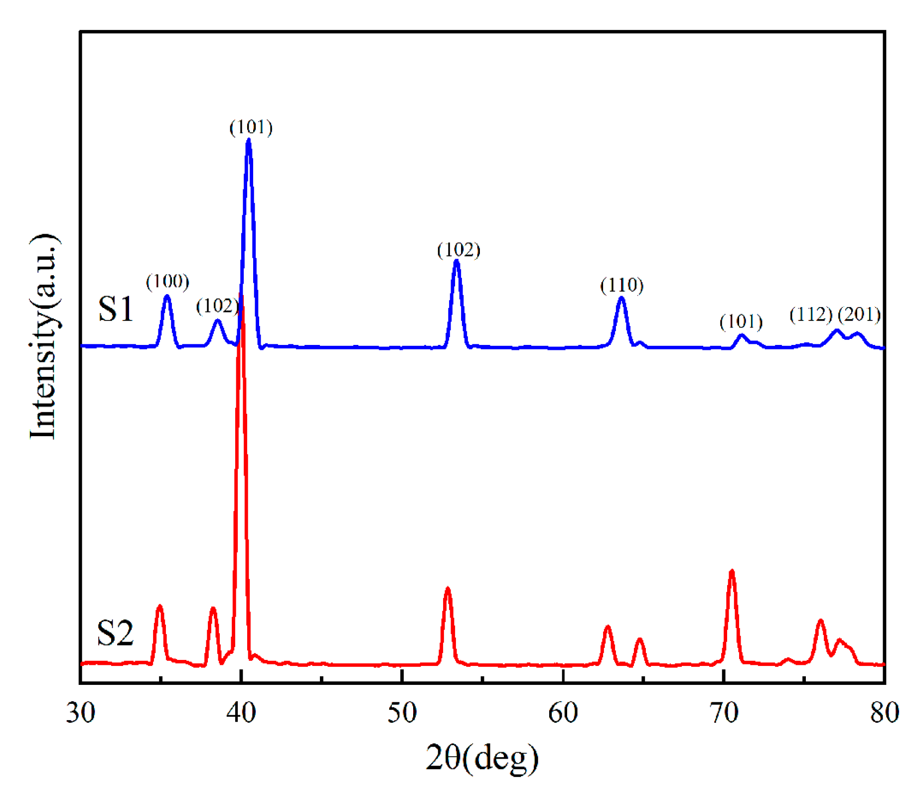
3.1. Phase Identification

Figure 4 shows the XRD patterns of the formed workpieces. Compared with the diffraction peak of S2, the diffraction peak of S1 slightly moves to the left. According to Bragg equation,
2 d s i n θ = n λ ( n = 1 , 2 ) ,
where d is the spacing between crystal surfaces; θ the angle of incidence X-ray with the corresponding crystal surface; λ the wavelength of X-ray; n the diffraction series. The 2θ position of the forming workpiece with the aluminum alloy was significantly shifted to a large angle. When θ, λ, and n are constant, the spacing between the crystal surfaces d decreases, which means that the interplanar spacing of the crystal was reduced. The Ti3Al is a hexagonal crystal, but some of the Ti atoms are replaced by Al atoms. Due to the change in its lattice structure, the interplanar spacing of the crystal was reduced. This result is consistent with the experimental results of XRD, which proves that the Al atom had been solid-dissolved into the Ti crystal to form the Ti3Al phase.

3.2. Mechanical Characterization
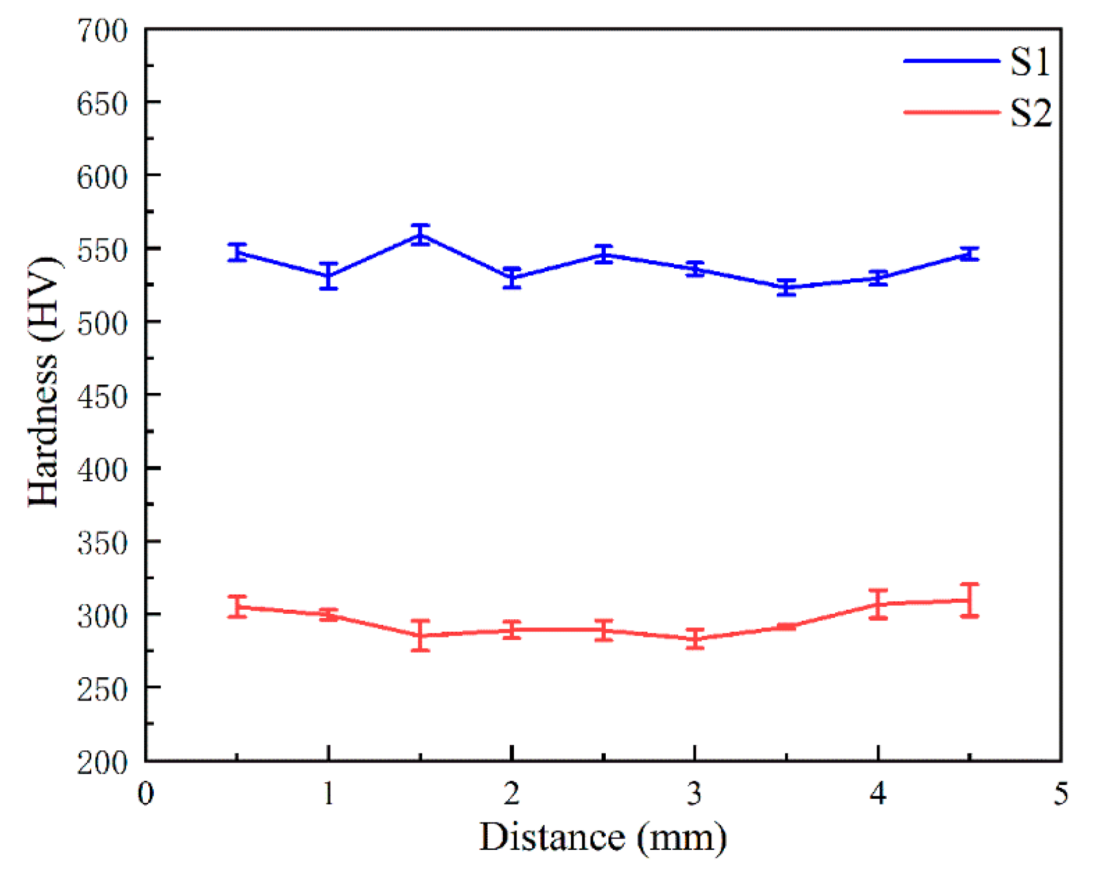
Figure 5a is the surface macroscopic morphology of the formed workpiece. It can be observed that molten pools formed at the cross section of the workpiece during the forming process. The molten pool has a clear boundary, and there are obvious vortex patterns in the molten pool. This pattern was caused by the melting of the two metals during the SLM process. In previous studies, this phenomenon is also observed in the welding pool of Zr-based magnesium alloy and Ti64 alloy [17]. Figure 5b–d show the EDS mapping. The distribution of Ti and Al in the workpiece is relatively uniform in this area, which indicates that Ti–Ti3Al metal composite can be produced by this method.
The cross-section is observed at high-powered mode under SEM (See Figure 6). A large number of off-white particles were precipitated on the surface of the workpiece, with a uniform grid structure. According to previous reports, when the content of the aluminum element is more than 5% [18], the supersaturated aluminum element in the alloy precipitates as white Ti3Al particles [19], which is consistent with the observed results.
By further magnifying this region, the average size of the precipitates was less than 200 nm (see Figure 6b). Figure 6c shows the TEM of this region. The elliptic Ti3Al particle with a size of about 200 nm was generated between two titanium crystals, which is consistent with the results observed by SEM. Figure 6d is the selected area diffraction pattern (SADP) corresponding to Figure 6c. The length and angle ratio of its SADP are completely in line with the standard diffraction pattern (PDF# 65-7534). Combined with the above analysis, the particles of the Ti3Al intermetallic compound spontaneously formed during the SLM forming process of the workpiece.

3.3. Hardness

Figure 7 shows the hardness distribution curve of SLM workpieces along the section of the forming direction. The hardness distribution of the SLM workpieces had no obvious change in the forming, with the average hardness of 538.56 HV. Compared with S2 formed by SLM, the hardness of S1 increased by 82.27% (295.46 HV). This can be attributed to the dispersion strengthening.
During the forming process, the Ti3Al particles formed by in-situ synthesis were uniformly dispersed between the grain boundaries, and a large number of dislocations were formed in the titanium matrix, resulting in dispersion strengthening. In addition, there were a lot of saturated α phases in the workpiece. The Al atoms dissolved in the α-Ti phases formed the solid solution strengthening which also increased the hardness of the workpiece.

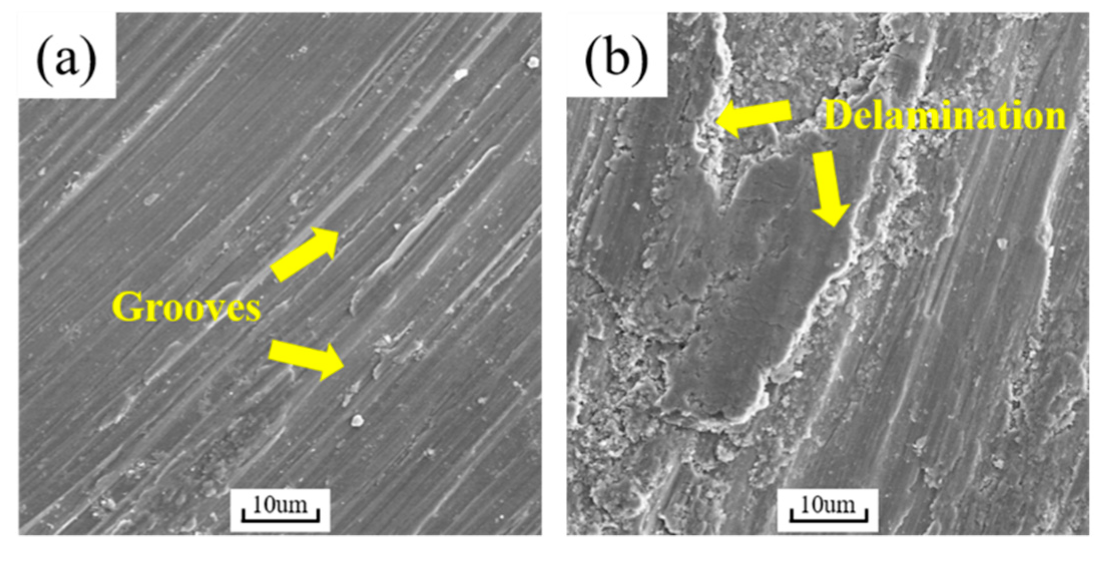
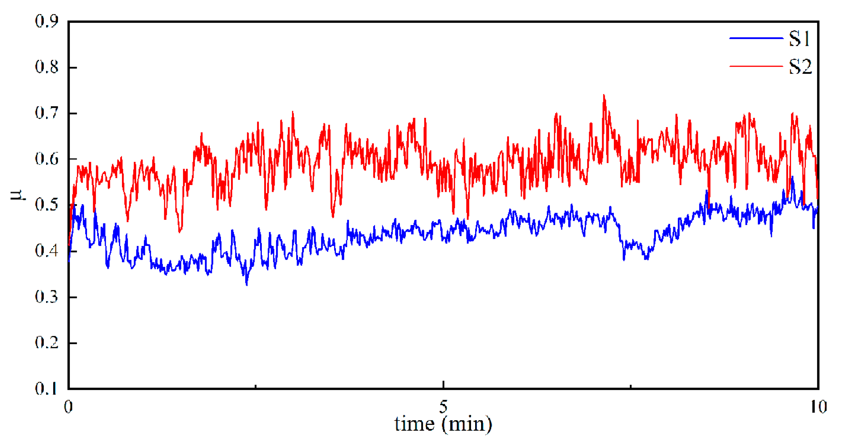
3.4. Wear Performance

Figure 8 shows the friction and wear curves of S1 and S2. Compared with S2, the friction coefficient of S1 is smaller. The average friction coefficient of S1 is 0.46, with smoother curve fluctuation, indicating that the overall friction process was relatively stable. However, the friction coefficient curve of S2 has a large fluctuation range, and the average friction coefficient is 0.59.
Figure 9 shows the topography of the samples’ surface after the wear test. Corresponding to the friction curve, the worn surfaces of the two workpieces show two different morphologies. Due to the movement of steel balls, deep furrow marks were left, which formed typical abrasive wear and adhesive wear. Owing to the poor wear resistance and poor hardness of Cp-Ti, plastic deformation appeared with deep furrows during the friction process. As the friction progressed, the continuous plastic deformation of the surface resulted in cracks, pores, and other defects under the friction surface, which finally caused spalling on the friction surface.
However, the surface of S1 was smooth and flat, and the wear mark was thinner than that of S2. Only a few fine abrasive particles adhered to it. From the micro perspective, the dispersion of nano Ti3Al particles in the workpiece played the role of dispersion strengthening, improving the hardness and strength of S1. Meanwhile, these Ti3Al particles prevented the generation of cracks, pores, and other defects, which delayed its further wear. Macroscopically, the improvement of hardness and the existence of nano Ti3Al particles made the surface of the workpiece form a strain-hardening layer during friction. It acted as a protective layer in the subsequent friction process, and ultimately improved the wear resistance of the workpiece [20].
According to the wear rate formula,
K = V / P   L ,  
where K (mm3/N × mm) is the wear rate; V (mm3) the volume wear; P (N) the normal load; L (mm) the relative sliding distance between friction pairs. The volume wear of the material can be expressed as follows:
V = [ π r 2 180 arcsin ( b 2 r ) b 2 r 2 b 2 4 ] π d
where r (mm) is the track radius of the wear mark; b (mm) the width of the wear mark.
According to the data obtained from the formula, the wear-mark widths of the two workpieces were 678.25 and 699.25 μm, and the wear rates of the two workpieces were 4.373 × 10⁵ and 4.792 × 10⁵, respectively. The wear rate of S1 was 8.74% lower than that of S2, which is consistent with the SEM results.

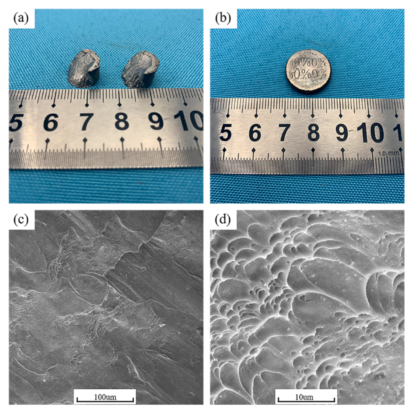
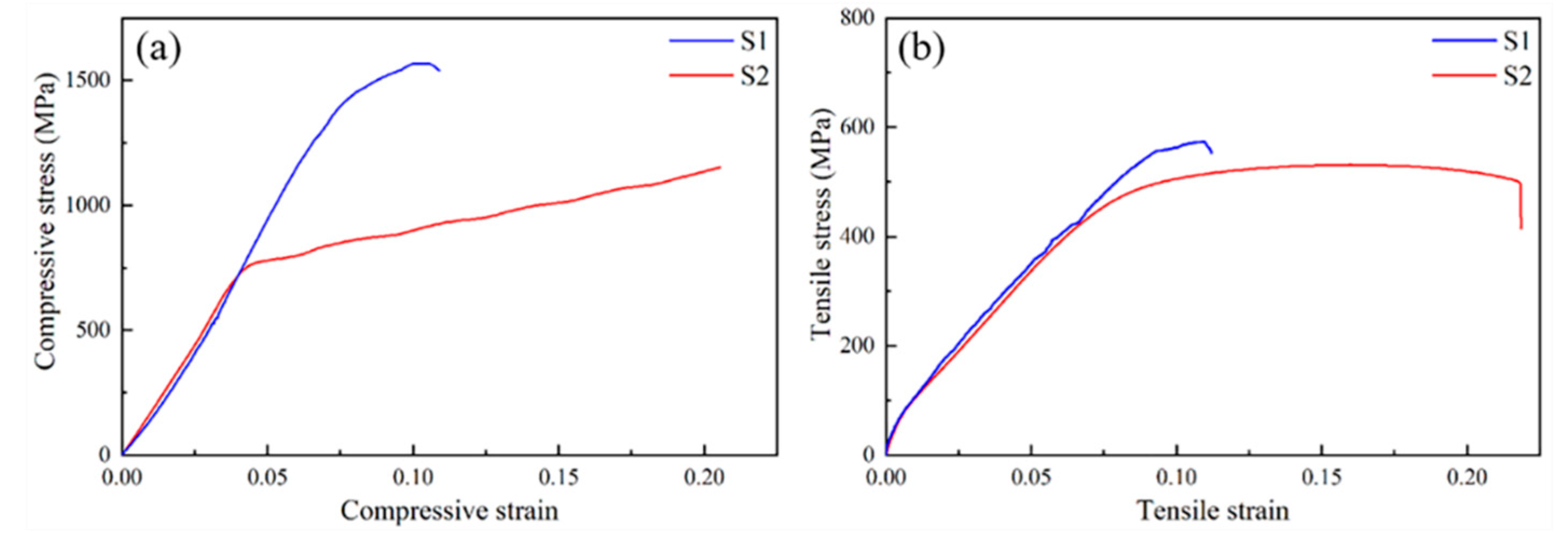
3.5. Tensile and Compression Test

The compression test, which is different from the tensile test, cannot be easily affected by micro machining defects in the forming process. Therefore, the compression test results can be used to test the intrinsic properties of the material (strength/work hardening) and to predict the tensile properties of the material [21].
Figure 10a shows the compression curve of the formed workpiece. Compared with S2, the plasticity of S1 decreased significantly. When the strain reached 0.11, a brittle fracture occurred. However, the strength had been greatly improved, with compressive yield strength (CYS) and ultimate compressive strength (UCS) reaching 1410 MPa and 1568 MPa, respectively. The tensile properties of S1 and S2 were studied at room temperature, and the obtained typical stress–strain curves are depicted in Figure 10b. It can be seen that S1 exhibited obvious brittle characteristics and could not resist large plastic deformation. Its YS (yield strength) and UTS (ultimate tensile strength) were 554 MPa and 567 MPa, respectively. S2 exhibited good toughness under tensile stress and had an obvious plastic deformation zone. Its YS and UTS were 432 MPa and 531 MPa.
The main reason for the improvement in compression performance is that aluminum atoms form solid solution strengthening in titanium crystal, which greatly improved the hardness and compressive strength of the workpiece. At the same time, the precipitated Ti3Al particles formed a large number of dislocations in the metal matrix. Due to the Orovan mechanism [22], these enhanced phases can hinder the movement of dislocations. When plastic deformation occurs, the sample needs to overcome greater resistance.
Figure 11 shows the compression test workpieces of S1 and S2 and the microstructure of S1. S2 showed plastic deformation during compression, while S1 obtained a brittle fracture. The fracture of the workpiece presented a mixture of smooth shear belt and rough belt at low magnification. In the work, titanium contributed to the plasticity of the workpiece as the ductile phase, while Ti3Al played a role in strengthening as the reinforcing phase [23]. The increase in flow stress during the deformation process of composites is mainly due to the load transfer from the matrix to the reinforcing particles, as well as the effect of the particles on the dislocations. Ti3Al particles can be expressed as the reinforcing phase in the composite [24].

4. Conclusions

The Ti-Ti3Al composite was prepared with Cp-Ti powder and AlSi10Mg powder using SLM and in-situ synthesis technology. The microstructure and mechanical properties of the Ti-Ti3Al composite were studied. The following conclusions can be obtained.
(1)
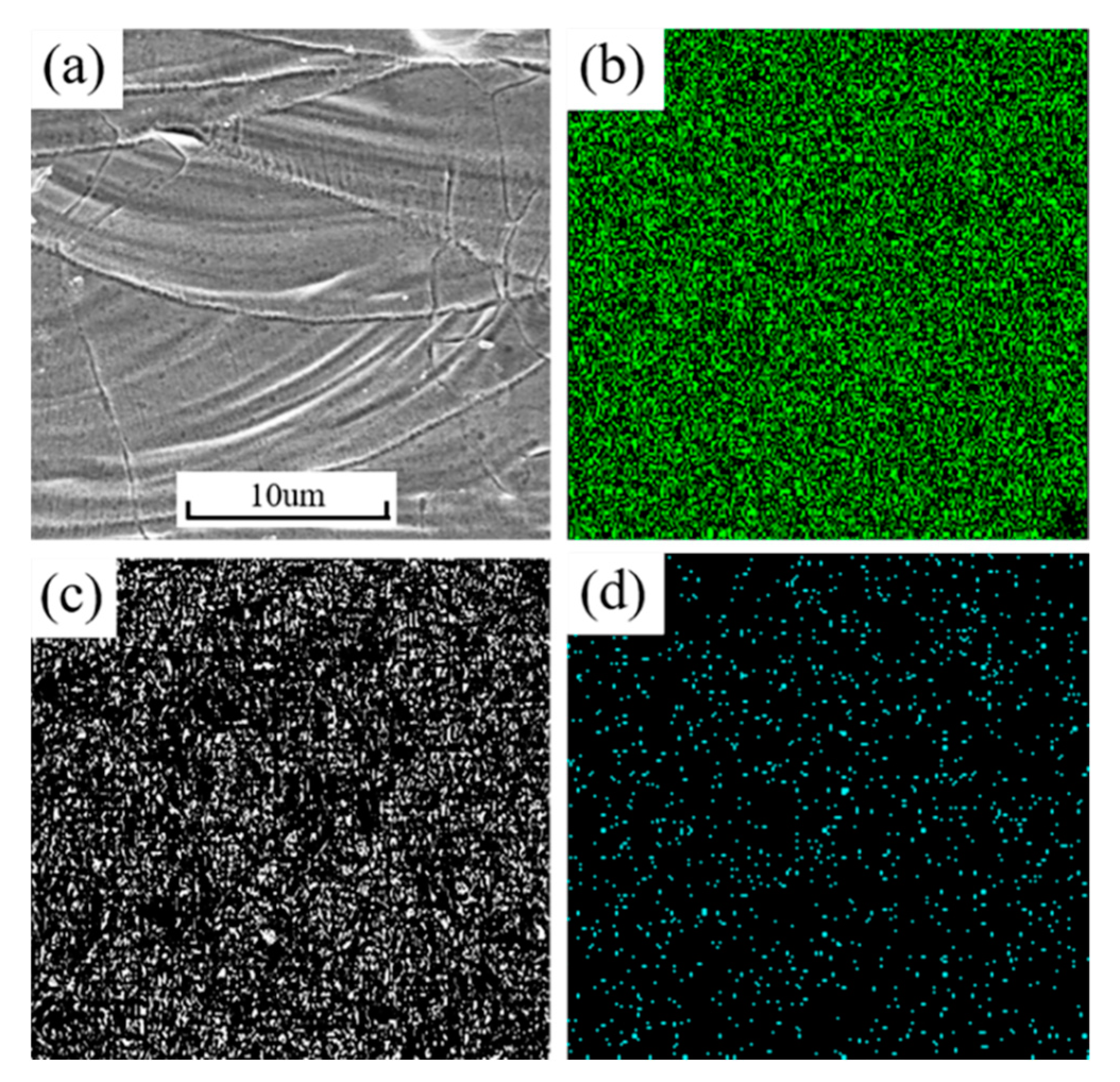
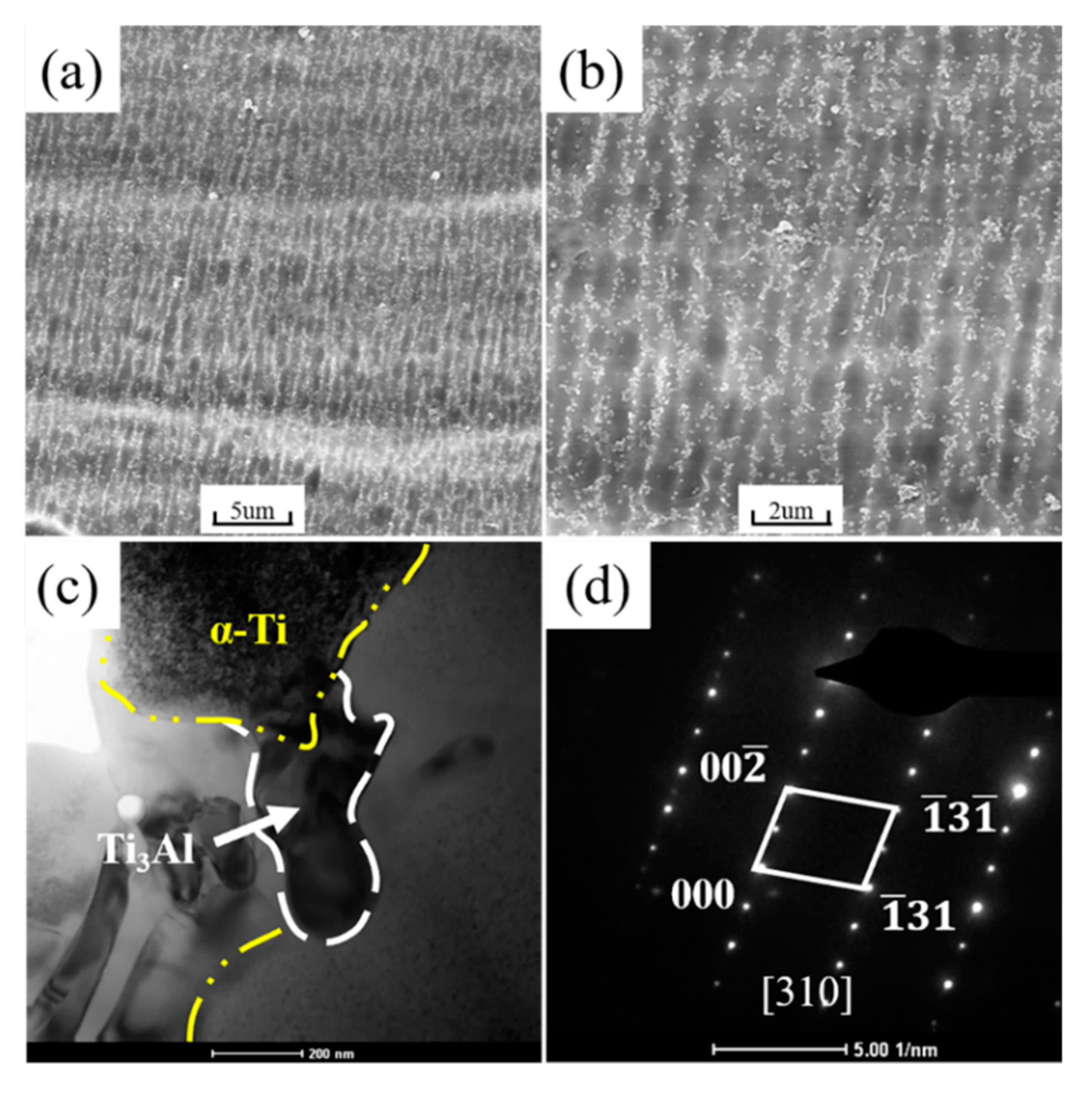
Nano Ti3Al particles were precipitated out of the formed workpiece, with the technological parameters used in the work. The α phase in the titanium matrix was transformed into a supersaturated α phase.
(2)
Due to the dispersion strengthening of Ti3Al particles and the solid solution strengthening of the Al element in Ti crystal, the microhardness of Ti-based composites treated by SLM was significantly improved. With parameters of 300 W and 720 mm/s, the microhardness of the workpiece with Al was 538.56 HV, almost twice that of the Cp-Ti workpiece (218.10 HV).
(3)
Compared with the Cp–Ti sample, the wear resistance, tensile resistance and compression resistance of the sample were improved after adding aluminum. The wear and deformation of the sample were prevented by the interaction of the precipitated Ti3Al particles and the supersaturated α-Ti.

Author Contributions

Conceptualization, Y.L. and H.L.; methodology, Z.T. and Y.Y.; investigation, L.Z. and C.W.; writing—review and editing, Y.L. and H.L.; visualization; project administration, L.S.

Funding

The work was financially supported by the Advanced Research Project of Army Equipment Development (301020803), the Young Scientists Fund of the National Natural Science Foundation of China (51605473), the Jiangsu Provincial Research Foundation for Basic Research, China (BK 20161476), the Science and Technology Support Program of Jiangsu (BE 2016010-3).

Conflicts of Interest

The authors declare no conflict of interest.

References

  1. Banerjee, D.; Williams, J.C. Perspectives on Titanium Science and Technology. Acta Mater. 2013, 61, 844–879. [Google Scholar] [CrossRef]
  2. Wennerberg, A.; Albrektsson, T. Effects of titanium surface topography on bone integration: A systematic review. Clin. Oral Implant. Res. 2009, 20, 172–184. [Google Scholar] [CrossRef] [PubMed]
  3. Chan, K.S.; Leverant, G.R.; Perocchi, L. Constitutive properties of hard-alpha titanium. Metall. Mater. Trans. A 2000, 31, 3029–3040. [Google Scholar] [CrossRef]
  4. Lütjering, G.; Williams, J.C. Titanium; Springer Science & Business Media: Berlin, Germany, 2007. [Google Scholar]
  5. Lee, D.G.; Lee, S. Effects of nano-sized α2 (Ti3Al) particles on quasi-static and dynamic deformation behavior of Ti-6Al-4V alloy with bimodal microstructure. J. Mater. Sci. 2005, 40, 4077–4084. [Google Scholar] [CrossRef]
  6. Gibson, I.; Rosen, D.; Stucker, B. Additive Manufacturing Technologies; Springer: New York, NY, USA, 2010. [Google Scholar]
  7. Aboulkhair, N.T.; Maskery, I.; Tuck, C.; Ashcroft, I.; Everitt, N.M. The microstructure and mechanical properties of selectively laser melted AlSi10Mg: The effect of a conventional T6-like heat treatment. Mater. Sci. Eng. A 2016, 667, 139–146. [Google Scholar] [CrossRef]
  8. Suryawanshi, J.; Prashanth, K.G.; Scudino, S.; Eckert, J.; Prakash, O.; Ramamurty, U. Simultaneous enhancements of strength and toughness in an Al-12Si alloy synthesized using selective laser melting. Acta Mater. 2016, 115, 285–294. [Google Scholar] [CrossRef]
  9. Shuai, C.; Cheng, Y.; Yang, Y.; Peng, S.; Yang, W.; Qi, F. Laser additive manufacturing of Zn-2Al part for bone repair: Formability, microstructure and properties. J. Alloys Compd. 2019, 798, 606–615. [Google Scholar] [CrossRef]
  10. Gu, D.; Shen, Y.; Lu, Z. Preparation of TiN-Ti5Si3 in-situ composites by selective laser melting. Mater. Lett. 2009, 63, 1577–1579. [Google Scholar] [CrossRef]
  11. Sahoo, P.; Koczak, M.J. Microstructure-property relationships of in situ reacted TiC/Al Cu metal matrix composites. Mater. Sci. Eng. A 1991, 131, 69–76. [Google Scholar] [CrossRef]
  12. Chrysanthou, A.; Erbaccio, G. Production of copper-matrix composites by in situ processing. J. Mater. Sci. 1995, 30, 6339–6344. [Google Scholar] [CrossRef]
  13. Wang, L.; Arsenault, R.J. Interfaces in XD processed TiB 2 /NiAl composites. Metall. Trans. A 1991, 22, 3013–3018. [Google Scholar] [CrossRef]
  14. Yang, Y.; Yuan, F.; Gao, C.; Feng, P.; Xue, L.; He, S.; Shuai, C. A combined strategy to enhance the properties of Zn by laser rapid solidification and laser alloying. J. Mech. Behav. Biomed. Mater. 2018, 82, 51–60. [Google Scholar] [CrossRef] [PubMed]
  15. Jangg, G.; Kutner, F.; Korb, G. Dispersion hardening of aluminium with Al 4C 3. Powder Metall. 1977, 9, 24–26. [Google Scholar]
  16. Ma, Z.Y.; Li, J.H.; Li, S.X.; Ning, X.G.; Lu, Y.X.; Bi, J. Property-microstructure correlation in in situ formed Al2O3, TiB2 and Al3Ti mixture-reinforced aluminium composites. J. Mater. Sci. 1996, 31, 741–747. [Google Scholar] [CrossRef]
  17. Li, Y.; Shen, Y.; Leu, M.C.; Tsai, H.-L. Building Zr-based metallic glass part on Ti-6Al-4V substrate by laser-foil-printing additive manufacturing. Acta Mater. 2018, 144, 810–821. [Google Scholar] [CrossRef]
  18. Lu, L.; Lai, M.O.; Wang, H.Y. Synthesis of titanium diboride TiB2 and Ti-Al-B metal matrix composites. J. Mater. Sci. 2000, 35, 241–248. [Google Scholar] [CrossRef]
  19. Wu, H.; Fan, G.; Geng, L.; Cui, X.; Huang, M. Nanoscale origins of the oriented precipitation of Ti 3 Al in Ti Al systems. Scr. Mater. 2016, 125, 34–38. [Google Scholar] [CrossRef]
  20. Gu, D.; Meng, G.; Li, C.; Meiners, W.; Poprawe, R. Selective laser melting of TiC/Ti bulk nanocomposites: Influence of nanoscale reinforcement. Scr. Mater. 2012, 67, 185–188. [Google Scholar] [CrossRef]
  21. Zhang, L.C.; Das, J.; Lu, H.B.; Duhamel, C.; Calin, M.; Eckert, J. High strength Ti-Fe-Sn ultrafine composites with large plasticity. Scr. Mater. 2007, 57, 101–104. [Google Scholar] [CrossRef]
  22. Kang, Y.C.; Chan, S.L.I. Tensile properties of nanometric Al2O3 particulate-reinforced aluminum matrix composites. Mater. Chem. Phys. 2004, 85, 438–443. [Google Scholar] [CrossRef]
  23. He, G.; Löser, W.; Eckert, J. In situ formed Ti-Cu-Ni-Sn-Ta nanostructure-dendrite composite with large plasticity. Acta Mater. 2003, 51, 5223–5234. [Google Scholar] [CrossRef]
  24. Trojanová, Z.; Gärtnerová, V.; Jäger, A.; Námešný, A.; Chalupová, M.; Palček, P.; Lukáč, P. Mechanical and fracture properties of an AZ91 Magnesium alloy reinforced by Si and SiC particles. Compos. Sci. Technol. 2009, 69, 2256–2264. [Google Scholar] [CrossRef]
Figure 1. (a) EDS mapping photo of mixed powder, powder morphology of (b) Cp-Ti and (c) AlSi10Mg.
Metals 09 01121 g001
Figure 2. System diagram of NUAA RAP IV.
Metals 09 01121 g002
Figure 3. (a) Samples of compression, hardness and wear resistance tests (b) sample of tensile test.
Metals 09 01121 g003
Figure 4. XRD patterns of selective laser melting (SLM) formed workpieces.
Metals 09 01121 g004
Figure 5. (a) Macroscopic morphology of workpiece surface, and EDS Mapping photos of corresponding areas (b) titanium, (c) aluminum, (d) silicon.
Metals 09 01121 g005
Figure 6. (a,b) SEM images, (c) TEM images and (d) selected area diffraction pattern (SADP) of the workpieces.
Metals 09 01121 g006
Figure 7. Microhardness distribution of the formed workpiece along the forming direction.
Metals 09 01121 g007
Figure 8. Changes of the coefficient wear for S1 and S2 vs. the wear test time.
Metals 09 01121 g008
Figure 9. Topography of samples surface after the wear test: (a) S1, (b) S2.
Metals 09 01121 g009
Figure 10. Stress–strain curve of SLM-formed workpieces, (a) compression test (b) tensile test.
Metals 09 01121 g010
Figure 11. The compression test workpieces of S1 (a) and S2 (b) and (c,d) the fractures of S1.
Metals 09 01121 g011
Table 1. Chemical composition of Cp-Ti powder (wt%).
TiCFeNOH
Balance0.0120.0230.0100.0580.001
Table 2. Chemical composition of AlSi10Mg powder (wt%).
AlCuMgFeSiMnZn
Balance0.050.6230.0109.6240.010.03

