Article

Ultrasonic-Assisted Laser Metal Deposition of the Al 4047Alloy

1
School of Materials Science and Engineering, Shijiazhuang Tiedao University, Shijiazhuang 050043, China
2
State Key Laboratory of Mechanical Behavior and System Safety of Traffic Engineering Structures, Shijiazhuang Tiedao University, Shijiazhuang 050043, China
*
Authors to whom correspondence should be addressed.
Metals 2019, 9(10), 1111; https://doi.org/10.3390/met9101111
Submission received: 26 September 2019 / Revised: 12 October 2019 / Accepted: 14 October 2019 / Published: 17 October 2019

Abstract

:
Ultrasonic-assisted laser metal deposition (UALMD) technology was used to fabricate Al 4047 parts. The effect of the powder feeding laser power, remelting laser power and ultrasonic power on the relative density of the parts was investigated. The relative density, microstructure and mechanical properties of the specimens obtained by the optimized process parameters were compared with the corresponding properties of the cast alloys. The results showed that dense alloys with a maximum density of 99.1% were prepared using ultrasonic vibration and by remelting the previously deposited layer with the optimized processing parameters, and its density was almost equivalent to that of the cast parts. The microstructure of the samples using optimal laser parameters presented columnar Al dendrites and equiaxed Si particles at the boundary of each deposited layer, while the supersaturated Al solid solution was transformed into equiaxed crystal surrounded by fine fibrous Si phases at the center of the layer. Moreover, the size of the primary Al and the Si particles in the samples produced by UALMD was remarkably refined compared to that of the primary Al and Si particles in the cast structure, resulting in grain refining strengthening. The observed variation in the microstructure had an obvious impact on the tensile properties. The mechanical behavior of the deposit obtained by UALMD revealed superior tensile strength, yield strength and tensile ductility values of 227 ± 3 MPa, 107 ± 4 MPa and 12.2 ± 1.4%, which were approximately 51%, 38% and 56% higher than those of the cast materials, respectively.

1. Introduction

Laser metal deposition (LMD), as a powder feeding laser additive manufacturing technology, has the ability to directly melt raw powder to make dense components via computer-aided design data [1,2]. Compared to conventional manufacturing techniques, such as casting, forging and machining processes, the LMD method is especially suitable for small batch production or repair of geometrically complex structures without the need for expensive molds, and this technology offers a promising perspective in the aerospace and transportation industries [3,4,5].
LMD technology has been successfully applied to manufacture a wide variety of metal materials, such as titanium alloys, nickel alloys and stainless steels [6,7,8]. However, LMD technology has encountered great challenges in the preparation of aluminium alloy materials due to the high laser reflectivity, high heat conductivity and high affinity to oxygen of aluminium alloys [9,10]. Porosity is one of the major defects in aluminium alloy components processed by laser additive manufacturing. Certain studies have shown that the formation of residual pores is related to stress concentration, which guarantees worse mechanical performance of the deposited metal [11,12]. Therefore, it is necessary to study the influence of the processing parameters on the defects of insufficient densification.
At present, studies on the densification behavior in the process of laser additive preparation of aluminium alloys have mostly concentrated on the selective laser melting (SLM) method, which is typically a laser powder bed fusion technique [13,14]. For instance, Wang et al. [15] prepared Al-12Si alloy by SLM under three different shielding gases, achieving aluminium alloy parts with a relative density of over 97%. The ductility of the parts protected by helium was slightly lower than those of the other two atmospheres due to the pore clusters. Read et al. [16] enhanced the relative density of an AlSi10Mg alloy built by SLM, indicating that the minimum pore fraction could be obtained when the optimized energy density was above 60 J/m3. Yu et al. [17] discussed the remelting process on the densification mechanism of an AlSi10Mg alloy manufactured by SLM. When the depth of the remelted layer was greater than half of the deposited layer, the residual pores were eliminated.
Compared with the SLM method, LMD technology has the advantages of high deposition efficiency and is suitable for the preparation of large-sized parts. Furthermore, it can not only build a single kind of metal material but can also be used for the production of functionally graded materials [18,19]. However, the molten pool of the LMD technology is deep, and the dendrite crystals are coarse due to the large heat input, leading to a lack of effective degassing measures [20,21]. Thus, limited work on the densification process of aluminium alloys fabricated by LMD technology has been published [22].
Ultrasonic degassing has been proven to be an effective way to increase the density of samples during the casting of aluminium alloys [23]. Puga et al. [24] studied the effect of processing parameters on the degassing efficiency of an AlSi9Cu3 alloy. The results confirmed that the degassing efficiency and the maximum alloy density depended on the electric power, processing time and melting temperature. Xu et al. [25] designed three different experimental systems for ultrasonic degassing. When ultrasonic vibration was used alone, only hydrogen in a small volume melt could be eliminated. However, when the ultrasonic vibration was combined with a purging gas, the gas in a 5 kg aluminium melt could be effectively removed within 5 min. In contrast to the molten pool of the casting process, the laser molten pool has the characteristics of fast heating and cooling. The mechanism of ultrasonic degassing in the nonequilibrium solidification of the laser molten pool is still unclear.
Ultrasonic-assisted laser metal deposition (UALMD) technology was used to prepare Al4047 alloys in this research. The aim of this paper is to investigate the relationship between porosity evolution in UALMD-fabricated samples and processing parameters such as the powder feeding laser power, remelting laser power and ultrasonic vibration power. Then, the microstructural observation and compositional analysis data of the cast parts and UALMD-optimized samples were compared. The influence of different preparation processes on the mechanical properties and fracture behavior was also discussed.

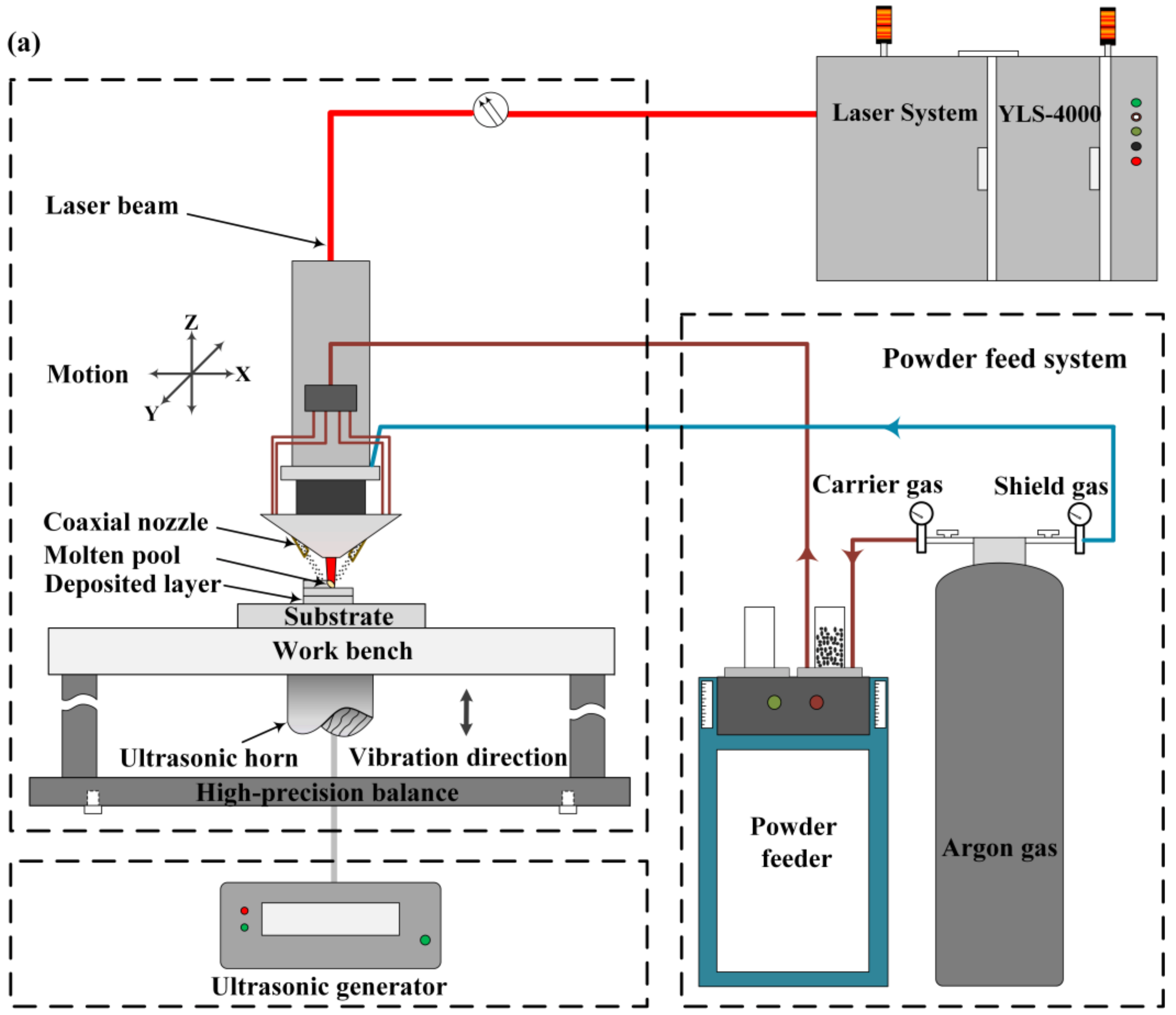
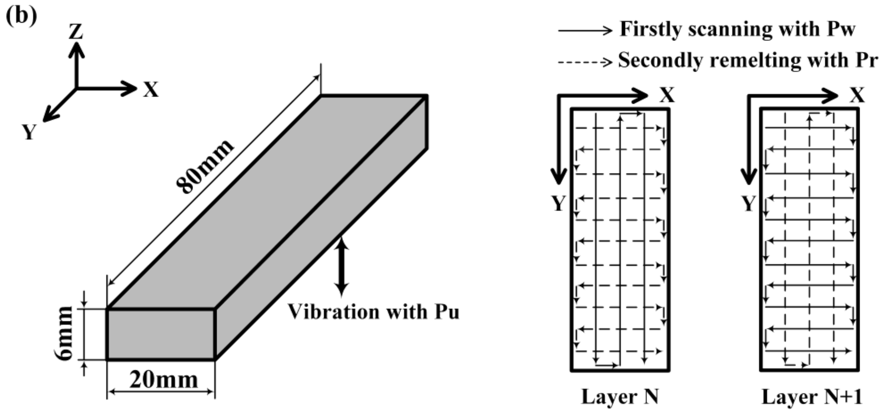
2. Materials and Methods

The experiments were performed with a gas-atomized 4047 aluminium powder (supplied by Titd Metal Materials Co., Ltd., China) that had a chemical composition of Si 11.96 wt%, Fe 0.22 wt% and Al for the balance. The 4047 aluminium powder had a near ellipsoid shape and a size range of 60–150 μm. The powder was placed in a vacuum chamber under a temperature of 393 K for 6 h before the deposition experiment to reduce the moisture adsorbed on the surface of the powder.
The UALMD experimental system, as schematically shown in Figure 1a, was composed of a YLS-4000 fiber laser with a maximum power of 4000 W and a spot size of 2 mm, a coaxial powder deposition device, a process control system, and an ultrasonic vibrator apparatus. A schematic diagram of the UALMD process is shown in Figure 1b. Under the conditions of the powder feeding laser power (Pw), the laser continuously melted the base metal or the previously deposited metal and the metal powder to form a thin deposited layer. Afterwards, the remelting laser power (Pr) was implemented vertically to the current layer without powder feeding. From beginning to end, ultrasonic vibration power (Pu) was applied through the bottom of the substrate and propagated into the laser metal pool with the action of the laser. The changes of the three powers parameters are shown in Table 1. After the preparation of a layer of sample, the above process was repeated after rotating by 90 degrees until the whole part was built.
To increase the density of the samples, based on a series of preliminary experiments, the fixed processing parameters were optimized as shown in Table 2. In the test, the frequency and maximum output amplitude of the s were 20 kHz and 25 µm, respectively. The pre-pressure between the ultrasonic horn and the workbench was 0.4 MPa. In addition, powders of the same composition were cast into ingots by vacuum melting to contrast the microstructure and tensile properties with those characteristics of the UALMD-produced samples.
The parts produced by UALMD processing were cut, ground and polished according to the standard techniques for metallographic sample preparation. The macroscopic morphology was observed using optical microscopy (OM) (ZEISS Imager. M2m) (Carl Zeiss Microimaging GmbH, Gottingen, Germany) after samples were etched with a solution composing H2O (95 mL), HNO3 (2.5 mL), HCl (1.5 mL), and HF (1 mL) for 20 s, and microstructures were examined by scanning electron microscopy (SEM) (ZEISS Gemini SEM 300) (Carl Zeiss Microscopy GmbH, Oberkochen, Germany) with a microscope equipped with a Bruker Quantax energy dispersive X-ray spectroscope (EDS) (Bruker Nano GmbH, Berlin, Germany). Phase identification of the samples was performed by an Empyrean X-ray diffractometer (XRD) (PANalytical, Almelo, Netherlands) with Co Kα radiation using a continuous scan mode at 35 kV and 50 mA. The scan rate of 1 deg/min was used over a range of 2θ = 30–100°.
The density of the specimens was determined by the Archimedes principle, using a theoretical density of 2.68 g/cm3. The tensile properties of the specimens were evaluated at room temperature on a TIANCHEN WOW-10G (China Jinan TIANCHEN Testing Machine Manufacturing CO. LTD, Jinan, China) testing machine with a Fiedler extensometer at a strain rate of 0.2 mm/min. For the data acquisition of the density and tensile properties, at least three samples were averaged under the same process. The surface characteristics of the tensile fracture were also analyzed by SEM.

3. Results and Discussion

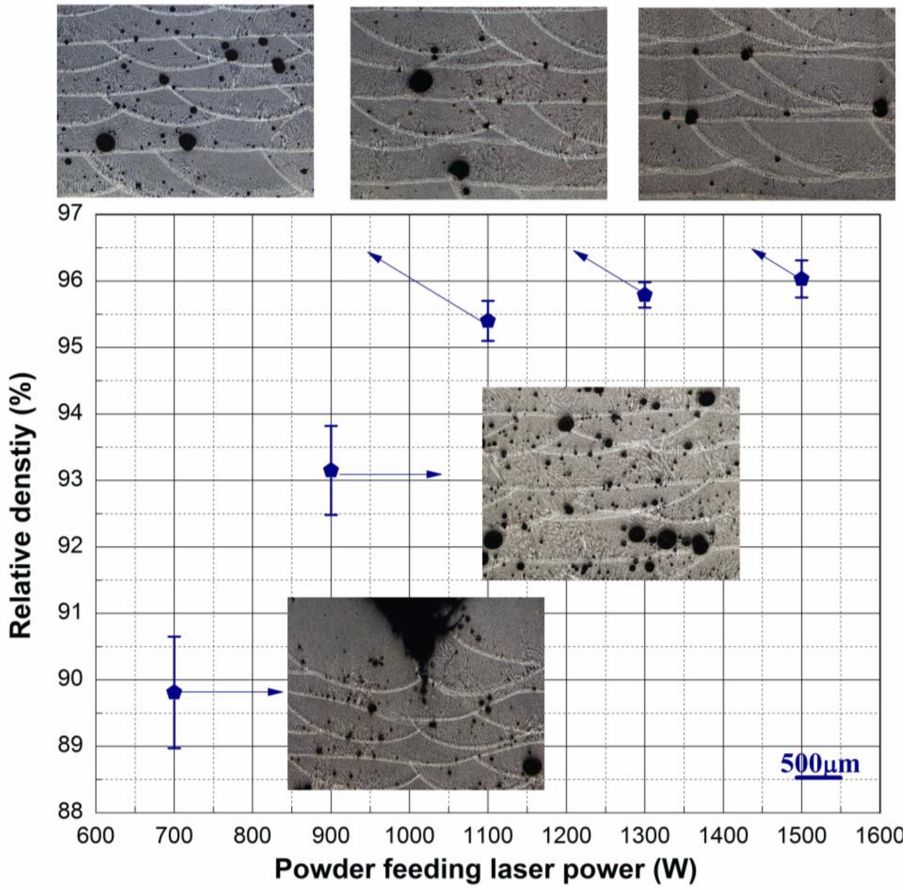
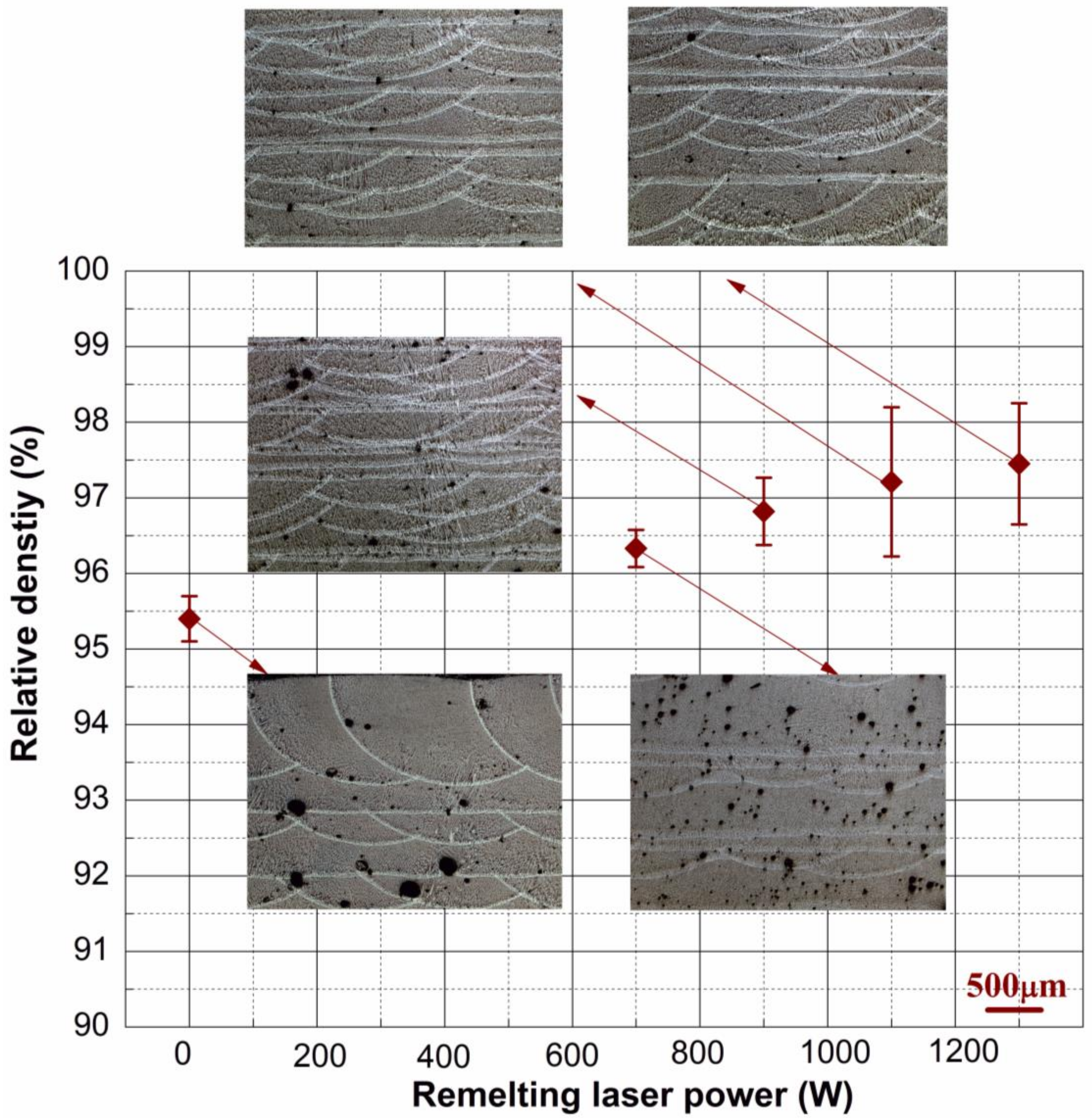
3.1. Densification Behavior

Figure 2 shows the effect of the powder feeding laser power on the relative density of the deposited samples. The relative density increased rapidly, first with the enhancement of the Pw and then displayed a slow growth at Pw values above 1100 W. When the Pw was low (700 W), there were some defects of incomplete fusion in the deposited layer, and it was difficult to obtain a good overall shape of the sample. Increased Pw could improve the overlap rate of the deposited layer, helping to form a continuous part. However, when the applied Pw was too high (1500 W), it caused severe splashing, which affected the surface appearance of the samples.
When the Pw exceeded 1100 W, although no obvious defects of incomplete fusion existed in the deposited layer, there were still circular pores with a volume fraction of less than 5% and a size range of 8–310 μm. Typical porosities common in the laser additive preparation of Al alloy were keyhole induced porosities, insufficient melting pores and gas induced porosities [18]. By properly controlling the laser energy density, the first two kinds of defects could be avoided. However, the gas induced porosities which were almost spherical in shape were difficult to eliminate. In this paper, the inert gas argon was used as a shielding gas in the laser melting deposition process, which was insoluble in the liquid molten pool. Since hydrogen was the only gas that might be dissolved in the Al alloy, the pores in the laser-deposited aluminium alloy were most likely to be hydrogen porosity [13]. At high temperatures, hydrogen had a high solubility in Al alloys. When cooled and solidified, the solubility dropped abruptly, and supersaturated hydrogen precipitated as hydrogen pores [26]. Because the laser solidification rate was too fast, it was difficult for the hydrogen pores to float up and escape from the surface of the molten pool. Therefore, residual pore defects were formed.
To further remove the residual pores in the samples, the same deposited layer was remelted. The relationship between the remelting laser power and the relative density values of the samples is shown in Figure 3. As the Pr increased from 0 W to 1300 W, the average relative density of the samples improved from 95.4% to 97.4%. In the powder-feeding laser deposition process, the powder had a large specific surface area, and the surface crystallization water was the main source of hydrogen in the laser molten pool [27]. The powder was not introduced during the remelting process, which reduced the source of hydrogen. In addition, the remelting process facilitated the escape of existing hydrogen pores, resulting in a reduction of the pore content in the samples.
When the remelting power was 0 W, there were many pores of different sizes in the deposited layer. When the remelting power reached 1100 W, the depth of the remelted layer was almost the same as the depth of the powder feeding layer, and the density was greatly improved. However, some residual pores with a size of less than 100 μm adhered to the boundary of the molten pool. Remelting treatment alone could not completely eliminate the hydrogen in the liquid metal, and a small amount of hydrogen would precipitate in the subsequent cooling solidification as the solubility changed. These small pores attached to the boundary of the molten pool were difficult to remove by continuously increasing the remelting power.
On the basis of laser remelting, the ultrasonic vibration synchronized with the laser application was implemented to further improve the density of the parts. As shown in Table 3, the density of the samples increased as the ultrasonic power increased. Samples with a maximum density of 99.1% were achieved with a maximum ultrasonic power of 1000 W, which was almost the same as the cast parts (99.1 ± 0.3%) with the same powder.
The action of ultrasonic waves on the liquid metal produced cavitation and acoustic streaming. The hydrogen atoms dissolved in the liquid metal diffused into the cavitation bubbles, and some of the cavitation bubbles gathered up and floated to escape from the surface of the molten pool. In addition, the acoustic flow also promoted the convection of the liquid pool and facilitated the escape of small pores attached to the boundary of the deposited layer [28,29]. Increasing the ultrasonic power improved the influence of the ultrasonic action and effectively removed excess hydrogen in the liquid molten pool. Since the hydrogen content was lowered, the pores formed during the solidification process were also reduced.

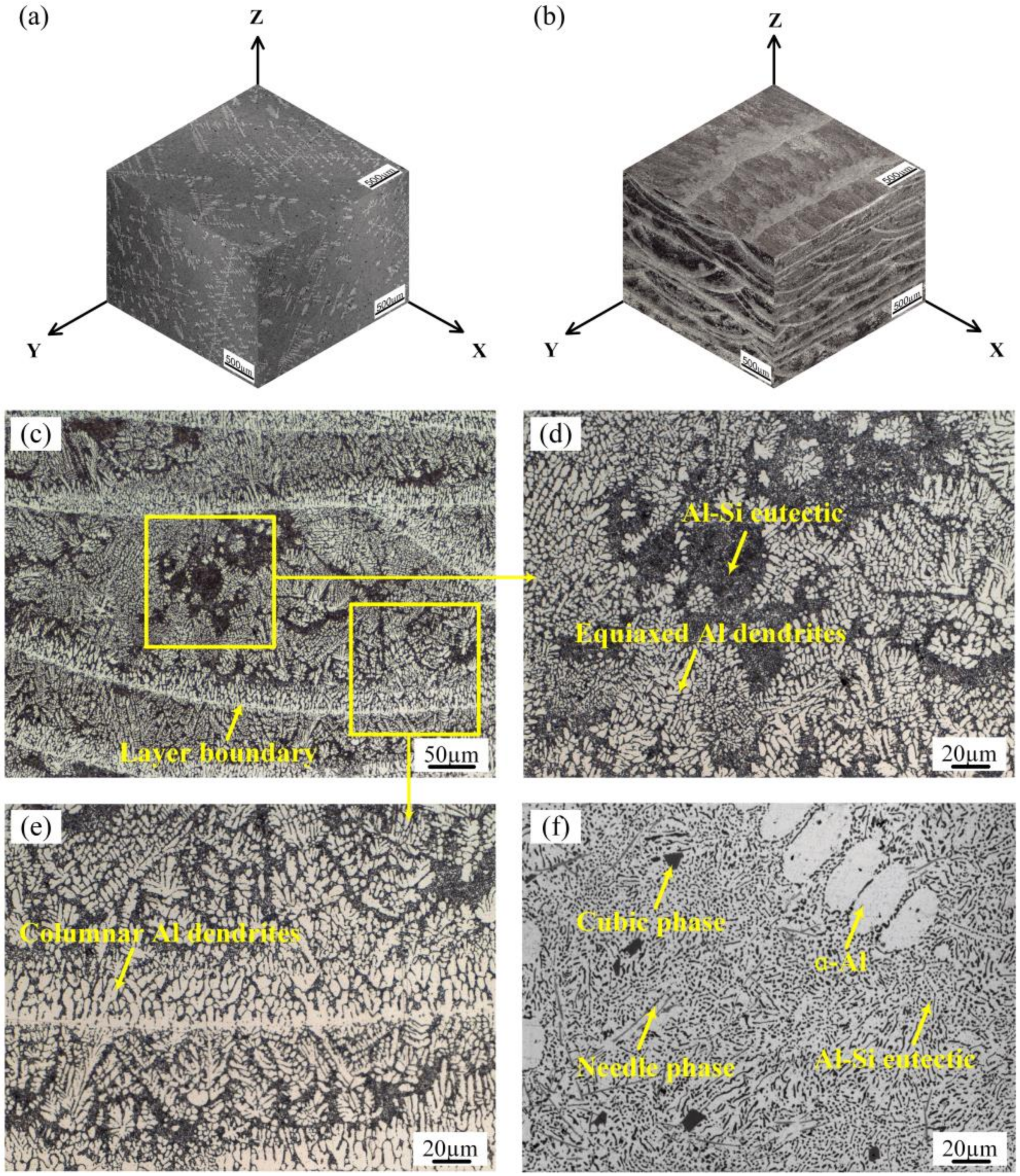
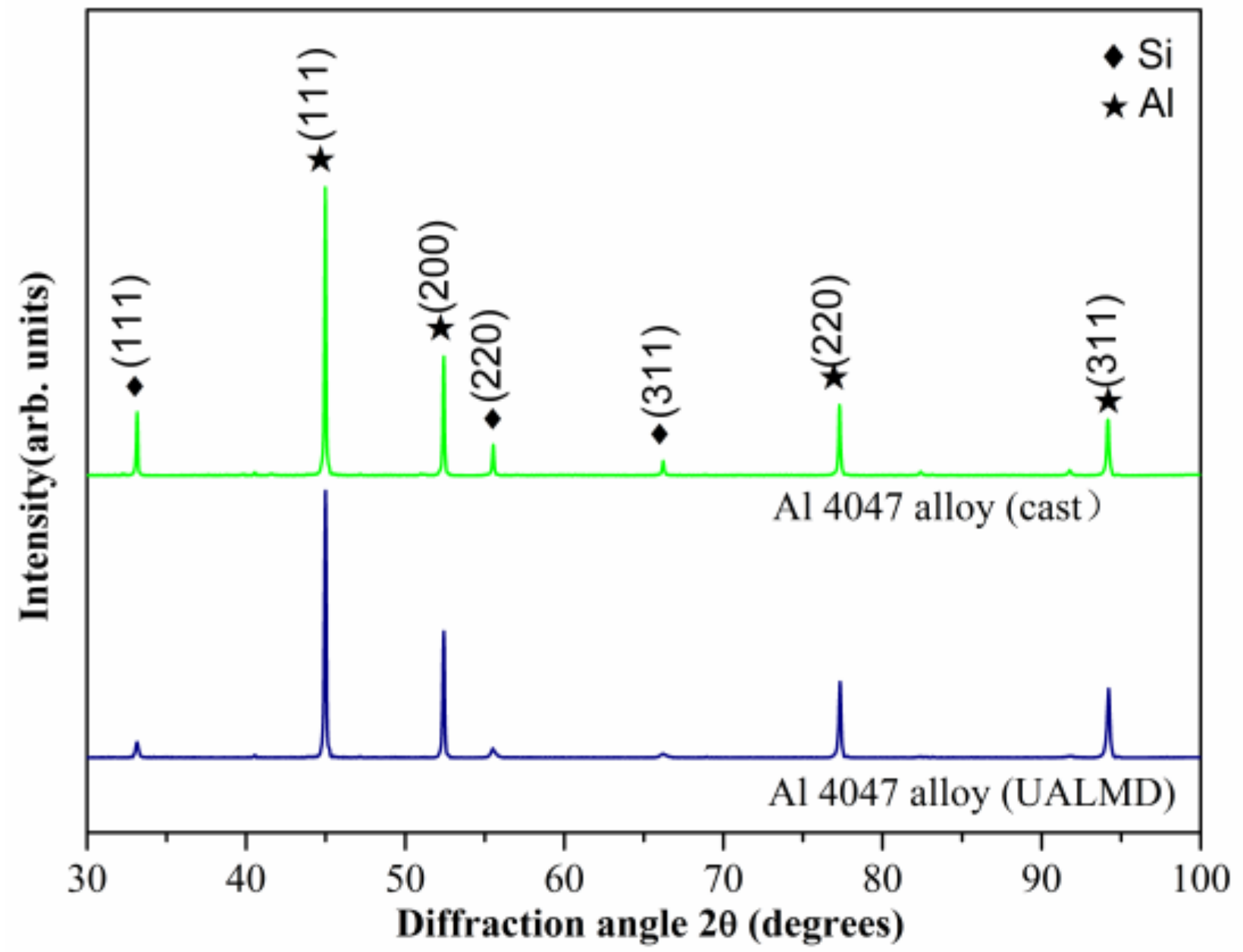
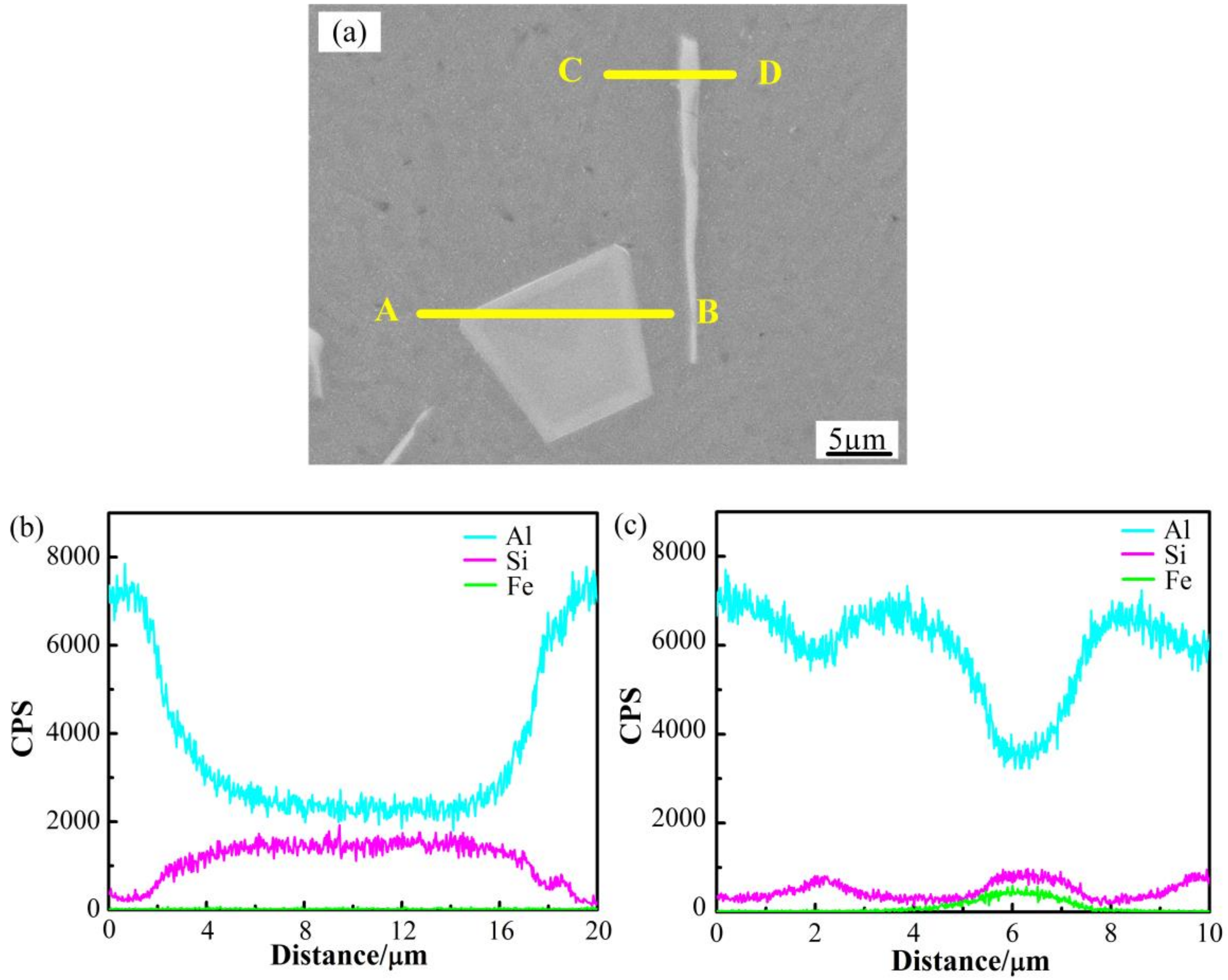
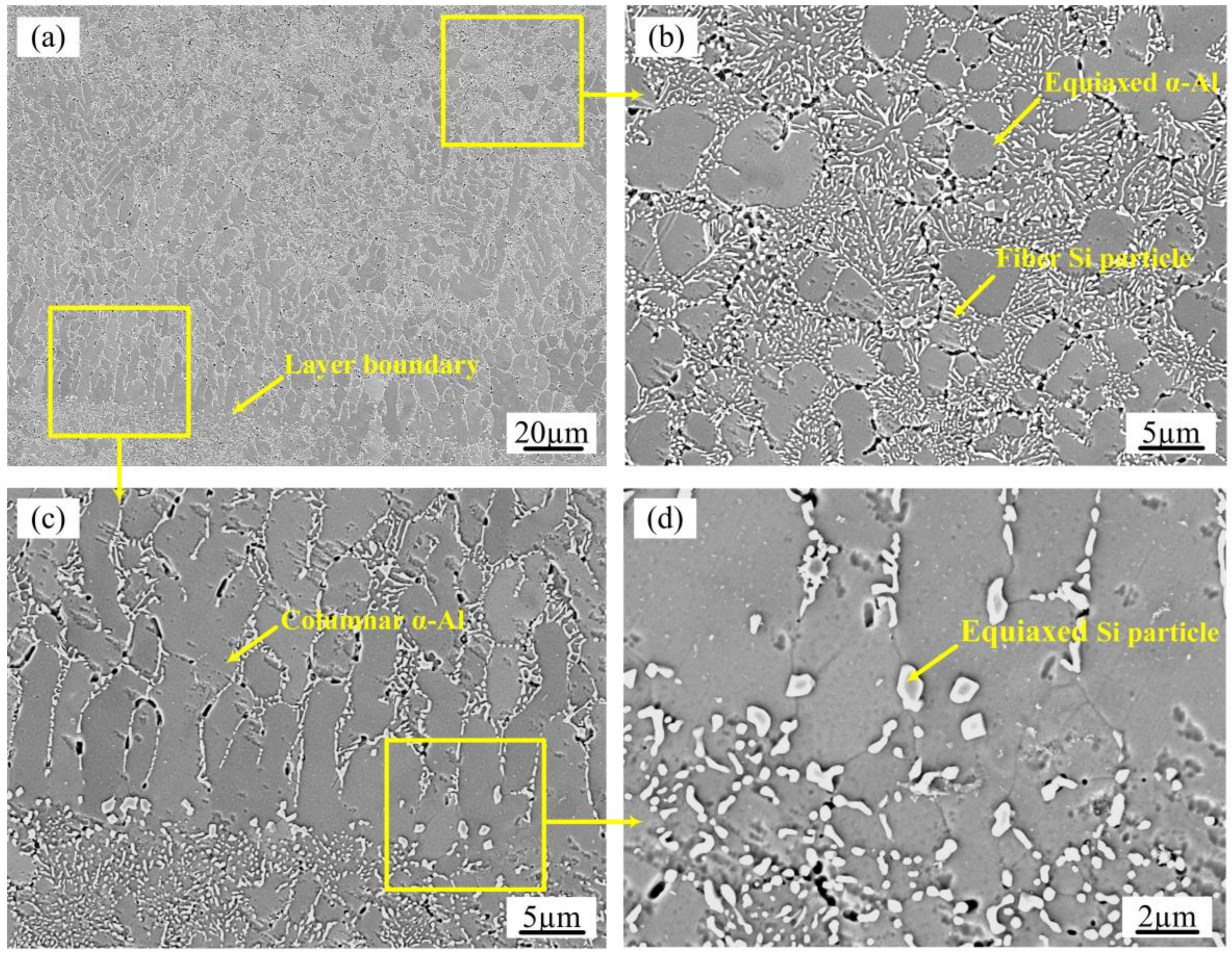
3.2. Microstructural Characterization

Figure 4 shows the macrostructures of the cast and UALMD-optimized samples. Regardless of the preparation process used, the samples primarily consisted of an α-Al solid solution and an Al-Si eutectic structure. In the metallographic photograph, the α-Al solid solution was white and bright, and the Al-Si eutectic structure was dark due to its poor corrosion resistance. Similar to the literature [30], the overall structure of the cast samples was characterized a typical homogeneous hypoeutectic structure. The dispersed primary α-Al dendrites with a size of approximately 15–540 µm and a volume fraction of 11–16 pct were distributed between the continuous Al-Si eutectic structures (Figure 4a). However, the results revealed the presence of approximately 45–55 pct primary α-Al phases in sizes from 10 to 90 µm in the UALMD layer (Figure 4b). The reason for this change was that the eutectic point was biased toward the high silicon concentration side during rapid laser cooling, and the amount of aluminium solid solution was remarkably increased [20].
Due to the characteristics of the laser arc and scanning strategy, the three-dimensional macrostructures of the UALMD-optimized samples were anisotropic. In the XZ and YZ sections, the low-magnification metallographic features had an arc-shaped molten pool structure and strip-like structure alternate with each other. In the XY section, the metallographic structure was featured by parallel strips of material. Amplifying the metallographic structure of the XZ section of the UALMD-optimized sample (Figure 4c), the microstructure was not uniform in the single molten pool. The structure at the center of the molten pool consisted of aluminium equiaxed crystal and an Al-Si eutectic structure (Figure 4d), and the boundary of the molten pool was primarily composed of columnar aluminum crystals (Figure 4e).
Due to the laser heating and cooling rates being faster than the casting process, the temperature gradient (G) and the solidification rate (R) in different positions of the molten pool obtained by the laser deposition method were quite different. Due to the large G and the small R at the boundary of the molten pool, the Al solid solution in the form of columnar crystals tended to grow vertically toward the bead boundary. However, with decreasing of the G and increasing R at the center of the molten pool, the growth rate of Al grains in all directions was consistent, easily forming equiaxed crystals [31].
The XRD patterns of the Al 4047 alloys using two different preparation processes are shown in Figure 5. Only the typical diffraction peaks associated with the Al phase and the Si phase existed, and presence of other intermetallic phases was too low to be detected in the XRD scan. No distinct changes in the position and intensity of the Al Bragg peak were observed in the samples prepared by the casting and UALMD methods. The relative intensity of the Al (111) Bragg peak in all samples was significantly higher than other Al peaks. In addition, compared with the casting method, the Si peak intensity in the UALMD-prepared materials was rather weak, indicating a reduction in the content of free Si caused by the supersaturated solid solubility of silicon in aluminium during the rapid laser solidification process [32].
To distinguish the components of fine cubic phases and needle phases in the metallographic structure of Figure 4f, the SEM microstructural observations and the corresponding elemental distribution along the linear scan of the different phases were examined on the cast samples, as shown in Figure 6. To ensure the accuracy of the line scan component, the specimen was not corroded. According to the metallographic and scanning electron micrographs, the cast structure of Al 4047 alloys consisted of three structured-type phases: an Al phase, Si phase and iron-rich phase. The silicon phase existed in two forms, one of which was a cubic form with a size of 5–35 µm and was discretely distributed in the Al alloys (Figure 6a), and the second type had a coarse rod shape with an aspect ratio of 1:1–1:20 and alternately existed with α-Al platelets in the eutectic structure (Figure 4f). The iron-rich phases were long and needle-like, and the iron originated from the casting process (Figure 6a).
Figure 7 shows the SEM microstructure of the XZ section of the UALMD-prepared samples. The microstructure of the samples was composed of an Al-matrix reinforced with Si particles (Figure 7a). In addition, there were small black voids between the dendrites caused by the removal of the silicon particles during the etching process. Smaller Si with a mean size of <2 µm was obtained in the UALMD-processed sample compared to those samples fabricated by the casting process. The morphology of the Si particles at different regions in the deposited layer of the UALMD-processed samples was nonuniform. The comparatively fine Si particles in the eutectic structure had a fibrous morphology, as shown in Figure 7b. In contrast, the silicon particles were obviously equiaxed and coarsened to 1 to 2 µm along the layer boundary due to the heat treatment of the laser source on the former deposited layer during laser deposition (Figure 7c,d).

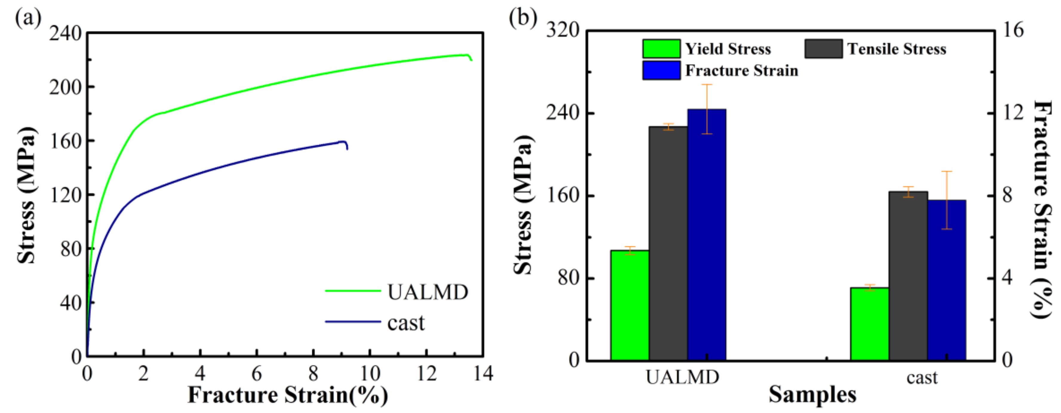
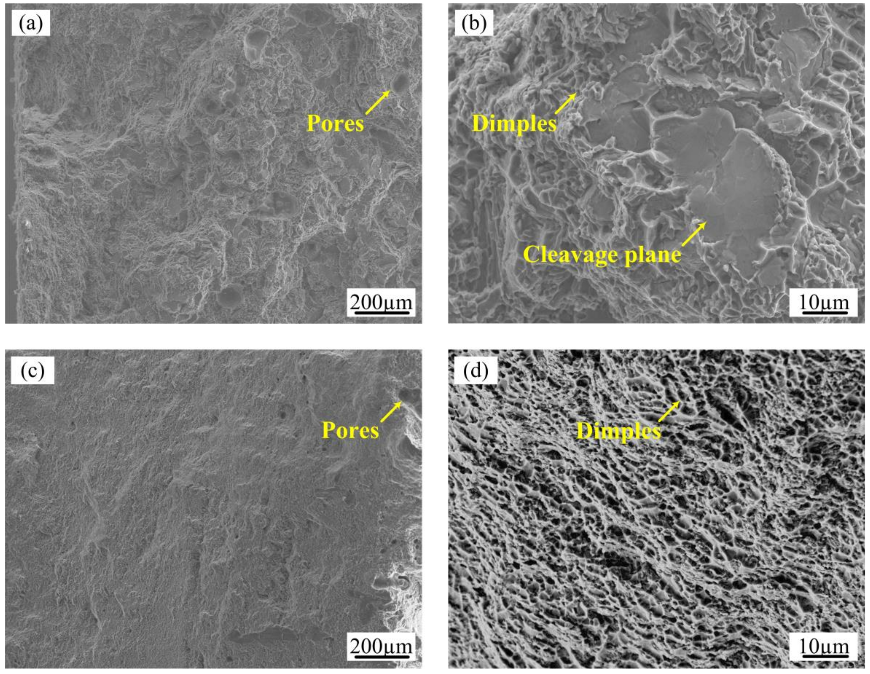
3.3. Tensile Performance

Figure 8 compares the tensile stress-strain curves and tensile properties of casting-processed and UALMD-prepared samples. The cast sample displayed a yield strength (YS) of ~71 ± 3 MPa and an ultimate tensile strength (UTS) of ~164 ± 5 MPa with ~7.8% ± 1.4% strain to failure, which was similar to the results of Suárez et al. [33] for Al-Si eutectic alloys. The tensile results of the samples produced by the UALMD method revealed that the YS rose to ~107 ± 4 MPa and the UTS to ~227 ± 3 MPa, where fracture occurred at 12.2% ± 1.4% strain. The UALMD-produced materials had YS and UTS values approximately 51% and 38% higher than the corresponding value of the cast samples, respectively. In addition, the elongation strain was approximately 1.6 times that of the cast material.
Figure 9 shows SEM images of the fracture surface of the samples obtained by the two preparation methods. The macroscopic fracture of the cast Al-Si alloys was perpendicular to the tensile direction, and no obvious necking occurred during the fracture process. The magnified morphology of the casting fracture displayed many flat quasi-cleavage planes and some dimples (Figure 9b), exhibiting a mixed fracture of brittle fracture and ductile fracture. However, for the UALMD-processed samples, the fracture surface formed a 45° oblique rupture, and the entire enlarged surface of the fracture was uniformly distributed with parabolic dimples (Figure 9d), which was consistent with its improved ductility.
During the tensile process of the Al 4047samples, the main fracture source was initiated from the residual pores on the surface or near the surface of the samples. Since the Si phases were harder than the aluminium matrix, Si particles might hinder the dislocation motion and cause stress concentration, giving rise to the initiation and propagation of the fracture around the pores. Thus, the microvoids caused by the breakage of the Si particles were expanded and connected, leading to the overall fracture of the samples.
Compared with the cast samples, the improvement of mechanical properties obtained by UALMD-processed materials could be attributed to grain refining strengthening and solid solution strengthening due to ultrasonic action and rapid laser cooling. In the UALMD-produced materials, the Si phases were more difficult to fracture and could effectively transfer loads due to their smaller size and fine fibrous or granular type, guaranteeing higher strength compared to the coarse rod or cuboid morphologies in the cast samples. In addition, the effect of iron-rich phases on fracture behavior could be ignored due to their absence in the materials made with the UALMD process. Furthermore, because of the rapid solidification characteristics of the laser, the enhanced strength and ductility of the UALMD-processed samples might also be the result of a supersaturated Si content in the Al matrix and the refined grains of α-Al solid solution.

4. Conclusions

  • As the powder feeding laser power increased, the defects in the deposited layer changed from incomplete fusion to porosity defects. The pores could be almost eliminated by laser remelting treatment and ultrasonic vibration of the same deposit. By optimizing the powder feeding laser power, remelting laser power and ultrasonic power, deposited samples with a maximum density of 99.1% were achieved, which was almost equivalent to the density of the cast samples.
  • Compared with the cast structure, the primary α-Al dendrite grain size of the materials produced by the UALMD method was refined from 15–540 µm to 10–90 µm, while the volume fraction was increased from 11–16% to 45–55% due to the rapid cooling characteristics of the laser and the cavitation effect of the ultrasonic vibration treatment. Moreover, the size and morphology of the Si particles were also transformed from a rod-like or cuboids shape with a size range 1–35 µm in the cast samples to a granular or fibrous shape less than 2 µm in size in the laser deposited materials.
  • Under the ultrasonic-assisted laser deposition optimization process, the ultimate tensile strength, yield strength and elongation of the samples reached 227 ± 3 MPa, 107 ± 4 MPa and 12.2 ± 1.4%, respectively, which were approximately 1.5 times, 1.4 times and 1.6 times the corresponding mechanical properties of the cast alloys. The improvement of the mechanical properties was primarily attributed to the morphological change, size refinement and solid solubility variation of the α-Al dendrites and silicon particles, which led to grain refining strengthening and solid solution strengthening.

Author Contributions

Y.Z. designed the experiments and wrote the paper; Y.C. (Yan Chen) and L.K. were responsible for experimental work and samples preparation; Y.C. (Yabin Cao) and Y.G. contributed to the data processing; H.Q. and S.Y. revised the paper.

Funding

This research was supported by the National Natural Science Foundation of China Major Project grant number 11790282; the National Natural Science Foundation of China grant number 51705344, 51775359; Hebei Normal University Science and Technology Projects grant number QN2015038, QN2016157; and Natural Science Foundation of Hebei Province grant number E2016210107.

Conflicts of Interest

The authors declare no conflict of interest.

References

  1. Singh, A.; Ramakrishnan, A.; Baker, D.; Biswas, A.; Dinda, G.P. Laser metal deposition of nickel coated Al 7050 alloy. J. Alloy. Compd. 2017, 719, 151–158. [Google Scholar] [CrossRef]
  2. Dinda, G.P.; Dasgupta, A.K.; Mazumder, J. Evolution of microstructure in laser deposited Al-11.28%Si alloy. Surf. Coat.Technol. 2012, 206, 2152–2160. [Google Scholar] [CrossRef]
  3. Wei, H.L.; Elmer, J.W.; Debroy, T. Origin of grain orientation during solidification of an aluminum alloy. Acta Mater. 2016, 115, 123–131. [Google Scholar] [CrossRef] [Green Version]
  4. Herzog, D.; Seyda, V.; Wycisk, E.; Emmelmann, C. Additive manufacturing of metals. Acta Mater. 2016, 117, 371–392. [Google Scholar] [CrossRef]
  5. Plotkowski, A.; Rios, O.; Sridharan, N.; Sims, Z.; Unocic, K.; Ott, R.T.; Dehoff, R.R.; Badu, S.S. Evaluation of an Al-Ce alloy for laser additive manufacturing. Acta Mater. 2017, 126, 507–519. [Google Scholar] [CrossRef] [Green Version]
  6. Qin, L.Y.; Men, J.H.; Zhang, L.S.; Zhao, S.; Li, C.F.; Yang, G.; Wang, W. Microstructure homogenizations of Ti-6Al-4V alloy manufactured by hybrid selective laser melting and laser deposition manufacturing. Mater. Sci. Eng. A 2019, 759, 404–414. [Google Scholar] [CrossRef]
  7. Ahmed, N. Direct metal fabrication in rapid prototyping: A review. J. Manuf. Process. 2019, 42, 167–191. [Google Scholar] [CrossRef]
  8. Nam, S.; Cho, H.; Kim, C.; Kim, Y.M. Effect of process parameters on deposition properties of functionally graded STS 316/Fe manufactured by laser direct metal deposition. Metals 2018, 8, 607. [Google Scholar] [CrossRef]
  9. Olakanmi, E.O.; Cochrane, R.F.; Dalgarno, K.W. A review on selective laser sintering/melting (SLS/SLM) of aluminium alloy powders: Processing, microstructure, and properties. Prog. Mater. Sci. 2015, 74, 401–477. [Google Scholar] [CrossRef]
  10. Yang, Y.; Gu, D.D.; Dai, D.H.; Ma, C.L. Laser energy absorption behavior of powder particles using ray tracing method during selective laser melting additive manufacturing of aluminum alloy. Mater. Des. 2018, 143, 12–19. [Google Scholar] [CrossRef]
  11. Thijs, L.; Kempen, K.; Kruth, J.P.; Van Humbeeck, J. Fine-Structured aluminium products with controllable texture by selective laser melting of Pre-Alloyed AlSi10Mg powder. Acta Mater. 2013, 61, 1809–1819. [Google Scholar] [CrossRef]
  12. Bhuiyan, M.S.; Tada, Y.; Toda, H.; Hang, S.; Uesugi, K.; Takeuchi, A.; Sakaguchi, N.; Watanabe, Y. Influences of hydrogen on deformation and fracture behaviors of high Zn 7XXX aluminum alloys. Int. J. Fract. 2016, 200, 13–29. [Google Scholar] [CrossRef]
  13. Rao, H.; Giet, S.; Yang, K.; Wu, X.H.; Davies, C.H.J. The influence of processing parameters on aluminium alloy A357 manufactured by selective laser melting. Mater. Des. 2016, 109, 334–346. [Google Scholar] [CrossRef]
  14. Marchese, G.; Aversa, A.; Lorusso, M.; Manfredi, D.; Calignano, F.; Lombardi, M.; Biamino, S.; Pavese, M. Development and characterisation of aluminium matrix nanocomposites AlSi10Mg/MgAl2O4 by laser powder bed fusion. Metals 2018, 8, 175. [Google Scholar] [CrossRef]
  15. Wang, X.J.; Zhang, L.C.; Fang, M.H.; Sercombe, T.B. The effect of atmosphere on the structure and properties of a selective laser melted Al-12Si alloy. Mater. Sci. Eng. A 2014, 597, 370–375. [Google Scholar] [CrossRef]
  16. Read, N.; Wang, W.; Essa, K.; Attallah, M.M. Selective laser melting of AlSi10Mg alloy: Process optimisation and mechanical properties development. Mater. Des. 2015, 65, 417–424. [Google Scholar] [CrossRef] [Green Version]
  17. Yu, G.Q.; Gu, D.D.; Dai, D.H.; Xia, M.J.; Ma, C.L.; Chang, K. Influence of processing parameters on laser penetration depth and melting/re-melting densification during selective laser melting of aluminum alloy. Appl. Phys. A 2016, 122, 891. [Google Scholar] [CrossRef]
  18. DebRoy, T.; Wei, H.L.; Zuback, J.S.; Mukherjee, T.; Elmer, J.W.; Milewski, J.O.; Beese, A.M.; Wilson-Heid, A.; De, A.; Zhang, W. Additive manufacturing of metallic Components—Process, structure and properties. Prog. Mater. Sci. 2018, 92, 112–224. [Google Scholar] [CrossRef]
  19. Karnati, S.; Zhang, Y.L.; Liou, F.F.; Newkirk, J.W. On the feasibility of tailoring Copper-Nickel functionally graded materials fabricated through laser metal deposition. Metals 2019, 9, 287. [Google Scholar] [CrossRef]
  20. Dinda, G.P.; Dasgupta, A.K.; Bhattacharya, S.; Natu, H.; Dutta, B.; Mazumder, J. Microstructural Characterization Of Laser-Deposited Al 4047 Alloy. Metall. Mater. Trans. A 2013, 44, 2233–2242. [Google Scholar] [CrossRef]
  21. Zhao, T.; Cai, W.C.; Dahmen, M.; Schaible, J.; Hong, C.; Gasser, A.; Weisheit, A.; Biermann, T.; Kelbassa, I.; Zhang, H.; et al. Ageing response of an Al-Mg-Mn-Sc-Zr alloy processed by laser metal deposition in Thin-Wall structures. Vacuum 2018, 158, 121–125. [Google Scholar] [CrossRef]
  22. Lv, F.; Shen, L.; Liang, H.X.; Xie, D.Q.; Wang, C.J.; Tian, Z.J. Mechanical properties of AlSi10Mg alloy fabricated by laser melting deposition and improvements via heat treatment. Optik 2019, 179, 8–18. [Google Scholar] [CrossRef]
  23. Li, J.W.; Momono, T.; Tayu, Y.; Fu, Y. Application of ultrasonic treating to degassing of metal ingots. Mater. Lett. 2008, 62, 4152–4154. [Google Scholar] [CrossRef]
  24. Puga, H.; Barbosa, J.; Seabra, E.; Ribeiro, S.; Prokic, M. The influence of processing parameters on the ultrasonic degassing of molten AlSi9Cu3 aluminium alloy. Mater. Lett. 2009, 63, 806–808. [Google Scholar] [CrossRef]
  25. Xu, H.B.; Han, Q.Y.; Meek, T.T. Effects of ultrasonic vibration on degassing of aluminum alloys. Mater. Sci. Eng. A 2008, 473, 96–104. [Google Scholar] [CrossRef]
  26. Han, Q.; Viswanathan, S. Hydrogen evolution during directional solidification and its effect on porosity formation in aluminum alloys. Metall. Mater. Trans. A 2002, 33, 2067–2072. [Google Scholar] [CrossRef]
  27. Das, S. Physical aspects of process control in selective laser sintering of metals. Adv. Eng. Mater. 2003, 5, 701–711. [Google Scholar] [CrossRef]
  28. Li, Z.W.; Xu, Z.W.; Ma, L.; Wang, S.; Liu, X.S.; Yan, J.C. Cavitation at filler metal/substrate interface during Ultrasonic-Assisted soldering. Part I: Cavitation characteristics. Ultrason. Sonochem. 2018, 49, 249–259. [Google Scholar] [CrossRef]
  29. Wang, F.; Tzanakis, I.; Eskin, D.; Mi, J.; Connolley, T. In situ observation of ultrasonic Cavitation-Induced fragmentation of the primary crystals formed in Al alloys. Ultrason. Sonochem. 2017, 39, 66–76. [Google Scholar] [CrossRef]
  30. Prashanth, K.G.; Scudino, S.; Klauss, H.J.; Surreddi, K.B.; Löber, L.; Wang, Z.; Chaubey, A.K.; Kühn, U.; Eckert, J. Microstructure and mechanical properties of Al-12Si produced by selective laser melting: Effect of heat treatment. Mater. Sci. Eng. A 2014, 590, 153–160. [Google Scholar] [CrossRef]
  31. Roberts, I.A.; Wang, C.J.; Esterlein, R.; Stanford, M.; Mynors, D.J. A Three-Dimensional finite element analysis of the temperature field during laser melting of metal powders in additive layer manufacturing. Int. J. Mach. Tools Manuf. 2009, 49, 916–923. [Google Scholar] [CrossRef]
  32. Ma, P.; Prashanth, K.G.; Scudino, S.; Jia, Y.D.; Wang, H.W.; Zou, C.M.; Wei, Z.J.; Eckert, J. Influence of annealing on mechanical properties of Al-20Si processed by selective laser melting. Metals 2014, 4, 28–36. [Google Scholar] [CrossRef]
  33. Suárez-Peña, B.; Asensio-Lozano, J. Microstructure and mechanical property developments in Al-12Si gravity die casting after Ti and/or Sr additions. Mater. Charact. 2006, 57, 218–226. [Google Scholar] [CrossRef]
Figure 1. Schematic illustrations of ultrasonic-assisted laser metal deposition: (a) experimental device; and (b) deposited layer size and scan path.
Metals 09 01111 g001aMetals 09 01111 g001b
Figure 2. Metallographic images of the XZ section and plot showing the effect of powder feeding laser power on the relative density.
Metals 09 01111 g002
Figure 3. Optical images of the XZ section and curve of relative density versus remelting laser powers.
Metals 09 01111 g003
Figure 4. OM micrographs of the Al 4047samples: (a) 3D microstructure built by casting; (b) 3D microstructure built by the ultrasonic-assisted laser metal deposition UALMD; (c) amplifying the metallographic structure of the XZ section in 4b; (d) the equiaxed dendrite near the top of the layer; (e) the columnar dendrite at the bottom of the layer; and (f) amplification of the metallographic structure in 4a.
Metals 09 01111 g004
Figure 5. XRD patterns of the Al 4047 alloys produced using casting and UALMD processes.
Metals 09 01111 g005
Figure 6. SEM micrographs and corresponding elemental distribution along lines in the cast Al 4047 samples: (a) SEM micrograph; (b) element distribution along line of AB in 6a; and (c) element distribution along line of CD in 6a.
Metals 09 01111 g006
Figure 7. SEM microstructures showing the morphology of Si at different locations in the samples produced by UALMD: (a) low magnification micrograph of the deposited layer; (b) Si in the eutectic structure of the molten pool; and (c,d) Si along the layer boundary.
Metals 09 01111 g007
Figure 8. Tensile test results of Al 4047 alloys prepared by casting and UALMD process: (a) stress-strain curve; and (b) tensile characteristic histograms.
Metals 09 01111 g008
Figure 9. SEM photographs of the fracture surface of the tensile test: (a,b) overview and magnified images of the casting material; and (c,d) overview and magnified images of the UALMD-processed material.
Metals 09 01111 g009
Table 1. Varied process parameters (W).
Sample No.The Powder Feeding Laser Power (Pw)The Remelting Laser Power (Pr)The Ultrasonic Vibration Power (Pu)
170000
290000
3110000
4130000
5150000
611007000
711009000
8110011000
9110013000
1011001100400
1111001100700
12110011001000
Table 2. Fixed process parameters.
Scan Speed (mm/min)Powder Flow Rate (gm/min)Hatch Distance (mm)Layer Thickness (µm)Ultrasonic Frequency (kHz)
3601.2130020
Table 3. Relative density values at different ultrasonic vibration powers.
The Ultrasonic Vibration Power (W)04007001000
Relative density value (%)97.2 ± 0.897.4 ± 0.598.0 ± 0.898.2 ± 0.9

