Article

External Connection versus Internal Connection in Dental Implantology. A Mechanical in vitro Study

by
Ignacio Fernández-Asián
1,
Álvaro Martínez-González
2,
Daniel Torres-Lagares
1,
María-Ángeles Serrera-Figallo
1,* and
José-Luis Gutiérrez-Pérez
1
1
Faculty of Dentistry, University of Seville, 41009 Seville, Spain
2
ICEMM S.L.U., 8. Oficina 0-08, Edificio Antares, Calle las Fábricas, 28923 Madrid, Spain
*
Author to whom correspondence should be addressed.
Metals 2019, 9(10), 1106; https://doi.org/10.3390/met9101106
Submission received: 16 August 2019 / Revised: 26 September 2019 / Accepted: 13 October 2019 / Published: 15 October 2019

Abstract

:
(1) Background: In today’s dentistry, implantology has become a therapeutic resource of choice in certain clinical situations. The design of implants has evolved in several aspects since their inception. Dental implants were initially designed with an external hex connection, although due to force transmission and security in the adjustment of the prosthesis, later implants featured an internal hex connection. This study aims to analyse the mechanical properties of two types of implants (an internal connection and an external connection) from the same manufacturer and their different prosthetic components (union screw between implant and prosthetic abutment, and the abutment itself) when subjected to different types of load. (2) Materials and methods: Intraosseous dental implants of similar shape, design and size, although different in type of connection (external vs. internal), were studied. The specifications of the UNI EN ISO 14801 test standard were used, with all determinations being carried out three times. Finally, the dimensional characterisation of the samples analysed after the dynamic load study was carried out, and the values of both study groups were compared by means of the non-parametric Mann–Whitney U test to find statistically significant differences (p < 0.05). (3) Results: For the static characterisation test, we found between 610.9 N and 986.1 N for the external connection and between 1263.6 N and 1324 N for the internal connection (p = 0.011). All of the dynamic load tests were positive and there was no failure in any of the components studied. (4) Conclusions: After the analysis of the samples studied in vitro, satisfactory results were obtained, demonstrating that both connections can support considerable mechanical loads according to international standards (UNI EN ISO 14801).

1. Introduction

In today’s dentistry, implantology has become a therapeutic resource of choice in certain clinical situations. With a high success rate, implant placement has become a daily practice in dental clinics [1,2,3].
However, implantology is not without its complications, which can affect both the biological level (bone loss, infection, soft tissue alterations) and the mechanical level (fracture of the implant or any of its components) [4,5,6]. Once the osseointegration phase is over, complications related to mechanics become one of these possible complications; among them we can find, for example, fracture of the implant or of one of its prosthetic attachments, possibly resulting from the implant being subjected to an excess of loads in the oral cavity [7]. This may arise due to certain biomechanical problems that should have been detected previously in preclinical trials.
Dental implants were initially designed with an external hex connection in 1985 [8], but subsequently, due to the analysis of a series of mechanical problems, among other factors, implants with an internal hex connection appeared. Paradoxically, however, some authors have demonstrated that each type of connection has several advantages and disadvantages over the other [9,10].
Some of the advantages of external connection implants are that they simplify the prosthetic phase by exhibiting better passive fit and greater versatility in the case of multiple implants; however, they present a worse distribution of forces under certain types of loads. All of the above may lead to a worse biological behaviour, due to a worse distribution of forces and a higher concentration in certain areas, which would affect bone metabolism [11,12]. Internal connection, on the other hand, has the opposite qualities and disadvantages, exhibiting a more homogeneous distribution of the load, but a worse passive fit in the face of multiple rehabilitations, which develops into an increase in the complexity of the prosthesis [13,14].
Although the matter of the type of connection of the implant may seem to have been largely resolved in favour of the internal connection, at least in biological terms—as has already been mentioned—the external connection is still used due to its various advantages, and even recent studies support the use of this type of connection, as they argue that there are no clinical benefits of one connection over another [11,15].
Nevertheless, a series of common complications may appear in both external and internal connections, such as the loosening (and possibly fracture) of the union screw between the implant and the prosthetic abutment, as well as the plastic deformation of the materials (implant-abutment set) [16]. The following study aims to analyse the mechanical properties of two types of implants (an internal connection and an external connection) and their different prosthetic components (union screw between implant and prosthetic abutment, and the abutment itself) when subjected to different types of load.

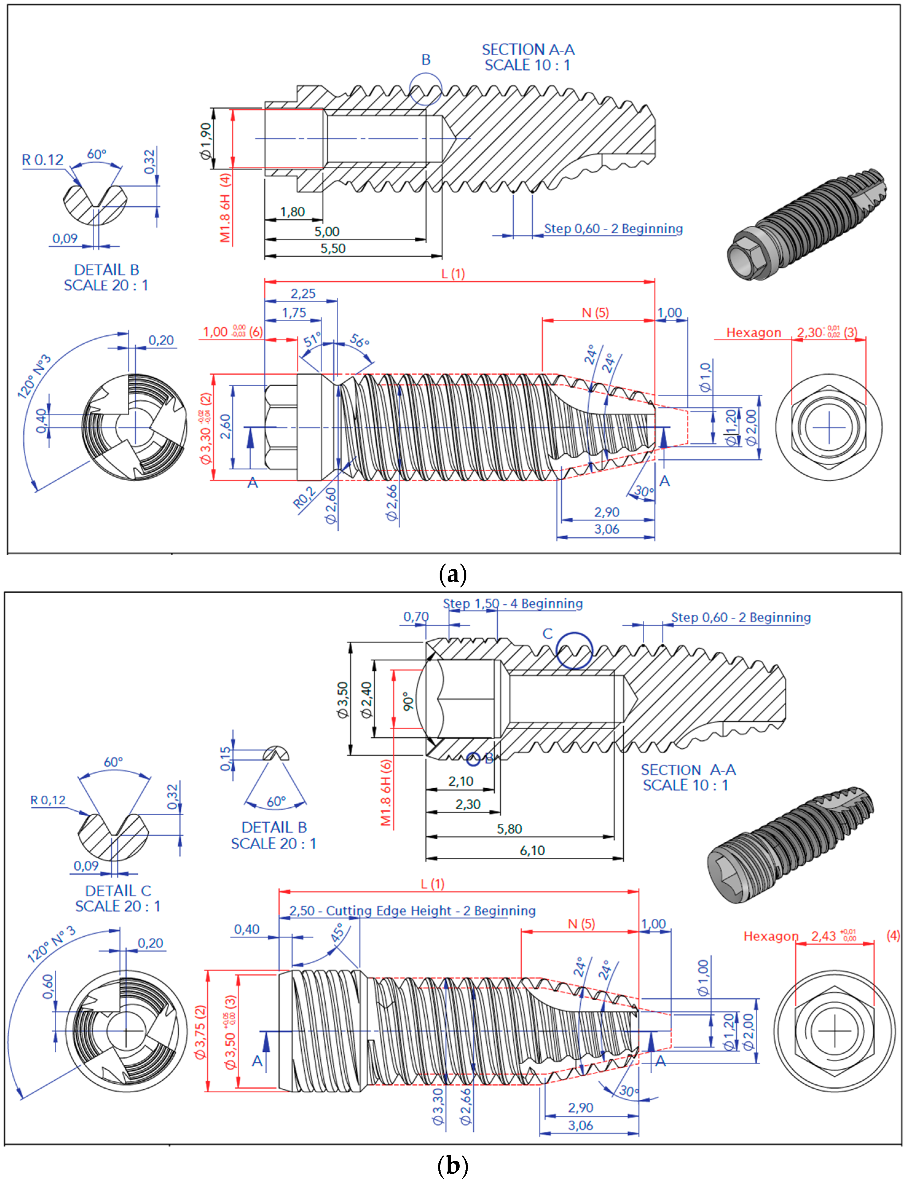
2. Materials and Methods

In the trial, conical intraosseous dental implants by the brand Oxtein (Zaragoza, Spain) were taken as a sample (Figure 1). The macroscopic design and size of the implants were similar. Models L6 and L35 (Oxtein, Spain) were used in their 3.3 mm diameter and 14.5 mm length versions. Both implants were made of titanium (Grade V ELI-2 for L35 and cold worked, Grade IV for L6). The study groups were differentiated by the connection used. In the internal connection group, an internal hex connection with a diameter of 3.5 mm was used, while in the external connection group, a hex connection with a height of 0.7 mm and a diameter of 2.7 mm was used (Table 1).
UNI EN ISO 14801 was the test standard applied [17]. This standard determines that the samples be mounted on a cylindrical support structure, with 3 mm of the implant left outside of this support. On this implant, an 8 mm-high cap that will receive the forces with a 30-degree angulation is mounted (Figure 2 and Figure 3). A series of tests (static, dynamic and dimensional characterisation) were carried out on this support structure and experimental set-up.

2.1. Static Characterisation

In order to carry out this test, a uniaxial Italsigma FPF (Italsigma SRL, Forli, Italy) static and dynamic testing machine with an AeP TC4500 5 kN load cell with a maximum capacity of 5 kN and class 0.5 UNI EN ISO 7500-1 was used. The application of the load was produced using a system capable of eliminating the lateral links generated during the test and using the appropriate centring systems; the distance between the load surface and the load cell was 50 mm (Figure 4). Further to this, the test was performed by prefixing the parameters at a test speed of 0.2 mm/min and a preload of 2 N. The temperature at which the different tests were analysed remained within the range of 20 °C ± 5 °C for all the implants studied (number of assays: n = 3 and n = 3), leading to fracture or permanent deformation for the highest acceptable load.

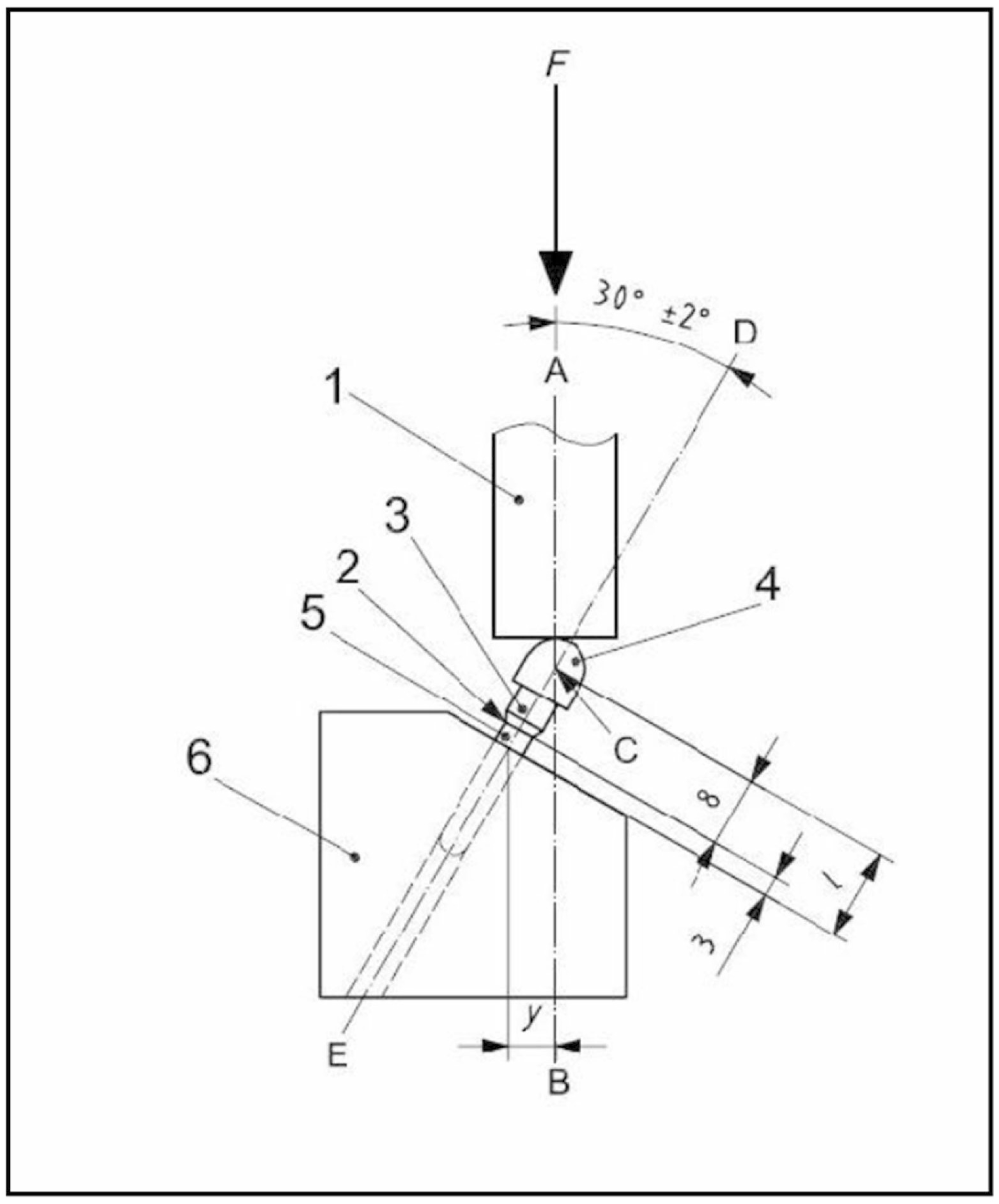
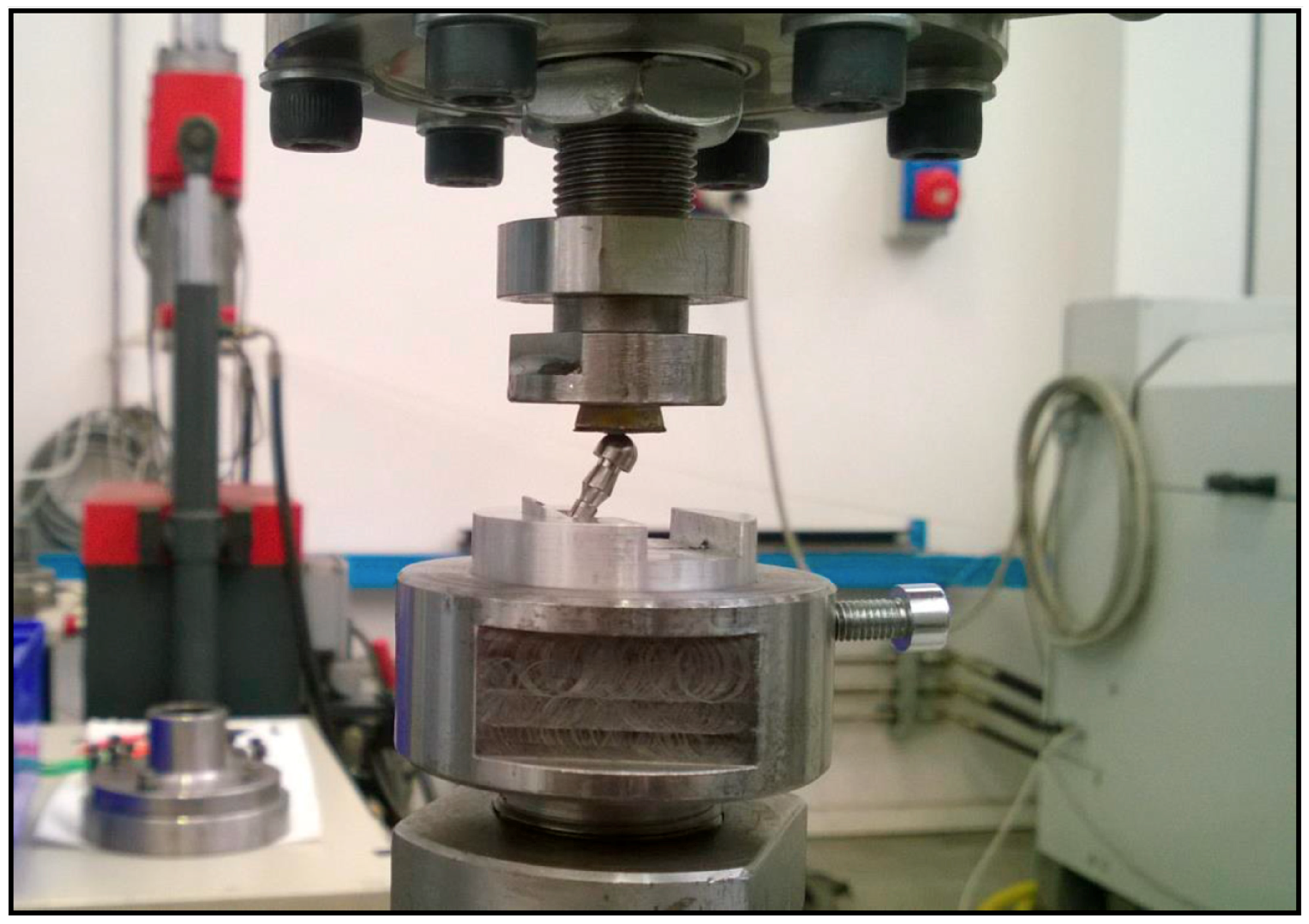
2.2. Characterisation with Dynamic Load

UNI EN ISO 14801 determines that the load to be applied in the dynamic stress test is calculated with respect to the result obtained from a static test carried out with the same loading scheme (Figure 2, Figure 3 and Figure 4). Subsequently, once the static test had been carried out and in order to carry out the dynamic stress test, as mentioned above, the uniaxial testing machine Italsigma FPF was used for static and dynamic tests, with the same configuration that had been used for the static characterisation. The UNI EN ISO 14801 standard also determines that the values of the amplitude of load to be applied to the test are obtained from static tests carried out on samples of the same type. In relation to the way in which the load is performed, these are referred to in the ISO standard as the most harmful situations from a biological perspective: oblique loads with an important lateral component, and assuming a loss of two millimeters in the cortical. All this to ensure that the product can work properly even in the most inadequate biological conditions.
The tests were carried out by controlling the load according to sinusoidal law, with an infinite-length limit set at 5,000,000 cycles. The applied load was set to 10% of the maximum load allowed in the static load experiment.
The test would be considered passed if the component did not present structural defects and/or permanent deformations on the surface of the spherical cap; at the same time, it should also be emphasised that the load button must not have been collapsed and/or worn down. The temperature at which the different tests were analysed remained within the range of 20 °C ± 5 °C for all the implants studied (number of assays: n = 3 and n = 3).

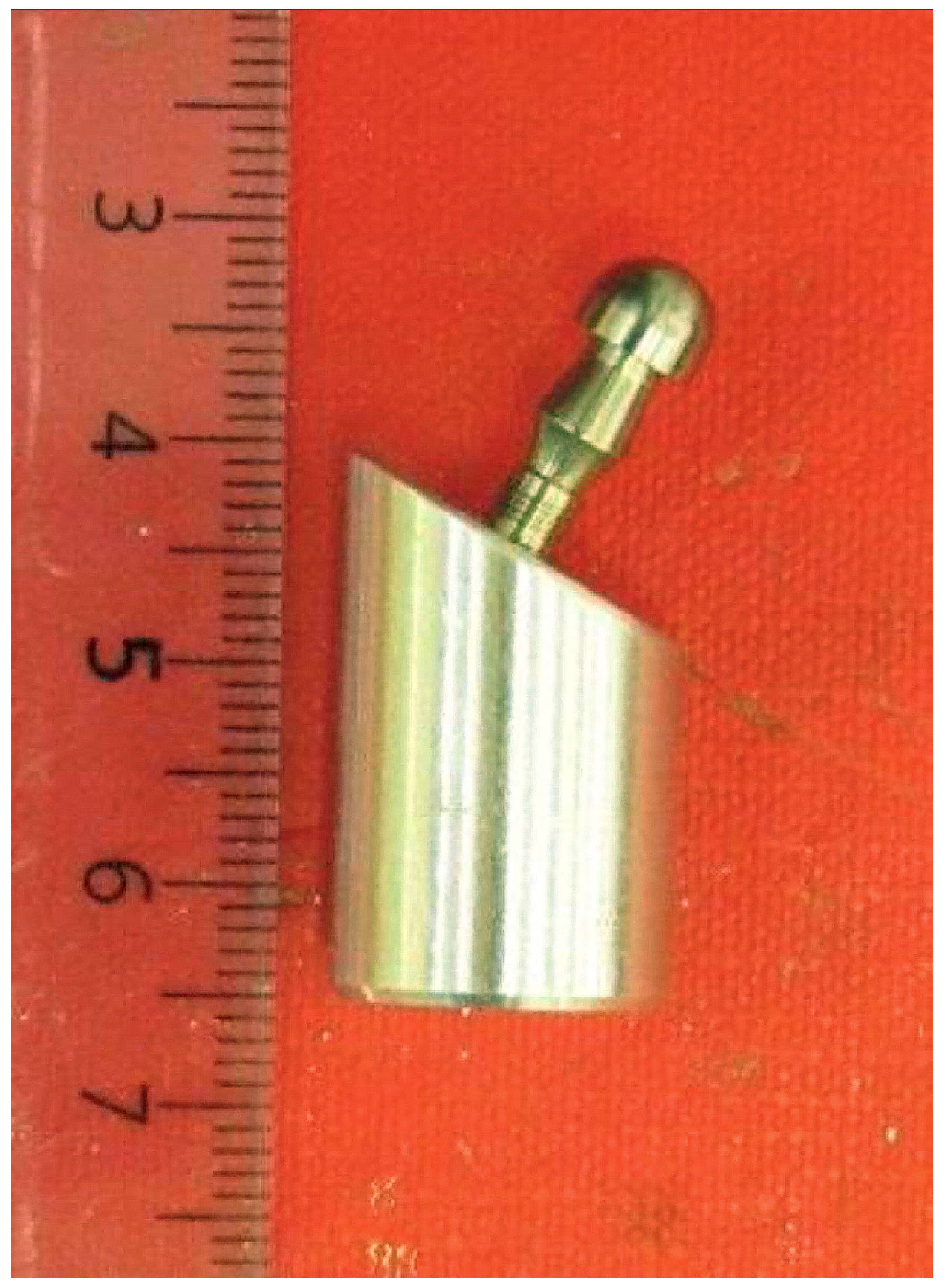
2.3. Dimensional Characterisation after the Dynamic Load Study

In order to evaluate the bending moment and the compression load applied during the tests carried out on the samples under examination, it was necessary to characterise them dimensionally. Using the dimensional parameters measured on the components that passed the test and that are described in the following section, it is possible to determine the applied bending moment during the tests. The bending moment is understood as a moment of force resulting from a distribution of stresses on a cross-section of a bent prismatic test piece or a plate perpendicular to the longitudinal axis along which the bending occurs. The compression load is the load that produces the stress to which a body is subjected by the application of forces that act in the same direction, and tend to shorten it.

2.4. Statistical Analysis

The values of both study groups were compared by means of the non-parametric Mann-Whitney U test to find statistically significant differences (p < 0.05).

3. Results

3.1. Static Characterisation

For each implant connection (internal and external), the static characterisation test was performed on three implants. Higher resistance results were observed in the internal connection, compared to the external one (Table 2). Values were between 610.9 N and 986.1 N for the external connection and between 1263.6 N and 1324 N for the internal connection (these results were statistically significant (p = 0.011)).

3.2. Dynamic Stress Characterisation

After carrying out the tests, dynamic stress characterisation was carried out by controlling the load according to sinusoidal law, with an infinite-length limit set at 5,000,000 cycles. The minimum stimulus was set to 10% of that allowed in the static load experiment (Table 2). The test was considered passed because none of the analysed components presented structural defects or deformations after the tests. In addition, the load button was also analysed, and it did not present any type of collapse and/or wear.

3.3. Dimensional Characterisation

Results obtained in the dimensional characterisation were quite relevant. Average bending moment values were 898.26 ± 6.00 Nmm for the external connection and 604.10 ± 16.50 Nmm for the internal connection. Compression stimulus values were 142.53 ± 0.15 N for the external connection and 94.93 ± 0.45 N for the internal connection (Table 3).
Both the differences between the values described for both groups for the bending moment and the compression stimulus were statistically significant (p < 0.001), providing better biomechanical properties to the internal connection versus the internal connection. However, other data showed no statistical significance (maximum force, length, distance and angle) between the internal and external connection.

4. Discussion

This study aims to compare the mechanical behaviour of the internal connection to that of the external connection in the case of dental implants. In this regard, the comparison of two types of implants from the same manufacturer is a strong point, given that it is an effective measure to control biases related to the manufacturing process, which is shared by both types of sample.
The mechanical strength of an implant system is closely related to the relationship between the implant and its different prosthetic attachments [18,19]. One of the most frequent problems that can be found is the loosening and fracture of the union screw between implant and abutment [20]. This type of problem is often due to several factors, including the design of the implant, the type of interface between implant and abutment, and the load distribution to which it is subjected. Because of the foregoing, it could be said that, in order to decrease this type of complication, the diameter of the implant that will be used should be increased as much as possible, and the design of the implant–abutment junction should have greater resistance to different loads [21,22,23]. However, there is currently no specific design with proven effectiveness when compared to the other connections; therefore, a large number of configurations can be found in the market, which becomes a subject of great debate [24].
In the present study, an in vitro analysis of an implant system was performed (Oxtein, Zaragoza, Spain). The selected implants have a conical implant body design, and both internal and external hex connections. The test method adopted for this in vitro study, as discussed above, was in accordance with UNI EN ISO 14801 standards, which appear to be extremely effective in predicting the mechanical reliability of the relationship between implant and prosthetic abutment.
The implant models selected for the present study are representative of the most common and current types of implant macro and micro-design. We have found it interesting to contrast implants with opposing characteristics, trying to isolate or minimize the possible biases related to other characteristics, looking for two models as similar as possible, even sharing the same manufacturer.
The L6 implant and the L35 implant share the same shape (cylindrical), the same apical profile and the same thread pitch; their major differences are found in the cervical part of the implant, mainly due to the change of platform that each of these models presents.
Within the external connection, the hexagon used by Branemark at the beginning of the implantology is the referent of this type of connection, therefore, this platform has been chosen to represent the external connection. In the case of the internal connection, there are several formats (morse cone, octagon, hexagon, etc.). We have chosen the hexagon to be able to compare similar geometries, which differ in whether they move towards the inside of the implant (internal) or to its exterior (external) [25]. That is, we look for the most similar comparison groups, except for the internal or external connection. Of course, this choice can be debated and other comparisons can be equally interesting and worth studying.
UNI EN ISO 14801 standards suggest a 100% survival rate of those implant-abutment complexes that are subjected to a sinusoidal load with a value of 10% of the maximum load allowed in the static load experiment as an indispensable requirement to be fulfilled; this was optimally fulfilled in the present study.
With respect to the analysis of the results according to the type of connection, several studies have shown that the external hex connection does not stabilise the joint against lateral loads, but instead there is an important stress concentration component that has a significant impact on the fatigue behaviour of the union screw, which results in a greater number of prosthetic complications [26,27]. On the other hand, in the case of the internal hex connection, it has been demonstrated that the transference of the loads towards the interior of the implant avoids excessive loading on the screw, which affects the connection and the union screw less, and thus results in a lower incidence of complications [14,28].
There are articles that indicate that the prosthetic screws in the internal connection, not in an internal hexagon format but with a morse cone, could be more sensitive to prosthetic loading at high loads than the prosthetic screws of an external hexagon [29].
In this trial, highly satisfactory results were collected for both external and internal hex connections. However, it should be noted that the internal hex connection presented better properties than the external one, with the results obtained being very statistically significant (p < 0.001).
There are a large number of brands, producing both implants and prosthetic attachments. Each of them is characterized by materials, manufacturing processes and quality systems specific to each of them, which can influence the final behavior of the product, always respecting certain limits that allow its clinical application. Our study sought to minimize these biases by comparing two products linked to the same manufacturing and quality control processes, since they are manufactured by the same brand. Obviously, this bias control increases the strength of the study to compare the central variable (the type of connection), although it decreases the extension of the results to other situations or brands. Possibly, at the clinical level, it would be more interesting to compare several brands, but inevitably, other biases would enter into competition, which would interfere with the discussion of the results obtained.
In this way, it should be noted that when evaluating the results obtained in the present study, these should be analysed and compared with other studies that supply the intensity of the masticatory forces to which these implants would be subjected in the buccal cavity. For this reason, we can observe how several studies suggest that the area that is most subject to occlusal forces is the first molar region (216–847 N). The anterior area is the one less subject to loads, reaching between a third and a quarter of the force to which the posterior area is subjected (108–299 N) [30,31].
In this study, values of 787 N for the external connection and 1288 N for the internal connection have been recorded in the static test. Therefore, there were adequate results to support both mandibular and maxillary requests in the anterior and posterior regions. For the dynamic test, results between 259 and 172 N were obtained; these values are similar to those obtained in other studies with other implant systems [32].

5. Conclusions

In conclusion, after the in vitro analysis of the Oxtein implant system, satisfactory results were obtained, demonstrating that it can support considerable mechanical loads according to international standards (UNI EN ISO 14801). The internal connection showcased better results than the external connection, although both connections passed the test satisfactorily. For the static characterisation test, we found to be acceptable to withstand loads between 610.9 N and 986.1 N for the external connection and between 1263.6 N and 1324 N for the internal connection (p = 0.011). All of the dynamic load tests were positive and there was no failure in any of the components studied.

Author Contributions

Conceptualization, I.F.-A., D.T.-L. and M.-A.S.-F.; investigation, I.F.-A., D.T.-L. and M.-A.S.-F.; methodology, D.T.-L., M.-A.S.-F. and J.-L.G.-P.; supervision, A.M.-G. and J.-L.G.-P.; Writing—original draft, I.F.-A., A.M.-G., D.T.-L. and J.-L.G.-P.; writing—review & editing, I.F.-A., A.M.-G., D.T.-L., M.-A.S.-F. and J.-L.G.-P.

Funding

This research received no external funding.

Conflicts of Interest

The authors declare no conflict of interest.

References

  1. Holm-pedersen, P.; Lang, N.P.; Müller, F. What are the longevities of teeth and oral implants? Clin. Oral Implant. Res. 2007, 18, 15–19. [Google Scholar] [CrossRef] [PubMed]
  2. Bogaerde, L.V.; Rangert, B.; Wendelhag, I. Immediate/early function of Bränemark System TiUnite implants in fresh extraction sockets in maxillae and posterior mandibles: An 18-month prospective clinical study. Clin. Implant. Dent. Relat. Res. 2005, 7, S121–S130. [Google Scholar] [CrossRef]
  3. Cornelini, R.; Cangini, F.; Covani, U.; Wilson, Jr.; Thomas, G. Immediate restoration of implants placed into fresh extraction sockets for single-tooth replacement: A prospective clinical study. Int. J. Periodontics Restor. Dent. 2005, 25, 439–447. [Google Scholar] [CrossRef]
  4. Chrcanovic, B.R.; Martins, M.D.; Wennerberg, A. Immediate placement of implants into infected sites: A systematic review. Clin. Implant. Dent. Relat. Res. 2015, 17, e1–e16. [Google Scholar] [CrossRef] [PubMed]
  5. Corbella, S.; Taschieri, S.; Tsesis, I.; Del Fabbro, M. Postextraction implant in sites with endodontic infection as an alternative to endodontic retreatment: A review of literature. J. Oral Implantol. 2013, 39, 399–405. [Google Scholar] [CrossRef] [PubMed]
  6. Álvarez-Camino, J.C.; Valmaseda-Castellón, E.; Gay-Escoda, C. Immediate implants placed in fresh sockets associated to periapical infectious processes. A systematic review. Med. Oral Patol. Oral Cir. Bucal 2013, 18, e780. [Google Scholar] [CrossRef] [PubMed]
  7. Schwarz, M.S. Mechanical complications of dental implants. Clin. Oral Implant. Res. 2000, 1, 156–158. [Google Scholar] [CrossRef]
  8. Branemark, P.I.; Zarb, G.; Albrektsson, T. Tissue-Integrated Prostheses. In Osseointegration in Clinical Dentistry, 1st ed.; Quintessence Publishing Co.: Chicago, IL, USA, 1985; pp. 11–76. [Google Scholar]
  9. Maeda, Y.; Satoh, T.; Sogo, M. In vitro differences of stress concentrations for internal and external hex implantabutment connections: A short communication. J. Oral Rehabil. 2006, 33, 75–78. [Google Scholar] [CrossRef] [PubMed]
  10. Sutter, F.; Weber, H.P.; Sorensen, J.; Belser, U. The new restorative concept of the ITI dental implant system: Design and engineering. Int. J. Periodontive Res. Dent. 1993, 13, 409–431. [Google Scholar]
  11. Menini, M.; Pesce, P.; Bagnasco, F.; Carossa, M.; Mussano, F.; Pera, F. Evaluation of internal and external hexagon connections in immediately loaded full-arch rehabilitations: A within-person randomised split-mouth controlled trial. Int. J. Oral Implantol. 2019, 12, 169–179. [Google Scholar]
  12. Caricasulo, R.; Malchiodi, L.; Ghensi, P.; Fantozzi, G.; Cucchi, A. The influence of implant-abutment connection to peri-implant bone loss: A systematic review and meta-analysis. Clin. Implant. Dent. Relat. Res. 2018, 20, 653–664. [Google Scholar] [CrossRef] [PubMed]
  13. Mishra, S.K.; Chowdhary, R.; Kumari, S. Microleakage at the different implant abutment interface: A systematic review. J. Clin. Diagn. Res. 2017, 11, ZE10–ZE15. [Google Scholar] [CrossRef] [PubMed]
  14. Gracis, S.; Michalakis, K.; Vigolo, P.; Vult von Steyern, P.; Zwahlen, M.; Sailer, I. Internal vs. external connections for abutments/reconstructions: A systematic review. Clin. Oral Implant. Res. 2012, 23, 202–216. [Google Scholar] [CrossRef]
  15. Vigolo, P.; Gracis, S.; Carboncini, F.; Mutinelli, S. AIOP (Italian Academy of Prosthetic Dentistry) clinical research group. Internal—vs external—connection single implants: A retrospective study in an italian population treated by certified prosthodontists. Int. J. Oral Maxillofac. Implant. 2016, 31, 1385–1396. [Google Scholar] [CrossRef] [PubMed]
  16. Dittmer, M.P.; Dittmer, S.; Borchers, L. Influence of the interface design on the yield force of the implant–abutment complex before and after cyclic mechanical loading. J. Prosthodont. Res. 2012, 56, 19–24. [Google Scholar] [CrossRef] [PubMed]
  17. UNE-EN ISO 14801:2016. Dentistry—Implants—Dynamic Loading Test for Endosseous Dental Implants; International Organozation for Standardization: Geneva, Switzerland, April 2017. [Google Scholar]
  18. Binon, P.P.; McHugh, M.J. The effect of eliminating implant/abutment rotational misfit on screw joint stability. Int. J. Prosthodont. 1996, 9, 511–519. [Google Scholar] [PubMed]
  19. Gratton, D.G.; Aquilino, S.A.l; Stanford, C.M. Micromotion and dynamic fatigue properties of the dental implant–abutment interface. J. Prosthet. Dent. 2001, 85, 47–52. [Google Scholar] [CrossRef]
  20. Papaspyridakos, P.; Mokti, M.; Chen, C.J.; Benic, G.I.; Gallucci, G.O.; Chronopoulos, V. Implant and prosthodontic survival rates with implant fixed complete dental prostheses in the edentulous mandible after at least 5 years: A systematic review. Clin. Implant. Dent. Relat. Res. 2014, 16, 705–717. [Google Scholar] [CrossRef]
  21. Pedroza, J.E.; Torrealba, Y.; Elias, A.; Psoter, W. Comparison of the compressive strength of 3 different implant design systems. J. Oral Implantol. 2007, 33, 1–7. [Google Scholar] [CrossRef]
  22. Steinebrunner, L.; Wolfart, S.; Ludwig, K.; Kern, M. Implant-abutment interface design affects fatigue and fracture strength of implants. Clin. Oral Implant. Res. 2008, 19, 1276–1284. [Google Scholar] [CrossRef]
  23. Strub, J.R.; Gerds, T. Fracture strength and failure mode of five different single tooth implant abutment combinations. Int. J. Prosthodont. 2003, 16, 167–171. [Google Scholar] [PubMed]
  24. Marchetti, E.; Ratta, S.; Mummolo, S.; Tecco, S.; Pecci, R.; Bedini, R.; Marzo, G. Mechanical reliability evaluation of an oral implant abutment system according to UNI EN ISO14801 fatigue test protocol. Implant. Dent. 2016, 25, 613–618. [Google Scholar] [CrossRef] [PubMed]
  25. Reis, J.; Reis, L.; Deus, A.M.; Bicudo, P.; Vaz, M.F. Mechanical behaviour of dental implants. Proced. Struct. Integr. 2016, 1, 26–33. [Google Scholar] [Green Version]
  26. Jemt, T.; Pettersson, P.A. 3-year follow-up study on single implant treatment. J. Dent. 1993, 21, 203–208. [Google Scholar] [CrossRef]
  27. Ekfeldt, A.; Carlsson, G.E.; Börjesson, G. Clinical evaluation of single-tooth restorations supported by osseointegrated implants: A retrospective study. Int. J. Oral Maxillofac. Implant. 1994, 9, 179–183. [Google Scholar]
  28. Goiato, M.C.; Pellizzer, E.P.; da Silva, E.V.; da Rcha Bonatto, L.; dos Santos, D.M. Is the internal connection more efficient than external connection in mechanical, biological, and esthetical point of views? A systematic review. Oral Maxillofac. Surg. 2015, 19, 229–242. [Google Scholar] [CrossRef]
  29. Malta Barbosa, J.; Navarro da Rocha, D.; Hirata, R.; Freitas, G.; Bonfante, E.; Coelho, P.G. Fatigue failure of external hexagon connections on cemented implant-supported crowns. Implant. Dent. 2018. [Google Scholar] [CrossRef]
  30. Helkimo, E.; Carlsson, G.E.; Helkimo, M. Bite forces used during chewing of food. J. Dent. Res. 1959, 29, 133–136. [Google Scholar]
  31. Waltimo, A.; Könönen, A. A novel bite force recorder and maximal isometric bite force values for healthy young adults. Eur. J. Oral Sci. 1993, 1001, 171–175. [Google Scholar] [CrossRef]
  32. Marchetti, E.; Ratta, S.; Mummolo, S.; Tecco, S.; Pecci, R.; Bedini, R.; Marzo, G. Evaluation of an endosseous oral implant system ccording to UNI EN ISO 14801 fatigue test protocol. Implant Dent. 2014, 23, 665–671. [Google Scholar]
Figure 1. Schematic representation of the implants studied (L6, Oxtein, Spain, external connection, (a); L35, Oxtein, Spain, internal connection, (b)).
Metals 09 01106 g001
Figure 2. Loading scheme.
Metals 09 01106 g002
Figure 3. Sample before testing.
Metals 09 01106 g003
Figure 4. Test configuration used during static characterization.
Metals 09 01106 g004
Table 1. Representation of the characteristics of the different implants studied.
GroupModelTypeConnectionMaterialDiameterLength
ExternalL6Cylindrical ImplantHexagon-type connection; height: 0.7 mm, diameter: 2.7 mmTi Grade IV, cold workedØ 3.3 mm14.5 mm
InternalL35Cylindrical ImplantInternal hexagon connection; diameter: 3.5 mmTi Grade V, ELI-2Ø 3.3 mm14.5 mm
Table 2. Representation of the maximum load results determined in the static test (F = Force).
ConnectionTest SamplesFmax (N)
ExternalN-1986.1
N-2610.9
N-3764.8
Total787.26 ± 188.60
InternalN-11277.6
N-21263.2
N-31324.0
Total1288.26 ± 31.77
Table 3. Dynamic tests and dimensional characterisation results in both study groups (Mavg: mean bending moment in Nmm; Mdyn: half amplitude of the dynamic bending moment in Nmm; M: moment; CS: compression stimulus).
VariableExternalInternalp
AverageStandard DeviationAverageStandard Deviation
Bending moment (Nmm)M avg898.266.00604.1016.50<0.001
M dyn734.705.26494.2313.51<0.001
M max1630.207.111098.3330.02<0.001
M min163.361.05109.833.03<0.001
Compression stimulus (N)CS avg142.530.1594.930.45<0.001
CS dyn116.700.1077.660.35<0.001
CS max259.330.15172.600.80<0.001
CS min25.900.0017.260.05<0.001
F max (N)787.26188.601288.2631.770.011
Length (mm) (initially 11 mm (l in Figure 2))10.840.0910.870.150.768
Distance (mm) (initially 5.50 mm (y in Figure 2))5.440.035.490.150.642
Angle (degrees) (initially 30 degrees, Figure 2)30.280.2730.060.480.537

