Article

Study of the Tool Wear Process in the Dry Turning of Al–Cu Alloy

Department of Mechanical Engineering and Industrial Design, Faculty of Engineering, University of Cadiz. Av. Universidad de Cadiz 10, E-11519 Puerto Real (Cadiz), Spain
*
Authors to whom correspondence should be addressed.
Metals 2019, 9(10), 1094; https://doi.org/10.3390/met9101094
Submission received: 20 September 2019 / Revised: 4 October 2019 / Accepted: 7 October 2019 / Published: 11 October 2019

Abstract

:
Light alloy machining is a widely implemented process that is usually used in the presence of cutting fluids to reduce wear and increase tool life. The use of coolants during machining presents negative environmental impacts, which has increased interest in reducing and even eliminating their use. In order to obtain ecofriendly machining processes, it will be necessary to suppress the use of cutting fluids, in a trend called “dry machining”. This fact forces machines to work under aggressive cutting conditions, producing adhesion wear that affects the integrity of the parts’ surfaces. This study describes cutting tool wear mechanisms in machining of UNS A92024 samples under dry cutting conditions. Energy dispersive spectroscopy (EDS) analysis shows the different compositions of the adhered layers. Roughness is also positively affected by the change of the cutting geometry produced in the tool.

1. Introduction

Aluminum is one of the easiest materials to find in the transport industry. Many sections of the aeronautical and automobile industry use this material in manufacturing [1,2]. For this reason, aluminum production rates have increased in the last ten years by up to 75%, and continue increasing worldwide [1].
Since the 1930s, the most used aluminum alloys in the aerospace sector have been 2xxx, 7xxx, and 6xxx. These kinds of alloys present excellent mechanical properties and good corrosion resistance [3]. Particularly, UNS A92024 is widely used for structural parts in different aircraft programs. These parts usually have high surface integrity requirements, although need to be machined using different machining processes. Despite aluminum alloys usually being considered as easy to machine materials, an increase of the material ductility caused by the amount of copper within the alloy—up to 4% in A92024 [4]—decreases its machinability [5,6], mainly because of the increase in the contact length of the tool–chip interface, which increases cutting forces, temperature, and tool wear.
Although lubricants could reduce the tool wear ratio, dry machining is being considered as an ecofriendly technique in several industries. Therefore, the study of wear and control mechanisms is crucial to increasing process efficiency. Due to the low melting point, diffusive wear, and superficial plastic deformation wear, mechanisms are difficult to find in the tool after machining aluminum, with the main wear mechanisms being abrasion and adhesion [7,8,9]. Abrasion is supposed to be produced by hard particles from the precipitates or particles from the cutting tool [10], while the adhesion mechanism is caused by the interaction between tool and workpiece, which produces a high contact pressure that facilitates the transfer of particles from one surface to another [11]. Under this scenario, a layer known as the built-up layer (BUL) appears as a welded layer of pure aluminum on the tool, transferred from the metal matrix. This layer, added by a thermomechanical process, modifies the friction behavior by changing the contact pair from WC-Co (tool material)–aluminum to aluminum–aluminum [12], facilitating the mechanical adhesion mechanism. After that, a secondary BUL, formed by a mechanical process, is extruded, giving place to a secondary aluminum layer in a cyclical process, forming a multi-BUL (MBUL) [3]. The material that composes this multi-BUL is transferred from the chip to the tool. This is the reason why this MBUL composition is close to the original alloy, and not pure aluminum. In addition, a part of the adhered material is accumulated in the cutting edge—usually called the built-up edge (BUE). The BUE can modify the rake face characteristics by increasing the rake angle, modifying the chip formation [13,14] and its contact with the tool surface, and also modifying the coefficient of friction [12]. However, the adhered material is unstable and may detach, vanish, re-grow, break, or revert to primary adhesion [6]. In both cases (BUL and BUE), tool particles can be dragged [15,16], producing continuous morphological changes at the tool edges [17]. This cyclic behavior can weaken the cutting edge, breaking it gradually or finally fracturing it completely [18,19]. Therefore, this type of wear is dynamic, with successive layers of welded material, which are hardened or bonded and then extruded, and then dragged or removed by mechanical actions.
This phenomenon, which is only observed in the case of carbide tools, generally leads to the formation of a false cut or an overlapped cut [18,20]. This also causes an increase in the radius of the cutting edge, worsening the surface quality of the part. For this reason, the only solution seems to come from the reduction of the adhesion. The industrial options are the use of cutting fluids, which reduce friction in the tool–chip interface, or the use of poly-crystalline diamond (PCD)-coated tools. Both options can reduce the adhesion, but not eliminate it altogether [21,22].
This problem opens a field of technical interest that is underexplored in the scientific literature, especially with regard to the formation of BUL or BUE in the first moments of machining, and the study of the secondary adhesion process and its effects on part quality.
This paper presents an experimental work in order to analyze the previously exposed hypothesis, by determining the behavior of the dry turning of the Al–Cu alloy at deep cutting depths. For this purpose, the wear found at different machining times is quantified. The wear mechanisms are studied through the composition of the adhered layers. Finally, the effect of the adhered layers and their geometry on the surface roughness of the part is evaluated.

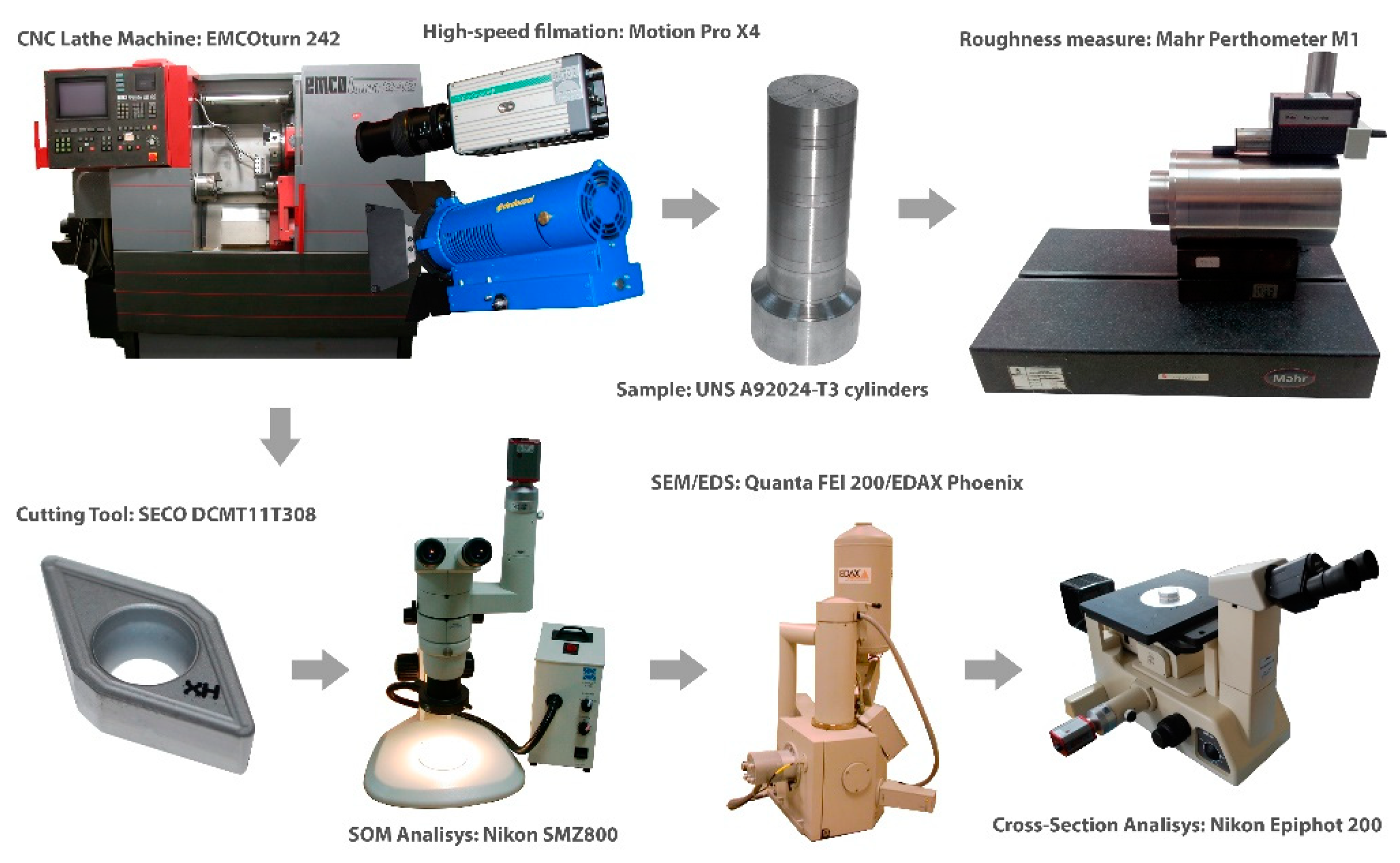
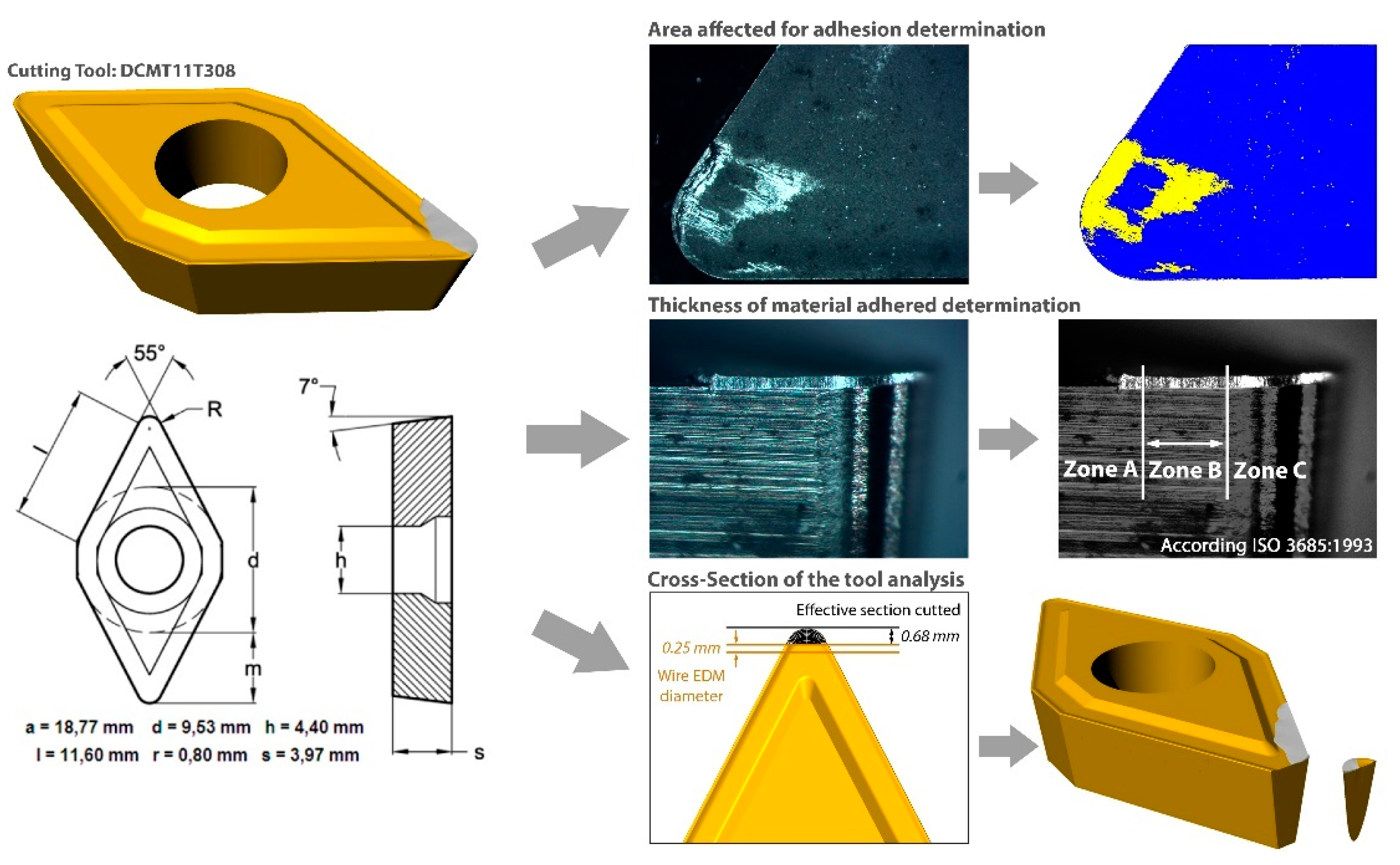
2. Materials and Methods

Dry horizontal turning of UNS A92024-T3 (Al-Cu) aluminum alloy cylinders was carried out with a CNC Lathe EMCOturn 242 (EMCO, Hallein, Austria), with 13 kW power and a EMCOtronic TM02 numerical control. The cutting parameters used in the experiments are shown in Table 1. In order to study the evolution of the tool wear, several tests were performed at different machining times. The cutting speed was set to 100 m/min and with the feed rate at 0.1 mm/rev. These parameters, together with the selected cutting depth, were selected to provide the minimum roughness values from previous works [17,19]. The cutting time, ranging from 0.5 to 120 s, covers a wide range of times, from the firsts instants of machining until wear stabilization. The tool used was an uncoated WC-Co neutral tool with a general-purpose chip-breaker ISO DCMT11T308 [23] from SECO Tools. The main geometrical data are represented in Figure 1. Selection of this cutting geometry comes from its extensive use for machining aluminum alloys [24,25,26]. The experiments were filmed using a Motion Pro X4 (Redlake, Cheshire, CT, UCA) high-speed camera, at a capture frequency up to 8k fps.
The experimental procedure follows the sequence showed in Figure 1.
The rake and the flank face of the tools were observed using a Nikon SMZ800 stereoscopic optical microscope (Nikon, Tokyo, Japan) with a 5 MPx Optikam B5 (Optika, Ponteranica, Italy) digital camera. Tool wear was measured through image filtering and digital measurement with Perfect Image v7 software (Clara Vision, Verrières le Buisson, France). The affected area of the rake face was automatically recognized by filtering the color pattern, taking three measurements for the analysis (Figure 2). Similarly, ten thickness measurements were taken at the flank face, using the ISO 3685 standard as a reference.
Some of the machining conditions were specifically studied by obtaining the cross-section of the tool (Figure 2). The tool was cut using a wire electro discharge machine ONA PRIMA E25 (ONA, Durango, Spain). Then, the sections were slightly ground and studied in a Nikon Epiphot 200 metallographic microscope (Nikon, Tokyo, Japan). Scanning electron microscopy (SEM) and energy dispersive spectroscopy (EDS) were used in order to characterize the section and the entire tool. For this purpose, a FEI QUANTA 200 microscope (ThermoFisher Scientific, Hillsboro, OR, USA) was used with an EDAX Phoenix system (Phoenix, EDAX, Mahwah, NJ, USA). Finally, the surface finish of the part was measured in terms of average roughness values (Ra) with a Mahr Perthometer M1 roughness measure station (Mahr Metrology, Göttingen, Germany).

3. Results and Discussion

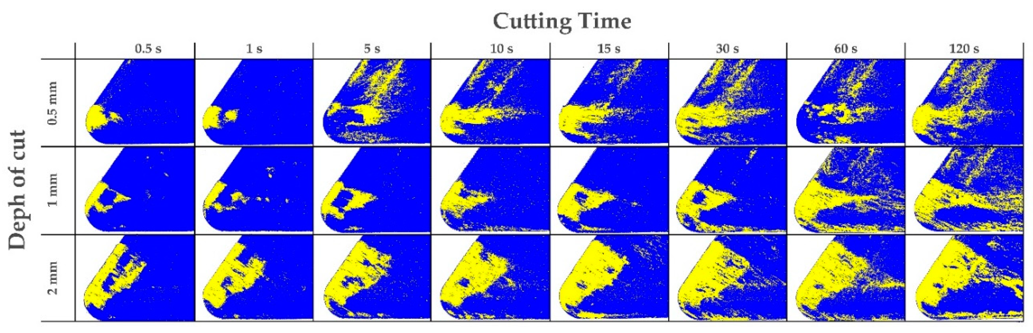
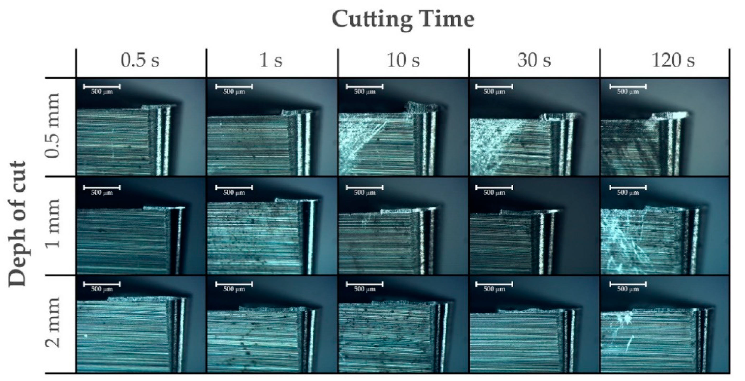
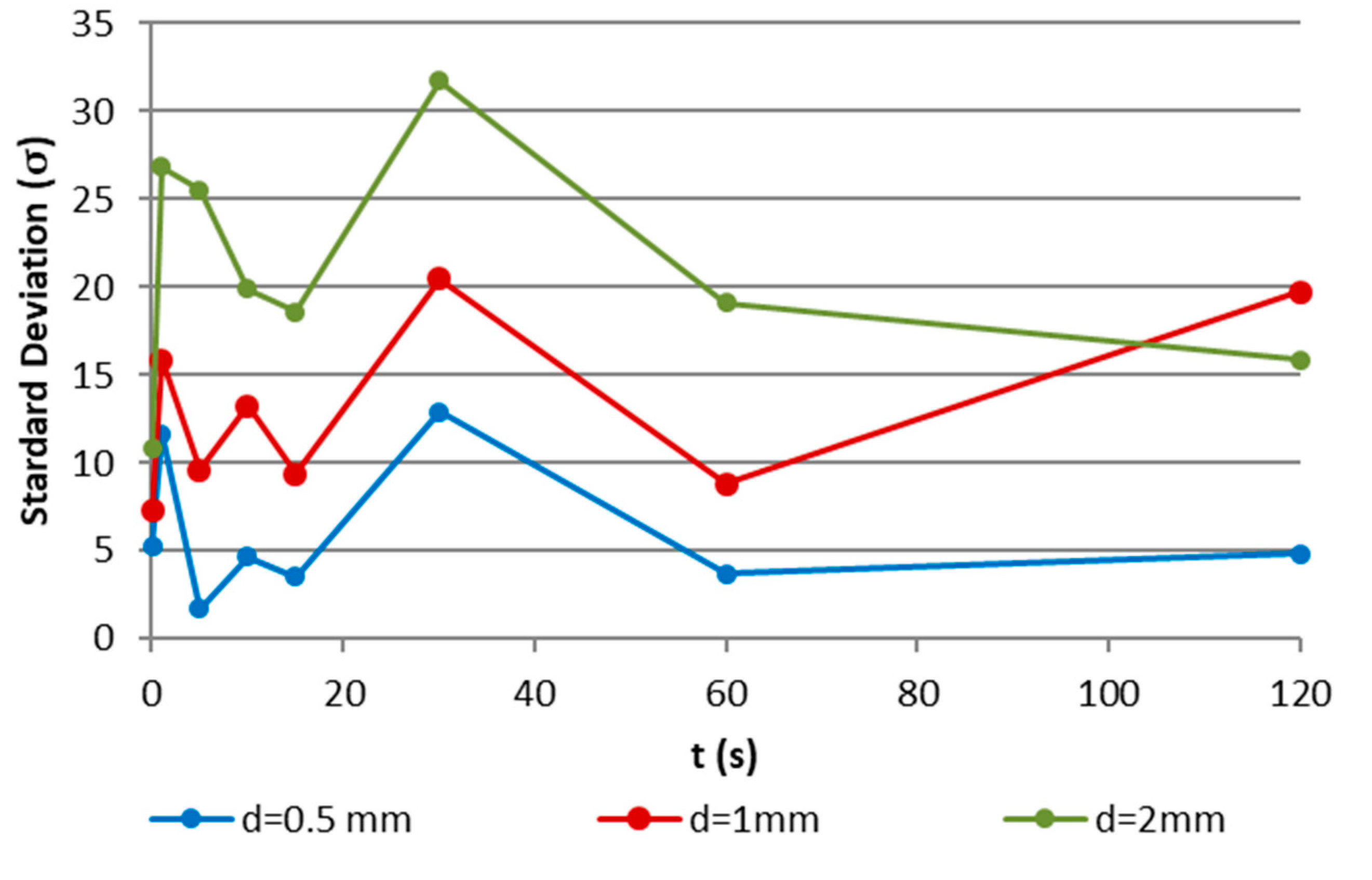
3.1. Evolution of Tool Wear
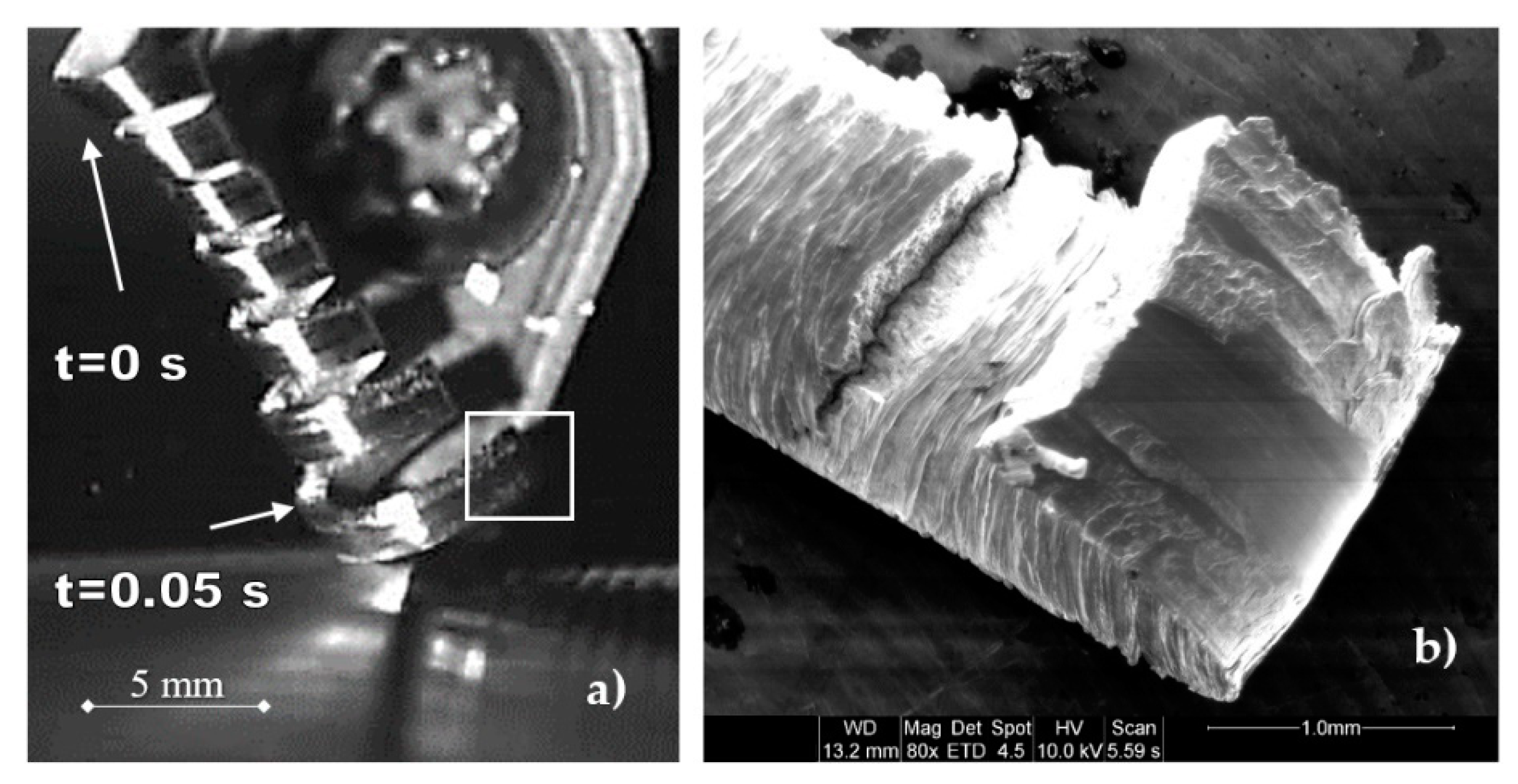
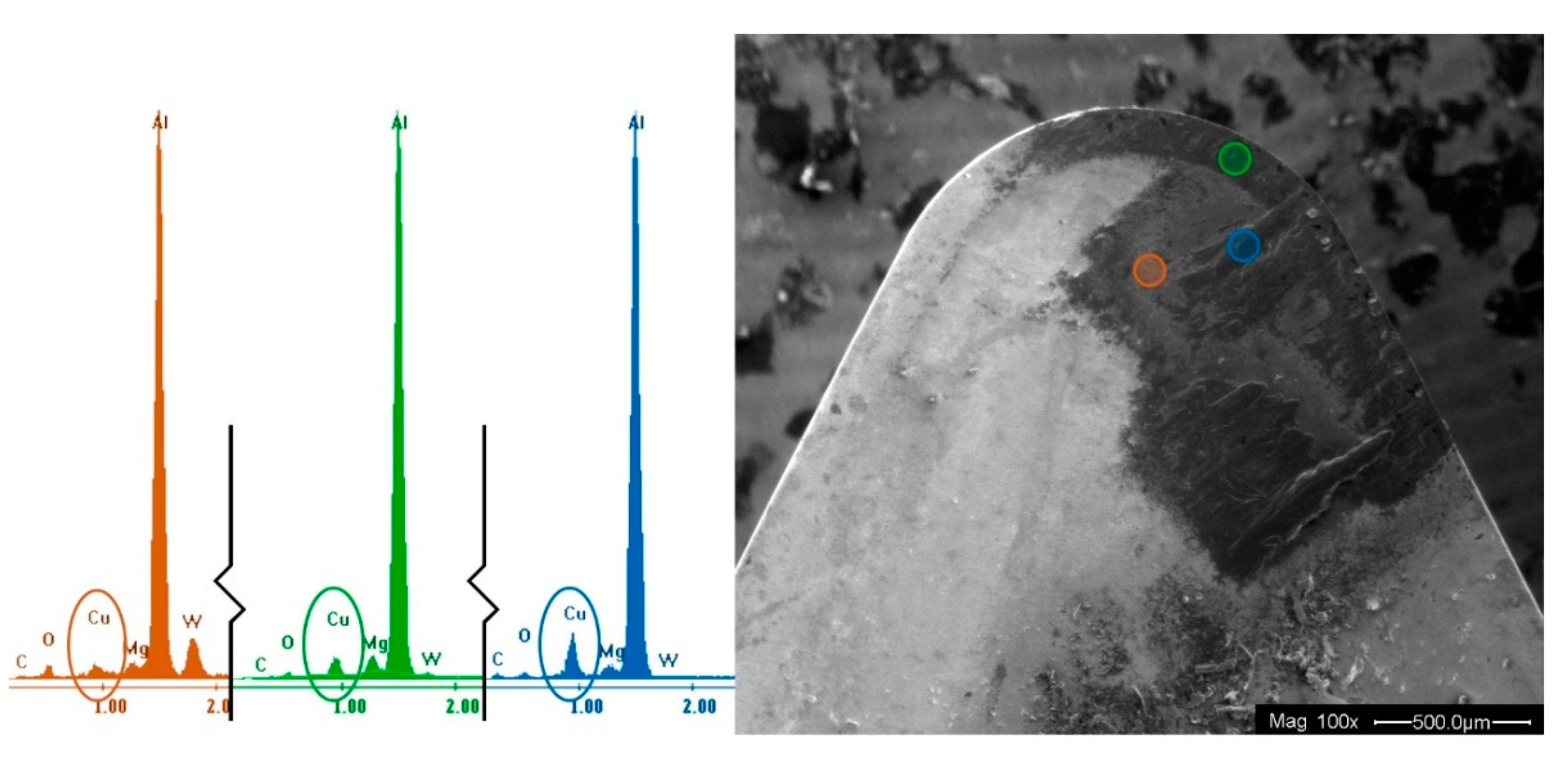
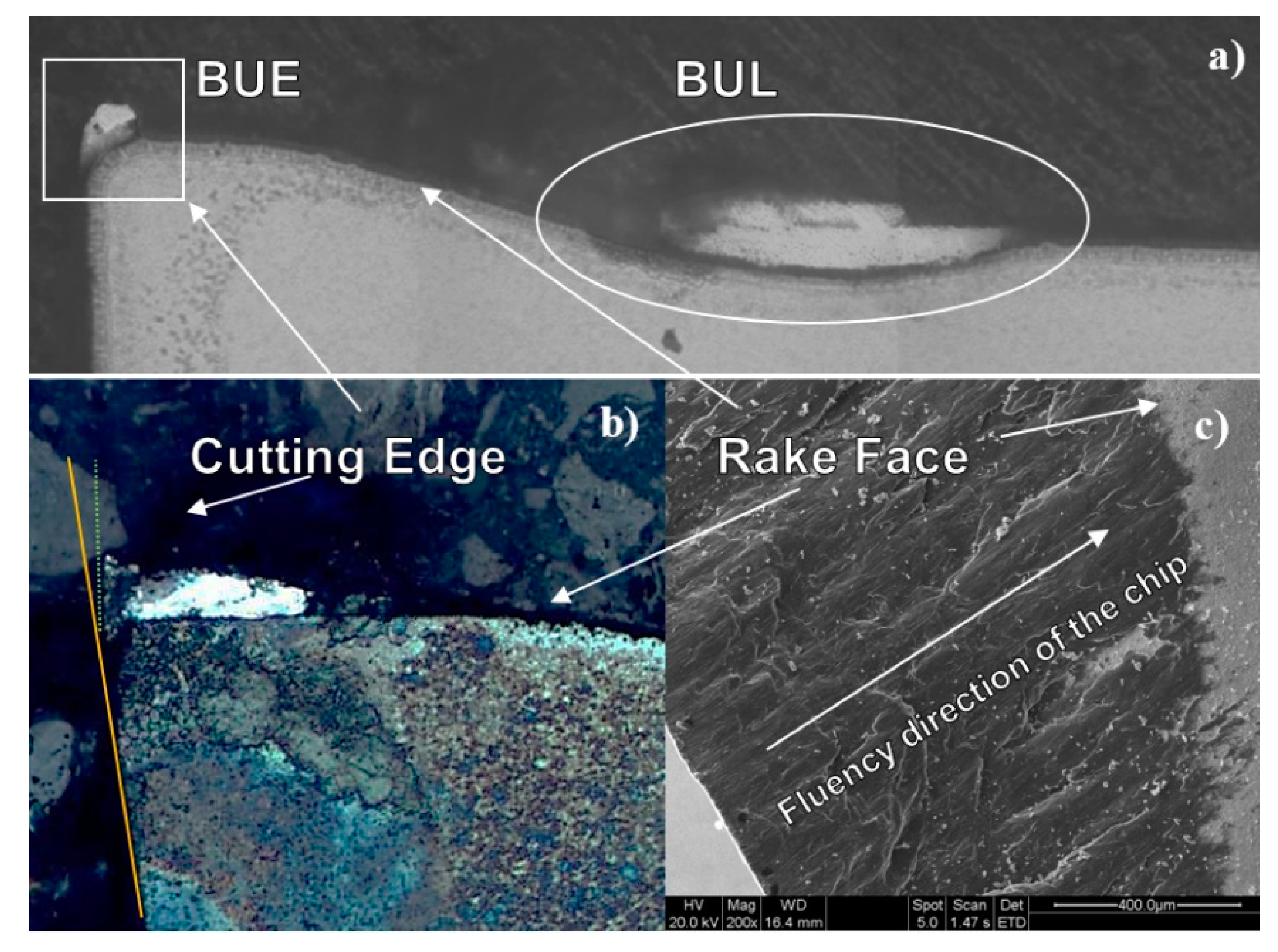
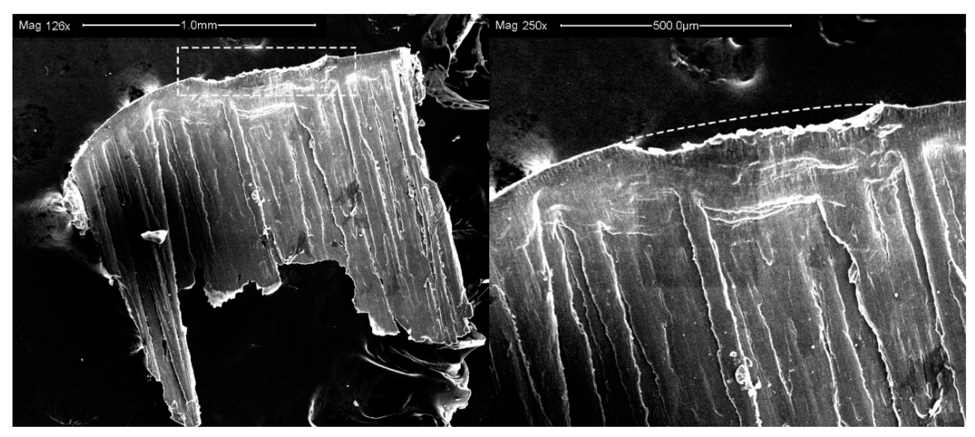
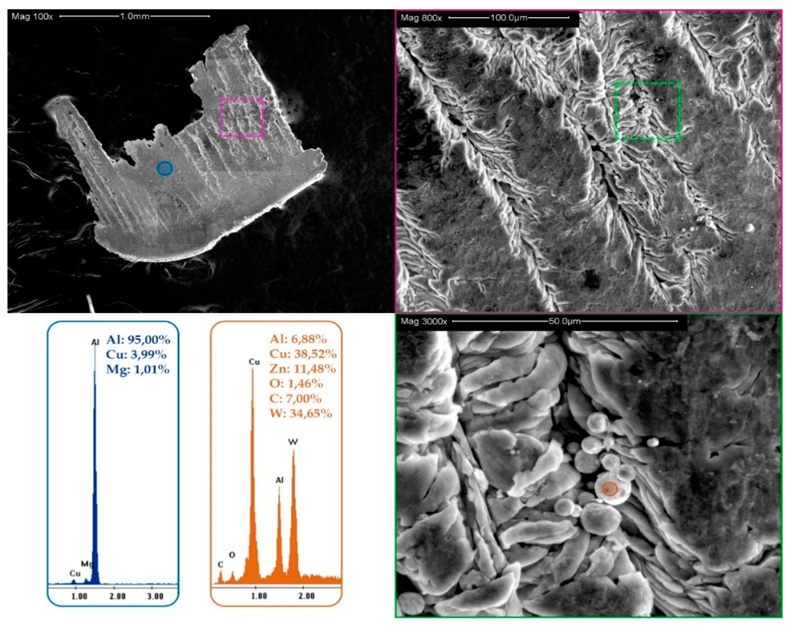
High speed videos were used to analyze the first instants of machining. A change in the chip surface was observed in the first 0.05 s (Figure 3).
Initially, the chip surface was bright and smooth, with no marks or cracks in the contact zone, cutting edge, or rake face, and it did not present any deformation or irregularity. When adhesion started, the surface changed, reducing the contact area and leaving part of the chip without support during its formation, producing cracks and marks on its external surface. For this reason, it is reasonable to think that the development of the adhered material is almost instantaneous, being the more important mechanical component of the wear process, which is in line with other studies [3,6].
Visual inspection analysis for a longer machining time is shown in Figure 4. The width of the affected area is related to the depth of the cut, increasing the contact length between the chip and the rake face. This area generally increases over time, mainly because of the material softening produced by the high process temperatures. In the first instances, and until the BUE was completely extruded over the tool, the temperature increased, softening the aluminum matrix and easing its adhesion to the tool [6]. This fact changes the contact pair to aluminum–aluminum, facilitating the adhesion of the second layer, the BUL [12].
As can be seen in Figure 5, the rake area affected by adhesion tends to increase with cutting time. However, as this process is dynamic, particles of the adhered material are dragged by the chip, temporarily decreasing the affected area. This effect is more significant for the lower cutting depth, where process temperature is lower. An increase in chip rigidity also may affect its extrusion over the tool, a fact that has high relevance in the wear behavior [6,17,19].
Similarly, the thickness of the adhered material increased with cutting time, which behaved in the same way as the area affected by the adhesion (Figure 6). The BUL thickness values fluctuated over a stable value, which means that the volume of the adhered material increased, the same as in previous studies [17].
However, this analysis showed a high variability on the morphology of the material adhered to the cutting edge, which could be related to the changes produced in the force density in the lateral part of the chip fluency. This variability suggested the study of alternative statistical parameters to the average value. For this reason, the standard deviation of the thickness data at each edge was studied, showing a repetitive pattern for the entire cutting depth (Figure 7). This fact proved that the dynamic behavior of the adhesion is more repetitive than expected, and it could be normalized for different cutting depths (d).

3.2. Wear Mechanism

The composition of the adhered layer is affected by the cyclic mechanism. An example of this can be observed in the SEM analysis over the rake face (Figure 8), which revealed three layers with different thicknesses that have slight changes in their composition. The first one, marked in orange in Figure 8, is a thin layer with lower Cu content than the nominal alloy. The second one is thicker, but the amount of Cu in its composition was not as expected from the alloy specifications (4% Cu), indicating that both layers were adhered by thermomechanical processes.
Initially, friction between the tool and chip increases the temperature in the contact area. This smooths the aluminum matrix in this area, almost melting it, and obtaining a thin layer where the interstitial particles are removed by the chip, with only the aluminum matrix being adhered to the upper part of the rake face. This first layer changes the frictional behavior of the contact area, gradually decreasing the cutting temperature, but also improving the transfer between the tool and chip. For this second step, the process is similar, but it is easier to obtain Cu particles at the surface. This thermomechanical adhesion continued up to a thickness where the mechanism changes to mechanical adhesion, caused by the extrusion of the adhered material over the first and second layers.
Finally, the top layer of that adhered material showed the same Cu content as the nominal alloy (4%). This stratification of the adhered material was also previously observed in some studies [3,6,19].
This stratification is given on the rake face following the chip fluency direction (Figure 9c). The cross-section shows how the different layers of material overlap until the chip breaker is filled (Figure 9a). This material looks to be distributed unevenly around the edge of the tool, creating a BUE, and forming a MBUL over the rake face, where it is possible to identify the interface between the layers. In this case, the friction is completely different, being Al–Al instead of Al–WC-Co. This fact could also vary the output of the chip [12].
In addition, the adhered material changed the initial geometrical conditions. Although the rake angle increased (modifying the shear angle and the chip fluency), and consequently changed the wear mechanism to abrasion, the most important change occurred at the edge of the tool. BUE changes the positioning angle of the edge (Figure 9b), directly affecting the surface integrity of the machined part.
According to the literature, mechanically adhered materials are unstable and could detach and drag some parts of the tool [27]. In fact, this emerged in some of the tools studied, which are studied in Figure 5 and Figure 6. When the adhered material is dragged outward, some parts of this material continue to adhere (Figure 10 shows this effect).
As can be observed in Figure 10, there is a fracture in the area close to the cutting edge; there was a non-uniform detachment during machining. On the other side (reverse, Figure 11), there are cracking morphologies in the direction of the chip fluency. These may be produced by the temperature changes during the chip extrusion and the MBUL deposition. The EDS analysis shows the composition close to the aluminum alloy, suggesting that the first layer responsible for the appearance of marks on the chip (primary BUL) does not easily detach. Additionally, the crack on the MBUL surface generally contains small spheres, with W and Cu as the main components. The spheres seem to be part of the intermetallic alloy mixed with tool particles, which could cause synergistic behavior between the two main wear mechanisms: adhesion and abrasion.

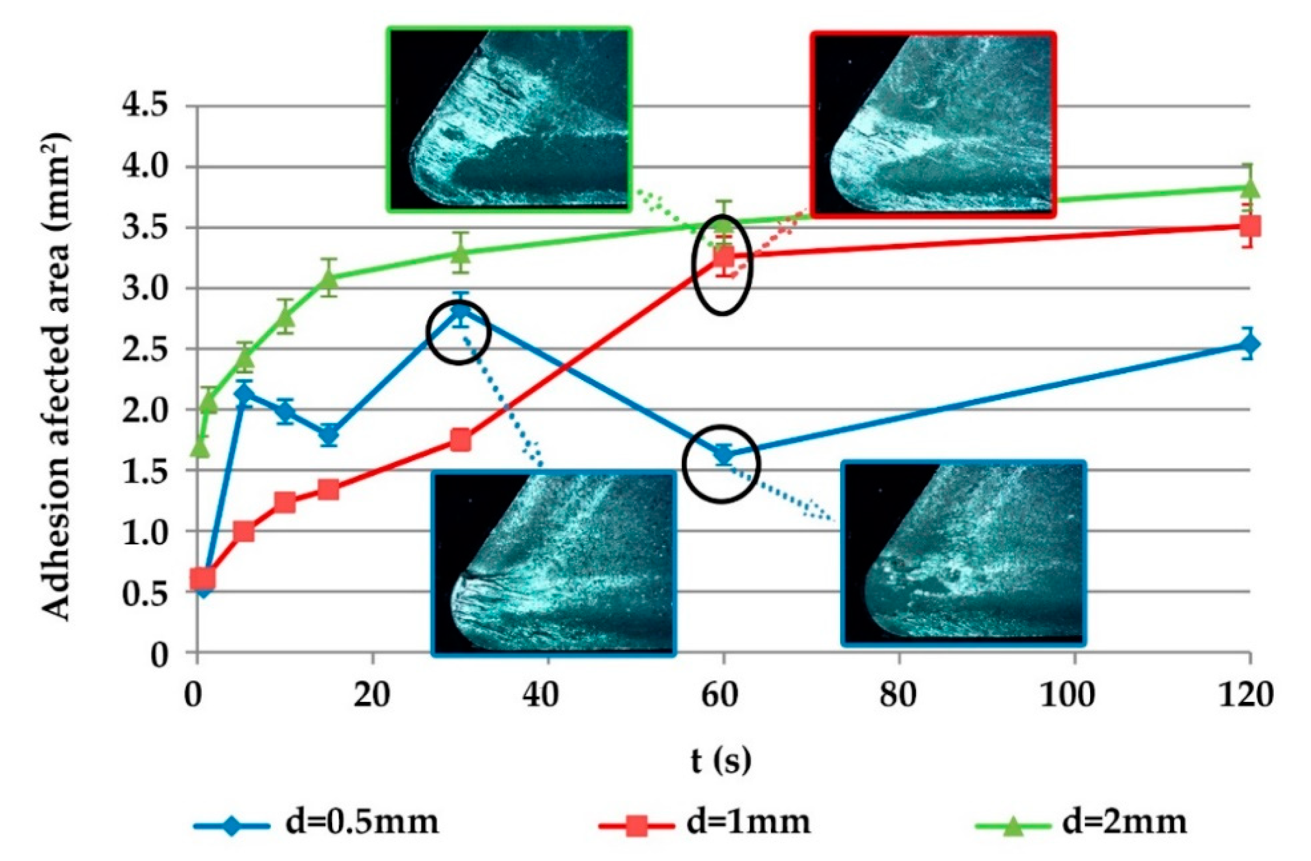
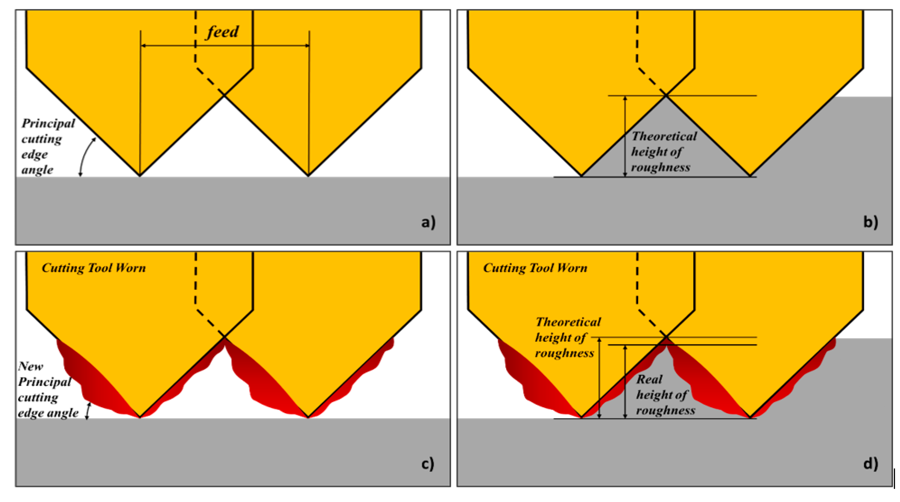
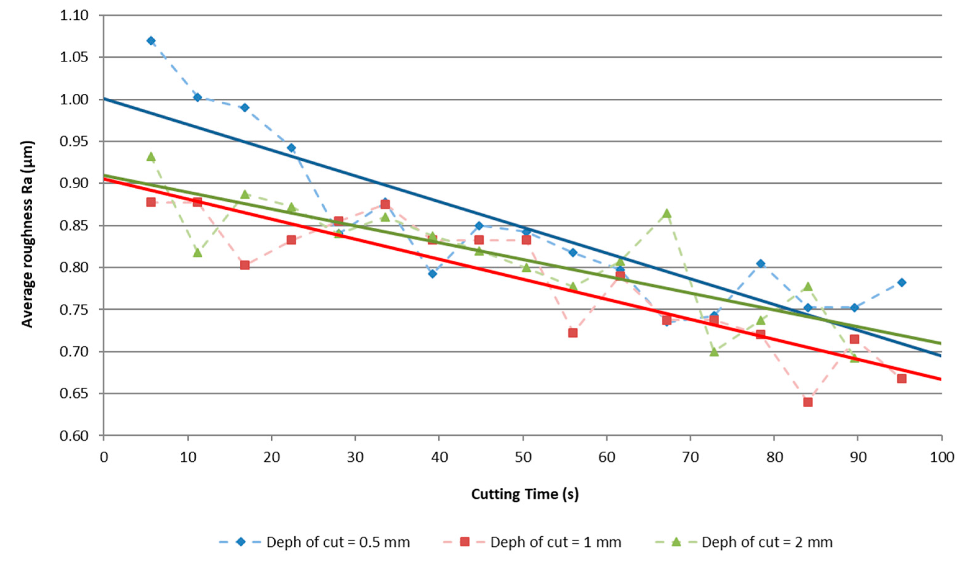
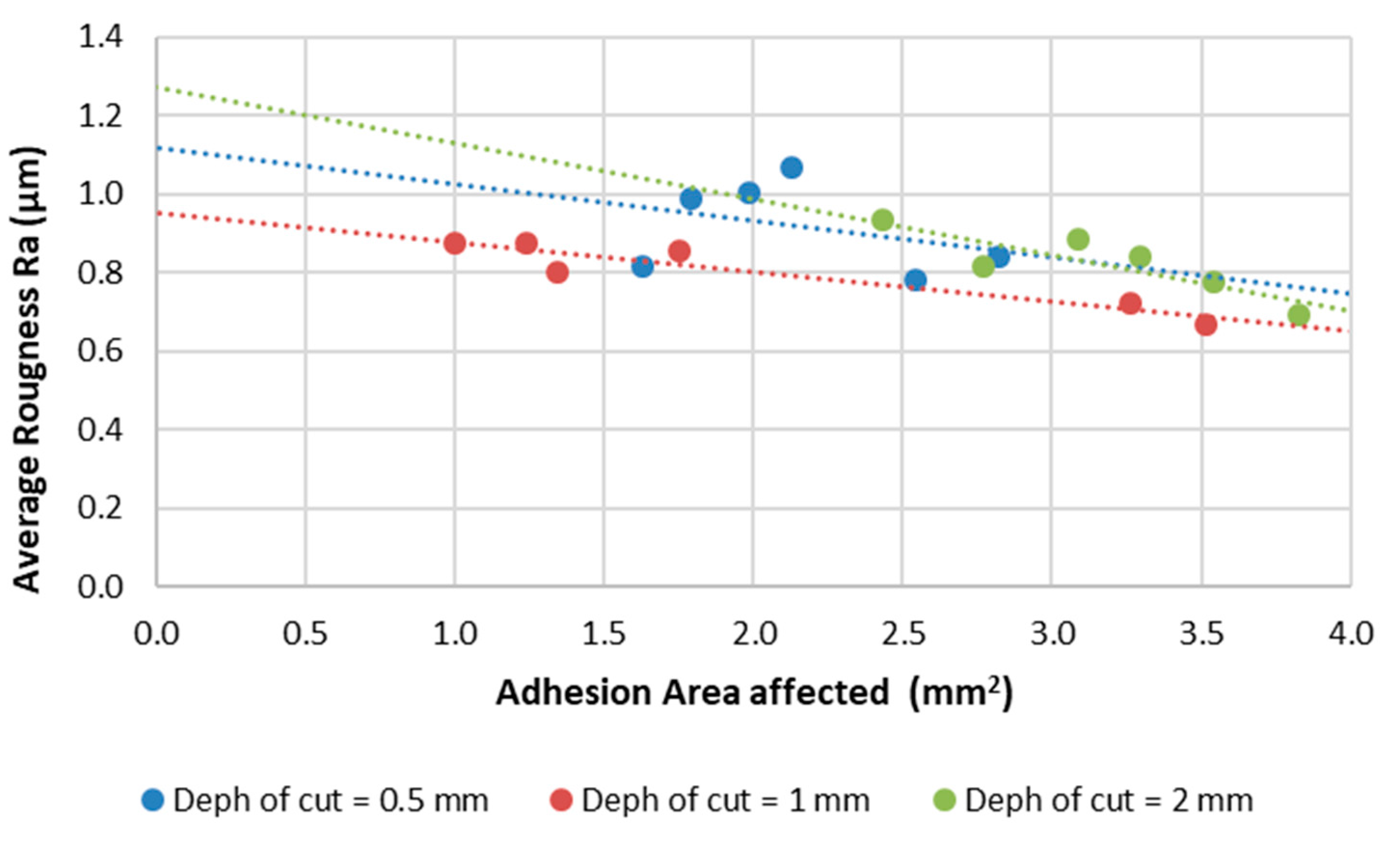
3.3. Relation of Tool Wear and Surface Quality

The instantaneous formation of the adhered material changes the tool geometry and frictional behavior, favoring tool wear. As the secondary adhesion occurred during the machining time (Figure 12c), the main angle position of the cutting edge is modified [3,8,16], leading to a variation of the Ra [11,28,29]. In the case of aluminum alloys, Ra can decrease with the machined length; that is to say, the surface integrity improves as the machining time increases (Figure 13). However, this decrease was accompanied by strong oscillations, caused by the cyclic adhesion and drag process explained above.
Thus, as the adhered material increases, the height of the roughness value decreases, and so Ra decreases. This is shown in Figure 12d, where the real height of the roughness is lower than the theoretical one. Nevertheless, when a part of the adhered material is carried out, as explained above, the height of the roughness increases again, and the Ra suffers a slight increase. This behavior explains the oscillations observed in Figure 13.
The behavior of Ra is highly influenced by the adhered material, but the influence is different depending on the adherence process. If one studies the statistical correlation between Ra and the two secondary adhesion phenomena (BUE and BUL), it is possible to see that the material adhesion in the rake face (BUL) controls the dependence of Ra (Figure 14). The correlation between the thicknesses of materials adhered on the cutting edge is around 40% for a cutting depth of 2 mm, and is worse for the rest of the cutting depths. Therefore, the correlation between the area affected by adhesion and Ra is around 50%, but depending on the depth of the cut, this can be much higher; for a 2 mm depth it is about 86%, and for 1 mm depth it is about 95%.
The above means that when the tool is highly affected by adhesion in the rake face, forming BUL, the Ra decreases via the geometric effect explained before. The general trend is a decrease of the Ra, but this trend is not constant over time, because the tool material that is removed during the cyclical process produces mechanical cracks that weaken the tool, leading to longer times and worse surface quality.

4. Conclusions

This paper studies the wear mechanism of the tool after machining the aluminum–copper alloy UNS A92024 under dry conditions. The main wear mechanism is adhesion, which in some situations presents abrasion phenomena.
Secondary adhesion wear is an instantaneous process. In 0.05 s, a layer of material adhered to the rake face is formed. This layer has very low thickness and low Cu content, caused by the thermo-mechanical process, a fact that changes the tribological behavior of the cutting tool.
This adhered material increases with the cutting time, forming a BUL on the rake face and a BUE over the cutting edge. However, this formation is unstable, as a part of it is dragged with the fluency of the chip.
When the adhered material is dragged out, it removes particles from the cutting tool material in the form of tungsten carbide (WC) spheres. The cyclicity of the process means that the adhered material increases over time and forms a multi-BUL (MBUL), giving rise to a modification in the tool position angle.
The geometrical modification in the cutting tool causes positive changes in the machined parts by decreasing the surface roughness (Ra). In addition, the material adhered to the rake face is the most affected by Ra.
These adhesion effects are independent of depth of cut. When the depth of cut increases, the affected area is higher, but the effect on Ra is similar for all depths of cut.
The best results for surface quality are obtained with 1 mm depth of cut, which could be used in roughing and finishing operations. It is necessary to stabilize the adhesion process by machining for at least one minute.
However, if the adherence process is cyclic and the tool material is removed, the tool is weakened in each cycle.

Author Contributions

M.B. and J.S. conceived and designed the experiments; M.B. and J.S. performed the experiments; M.B., A.G.-P. and M.R.-P. analyzed the data; M.B. and I.D.S. wrote the paper; M.R.-P. and I.D.S. revised the paper.

Funding

This work received financial support from the Spanish Government (Project DPI2015-71448-R) and the University of Cadiz (University training plan UCA/REC01VI/2016).

Acknowledgments

A special acknowledge to Mariano Marcos Bárcena, a great scientist and engineer, who aroused in us the interest in machining research. In memoriam.

Conflicts of Interest

The authors declare no conflict of interest.

References

  1. Wittbecker, G. Aluminium Market Outlook; CRU Group: London, UK, 2018. [Google Scholar]
  2. Santos, M.; Machado, A.; Sales, W.; Barrozo, M.; Ezugwu, E. Machining of aluminum alloys: A review. Int. J. Adv. Manuf. Technol. 2016, 86, 3067–3080. [Google Scholar] [CrossRef]
  3. Gomez-Parra, A.; Alvarez, M.; Salguero, J.; Batista, M.; Marcos, M. Analysis of the evolution of the Built-Up Edge and Built-Up Layer formation mechanisms in the dry turning of aeronautical aluminium alloys. Wear 2013, 302, 1209–1218. [Google Scholar] [CrossRef]
  4. Bar-Hena, M.; Etsionb, I. Experimental study of the effect of coating thickness and substrate roughness on tool wear during turning. Tribol. Int. 2017, 110, 341–347. [Google Scholar] [CrossRef]
  5. Özen, F.; Fıçıcı, F.; Dündar, M.; Çolak, M. Effect of copper addition to aluminium alloys on surface roughness in terms of turning operation. Acta Phys. Pol. 2017, 131, 467–469. [Google Scholar] [CrossRef]
  6. Carrilero, M.S.; Bienvenido, R.; Sánchez, J.M.; Marcos, M. A SEM and EDS insight into the BUL and BUE differences in the turning processes of AA2024 Al–Cu alloy. Int. J. Mach. Tools Manuf. 2002, 42, 215–220. [Google Scholar] [CrossRef]
  7. List, G.; Nouari, M.; Géhin, D.; Gomez, S.; Manaud, J.P.; Le Petitcorps, Y.; Girot, F. Wear behaviour of cemented carbide tools in dry machining of aluminium alloy. Wear 2005, 259, 1177–1189. [Google Scholar] [CrossRef]
  8. Shahabi, H.H.; Ratnam, M.M. In-cycle detection of built-up edge (BUE) from 2-D images of cutting tools using machine vision. Int. J. Adv. Manuf. Technol. 2010, 46, 1179–1189. [Google Scholar] [CrossRef]
  9. Viana, R.; Machado, A. The influence of adhesion between coating and substrate on the performance of coated HSS twist drills. J. Braz. Soc. Mech. Sci. Eng. 2009, 31, 327–332. [Google Scholar] [CrossRef]
  10. Chambers, A. The machinability of light alloy MMCs. Compos. Part A Appl. Sci. Manuf. 1996, 27, 143–147. [Google Scholar] [CrossRef]
  11. Rubio, E.M.; Camacho, A.M.; Sanchez-Sola, J.M.; Marcos, M. Surface roughness of AA7050 alloy turned bars. Analysis of the influence of the length of machining. J. Mater. Process. Technol. 2005, 682–689, 122–123. [Google Scholar] [CrossRef]
  12. Salguero, J.; Vazquez-Martinez, J.; Sol, I.; Batista, M. Application of Pin-On-Disc Techniques for the Study of Tribological Interferences in the Dry Machining of A92024-T3 (Al–Cu) Alloys. Materials 2007, 11, 1236. [Google Scholar] [CrossRef] [PubMed]
  13. Kelly, J.; Cotterell, M. Minimal lubrication machining of aluminium alloys. Mater. Process. Technol. 2002, 120, 327–334. [Google Scholar] [CrossRef]
  14. Vilches, F.T.; Hurtado, L.S.; Fernández, F.M.; Gamboa, C.B. Analysis of the Chip Geometry in Dry Machining of Aeronautical Aluminum Alloys. Appl. Sci. 2017, 7, 132. [Google Scholar] [CrossRef]
  15. Trent, E.M.; Wright, P.K. Metal Cutting, 4th ed.; Elsevier: Amsterdam, The Netherlands, 2000. [Google Scholar]
  16. Atlati, S.; Haddag, B.; Nouari, M.; Moufki, A. Effect of the local friction and contact nature on the Built-Up Edge formation process in machining ductile metals. Tribol. Int. 2015, 90, 217–227. [Google Scholar] [CrossRef]
  17. Batista, M.; Illana, I.D.S.; Fernández-Vidal, S.; Salguero, J. Experimental Parametric Model for Adhesion Wear Measurements in the Dry Turning of an AA2024 Alloy. Materials 2018, 11, 1598. [Google Scholar] [CrossRef]
  18. Coromant, S. Modern Metal Cutting: A Practical Handbook; Sandvik Coromant: Sandwicken, Sweden, 1994. [Google Scholar]
  19. Trujillo, F.; Sevilla, L.; Marcos, M. Experimental parametric model for indirect adhesion wear measurement in the dry turning of UNS A97075 (Al-Zn) alloy. Materials 2017, 10, 152. [Google Scholar] [CrossRef] [PubMed]
  20. Szablewski, E.; Sokolowski, J. High Speed Face Milling of an Aluminium Silicon Alloy Casting. CIRP Ann. 2004, 53, 69–72. [Google Scholar]
  21. Lahres, M.; Müller-Hummel, P.; Doerfel, O. Applicability of different hard coatings in dry milling aluminium alloys. Surf. Coat. Technol. 1997, 91, 116–121. [Google Scholar] [CrossRef]
  22. Roy, P.; Sarangi, S.; Ghosh, A.; Chattopadhyay, A. Machinability study of pure aluminium and Al–12% Si alloys against uncoated and coated carbide inserts. Int. J. Refract. Met. Hard Mater. 2009, 27, 535–544. [Google Scholar] [CrossRef]
  23. International Organization for Standardization. ISO 1832:2012. Indexable Inserts for Cutting Tools—Designation; International Organization for Standardization: Geneva, Switzerland, 2012. [Google Scholar]
  24. Seco Tools Catalog, Seco Tools. 2019. Available online: https://www.secotools.com/article/84585 (accessed on 10 July 2019).
  25. Sandvik Tools Catalog, Sandvik Coromant. 2019. Available online: https://www.sandvik.coromant.com/en-gb/downloads (accessed on 9 July 2019).
  26. Dormer Tools Catalog, Dormer Tools. 2019. Available online: https://www.dormerpramet.com/downloads/pramet%20turning%20chipbreaker%20catalogue%20en.pdf (accessed on 15 July 2019).
  27. Komanduri, R. Machining and grinding: A historical review of the classical papers. Appl. Mech. Rev. 1993, 46, 80–132. [Google Scholar] [CrossRef]
  28. Salguero, J.; Batista, M.; Garcia-Jurado, D.; Gamez, A.J.; Marcos, M. Evolution of the Surface Quality in the High Speed Milling of Aerospace Aluminum Alloys. Adv. Sci. Lett. 2013, 19, 379–383. [Google Scholar] [CrossRef]
  29. Sánchez-Sola, J.M. Parametric Analysis of Machining Aluminum Alloys. Relation to the Topography of the Machined Samples. Ph.D. Thesis, Universidad Nacional de Educación a Distancia (UNED), Madrid, Spain, 2004. [Google Scholar]
Figure 1. Experimental procedure and equipment. Abbreviations: SEM = scanning electron microscopy; EDS = energy dispersive spectroscopy; SOM = stereoscopic optical microscopy.
Metals 09 01094 g001
Figure 2. Experimental proposal for adhesion evaluation.
Metals 09 01094 g002
Figure 3. (a) High speed filming frame, where the chip formation in the beginning of the machining can be observed. (b) SEM image from the chip surface.
Metals 09 01094 g003
Figure 4. Secondary adhesion wear evolution in the zenith plane, evaluated with phase contrast analysis.
Metals 09 01094 g004
Figure 5. Secondary adhesion affected area as a function of cutting time.
Metals 09 01094 g005
Figure 6. Evolution of the adhered material over the rake face from a vertical plane projected on the clearance face.
Metals 09 01094 g006
Figure 7. Standard deviation evolution of the thickness of the adhesion as a function of cutting time.
Metals 09 01094 g007
Figure 8. SEM and EDS analyses of the tool after 10 s machining at Vc = 100 m/min, f = 0.1 mm/rev, d = 1 mm.
Metals 09 01094 g008
Figure 9. (a) Cross-section of the tool. (b) Overlapped layers of adhered material. (c) SEM of stratified structure of adhered material.
Metals 09 01094 g009
Figure 10. Scanning electron microscopy of the detached adhered material.
Metals 09 01094 g010
Figure 11. Analysis of the reverse face of the adhered material.
Metals 09 01094 g011
Figure 12. Tool wear effect on the surface roughness. (a) Initial cutting scheme. (b) Theoretical height of roughness during the machining process. (c) Cutting scheme with adhesion wear effects. (d) Reduction on roughness due to adhesion in flank face.
Metals 09 01094 g012
Figure 13. Ra evolution as a function of machining time (Vc = 100 m/min; f = 0.1 mm/rev). Solid lines represent linear trends.
Metals 09 01094 g013
Figure 14. Evolution of Ra as a function of the area affected by adhesion, for each depth of cut. Dotted lines represent linear trends.
Metals 09 01094 g014
Table 1. Cutting parameters.
Cutting Speed (Vc) [m/min]100
Feed (f) [mm/rev]0.10
Depth of cut (d) [mm]0.51.02.0
Cutting time (t) [s]0.5–1–5–10–15–30–60–120

