Article

Effect of the Number of CFRP Prepregs and Roughness at the Bonding Area on the Spring-Back and Flexural Strength of Hybrid Composites of CFRP Combined with CR980

1
Precision Manufacturing System Division, Graduate School, Pusan National University, San 30 Chang Jun-dong, Geum Jung-Gu, Busan 46241, Korea
2
School of Mechanical Engineering, Kyungnam University, 7 Kyungnamdaehak-ro, Masanhappo-gu, Changwon-si, Gyeongsangnam-do 51767, Korea
3
Department of Computer Software Engineering, ChangShin University, 262 Paryong-ro, Masanhoiwon-gu, Changwon-si, Gyeongsangnam-do 51352, Korea
4
School of Mechanical Engineering, Pusan National University, San 30 Chang Jun-dong, Geum Jung-Gu, Busan 46241, Korea
*
Author to whom correspondence should be addressed.
Metals 2019, 9(10), 1054; https://doi.org/10.3390/met9101054
Submission received: 5 August 2019 / Revised: 24 September 2019 / Accepted: 26 September 2019 / Published: 28 September 2019

Abstract

:
Hybrid composites in which a CR980 metal plate was bonded on carbon-fiber-reinforced plastic (CFRP) were prepared. Hybrid composites were two types of CFRP/CR980 hybrid composites and CR980/CFRP hybrid composites. The properties of the hybrid composites according to surface roughness on CR980 plate and the laminating number of CFRP prepregs were analyzed. The spring-back or spring-go angles were also measured through the V-bending test of hybrid composites. In addition, a three-point bending test for the hybrid composites was conducted to measure the flexural strength. Spring-back occurred in the CFRP/CR980 hybrid composites, while spring-go was observed in the CR980/CFRP hybrid composites. Voids were not found at the bonding area of the CFRP and CR980. As the roughness at the bonding area increased, the flexural strength slightly increased. The higher the laminating number of the CFRP prepregs, the lower the deformation value. CFRP/CR980 was deformed more easily than CR980/CFRP.

1. Introduction

Additional components for vehicles, especially in the case eco-friendly automobiles fueled by a non-conventional power source, have led to unavoidable increases in curb weight. This increase is expected to be on the order of 10% each for non-ferrous metal and synthetic resin applied to eco-friendly cars. Increasing car weights have recently required more convenient and safer cars (i.e., body-reinforcing materials, airbags, motors, and storage batteries), and the resulting practical mission is to resolve the heavy car components’ weight to produce lighter automobiles [1,2].
In response to the demand for lighter components, the use of metal alloys of aluminum, magnesium, titanium, advanced high strength steel (AHSS), as well as composite materials, has been increasingly popular in the car industry. One composite material, carbon-fiber-reinforced plastic (CFRP), possesses a specific strength and specific stiffness that are higher than steel, in addition to being lighter than aluminum. Thus, fundamental studies on its application for car body and chassis components are being advanced [3,4,5].
CFRP’s applications are being expanded to various other fields, such as aircrafts and recreational infrastructure; nevertheless, its high tensile strength is compensated by weakness against shock owing to its low elongation rate (approximately 2%). Therefore, research focusing on creating hybrid composites to overcome the limits of CFRP and resolve the problem of homogeneous materials by bonding it with certain metals have been advanced. Moreover, the phenomenon of spring-back on CFRP/metal hybrid composites considering changes in thickness of CFRP prepreg has not been extensively studied. In this regard, spring-back investigations via experiments are imperative before manufacture of the hybrid-composite-based components forming complex geometry (e.g., automobile components). The interface strength bonding between metals and CFRP is critical for the hybrid composites [6,7,8,9,10,11,12].
A previous study investigated bonding strength and spring-back according to CR980 surface roughness, CR980 rolling direction, and laminating pressure [13]. In this study, two types of hybrid composites comprising CFRP combined with CR980 metal sheet were fabricated. The first type was a CFRP/CR980 hybrid composite and the second type was a CR980/CFRP hybrid composite. CR980 is an ultra-high-strength steel used as a pillar component and support for the bottom of vehicle bodies, and thus plays an essential role in the safety and protection of passengers by absorbing shock during collisions. To improve the bonding strength of these heterogeneous materials, physical surface treatment on surface CR980 was carried out using the sandblast method. The effect of the laminating number of the CFRP prepreg and the interface roughness between CFRP and CR980 on the spring-back was investigated by performing a V-bending test of both types of hybrid composite. Magnified images of the cross-cut section of the V-bending specimens were measured. Furthermore, the effect of the laminating number of CFRP prepregs and interface roughness between CFRP and CR980 on flexural stress was investigated by conducting a three-point bending test of the hybrid composites.

2. Experiment Methods

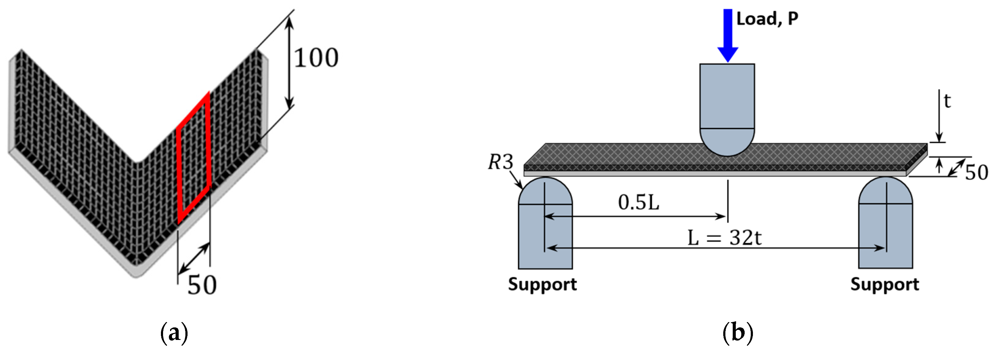
2.1. V-Bending Test of Hybrid Composites

The CFRP used was a plain woven prepreg from TORAY; the prepreg was a 0.27-mm thick, thermosetting epoxy carbon fiber with initial epoxy weight percent of 42 wt% [14]. Prepreg is a material in which matrix epoxy resin is impregnated in the carbon fiber, which is an intermediate material of CFRP as well as a reinforcement material. The properties of the CFRP prepreg are listed in Table 1. The metal plate used in this study was CR980, which exhibits excellent strength and safety, and therefore can be manufactured into complex-shaped products. The CR980 used in the experiment had a thickness of 1.2 mm, tensile strength of 1043 MPa, and elongation rate of 18% [15].
Figure 1 shows the shape and dimension of the die used in the V-bending test. It was roughly divided into the top die and bottom die, and had a hole drilled for insertion of a heat cartridge that controls the temperature of the top and the bottom dies. The curvature diameters of the top and bottom dies were R = 5 mm. A 25 ton material testing system (MTS) was used for the V-bending test.
A binder (ATG-2014) was spread on the CR980 surface to fabricate hybrid composites of CFRP combined with CR980. The curing time was set to 140–150 °C for 15 min under 1 MPa pressure. This condition was obtained relative to the optimized curing time for the CFRP and metal hybrid composite [17]. Kinds of hybrid composites in this study for fabrication are shown in Table 2. Thirty different kinds of hybrid composites were fabricated. To investigate effect of the number of CFRP prepregs on spring-back and flexural stress of the hybrid composites were prepared by laminating the CFRP prepreg with 5, 10, and 15 plies, respectively.
To investigate effect of roughness at the bonding area between CFRP and CR980 on spring-back and flexural stress, the physical surface treatment on the CR980 surface was carried out using the sandblast method. The pressure (compressed air) used usually determines the surface roughness of CR980. The degree of surface roughness was measured by ten-point average roughness. The ten-point average roughness was determined with Equation (1). The sum of these two values is expressed in micrometers. As the surface roughness of the CR980 increased, the bonding strength of the CFRP/metal hybrid composite increased [17,18]. The surface roughness values of the CR980 without surface treatment were about 4–8 µm.
Ten point   average   roughness = 1 5 ( | p 1 + p 2 + p 3 + p 4 + p 5 | + | v 1 + v 2 + v 3 + v 4 + v 5 | )
Here, p1p5 and v1v5 are the heights of the five highest profile peaks and the depths of the five deepest valleys within the evaluation length, respectively.
To investigate the effect of bonding sequence on spring-back and flexural stress, the hybrid composites were prepared as CFRP/CR980 and CR980/CFRP. The specimens were named from the material types and as per the boning sequence when the specimens were placed on the die (i.e., the CFRP combined on the CR980 was defined as CFRP/CR980, and the CR980 combined on the CFRP was marked as CR980/CFRP).
The prepared hybrid composite was evaluated with a V-bending test while the spring-back or spring-go angles were measured using a digital protractor from BLUEBIRD. Five samples of the prepared hybrid composite were cut to measure the composite’s thickness. The cross-sectional thickness was measured by a digital microscope. V-shaped curved sections were cut to observe voids of the hybrid composites. The cut surface was polished and then observed by digital microscope. The ASTM D4762 standard for the overall test method for CFRP was also referred to [19,20].

2.2. Three-Point Bending Test of Hybrid Composites

The three-point bending test was carried out after the V-bending test for the specimens with bonded CR980 and CFRP prepregs. Figure 2a shows points from where three-point bending test specimens were taken. The specimen length and width were respectively set to 100 and 50 mm. The thickness of the specimen differed according to the laminating number of the CFRP prepregs. Figure 2b shows the three-point bending test method using the prepared specimen. Figure 2 shows an example of the experimental method, and the same experiment was carried out for the CR980/CFRP under the same testing condition. In the three-point bending test for the composite materials, a ratio between the length of both the support points of the specimens and the thickness of specimen of 32:1 is recommended [21]. Since the thicknesses of specimens differed according to the laminating number of the CFRP prepregs, the support point length was adjusted according to the specimen thickness. The load point was set at the center between two supports. The reaction force at the support point became half of the load, which is 0.5 P. The experiment was carried out by placing the specimen on the two supports. The center of specimen was pressed with the nose as load, and the nose moved down with the same speed until the specimen fractured. The load value of the specimen was measured according to the distance traveled by the load nose. From this experiment, the flexural strength value was obtained. The flexural strength refers to a stress value at the outer side of the specimen from where the maximum bending moment is generated.
At the load point, a maximum bending moment (0.25 PL) is generated. In addition, the maximum flexural strength value is obtained from the outer side of specimen at the load point. In case of the CFRP/CR980 specimen, the maximum minus flexural strength value was generated at the outer surface of the CFRP, while the maximum plus flexural strength value was obtained from the outer surface of the CR980.
Equation (2) shows a calculation formula to determine minus maximum flexural strength at the outer side of the CFRP, while Equation (3) is a formula to draw the plus maximum flexural strength at the outer side of the CR980:
σ 1 max = E 1 M E 1 I 1 + E 2 I 2 C 1 ,
σ 2 max = E 2 M E 1 I 1 + E 2 I 2 C 2 ,
where E1 and E2 are the Young’s modulus of CFRP and CR980, respectively, I1 and I2 are the second moments of inertia of the CFRP and CR980, M is the maximum bending moment, C1 is the distance from the centroid to the outer surface of the CFRP, and C2 is the distance from the centroid to the outer surface of CR980.
The flexural strength at the bonding area of the CFRP and CR980 could be calculated as follows: by entering the distance from the centroid to the bonding point in place with C1 in Equation (2), the flexural strength from the CFRP value was obtained. Meanwhile, the flexural strength from the CR980 could be determined by entering the distance from the centroid to the bonding area in place with C2 in Equation (3). The centroid of the hybrid composites was determined with Equation (4):
C = E 1 A 1 Y d A + E 2 A 2 Y d A E 1 A 1 + E 2 A 2 ,
where A1 and A2 are the cross-sectional areas of CFRP and CR980, while A 1 Y d A and A 2 Y d A are the first moments of inertia of CFRP and CR980. Each item in the above equation becomes the reverse of CFRP/CR980 for the CR980/CFRP specimen.

3. Experimental Results

3.1. Angle of Spring-Back or Spring-Go from the V-Bending Test of Hybrid Composites

Figure 3a shows the formed CFRP/CR980 hybrid composites forming a V-shape through the V-bending test. Meanwhile, Figure 3b shows deformed CR980/CFRP hybrid composites forming a V-shape. The spring-back for CFRP/CR980 hybrid composites and spring-go for CR980/CFRP hybrid composites were observed. Spring-back occurred when the top die made contact with the CFRP prepreg, while spring-go occurred when it made contact with the CR980. These took place because of the difference of mechanical properties between the CFRP prepreg and the CR980. In general, as the laminating number of CFRP prepregs increased, the spring-back angle was close to 90°, as CFRP thickness, as well as the effect of its epoxy matrix, also increased.
The spring-back angles of the CFRP/CR980 hybrid composites according to roughness at the bonding area and the laminating number of the CFRP prepregs are shown in Figure 4a. When the laminating number of the CFRP prepregs increased from 5 to 10, the spring-back increased, but when the laminating number of the CFRP prepregs increased further from 10 to 15, the spring-back decreased. When the laminating number of CFRP prepregs was 5, the spring-back angle increased as roughness increased to 45 µm. However, with 60 µm roughness, the spring-back angles were decreased to 96.4°. When the laminating number of CFRP prepregs was 10, as roughness increased from no treatment to 60 µm, the spring-back angle increased. When the laminating number of CFRP prepregs was 15, as roughness increased from no treatment to 60 µm, the spring-back angle also increased.
As shown in Figure 4a, the spring-back angle increased when the laminating number of CFRP prepregs was more than 10 and as roughness increased. In the CFRP/CR980, the elasticity of the CFRP considerably affected spring-back more than CR980 as the top die came into contact with the CFRP during compression while the load was removed.
The spring-go angles of the CR980/CFRP hybrid composites according to roughness at the bonding area and the laminating number of CFRP prepregs are shown in Figure 4b. When the laminating number of the CFRP prepregs increased from 5 to 15, the spring-go showed a decreasing tendency. In Figure 4b, the spring-go angle increased as roughness increased from no treatment to 60 µm, and when the laminating number of CFRP prepregs was 5, the spring-go angle increased. When the laminating number of CFRP prepregs was 10, as roughness increased from to 20 to 60 µm, the spring-go angle increased. In the case of no treatment, spring-back occurred. When the laminating number of CFRP prepregs was 15 and roughness increased from 20 to 60 µm, the spring-go angle generally decreased as follows: 87.9°, 88.9°, 89.1°, 90°. In the case of no treatment, spring-back occurred. When the roughness was 60 µm, spring-go did not occur, which was the same as the initial angle of the die. When the laminating number of CFRP prepregs was 15 (and not 5 or 10), the spring-go angles decreased as roughness at the bonding area increased.
Figure 5 shows the thickness according to the laminating number of the CFRP prepregs in the CFRP/CR980 hybrid composite. The thickness range was 1.83–1.98 mm when the laminating number of CFRP prepregs was 5. The thickness range was 2.85–3.11 mm when the laminating number of CFRP prepregs was 10 [13]. The thickness range was 3.71–3.81 mm when the laminating number of CFRP prepregs was 15. In general, a thickness range of 2–3 mm for the material is suitable for the body pillar and bottom frame components of automobiles. To meet these conditions, a 1.2-mm-thick CR980 and ten CFRP prepregs should be used. Increasing the laminating number of CFRP prepregs resulted in a thicker CFRP/CR980 hybrid composite at the side than the center, which could be attributed to a concentration of pressure at the center compared to at the side of the top and bottom dies.
Figure 6 shows images of the cross-cut section of the V-bending CFRP/CR980 hybrid composites to examine the presence of pores according to the changes in the surface roughness of CR980. The positions in the cross-sectional images indicate where bending deformation was maximal. The figure does not show pores at the interfacial bonding area; therefore, the preparation condition of the proposed CFRP/CR980 hybrid composite was reasonable.

3.2. Flexural Strength from the Three-point Bending Test of Hybrid Composites

The flexural stresses according to the roughness at the bonding area of the CFRP/CR980 and CR980/CFRP hybrid composites wherein ten CFRP prepregs were laminated are presented in Figure 7. When the loading nose came into contact with the surface of the specimen, some flexural stress values increased because the surface started to deform. From the displacement of 0.35 mm, the specimens began to show elastic deformation, and flexural stress increased linearly in response to the displacement. As soon as yielding occurred, fracture of the CFRP occurred. Figure 7a shows the flexural stress according to the displacement of the CFRP/CR980 hybrid composites having different types of roughness at their bonding interfaces. As can be seen in Figure 5, the thickness of the CFRP/CR980 hybrid composites with ten CFRP prepregs was around 2.9 mm. The location of the centroid calculated from Equation (4) was distanced 1.41 mm from the bottom surface of the CR980. Therefore, the CFRP received compressive stress from the centroid to the top surface, while it received tensile stress from its centroid to the bonding area. However, the CR980 received only tensile stress. At the bonding area, a stress equivalent to 85% of the stress was generated at the portion with maximum stress.
When the nose made contact with the CFRP, the flexural stress abruptly increased as the displacement increased, and then it decreased due to separation of the fiber and the epoxy of the CFRP prepreg under compression. Flexural stress became constant from the displacement of 1.5 to 2.0 mm. As the roughness value at the bonding area of the CFRP/CR980 increased, the flexural stress became slightly increased. The absolute value of the maximum compressive stress generated from the top surface of the CFRP became almost similar at a level of 95% of the maximum tensile stress from the bottom surface of the CR980.
Figure 7b presents the flexural stress according to the displacement of the CR980/CFRP hybrid composites with different types of roughness at their bonding area. The location of the centroid calculated from Equation (4) had a distance of 1.49 mm from the bottom surface of the CFRP. Therefore, the CFRP received a tensile stress from its centroid to the bottom surface, while a compressive stress was imposed on the portion from the centroid to the bonding area. Meanwhile, the CR980 received only a compressive stress. The carbon fiber might have fractured at the position where flexural stress abruptly decreased as the displacement increased. The specimens without surface treatment fractured at displacement values of 1.5 mm. This means that when the roughness at the boding area of CR980/CFRP hybrid composites increased, the displacement value also increased.
As surface roughness on the CR980 increased, the flexural stress increased and reached a maximum at 45 µm. At 60 µm, the flexural stress decreased more than at 45 µm. Therefore, the flexural stress was presumed to affect the surface roughness of the metal. In the CFRP/CR980 hybrid composites, except for the specimens not receiving surface treatment, they were not fractured even with the displacement value of 2.0 mm. However, CR980/CFRP hybrid composites fractured with the displacement value of about 1.5 mm. The above results suggest that the hybrid composites with CR980 bonded on the CFRP were more prone to deformation when CFRP received a compressive stress rather than a tensile stress.
The flexural stresses of CFRP/CR980 and CR980/CFRP hybrid composites having the roughness of 20 µm at the bonding area according to the lamination number of CFRP prepregs are presented in Figure 8. When five CFRP prepregs were laminated, the CFRP of the CFRP/CR980 hybrid composites received only a compressive stress, while the CFRP of CR980/CFRP hybrid composites received only a tensile stress. The specimens having the laminating numbers of CFRP prepregs 10 and 15 received both tensile and compressive stress on their CFRPs.
Figure 8a presents the flexural stress according to the displacement of CFRP/CR980 hybrid composites having different laminating number of CFRP prepregs. The flexural strength decreased as CFRP prepreg thickness increased. When the CFRP prepreg received pressure, the flexural stress became constant even if the displacement increased, which corresponded to the maximum flexural stress owing to the interfacial separation between the fiber and the matrix. However, when the laminating number of CFRP prepregs was 15, the flexural stress remarkably decreased as the displacement increased from the maximum flexural stress, because the greater number of CFRP prepregs caused more damage to the fiber during the three-point bending test.
Figure 8b shows the flexural stress of the CR980/CFRP hybrid composites having different lamination numbers of CFRP prepregs according to the displacement. When the CFRP prepreg received the tensile stress, the fiber was fractured, and thus the flexural stress decreased from the displacement corresponding to the maximum flexural stress.
The flexural stress decreased for both the CFRP/CR980 hybrid composites and CR980/CFRP hybrid composites as the laminating number of CFRP prepregs increased, and those fractured at the even lower displacement values. This is because as the thickness of the CFRP increased, CFRP was not easily deformed, and consequently, the fracture toughness value decreased. This indicates that specimens were easily fractured as the thickness of the CFRP increased.

4. Conclusions

V-bending test and three-point bending test were conducted to investigate the effect of the roughness at the bonding area and laminating number of the CFRP prepregs on CFRP/CR980 hybrid composites and CR980/CFRP hybrid composites; the conclusions below are drawn.
(1)
Spring-back was observed for CFRP/CR980 hybrid composites, and spring-go was observed for CR980/CFRP hybrid composites.
(2)
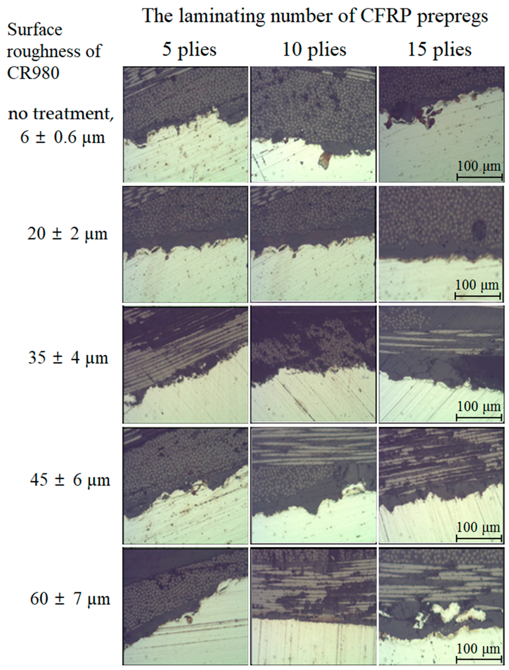
There were no pores at the interfacial bonding area of V-curved surface through V-bending test.
(3)
As the roughness value at the bonding area of the CFRP/CR980 increased, the flexural stress became slightly increased.
(4)
CFRP/CR980 hybrid composites were more prone to deformation when CFRP received a compressive stress rather than a tensile stress.
(5)
The flexural strength and deformation values decreased for both the CFRP/CR980 hybrid composites and CR980/CFRP hybrid composites as the laminating number of the CFRP prepregs increased.

Author Contributions

J.H.H. and C.K.J. designed the experiment tools and performed the experiment. C.K.J. and H.Y.S. analyzed the experimental results, whereas C.G.K. maintained and examined them. All authors contributed to discussions and revisions.

Funding

This work was supported by the National Research Foundation of Korea (NRF) grant funded by the Korean government (MSIP) through the GCRC-SOP (No. 2011-0030013). This work was also supported by the National Research Foundation of Korea (NRF) grant funded by the Korea government (MSIT) (No.2017R1A2B4007884). This work was also supported by the National Research Foundation of Korea Grant funded by the Korean Government (NRF-2017R1C1B5017242).

Conflicts of Interest

The authors declare no conflict of interest.

References

  1. Lightweighting-Wikipedia. Available online: https://en.wikipedia.org/wiki/Lightweighting (accessed on 1 June 2019).
  2. Lightweight-Materials-Cars-and-Trucks/Department of Energy. Available online: https://www.energy.gov/eere/vehicles/lightweight-materials-cars-and-trucks (accessed on 1 June 2019).
  3. Al-Zubaidy, H.; Zhao, X.L.; Al-Mihaidi, R. Mechanical Behaviour of Normal Modulus Carbon Fibre Reinforced Polymer (CFRP) and Epoxy under Impact Tensile Loads. ICM 2011, 10, 2453–2458. [Google Scholar] [CrossRef] [Green Version]
  4. Van-Paepegem, W.; De-Geyter, K.; Vanhooymissen, P.; Degrieck, J. Effect of friction on the hysteresis loops from three-point bending fatigue tests of fibre-reinforced composites. Compos. Struct. 2006, 72, 212–217. [Google Scholar] [CrossRef]
  5. Kleiner, M.; Geiger, M.; Klaus, A. Manufacturing of Lightweight Components by Metal Forming. CIRP Ann. 2003, 52, 521–542. [Google Scholar] [CrossRef]
  6. Fuwa, M.; Bunsell, A.R.; Harris, B. Tensile failure mechanisms in carbon fibre reinforced plastics. J. Mater. Sci. 1975, 10, 2062–2070. [Google Scholar] [CrossRef]
  7. Paiva, J.M.F.; Mayer, S.; Rezende, M.C. Comparison of Tensile Strength of Different Carbon Fabric Reinforced Epoxy Composites. Mater. Res. IBERO Am. J. 2006, 9, 83–89. [Google Scholar] [CrossRef]
  8. Yu, T.; Fernando, D.; Teng, J.G.; Zhao, X.L. Experimental study on CFRP-to-steel bonded interfaces. Compos. Part B-Eng. 2012, 43, 2279–2289. [Google Scholar] [CrossRef]
  9. High Performance Carbon Fibers-National Historic Chemical Landmark. Available online: https://www.acs.org/content/acs/en/education/whatischemistry/landmarks/carbonfibers.html (accessed on 1 June 2019).
  10. Fan, L.-T.; Gharpuray, M.M.; Lee, Y.H. Nature of Cellulosic Material. Cellul. Hydrolys. 1987, 3, 5–20. [Google Scholar]
  11. Via, B.K.; So, C.L.; Shupe, T.F.; Groom, L.H.; Wikaira, J. Mechanical response of longleaf pine to variation in microfibril angle, chemistry associated wavelengths, density, and radial position. Compos. Part A Appl. Sci. Manuf. 2009, 40, 60–66. [Google Scholar] [CrossRef]
  12. Wei, P.; Rao, X.; Yang, J.; Guo, Y.; Chen, H.; Zhang, Y.; Wang, Z. Hot pressing of wood-based composites: A review. For. Prod. J. 2016, 66, 419–427. [Google Scholar] [CrossRef]
  13. Hwang, J.H.; Jin, C.K.; Lee, M.S.; Choi, S.W.; Kang, C.G. Effect of Surface Roughness on the Bonding Strength and Spring-Back of CFRP/CR980 Hybrid Composite. Metals 2018, 8, 716. [Google Scholar] [CrossRef]
  14. Toray. Available online: https://www.toray.com/products/prod_001.html (accessed on 1 June 2019).
  15. Hyundai Steel. Available online: https://www.hyundai-steel.com/kr/products-technology/products/hotrolledsteel.hds (accessed on 1 June 2019).
  16. Korea Carbon. Available online: https://www.hcarbon.com/product/overview.asp (accessed on 1 June 2019).
  17. Lee, M.S.; Kim, S.J.; Lim, O.D.; Kang, C.G. A study on mechanical properties of Al5052/CFRP/Al5052 composite through three-point bending tests and shear lap tests according to surface roughness. J. Compos. Mater. 2016, 10, 1–11. [Google Scholar] [CrossRef]
  18. Choi, S.W.; Lee, M.S.; Kang, C.G. Effect of process parameters and laminating methods on spring-back in V-bending of CFRP/CR340 hybrid composites. Int. J. Precis. Eng. Manuf. 2016, 17, 395–400. [Google Scholar] [CrossRef]
  19. Standard Guide for Testing Polymer Matrix Composite Materials; ASTM D4762-16; ASTM International: West Conshohocken, PA, USA, 2011.
  20. Methods of Making Samples of Carbon Fiber Reinforced Plastics; KS M 3713:2012; Korean Agency for Technology and Standards (KATS): Maeng dong-myeon, Korea, 2012.
  21. Standard Test Method for Flexural Properties of Polymer Matrix Composite Materials; D 7264/D 7264M–07; ASTM International: West Conshohocken, PA, USA, 2011.
Figure 1. V-bending die for manufacturing hybrid composites of CFRP prepregs and CR980 metal plate.
Metals 09 01054 g001
Figure 2. Schematic diagram of three-point bending test for hybrid composites: (a) specimen; (b) test method.
Metals 09 01054 g002
Figure 3. Formed hybrid composites through V-bending test: (a) CFRP/CR980; (b) CR980/CFRP.
Metals 09 01054 g003
Figure 4. Angles of hybrid composites through V-bending test according to the roughness at bonding area and the laminating number of CFRP prepregs: (a) Spring-back angles of the CFRP/CR980; (b) Spring-go angles of the CR980/CFRP.
Metals 09 01054 g004
Figure 5. Thickness of CFRP/CR980 hybrid composites at the measuring point.
Metals 09 01054 g005
Figure 6. Views of bonding area of CFRP/CR980 observed with a digital microscope.
Metals 09 01054 g006
Figure 7. Flexural stress of hybrid composites according to the roughness at bonding area between CFRP and CR980: (a) CFRP/CR980; (b) CR980/CFRP.
Metals 09 01054 g007
Figure 8. Flexural stress of hybrid composites according to the laminating number of CFRP prepregs: (a) CFRP/CR980; (b) CR980/CFRP.
Metals 09 01054 g008
Table 1. Mechanical properties of the carbon-fiber-reinforced plastic (CFRP) prepreg (CF3327EPC, HANKUK CARBON). Data from [16].
TypeWeight of Carbon FiberWeight of ResinResin ContentTotal WeightFabric Thickness
Plain205 g/m2150 g/m242% ± 2%352 g/m20.27 ± 0.05 mm
Table 2. Kinds of hybrid composites.
Specimen No.The Number of CFRP PrepregsSurface Roughness of CR980Lamination SequenceSpecimen No.The Number of CFRP PrepregsSurface Roughness of CR980Lamination Sequence
15 plies6 ± 0.6 µmCFRP/CR980165 plies6 ± 0.6 µmCR980/CFRP
220 ± 2 µm1720 ± 2 µm
335 ± 4 µm1835 ± 4 µm
445 ± 6 µm1945 ± 6 µm
560 ± 7 µm2060 ± 7 µm
610 plies6 ± 0.6 µm2110 plies6 ± 0.6 µm
720 ± 2 µm2220 ± 2 µm
835 ± 4 µm2335 ± 4 µm
945 ± 6 µm2445 ± 6 µm
1060 ± 7 µm2560 ± 7 µm
1115 plies6 ± 0.6 µm2615 plies6 ± 0.6 µm
1220 ± 2 µm2720 ± 2 µm
1335 ± 4 µm2835 ± 4 µm
1445 ± 6 µm2945 ± 6 µm
1560 ± 7 µm3060 ± 7 µm

