Article

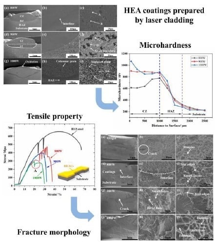
Phase Evolution, Microstructure and Mechanical Property of AlCoCrFeNiTi High-Entropy Alloy Coatings Prepared by Mechanical Alloying and Laser Cladding

School of Mechanical Engineering, Jiangsu University, Zhenjiang 212013, China
*
Author to whom correspondence should be addressed.
Metals 2019, 9(10), 1036; https://doi.org/10.3390/met9101036
Submission received: 6 August 2019 / Revised: 7 September 2019 / Accepted: 16 September 2019 / Published: 24 September 2019

Abstract

:
AlCoCrFeNiTi high-entropy alloy coatings (HEACs) were prepared by mechanical alloying (MA) and laser cladding (LC) process on H13 hot-working die steel substrate. Phase evolution, microstructure, and mechanical properties of the alloyed powder and HEACs were investigated in detail. The final milling AlCoCrFeNiTi coating powders exhibited simple body centered cubic (BCC) phase and mean granular size of less than 4 μm. With the increase of heat input of the laser, partial BCC phase transformed into minor face centered cubic (FCC) phase during LC. AlCoCrFeNiTi HEACs showed excellent metallurgical bonding with the substrate, and few defects. Moreover, the microhardness of AlCoCrFeNiTi HEACs reached 1069 HV due to the existence of the hard oxidation and the second phase grains, which are about five times that of the substrate. The laser surface cladding HEACs exhibited deteriorated tensile property compared with that of the substrate and the fracture generally occurred in the region of HEACs. The fracture mechanism of AlCoCrFeNiTi HEACs was dominated by the comprehensive influence of brittle fracture and ductile fracture.

Graphical Abstract

1. Introduction

In recent years, multi-component high-entropy alloys (HEAs) put forward by Yeh et al. have attracted wide interest and attention from different fields due to their excellent performances, and the mechanism is worth exploring [1,2,3]. HEAs break the bottleneck stage of design strategy for conventional alloy, which is based on one or two primary components and other minor elements to tailor the microstructure and properties. Compared with conventional alloy, the HEAs are defined as containing five to thirteen elements and the concentration of every element ranges from 5 to 35 at.%.
However, further research on HEAs found that such HEAs did not develop numerous intermetallic compounds and other complex structural phases during solidification suggested by existing metallurgy theory. Opposite to the expectations, HEAs tended to produce simple body centered cubic (BCC) and face centered cubic (FCC) solid solutions and, thus, reduced the numbers of phases, which can be attributed to the influence of the high configuration entropy in HEAs [4,5,6,7]. The outstanding properties, such as high microhardness and tensile strength [8,9], excellent wear resistance [10,11,12], superior corrosion resistance [13,14], and unique magnetic properties [15,16], offer potential applications for HEAs.
The strict correlation between mechanical property and the microstructure of HEAs have been studied by many scholars. It can be summarized that yield strength of FCC HEAs usually were in the range of 150–350 MPa at room temperature. Under the coupled effects of Hall-Petch and precipitation strengthening, Al0.3CrCoFeNi HEA showed ultimate tensile strength about 840 Mpa and excellent ductility of 45% elongation [17,18]. With the refinement of grain size, the CrMnFeCoNi HEA showed increasing yield strength, high fracture strength, and decent ductility [19].
Nowadays, HEAs are always produced by various routes, such as vacuum arc melting casting for bulk HEAs, magnetron sputtering, and laser cladding (LC) for film HEAs, and mechanical alloying (MA) for HEAs powder. Almost all of the bulk HEAs are fabricated by arc melting casting, which limits the shapes and sizes of samples and also needs repeated casting for uniform dispersion of elements. LC can meet the requirements of fabricating high-entropy alloy coatings (HEACs) thanks to its rapid cooling characteristics, which are beneficial in reducing atomic diffusion and accelerating solidification. In addition, the laser cladding coatings can realize good metallurgical bonding with substrates [15,20]. Przestacki et al. developed effective cutting parameters of laser-assisted machining technology to improve the surface quality of coatings fabricated by laser cladding [21]. In addition, topography analysis and simulation based on the optical method were developed to analyze the surface texture after laser cladding [22]. Bartkowska et al. adopted laser modification technology to obtain high microhardness and excellent wear resistance composite coatings [23]. Thus, in this paper, microstructure of HEACs fabricated by LC was systemically investigated. Moreover, MA is a widely used non-equilibrium powder solid alloying route for synthesizing HEA powders, which is conducive to expanding mutual solid solubility between the initial elements to form a simple solid solution more easily than casting. In this paper, phase evolution, microstructure of AlCoCrFeNiTi HEAs during MA, and LC processes under different parameters were intensively investigated, as well as mechanical properties and microstructure of HEACs after LC.

2. Experimental Procedures

2.1. Preparation of the HEA Powders and Coatings

Equiatomic elemental powders of Al, Co, Cr, Fe, Ni, and Ti with purity higher than 99.9% and particle size of less than 54 µm (300 mesh) were mechanically alloyed to synthesize AlCoCrFeNiTi HEA powders. The wet milling process was carried out in a planetary ball mill machine (YXQM-2L, MITR, Changsha, China) for 20 h at 300 rpm under argon atmosphere and then placed in a vacuum dryer for 6 h at 80 °C for the next process of LC. High performance stainless steel vials and balls were utilized as the milling media and the ball-to-powder weight ratio was 10:1. In order to confirm the phase evolution of powders during milling, powder samples were taken out after milling for 0, 1, 2, 4, 8, 12, 16, and 20 h, respectively. AISI (American Iron and Steel Institute) H13 hot-working die steel (composition: 0.38 wt.% C, 0.39 wt.% Mn, 1.05 wt.% Si, 5.13 wt.% Cr, 1.3 wt.% Cr, and Fe balance) with dimensions of 100 mm × 80 mm × 10 mm was selected as the substrate material. Before LC, the substrates surface was treated by a grinding machine to remove oxide and increase roughness and eventually ultrasonically cleaned in acetone.
The 20 h as-milled alloy powders with the thickness of 1.5 mm were preplaced on the surface of cleaned H13 substrates by Polyvinyl alcohol binder. The 6000 W fiber laser with a 1070 nm wavelength (TruDisk6002, TRUMPF, Beijing, China) was employed to fabricate single-bead and multiple-bead HEA coatings. The processing parameters were as follows: Laser power (P) of 800 W, 900 W, 1000 W, spot diameter (D) of 3 mm, and scanning speed (V) of 6 mm/s. The tensile test samples were scanned by multiple-bead lap, and the lap rate was 50%. Argon was used as a protection gas with a flow rate 10 L/min during LC process.

2.2. Characterization of the HEA Powders and Coatings

The milled powders and HEA coatings were analyzed by an X-ray diffraction (XRD, D8 ADVANCE, BRUKER, Karlsruhe, Germany) with Cu Kα (λ = 0.154 nm) radiation generated at 40 kV and 40 mA. The XRD patterns were obtained in the 2θ range from 20° to 90° at a step of 5°/min. The microstructure of the HEA powders was observed by field emission scanning electron microscopy (FESEM, JSM-7001F, JEOL, Tokyo, Japan). The single-bead coatings under different parameters were cut into small cross sections for metallography. These samples were polished and then etched with aqua regia solution for microstructure observation and chemical compositions analysis under the scanning electron microscopy (SEM, S-3400N, Hitachi, Tokyo, Japan) coupled with energy dispersive spectrometry (EDS) operated at 15 KV and a working distance of 8 mm. The microhardness (HV) at different depths of the HEA coatings was measured with Vickers hardness testing machine (HXS-1000TAC, Shoufeng, Shanghai, China) with the load of 500 g for 15 s. Each depth region was tested 5 times to determine the average hardness value. The mechanical properties were evaluated by tensile tests on dogbone-shaped samples with a gauge length of 10 mm cut from multiple-bead coatings. Tensile tests were measured with an electronic universal testing machine (WDW-200, Wuxing, Shandong, China) at room temperature at the strain rate of 1×10⁻³ s−1. Three tensile tests were performed to obtain average value under the same parameters.

3. Results and Discussion

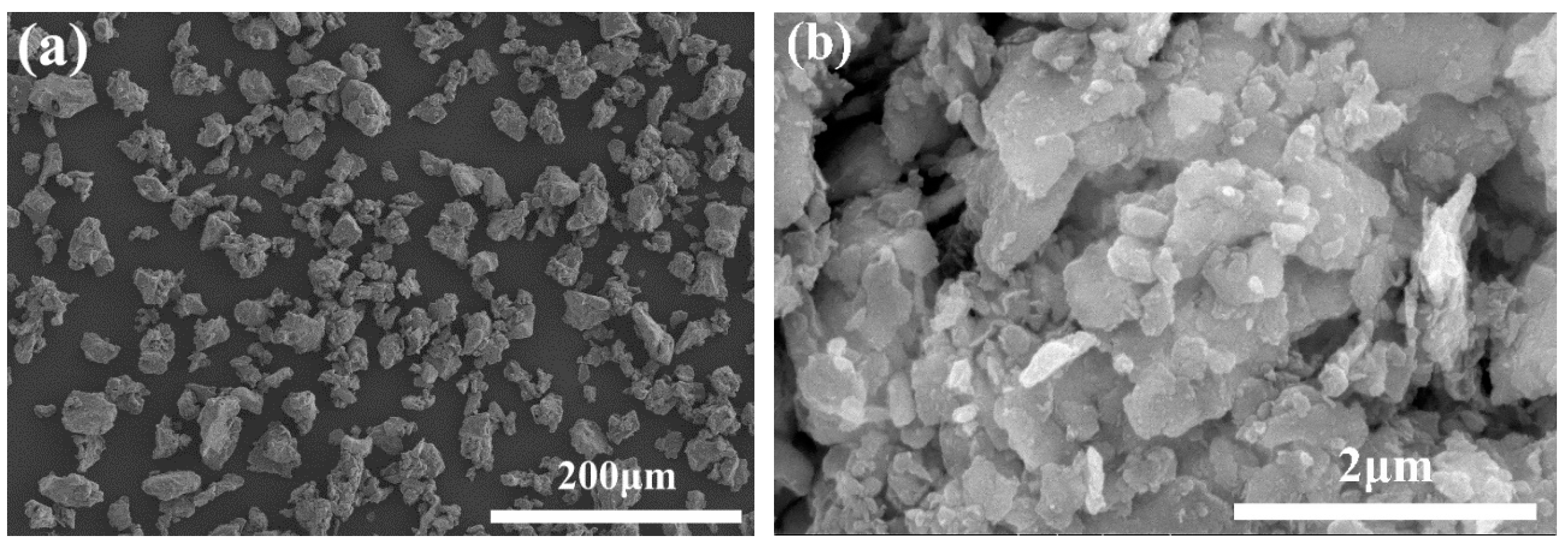
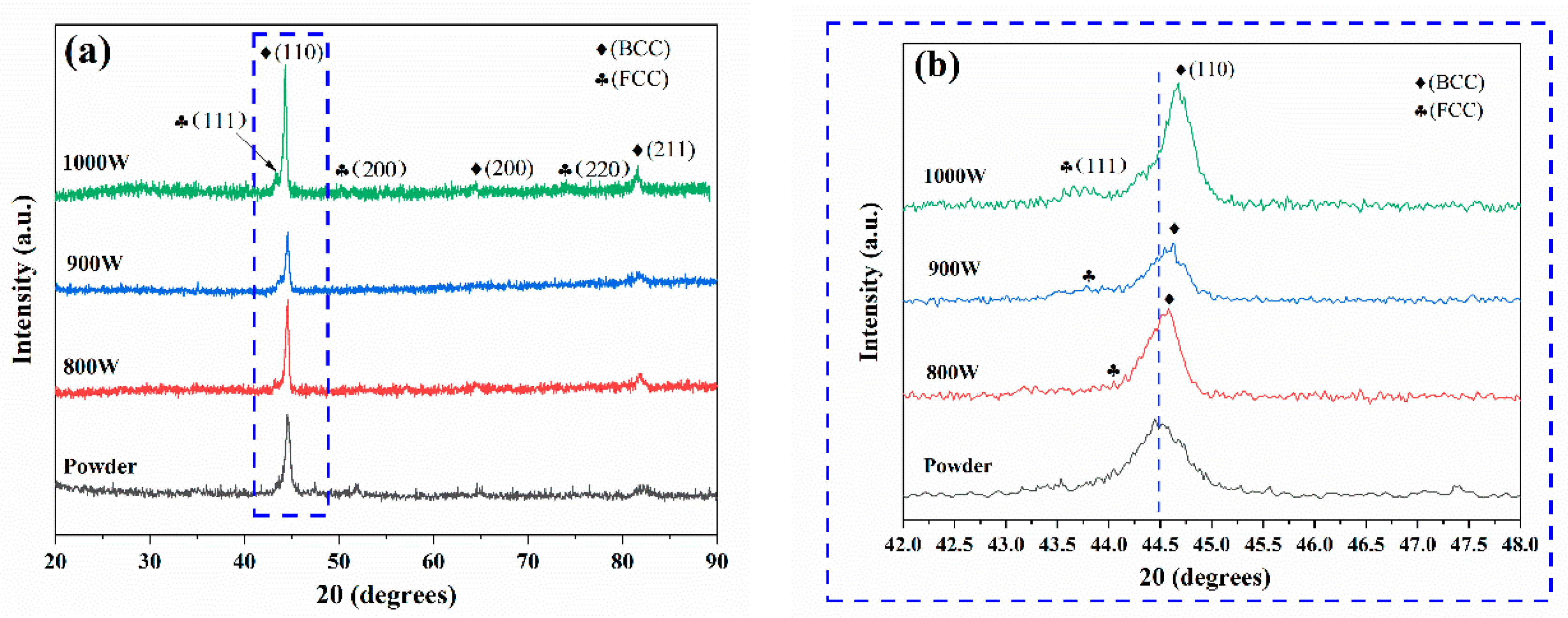
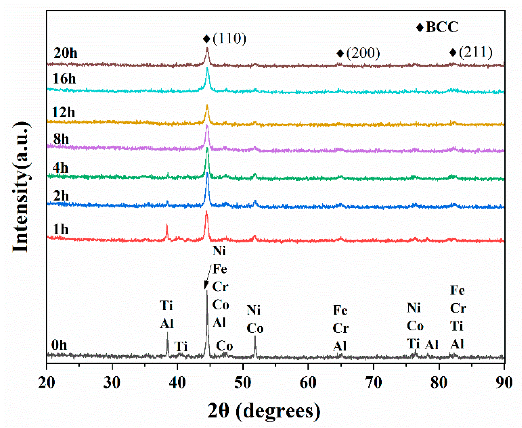
3.1. Phase Evolution and Microstructure of HEA Powders

Figure 1 shows the XRD patterns of AlCoCrFeNiTi HEA powders with different milling time. It is obvious that the initial powder included diffraction patterns of Al, Co, Cr, Fe, Ni, and Ti. As the milling time increased, diffraction intensity of HEA powders decreased quickly. The peaks of Al, Co, and Ni disappeared after 8 h of milling. Most of the diffraction peaks could hardly be seen after being milled for 20 h, while obvious peak broadening could be observed. The mechanically alloyed powder with milling duration more than 16 h showed formation of simple BCC solid solution structure. The peak intensity evolution of the pure element represented that it was completely dissolved in the BCC phase. It can be seen from Table 1. that rapid dissolution of Al, Co, and Ni elements could be attributed to their lower melting point compared with other elements. This was consistent with the results in Reference [24]. As the milling time extends to 20 h, the diffraction peak of (110) broadened a bit. It can be summarized from Figure 1 that the crystallite refinement was attributed to the circulation of crushing refinement and cold welding during the MA process. The simple BCC solid solution structure obtained by MA can be considered as the effect of high-mixing entropy which reduced the tendency of order and segregate, and formed the solid solution easily rather than intermetallics [25]. The FESEM image of the AlCoCrFeNiTi HEA powders after 20 h of milling is shown in Figure 2. The final powder showed the granular size of less than 4 μm and also contained plenty of flaked structure nanoparticles which contributed to uniform laser cladding for HEA powders. The repeated crushing and cold welding during the MA process reduced the crystalline size and promoted the diffusion and alloying among different elements.

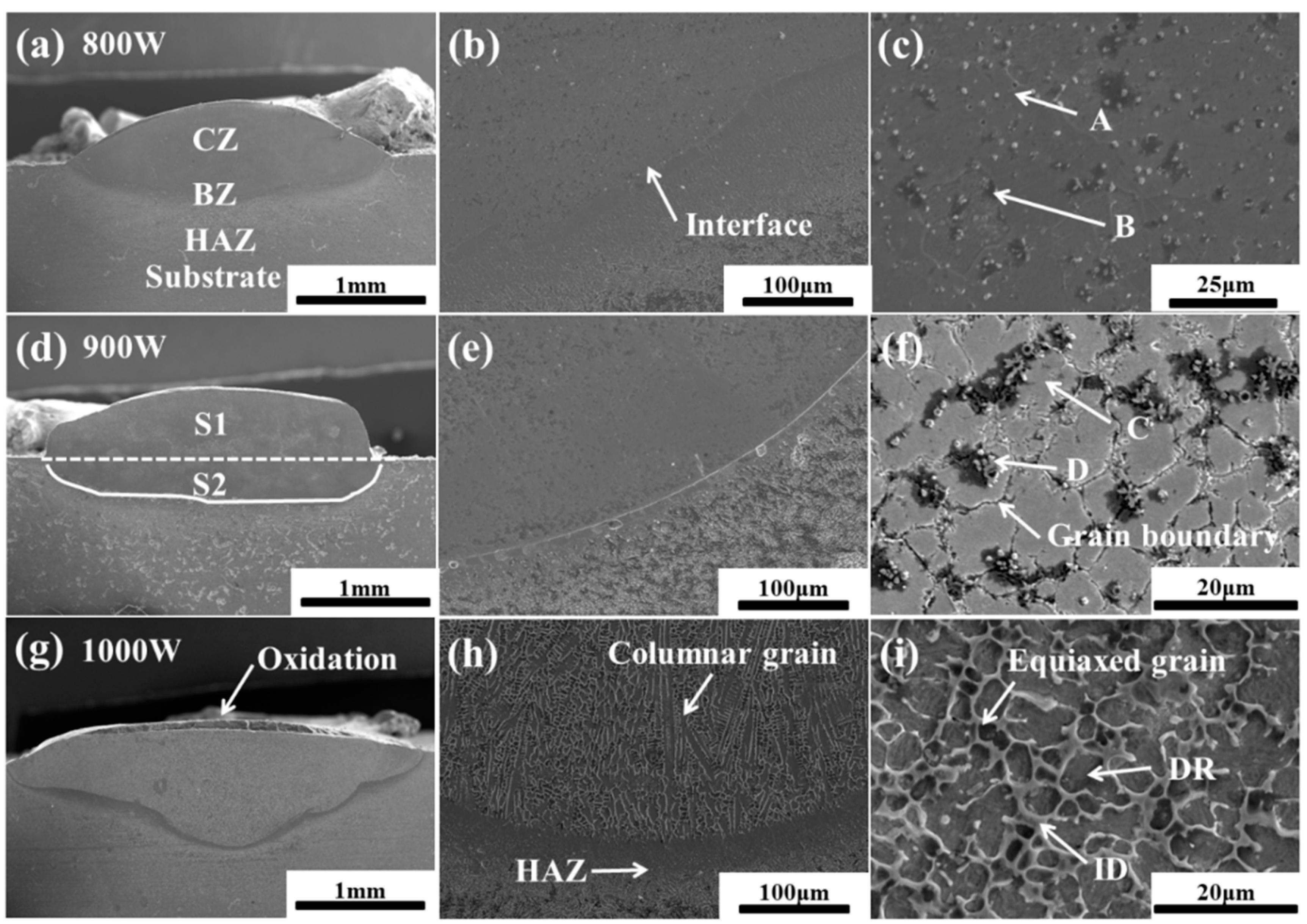
3.2. Microstructure of the AlCoCrFeNiTi HEACs
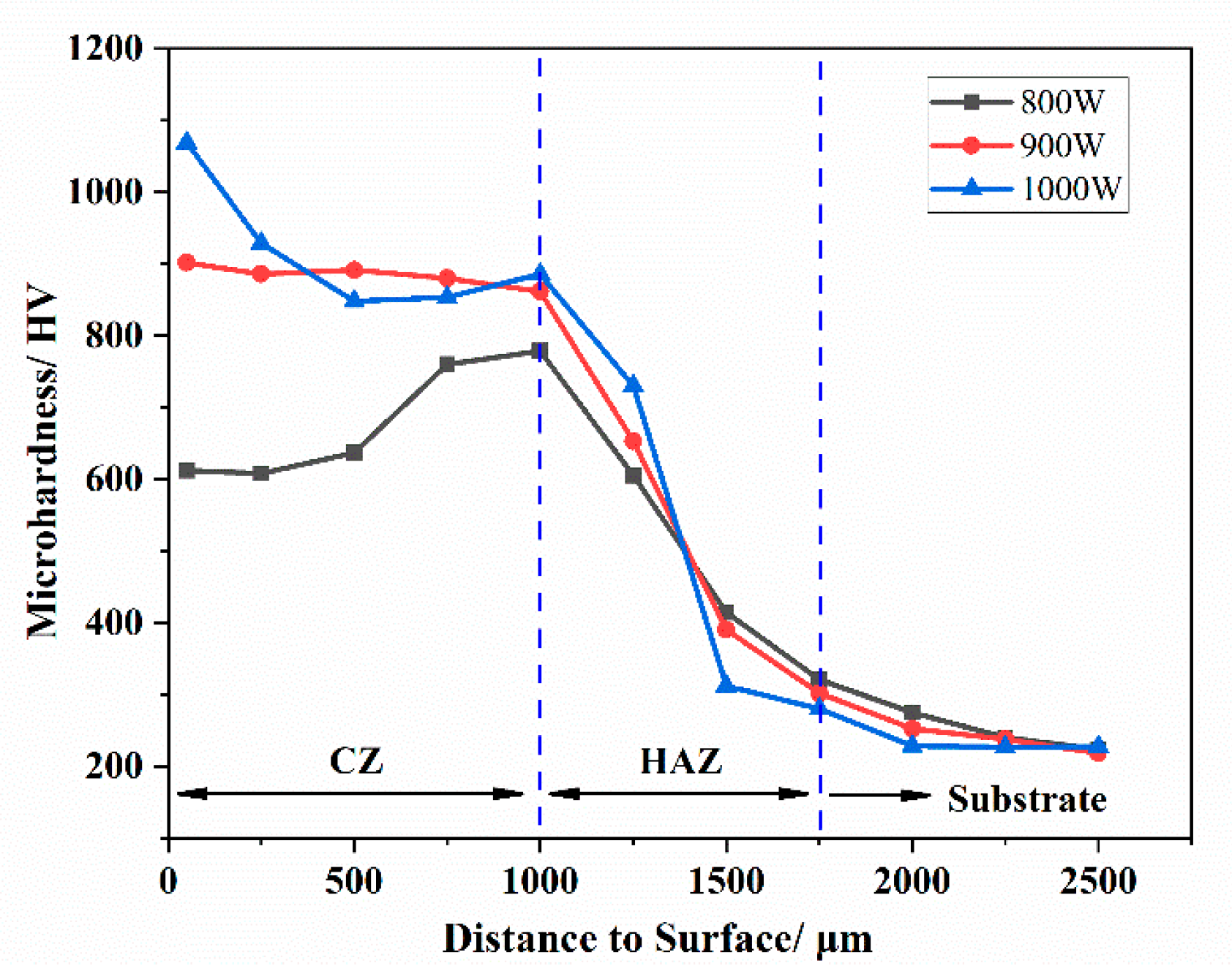
Figure 3 illustrates the cross-sectional microstructure of AlCoCrFeNiTi single-bead HEACs under different laser powers. It was obvious that morphology of HEAC presented an ellipsoid shape. From Figure 3a, it can be seen that the LC AlCoCrFeNiTi coating included the cladding zone (CZ), bonding zone (BZ), and heat-affected zone (HAZ). S1 and S2 represent the area of the coatings beyond the substrate and the melted substrate exhibited in Figure 3d, respectively. The dilution ratio (η) can be obtained by η = S2/(S1 + S2) [6]. By comparing Figure 3a,d,g, it can be concluded that as the laser power increased, the width of single-bead coatings and the dilution area of the substrate became larger, resulting in the increase of HEACs’ dilution ratio. Moreover, when laser power was 1000 W, the black oxidations were generated on the surface of HEACs, which were confirmed as TiO2 and Al2O3 by EDS and XRD results. As can be seen from Table 2, the mixing of Al and Ti had more negative mixing enthalpy and bonding energies among different elements, which formed the oxidations on the surface easily.
As seen from Figure 3b,e,h, the BZ between HEACs and H13 substrate shows dense coatings, excellent metallurgical bonding, and no cracks, porosities or defects. The BZ exhibited a span of less than 20 μm. As can be seen obviously in Figure 3h, the microstructure of HEAs coatings included columnar grains on the bottom of the CZ and uniform equiaxed grains on the top of the CZ. The growth direction of columnar grains was almost perpendicular to the interface of the coatings. The reason is that, with the increase of laser power, it provided higher temperature gradient to drive columnar grains to grow along the gradient. Meanwhile, equiaxed grains did not continue to grow due to low driving power away from the interface [7,8]. Figure 3c,f,i shows the microstructure of AlCoCrFeNiTi CZ, where typical dendrite and interdendrite structures (defined as DR and ID in the figures, respectively) could be observed. The chemical compositions of AlCoCrFeNiTi coatings are listed in Table 3. It is obvious that the content of Fe element increased. With the melting of the substrate, more elements migrated from the substrates to the HEACs, causing the compositions of the HEACs to deviate from the nominal compositions of the equimolar AlCoCrFeNiTi HEA. When the laser power was 800 W and 900 W, the fine flower-like particle structures emerged and were rich in Ti and C elements. The lower Al element content may be attributed to the burning and evaporation of Al powders during LC due to its low melting point.
Figure 4a exhibits the XRD patterns of the upper layer HEACs under different laser powers. As can be seen from Figure 4b, the (111) peak of HEACs moved toward the higher angle with the increase of laser power. According to Bragg’s law, 2dsinθ = nλ, where d is the interplanar spacing, and θ is the diffraction angle, λ is the wave length of the incident X-ray, n is a constant for diffraction [27]. In other words, high laser power increased the diffraction angle and then decreased the interplanar spacing. Hence, suitable laser power input may refine the grain size of HEACs [10]. Figure 4b shows more partial BCC phase evolved into stable FCC phase during LC process by comparing it with simple BCC solid phase in the powder after 20 h of milling. Due to the non-equilibrium process in the MA process, metastable supersaturated solid solutions formed more easily. So with the improvement of laser power, the heat input per unit area also increased rapidly, which promoted a more stable phase to form and reduce defects caused in MA [4,28,29].

3.3. Microhardness

Figure 5 illustrates the variation law of the microhardness of AlCoCrFeNiTi HEACs along the depth of the cross section. The microhardness curve shows a step-like decline, mainly corresponding to the CZ, the HAZ, and the substrate. As can be seen, the AlCoCrFeNiTi HEACs had higher hardness than the substrate under different laser powers, and the coating’s maximum hardness was 1069 HV, which is about five times larger than that of the H13 steel substrate (220 HV) and also much higher than the same composition alloy of as-sprayed coating with the value of 642 HV [30]. The maximum hardness appeared on the laser power of 1000 W, resulting from the existence of TiO2 and Al2O3 oxidation according to the results of EDS shown in Table 3, and the microhardness tendency from 800 W to 1000 W dropped quickly due to the increase of the dilution ratio. AlCoCrFeNiTi HEACs possess much greater hardness than the substrate, which can be attributed to two major reasons. Firstly, it can be seen from Table 3 that Al, Ti elements with larger radius than other elements, enhanced the lattice crystal distortion and the effect of solid solution strengthening [15,31]. Secondly, the formation of the hard oxidation or the second phase grains, such as TiC existing in the coating (Figure 3c,f,i), hindered the dislocation movement remarkably [32]. The existence of the TiC phase was beneficial to the wear resistance. Since the TiC phase was the main supporting point during the wear process, due to the high strength, hardness and bonding strength exist in the coating. The coating was, therefore, protected by the TiC phase. This may result in the excellent wear resistance of the materials.

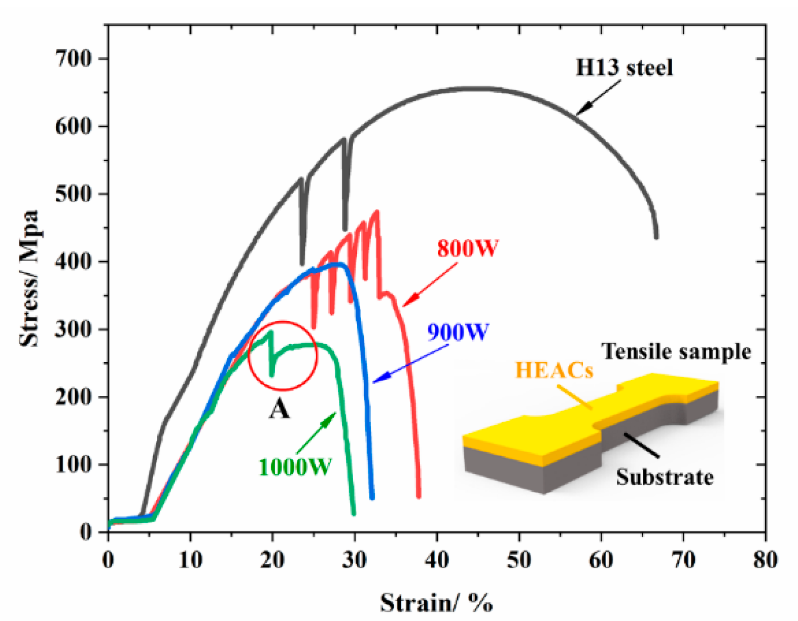
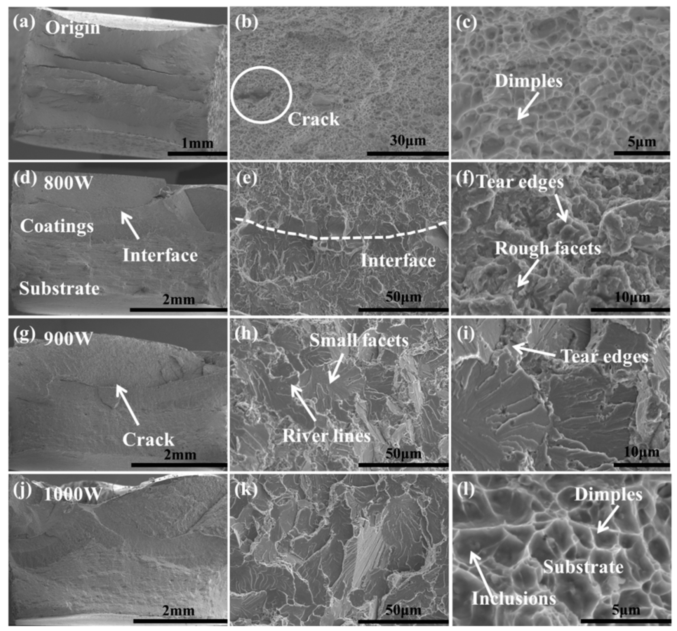
3.4. Tensile Properties

Figure 6 shows stress-strain curves of a smooth tensile sample and LC tensile samples with 1 mm thickness of AlCoCrFeNiTi HEACs under laser power of 800 W, 900 W and 1000 W, respectively. As shown in Figure 6, with the increase of laser power, the elongation and tensile property of samples decreased, respectively. The reason may be that the larger laser power caused higher dilution ratios which weakened the strengthening effects of AlCoCrFeNiTi HEACs and introduced large residual stress, causing strong stress concentration around cracks and micro-pores. This increased the expanding speed of defects, resulting in the drop of tensile strength [20,33]. Compared to no laser surface cladding sample, the laser surface cladding samples exhibited different stress-strain curves. According to Figure 6 and Table 4, region A shows a sudden decrease of stress of the laser surface cladding samples before arriving at the maximum stress and then a brief rise of stress until the samples broke. The reason may be that the BCC structure HEACs broke more easily than the H13 substrate. So, the partial fracture of HEACs caused the efficient load-bearing area of samples to decrease. Thus, the load-bearing of samples was reduced instantaneously, but due to the strengthening effect of the material itself after yielding, the short-term load still increased until laser surface cladding samples eventually broke [34].
Figure 7 illustrates fracture images of the H13 steel and laser surface cladding HEACs samples under different laser powers. It is straightforward to study fracture mechanism and toughness from fracture surfaces of HEACs. Compared with Figure 7a,d,g,j, the fractures always firstly occurred on the HEACs during the tensile test of laser surface cladding samples, which corresponded to the above inference and the sudden decrease on stress-strain curves. It may result that the major phase of AlCoCrFeNiTi HEACs is BCC phase with high strength and low plasticity that is easier to break. Figure 7b,c presents a typical ductile dimple fracture pattern and necking morphology of the H13 steel substrate. It was obvious that the inclusions located in some dimples, and with the increase of tensile load, dimples grew up and connected in series to a visible macro-crack shown in Figure 7b and eventually broke [35]. Fracture images of laser surface cladding HEACs under laser power of 800 W are shown in Figure 7d,e,f. The different fracture morphologies can be observed clearly around the interface. From high-magnified fracture image (Figure 7f), short tear edges and rough facets are obviously presented, proving the main fracture mechanism was the mixture of quasi-cleavage fracture and intercrystalline fracture [16,36]. Moreover, the H13 steel still exhibited ductile dimple fracture concluded from Figure 7l. Figure 7h,k illustrates similar fractography of laser surface cladding HEACs under laser power of 900 W and 1000 W, respectively. It was obvious that small facets surrounded by river lines formed on the fracture surface. However, tear edges appeared on the fracture surface with laser power of 900 W, which are typical of quasi-cleavage fracture. In addition, facets fracture surface with laser power of 1000 W are typical of the cleavage fracture which is associated with the low fracture toughness and brittle fracture [37,38]. This can be used to explain that laser surface cladding HEACs have lower strength than H13 steel in this research.

4. Conclusions

In this paper, the AlCoCrFeNiTi high-entropy alloy coatings was successfully fabricated by mechanical alloying and laser cladding on H13 steel. It revealed that the final milling high-entropy alloy powders for coatings exhibited BCC simple solid solution. The microstructure of final powder showed the granular size of less than 4 μm and also contained plenty of flaked nanoparticles. With the increase of laser heat input, AlCoCrFeNiTi high-entropy alloy coatings transformed from supersaturated BCC solid solutions into stable BCC phase and minor FCC phase. AlCoCrFeNiTi high-entropy alloy laser cladding coating exhibited high hardness due to the formation of the hard oxidation or the second phase grains such as TiC, the maximum surface microhardness was 1069 HV, which is about five times of that of the H13 steel. Compared with H13 steel, laser surface cladding AlCoCrFeNiTi high-entropy alloy decreased obviously in strength due to laser cladding thermal damage and comprehensive influence of brittle fracture and ductile fracture.

Author Contributions

Y.W. and R.L. designed the experimental process; W.Y. and J.M. performed the experiments and analyzed the data; W.Y. wrote the manuscript.

Funding

This work is supported by the National Natural Science Foundation of China (Grant No. 51575245), Research Foundation for Advanced Talents of Jiangsu University (No. 18JDG030), and the Industrial Center Student Innovation Practice of Jiangsu University (No. ZXJG2019026).

Conflicts of Interest

The authors declare no conflict of interest.

References

  1. Tsau, C.H.; Chin, T.S.; Yeh, J.W.; Chang, S.Y.; Shun, T.T.; Lin, S.J.; Chen, S.K.; Gan, J.Y. Nanostructured High-Entropy Alloys with Multiple Principal Elements: Novel Alloy Design Concepts and Outcomes. Adv. Eng. Mater. 2004, 6, 299–303. [Google Scholar]
  2. Chuang, M.H.; Tsai, M.H.; Wang, W.R.; Lin, S.J.; Yeh, J.W. Microstructure and wear behavior of AlxCo 1.5CrFeNi1.5Tiy high-entropy alloys. Acta Mater. 2011, 59, 6308–6317. [Google Scholar] [CrossRef]
  3. Guruvidyathri, K.; Murty, B.S.; Yeh, J.W.; Hari Kumar, K.C. Gibbs energy-composition plots as a tool for high-entropy alloy design. J. Alloys Compd. 2018, 768, 358–367. [Google Scholar] [CrossRef]
  4. Ogura, M.; Fukushima, T.; Zeller, R.; Dederichs, P.H. Structure of the high-entropy alloy AlxCrFeCoNi: Fcc versus bcc. J. Alloys Compd. 2017, 715, 454–459. [Google Scholar] [CrossRef]
  5. Vaidya, M.; Karati, A.; Marshal, A.; Pradeep, K.G.; Murty, B.S. Phase evolution and stability of nanocrystalline CoCrFeNi and CoCrFeMnNi high entropy alloys. J. Alloys Compd. 2019, 770, 1004–1015. [Google Scholar] [CrossRef]
  6. Senkov, O.N.; Miller, J.D.; Miracle, D.B.; Woodward, C. Accelerated exploration of multi-principal element alloys with solid solution phases. Nat. Commun. 2015, 6, 1–10. [Google Scholar] [CrossRef] [PubMed]
  7. Zhang, Y.; Zhou, Y.J.; Lin, J.P.; Chen, G.L.; Liaw, P.K. Solid-solution phase formation rules for multi-component alloys. Adv. Eng. Mater. 2008, 10, 534–538. [Google Scholar] [CrossRef]
  8. Bailey, N.S.; Katinas, C.; Shin, Y.C. Laser direct deposition of AISI H13 tool steel powder with numerical modeling of solid phase transformation, hardness, and residual stresses. J. Mater. Process. Technol. 2017, 247, 223–233. [Google Scholar] [CrossRef]
  9. Wang, J.; Liu, B.; Liu, C.T.; Liu, Y. Strengthening mechanism in a high-strength carbon-containing powder metallurgical high entropy alloy. Intermetallics 2018, 102, 58–64. [Google Scholar] [CrossRef]
  10. Wu, W.; Jiang, L.; Jiang, H.; Pan, X.; Cao, Z.; Deng, D.; Wang, T.; Li, T. Phase Evolution and Properties of Al2CrFeNiMox High-Entropy Alloys Coatings by Laser Cladding. J. Therm. Spray Technol. 2015, 24, 1333–1340. [Google Scholar] [CrossRef]
  11. Qiu, X.W.; Liu, C.G. Microstructure and properties of Al2CrFeCoCuTiNix high-entropy alloys prepared by laser cladding. J. Alloys Compd. 2013, 553, 216–220. [Google Scholar] [CrossRef]
  12. Shang, C.; Axinte, E.; Sun, J.; Li, X.; Li, P.; Du, J.; Qiao, P.; Wang, Y.; Ge, W.; Zhang, Z.; et al. Metastable high-entropy dual-phase alloys overcome the strength-ductility trade-off. Science 2017, 345, 1153–1158. [Google Scholar]
  13. Bao, Y.; Ma, A.; Zhao, J.; Jiang, J.; Ji, X. Slurry Erosion Behavior of AlxCoCrFeNiTi0.5 High-Entropy Alloy Coatings Fabricated by Laser Cladding. Metals 2018, 8, 126. [Google Scholar]
  14. Beyramali Kivi, M.; Hong, Y.; Asle Zaeem, M. A Review of Multi-Scale Computational Modeling Tools for Predicting Structures and Properties of Multi-Principal Element Alloys. Metals 2019, 9, 254. [Google Scholar] [CrossRef]
  15. Zhang, H.; Pan, Y.; He, Y.; Jiao, H. Microstructure and properties of 6FeNiCoSiCrAlTi high-entropy alloy coating prepared by laser cladding. Appl. Surf. Sci. 2011, 257, 2259–2263. [Google Scholar] [CrossRef]
  16. Wang, X.F.; Zhang, Y.; Qiao, Y.; Chen, G.L. Novel microstructure and properties of multicomponent CoCrCuFeNiTix alloys. Intermetallics 2007, 15, 357–362. [Google Scholar] [CrossRef]
  17. Gwalani, B.; Soni, V.; Lee, M.; Mantri, S.A.; Ren, Y.; Banerjee, R. Optimizing the coupled effects of Hall-Petch and precipitation strengthening in a Al0.3CoCrFeNi high entropy alloy. Mater. Des. 2017, 121, 254–260. [Google Scholar] [CrossRef]
  18. Lazzara, G.; Cavallaro, G.; Panchal, A.; Fakhrullin, R.; Stavitskaya, A.; Vinokurov, V.; Lvov, Y. An assembly of organic-inorganic composites using halloysite clay nanotubes. Curr. Opin. Colloid Interface Sci. 2018, 35, 42–50. [Google Scholar] [CrossRef]
  19. Liu, W.H.; Lu, Z.P.; He, J.Y.; Luan, J.H.; Wang, Z.J.; Liu, B.; Liu, Y.; Chen, M.W.; Liu, C.T. Ductile CoCrFeNiMox high entropy alloys strengthened by hard intermetallic phases. Acta Mater. 2016, 116, 332–342. [Google Scholar] [CrossRef]
  20. Qiu, X.W.; Zhang, Y.P.; Liu, C.G. Effect of Ti content on structure and properties of Al2CrFeNiCoCuTix high-entropy alloy coatings. J. Alloys Compd. 2014, 585, 282–286. [Google Scholar] [CrossRef]
  21. Przestacki, D.; Chwalczuk, T.; Wojciechowski, S. The study on minimum uncut chip thickness and cutting forces during laser-assisted turning of WC/NiCr clad layers. Int. J. Adv. Manuf. Technol. 2017, 91, 3887–3898. [Google Scholar] [CrossRef]
  22. Przestacki, D.; Majchrowski, R.; Marciniak-Podsadna, L. Experimental research of surface roughness and surface texture after laser cladding. Appl. Surf. Sci. 2015, 388, 420–423. [Google Scholar] [CrossRef]
  23. Bartkowska, A.; Pertek, A.; Popławski, M.; Bartkowski, D.; Przestacki, D.; Miklaszewski, A. Effect of laser modification of B-Ni complex layer on wear resistance and microhardness. Opt. Laser Technol. 2015, 72, 116–124. [Google Scholar] [CrossRef]
  24. Chen, Y.L.; Hu, Y.H.; Hsieh, C.A.; Yeh, J.W.; Chen, S.K. Competition between elements during mechanical alloying in an octonary multi-principal-element alloy system. J. Alloys Compd. 2009, 481, 768–775. [Google Scholar] [CrossRef]
  25. Zhang, K.B.; Fu, Z.Y.; Zhang, J.Y.; Wang, W.M.; Lee, S.W.; Niihara, K. Characterization of nanocrystalline CoCrFeNiTiAl high-entropy solid solution processed by mechanical alloying. J. Alloys Compd. 2010, 495, 33–38. [Google Scholar] [CrossRef]
  26. Miracle, D.B.; Senkov, O.N. A critical review of high entropy alloys and related concepts. Acta Mater. 2017, 122, 448–511. [Google Scholar] [CrossRef] [Green Version]
  27. Sun, G.; Tong, Z.; Fang, X.; Liu, X.; Ni, Z.; Zhang, W. Effect of scanning speeds on microstructure and wear behavior of laser-processed NiCr–Cr3C2–MoS2–CeO2 on 38CrMoAl steel. Opt. Laser Technol. 2016, 77, 80–90. [Google Scholar] [CrossRef]
  28. Shu, F.Y.; Liu, S.; Zhao, H.Y.; He, W.X.; Sui, S.H.; Zhang, J.; He, P.; Xu, B.S. Structure and high-temperature property of amorphous composite coating synthesized by laser cladding FeCrCoNiSiB high-entropy alloy powder. J. Alloys Compd. 2018, 731, 662–666. [Google Scholar] [CrossRef]
  29. Shu, F.; Yang, B.; Dong, S.; Zhao, H.; Xu, B.; Xu, F.; Liu, B.; He, P.; Feng, J. Effects of Fe-to-Co ratio on microstructure and mechanical properties of laser cladded FeCoCrBNiSi high-entropy alloy coatings. Appl. Surf. Sci. 2018, 450, 538–544. [Google Scholar] [CrossRef]
  30. Tian, L.H.; Xiong, W.; Liu, C.; Lu, S.; Fu, M. Microstructure and Wear Behavior of Atmospheric Plasma-Sprayed AlCoCrFeNiTi High-Entropy Alloy Coating. J. Mater. Eng. Perform. 2016, 25, 5513–5521. [Google Scholar] [CrossRef]
  31. Han, Z.; Chen, N.; Lu, S.; Luan, H.; Peng, R.; Xu, H.; Shao, Y.; Peng, Z.; Yao, K. Structures and corrosion properties of the AlCrFeNiMo0.5Tix high entropy alloys. Mater. Corros. 2018, 69, 641–647. [Google Scholar] [CrossRef]
  32. Baker, I.; Wu, M.; Wang, Z. Eutectic/eutectoid multi-principle component alloys: A review. Mater. Charact. 2019, 147, 545–557. [Google Scholar] [CrossRef]
  33. Wu, C.L.; Zhang, S.; Zhang, C.H.; Zhang, H.; Dong, S.Y. Phase evolution and cavitation erosion-corrosion behavior of FeCoCrAlNiTixhigh entropy alloy coatings on 304 stainless steel by laser surface alloying. J. Alloys Compd. 2017, 698, 761–770. [Google Scholar] [CrossRef]
  34. Zeng, C.; Tian, W.; Liao, W.H.; Hua, L. Study of laser cladding thermal damage: A quantified microhardness method. Surf. Coat. Technol. 2013, 236, 309–314. [Google Scholar] [CrossRef]
  35. Kang, B.; Kong, T.; Ryu, H.J.; Hong, S.H. The outstanding tensile strength of Ni-rich high entropy superalloy fabricated by powder metallurgical process. Mater. Chem. Phys. 2019, 235, 121749. [Google Scholar] [CrossRef]
  36. Fang, S.; Chen, W.; Fu, Z. Microstructure and mechanical properties of twinned Al0.5CrFeNiCo0.3C0.2 high entropy alloy processed by mechanical alloying and spark plasma sintering. Mater. Des. 2014, 54, 973–979. [Google Scholar] [CrossRef]
  37. Chen, W.; Fu, Z.; Fang, S.; Wang, Y.; Xiao, H.; Zhu, D. Processing, microstructure and properties of Al0.6CoNiFeTi0.4 high entropy alloy with nanoscale twins. Mater. Sci. Eng. A 2013, 565, 439–444. [Google Scholar] [CrossRef]
  38. Fu, Z.; Chen, W.; Xiao, H.; Zhou, L.; Zhu, D.; Yang, S. Fabrication and properties of nanocrystalline Co0.5FeNiCrTi0.5 high entropy alloy by MA-SPS technique. Mater. Des. 2013, 44, 535–539. [Google Scholar] [CrossRef]
Figure 1. XRD patterns of AlCoCrFeNiTi high-entropy alloys (HEAs) powders under different milling times.
Metals 09 01036 g001
Figure 2. Morphology of feedstock: (a) initial AlCoCrFeNiTi powder, (b) mechanically alloyed powder after 20 h milling.
Metals 09 01036 g002
Figure 3. Cross-sectional SEM images of single-bead AlCoCrFeNiTi HEACs. (a,d,g) Overall feature of cross section, (b,e,h) bonding zone, and (c,f,i) cladding zone, corresponding to different laser powers of 800 W, 900 W, and 1000 W, respectively.
Metals 09 01036 g003
Figure 4. XRD patterns of AlCoCrFeNiTi HEACs. (a) Samples under different laser powers, and (b) enlarged view of blue-dashed frame area.
Metals 09 01036 g004
Figure 5. Microhardness curves for AlCoCrFeNiTi HEACs along the depth of cross section for different laser powers.
Metals 09 01036 g005
Figure 6. Stress-strain curves for the H13 steel and laser surface cladding AlCoCrFeNiTi HEACs under the laser power of 800 W, 900 W, and 1000 W.
Metals 09 01036 g006
Figure 7. SEM images of fracture morphology of the H13 steel and laser surface cladding AlCoCrFeNiTi HEACs. (a,d,g,j) Overall fracture feature of cross section, (b,e,h,k) low magnification images, and (c,f,i,l) high magnification images, corresponding to origin substrate and different laser powers of 800 W, 900 W, 1000 W, respectively.
Metals 09 01036 g007
Table 1. Fundamental properties of elements in AlCoCrFeNiTi HEA [7,26].
ElementsAlCoCrFeNiTi
Atomic size (Å)1.431.251.281.271.251.46
Crystal structureFCCHCPBCCBCCFCCHCP
Melting point (°C)66014951857153514531660
Table 2. Mixing enthalpy (kJ/mol) between the elements of Al, Co, Cr, Fe, Ni, and Ti [7,26].
ElementsAlCoCrFeNiTi
Al-−19−10−11−22−30
Co -−4−10−28
Cr -−1−7−7
Fe -−2−17
Ni -−35
Ti -
Table 3. Energy dispersive spectrometry (EDS) results of the AlCoCrFeNiTi HEACs in different regions, as marked in Figure 3c,f,i (at.%).
RegionsAlCoCrFeNiTiCO
A5.6110.8713.2141.529.207.10 12.49
B8.727.139.6221.846.2346.46
C2.1911.5513.3751.169.0012.74
D1.152.324.1211.1310.9146.7323.64
DR8.556.7617.8640.349.656.24 10.6
ID2.7410.1515.8247.219.2914.79
Oxidation23.1 17.12 59.78
Nominal16.716.716.716.716.716.7
Table 4. Tensile test results for the H13 steel and laser surface cladding AlCoCrFeNiTi HEACs under the laser power of 800 W, 900 W, and 1000 W.
Substrate/CoatingsParametersYield Strength/MpaTensile Strength/MpaElongation at Break
H13 steel with thickness of 3.5 mm-490.286656.57167.30%
AlCoCrFeNiTi HEACs with thickness of 1 mm and H13 steel substrates with thickness of 2.5 mm800 W370.576473.7538.70%
900 W360.624396.29632.50%
1000 W284.074296.66730.20%

