Article

Electrochemical Behaviour of Chalcopyrite in Chloride Solutions

1
Laboratorio de Investigación de Minerales Sulfurados, Departamento de Ingeniería Metalúrgica y Minas, Universidad Católica del Norte, Avenida Angamos 0610, 1270709 Antofagasta, Chile
2
Hydrometallurgy Research Group, Department of Chemical Engineering, University of Cape Town, South Lane, Rondebosch 7701, South Africa
3
CPCM Research Group, Department of Materials Science and Physical Chemistry, University of Barcelona, Martí i Franquès 1, 08028 Barcelona, Spain
*
Author to whom correspondence should be addressed.
Metals 2019, 9(1), 67; https://doi.org/10.3390/met9010067
Submission received: 8 November 2018 / Revised: 31 December 2018 / Accepted: 6 January 2019 / Published: 11 January 2019
(This article belongs to the Special Issue Advances in Hydrometallurgy)

Abstract

:
Due to the depletion of oxidized copper ores, it necessitates the need to focus on metallurgical studies regarding sulphide copper ores, such as chalcopyrite. In this research, the electrochemical behaviour of chalcopyrite has been analysed under different conditions in order to identify the parameters necessary to increase the leaching rates. This was carried out through cyclic voltammetry tests at 1 mV/s using a pure chalcopyrite macro-electrode to evaluate the effect of scan rate, temperature, and the addition of chloride, cupric, and ferrous ions. Lastly, the feasibility of using seawater for chalcopyrite dissolution was investigated. An increase in the sweep rate and temperature proved to be beneficial in obtaining highest current densities at 10 mV/s and 50 °C. Further, an increase of chloride ions enhanced the current density values. The maximum current density obtained was 0.05 A/m2 at concentrations of 150 g/L of chloride. An increase in the concentration of cupric ions favoured the oxidation reaction of Fe (II) to Fe (III). Finally, the concentration of chloride ions present in seawater has been identified as favourable for chalcopyrite leaching.

1. Introduction

Nowadays chalcopyrite is processed mainly via concentration by flotation and subsequent pyrometallurgy. As a result of this last stage copper anodes with 99.6% purity are obtained [1] as well as slag and SO2 gas. One of the main challenges of smelters in Chile is to satisfy stricter environmental regulations. Furthermore; hydrometallurgy faces the depletion of copper oxides in operating fields and the reduction of copper grades. Therefore, the main challenge is the processing of copper sulphide ores, specifically chalcopyrite (CuFeS2) leaching. Chalcopyrite has been studied through various aqueous systems such as nitrate, ammonia, chloride and sulphate, with and without the presence of bacteria [2]. This would help to reduce energy and economic costs in the industry, as well as the operational projection of hydrometallurgical plants.
In addition to being the most abundant copper sulphide mineral in the earth’s crust, chalcopyrite is also very refractory to conventional leaching processes [3]. Fundamental studies of leaching and electrochemistry have indicated that the dissolution of chalcopyrite in acidic environments is an electrochemical reaction, which is dependent on the solution potential between 560–620 mV (SHE) where the chalcopyrite dissolution increases [4].
Investigations by Lu et al. [5], and later Yévenes et al. [6], have indicated that chloride ions would increase this solutions potential range, however, outside this range a product layer is formed on the mineral surface which inhibits or prevents the dissolution of chalcopyrite. Additionally, intermediate copper sulphide products, such as covellite (CuS) and chalcocite (Cu2S), would be formed under 550 mV (SHE), and these species can only be dissolved by increasing the solution potential. A Pourbaix diagram for CuFeS2 was illustrated by Cordova et al. [7] which shows that the dissolution of chalcopyrite occurs through its transformation in different intermediate sulphides (Cu5FeS4, CuS, Cu2S) and the dissolution of copper from chalcopyrite requires a pH lower than 4 and an oxidizing redox potential higher than 400 mV.
Different studies have indicated that a product layer will be formed on the surface of chalcopyrite above 620 mV (SHE) [4,7,8]. The presence of those products can stop or reduce the dissolution rate of chalcopyrite [7]. The controversy over the composition of this layer continues today. Different studies have found that passivation is caused by the formation of elemental sulphur [9]. Other studies indicate that they are iron precipitates, such as iron hydroxides, particularly jarosite [10,11] and even copper polysulphides or enriched copper sulphides [3,12]. Liu et al. [13] reported the formation of Cu2(OH)3Cl as a new passive layer formed in concentrations above 0.5 mol/L NaCl however, Senanayake [14] postulated that the formation of this product occurs at pH close to 3. Despite this, it is now widely accepted that the retardation in the rate of chalcopyrite dissolution is due to the formation of a sulphide layer, rather than elemental sulphur or iron oxides which is less reactive than chalcopyrite [8].
A recent electrochemical study [15] compared three leaching systems i.e., sulphuric, nitric, and hydrochloric acid. It was indicated that the highest current densities were obtained in chloride media, and after conducting SEM/EDS analysis and Raman microspectroscopy on the electrodes they restated that both covellite and sulphur formed on the surface of chalcopyrite. In the study conducted by Nicol et al. [16], a summary of the dissolution of chalcopyrite in chloride solutions was proposed. It is indicated that at a solutions potential below 550 mV (SHE) in the presence of copper, the chalcopyrite surface is converted into one that has the characteristics of covellite. Additionally, while the solution potential increases, the chalcopyrite and the surface layer of covellite are oxidized to produce copper (I) and elemental sulphur or thiosulphite as the initial oxidation products. It is further indicated that passivation is generated by the formation of a copper polysulphide as CuS2 when solution potential increases between 700 and 800 mV. Furthermore, at higher solution potential (over 1 V) dissolution occurs (transpasivation) and the polysulphide layer is oxidized and eliminates the passivating layer [16]. The presence of the chloride ion has been identified as a catalyst in the copper dissolution from chalcopyrite. An alternative source of chloride ions is seawater. This resource contains 20 g/L of chloride approximately. The use of seawater in Chilean copper mining takes on greater importance due to the geographical location of the deposits. The majority of copper mining in Chile is located in the Atacama Desert (the driest place in the world). As a strategic option in copper mining in Chile, seawater as the water source is capable of sustaining about 49% of the total water required for the copper industry in Chile for 2028 [17]. Thus, the use of seawater in sulphide ore leaching processes would be beneficial given the synergy provided by the presence of chloride in the system. In the present study, the electrochemical behaviour of chalcopyrite in chloride solutions was investigated. Experiments were performed at 25 and 50 °C using seawater and deionised water as solvents. A comparison has been made with the electrochemical behaviour of chalcopyrite in deionised and seawater, under the same concentration of cupric ions, ferrous ions, and sulphuric acid.

2. Materials and Methods

For this electrochemical study, the cyclic voltammetry technique was used. A potential sweep was run from the mixed potential, initially measured by open-circuit potential tests, up to a higher limit potential. The oxidation reactions occurred during this sweep, known as the anodic sweep. This was followed by a cathodic sweep which was run from the upper potential to a defined lower potential: in this sweep the reduction reactions occurred. On completion, the cycle ended at the mixed potential [18].

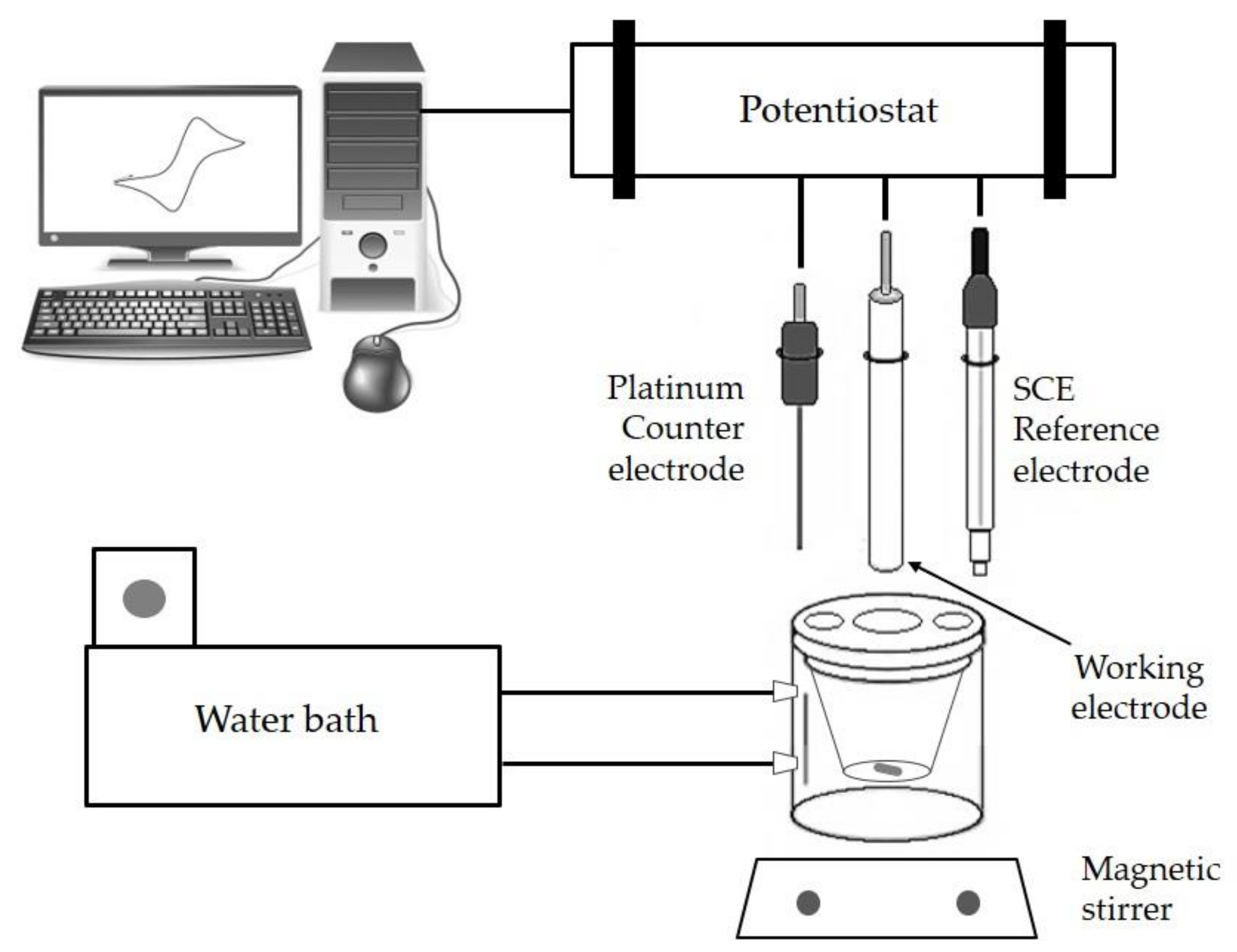
2.1. Instrumentation Used

Electrochemical measurements were carried out using a Voltalab PGZ100 potentiostat (Radiometer Analytical SAS, Villeurbanne, Rhone Alpes, France) with a Voltamaster VM4 software (Version F, Radiometer Analytical SAS, Villeurbanne, Rhone Alpes, France).
The electrochemical set-up consisted of a thermostatted cell and three electrodes, which is illustrated in Figure 1. The working electrode was fabricated with a pure chalcopyrite sample. XRD analysis indicated the presence of 99% of chalcopyrite (according to Figure 2). For XRD analysis, the sample was ground in an agate mortar to a size less than 45 µm and analysed in an automatic and computerized X-ray diffractometer Siemens model D5000 (Bruker, Billerica, MA, USA), with an analysis time of one hour. The ICDD (International Centre for Diffraction Data, Version PDF-2, Bruker, Billerica, MA, USA) database was used to identify the species present, and the TOPAS (Total pattern analysis software, Version 2.1, Bruker, Billerica, MA, USA) was used for quantification. The XRD equipment uses an internal corundum standard. Additionally, atomic absorption spectrometry (AAS) analysis showed 34% of copper in the sample. The reference electrode used was Hg/HgCl (calomel) which contained a saturated solution of KCl (supplied by a radiometer) and a radiometer platinum auxiliary electrode was used, which had inert characteristics. Fifty millilitres of solution were placed into the cell for each test. The solution was stirred at 60 rpm and the temperature was regulated using a thermostatted jacket. All the potentials shown are quoted with respect to the standard hydrogen electrode (SHE).

2.2. Methodology

Open circuit potential (OCP) measurements have been carried out using both platinum and chalcopyrite electrodes in order to identify the behaviour of solution and mixed potential respectively, followed by cyclic voltammetry. The aim is to identify peak potentials in which anodic and cathodic reactions will occur.
OCP was performed for a period of 30 min before each cyclic voltammetry test in order to stabilize the rest potential. At the end of each OCP, a cyclic voltammetry test was performed with the platinum inert electrode to obtain the current densities with respect to the solution potential. This test was carried out prior to the chalcopyrite electrode tests, in order to identify the reactions that take place in the solution. The limit potentials in cyclic voltammetry tests for both the platinum inert electrode and the chalcopyrite working electrode were −500 and 1200 mV.

2.3. Parameters Assessed

The sweep rate was studied at 1, 2 and 10 mV/s using a base case solution with 20 g/L [Cl]; 0.5 g/L [Cu2+]; 1 g/L [Fe2+]; and pH 1 adjusted with sulphuric acid at 25 °C for all tests.
In addition, the effect of different reagents was evaluated at 25 °C using the base case solution. Chloride concentration was studied at 0, 20, 50, 100 and 150 g/L using reagent-grade NaCl. In this case, as well as the tests below, the scan rate was 1 mV/s.
The effect of ferrous ions was evaluated at 0, 1, 5, and 10 g/L [Fe2+] using reagent-grade FeSO4·7H2O and the effect of cupric ions was studied varying the concentrations between 0; 0.5; 3 and 10 g/L [Cu2+] using reagent grade CuSO4·5H2O.
The temperature was evaluated at 25, 35, and 50 °C using the base case electrolyte (20 g/L [Cl], 0.5 g/L [Cu2+], and 1 g/L [Fe2+] at pH 1).
Lastly, the effect of seawater was evaluated, using five different solutions, all adjusted to pH 1 with sulphuric acid. Seawater was collected from the seashore of Antofagasta (Chile). AAS analysis determined 19.5 g/L [Cl] in the seawater, which was filtered before the test. The electrolytes used are detailed below:
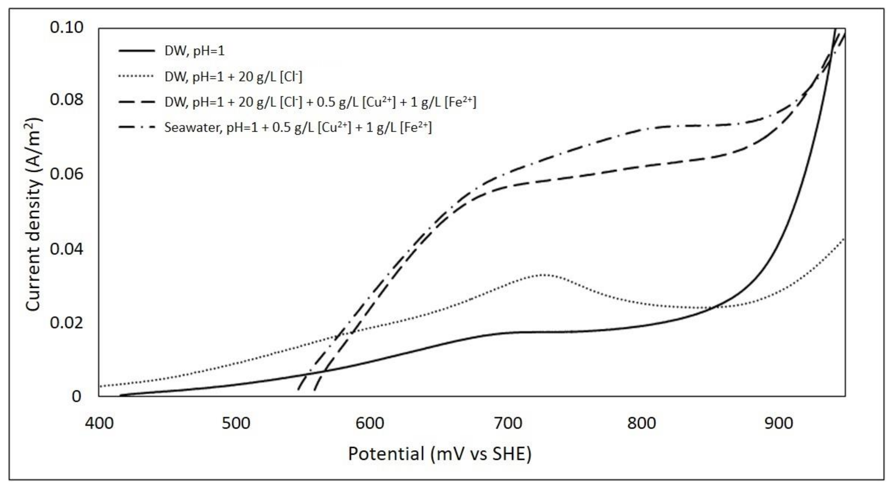
  • Deionised water (DW) at pH 1
  • DW at pH 1 and 20 g/L [Cl] (from NaCl)
  • DW with concentrations of 20 g/L [Cl], 0.5 g/L [Cu2+], 1 g/L [Fe2+] at pH 1
  • Seawater with concentrations of 0.5 g/L [Cu2+], 1 g/L [Fe2+] at pH 1

3. Results and Discussions

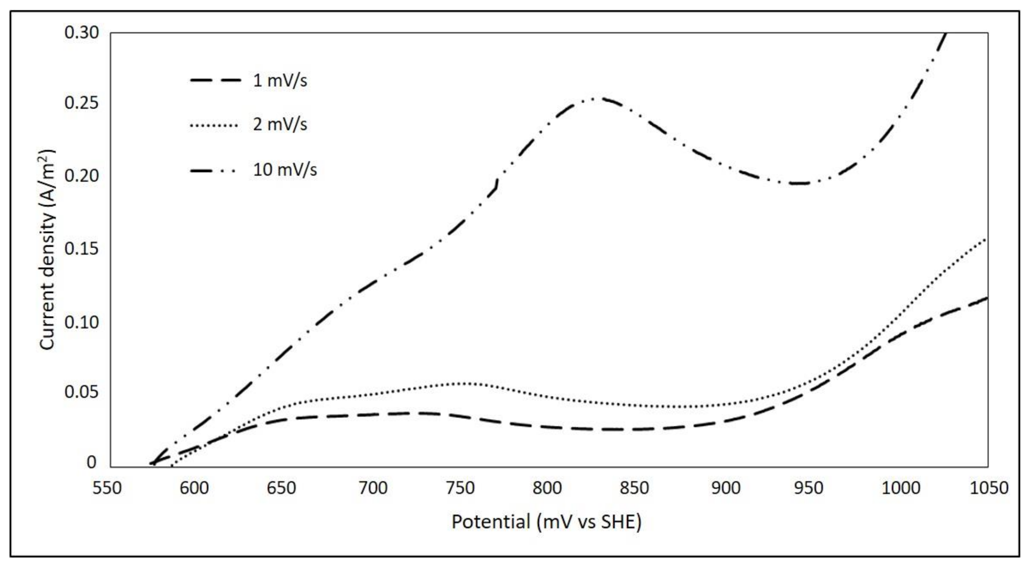
3.1. Effect of Sweep Speed

Figure 3 shows the anodic sweep for the chalcopyrite electrode. It can be seen that the range, where the chalcopyrite dissolution is maximized, is between 570 and 750 mV for the sweep rate of 1 and 2 mV/s. There is no significant difference between the current densities obtained, reaching a maximum of 0.05 A/m2 at 750 mV. When 10 mV/s was used, higher current densities were obtained, reaching values close to 0.25 A/m2 at a maximum potential of 830 mV. Under these conditions, the increase in the current density of chalcopyrite is reached within a range of 570 to 830 mV.
According to studies conducted by Viramontes-Gamboa et al. [19], a sufficiently slow sweep speed (between 0.5 and 2 mV/s) allows the system to complete the formation of the product layer, therefore the current density will be affected by the formation of this layer on the surface of the electrode. On the other hand, using a fast enough sweep speed (over 5 mV/s), the product layer cannot be completely formed. Subsequent tests were carried out maintaining a sweep speed of 1 mV/s in order to visualize of the passivation zone, where the current density decreases within an anodic polarization.

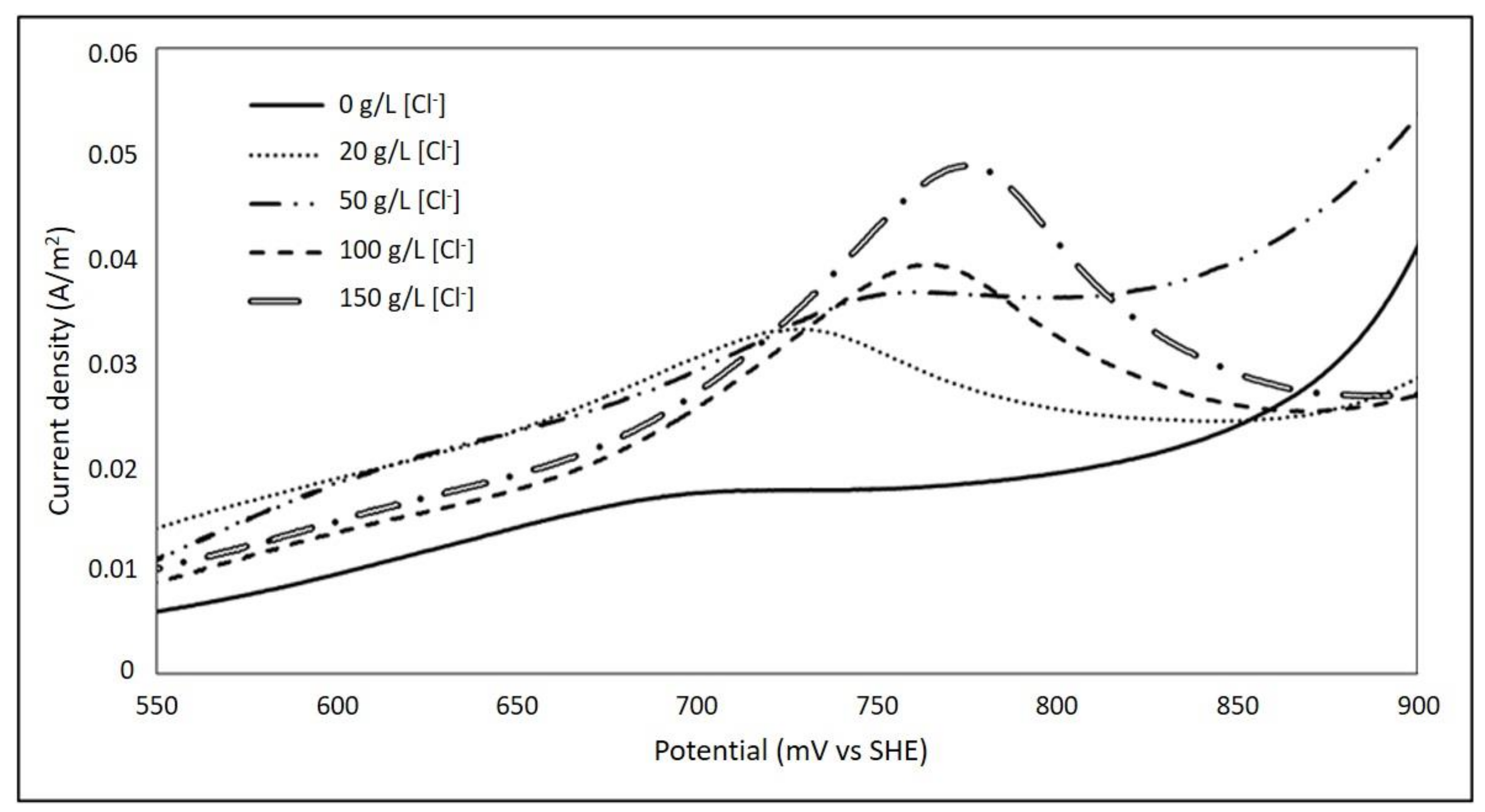
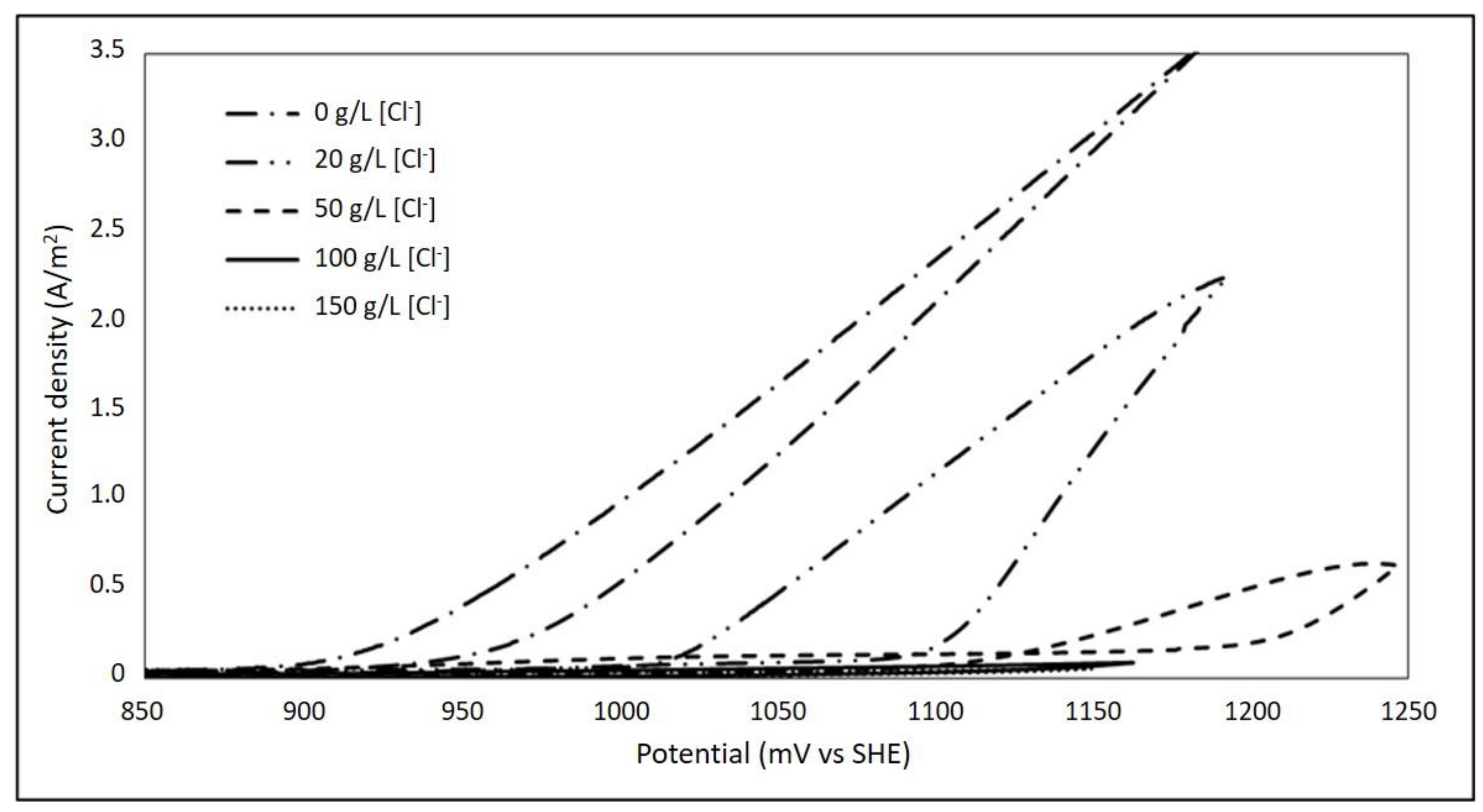
3.2. Effect of Chloride Ions

The effect of chloride ions was analysed to compare the behaviour of current density on the chalcopyrite electrode. Figure 4 illustrates that an increase in the concentration of chloride ions up to 150 g/L [Cl] resulted an increment in current density, reaching a maximum value of 0.05 A/m2, thus increasing the dissolution kinetics of chalcopyrite. The above is observed at solution potential of 780 mV with 150 g/L of chloride ions.
The solution potential range, where a higher current density is reached, is between 670 and 780 mV for all chloride concentrations evaluated. These results are consistent with those obtained by Lu et al. [5], who indicated that chloride ions increase the oxidation of chalcopyrite.
Similar results were obtained by Nicol et al. [16] and attributed that the oxidation peaks obtained after passivation (between 750 and 850 mV) could be associated with the oxidation of CuS2 or a similar polysulphide. The above mentioned findings were obtained in the present research is presented in the Figure 5, the maximum current density obtained is over 900 mV. Similar results are obtained by Nicol [20] at potentials above 950 mV greater currents were observed in sulphate than chloride solutions.

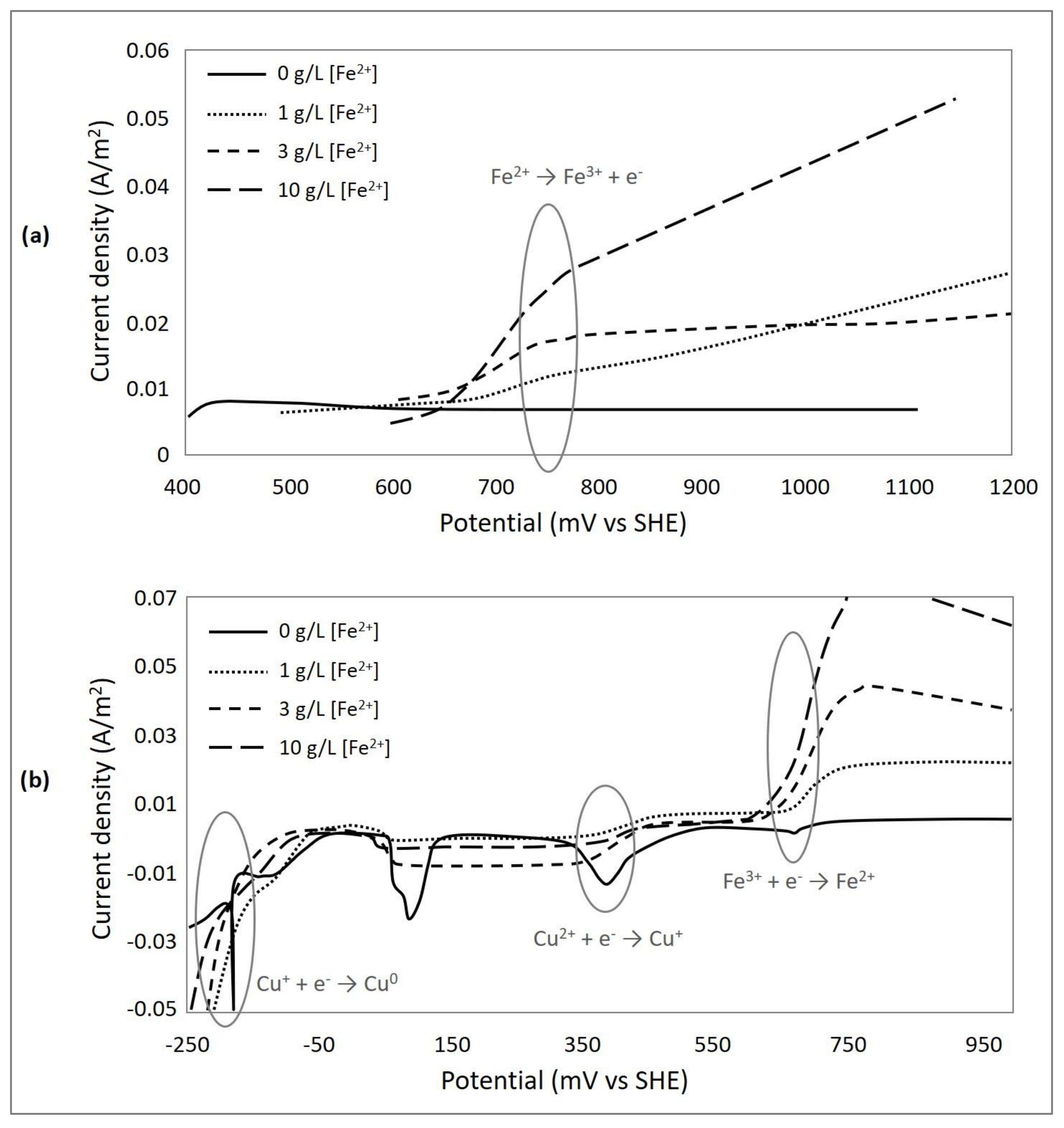
3.3. Effect of Ferrous Ions

In Figure 6, two oxidation peaks are observed. The first peak corresponds to the dissolution of the chalcopyrite that occurs at approximately 670 mV, obtaining a maximum current density of 0.15 A/m2. These results are consistent as reported by Beltrán et al. [21] under similar conditions. The above indicates that the dissolution of the chalcopyrite increases while increasing the concentration of ferrous ions in solution. A study conducted by Hiroyoshi et al. [22], observed that the chalcopyrite solution was more effective in ferrous sulphate medium than in ferric sulphate. The electrochemical studies carried out by Elsherief [3] have shown the positive effect of ferrous ions. However, other authors give more importance to the Fe (II)/Fe (III) ratio, while other studies refute this claim [6].
The second oxidation peak, which is observed at 750 mV, corresponds to the ferrous to ferric oxidation reaction. This is confirmed by the results obtained in tests with an inert electrode, which can be seen in Figure 7a.
In anodic polarization, no reaction occurs in the absence of ferrous ions. On the other hand, the solution with 1 g/L of ferrous ions forms a small peak at 750 mV, and this peak is observed when the concentration of ferrous ions increases. Furthermore, Figure 7b shows three reduction peaks. The first peak at 700 mV corresponds to the reduction reaction of Fe (III) to Fe (II), the second peak at 400 mV which corresponds to the reduction reaction of Cu (II) to Cu (I) and finally at −100 mV the peak relates to the reduction reaction of Cu (I) to Cu0. Similar results of oxidation and reduction, to the same potentials under the same solution conditions have been obtained by Beltrán et al. [21]. In addition, Hiroyoshi et al. [23], proposed a model in which an intermediate copper sulphide is formed, such as Cu2S in the region below a critical potential, which depends on the concentration of the ferrous and cupric ions.

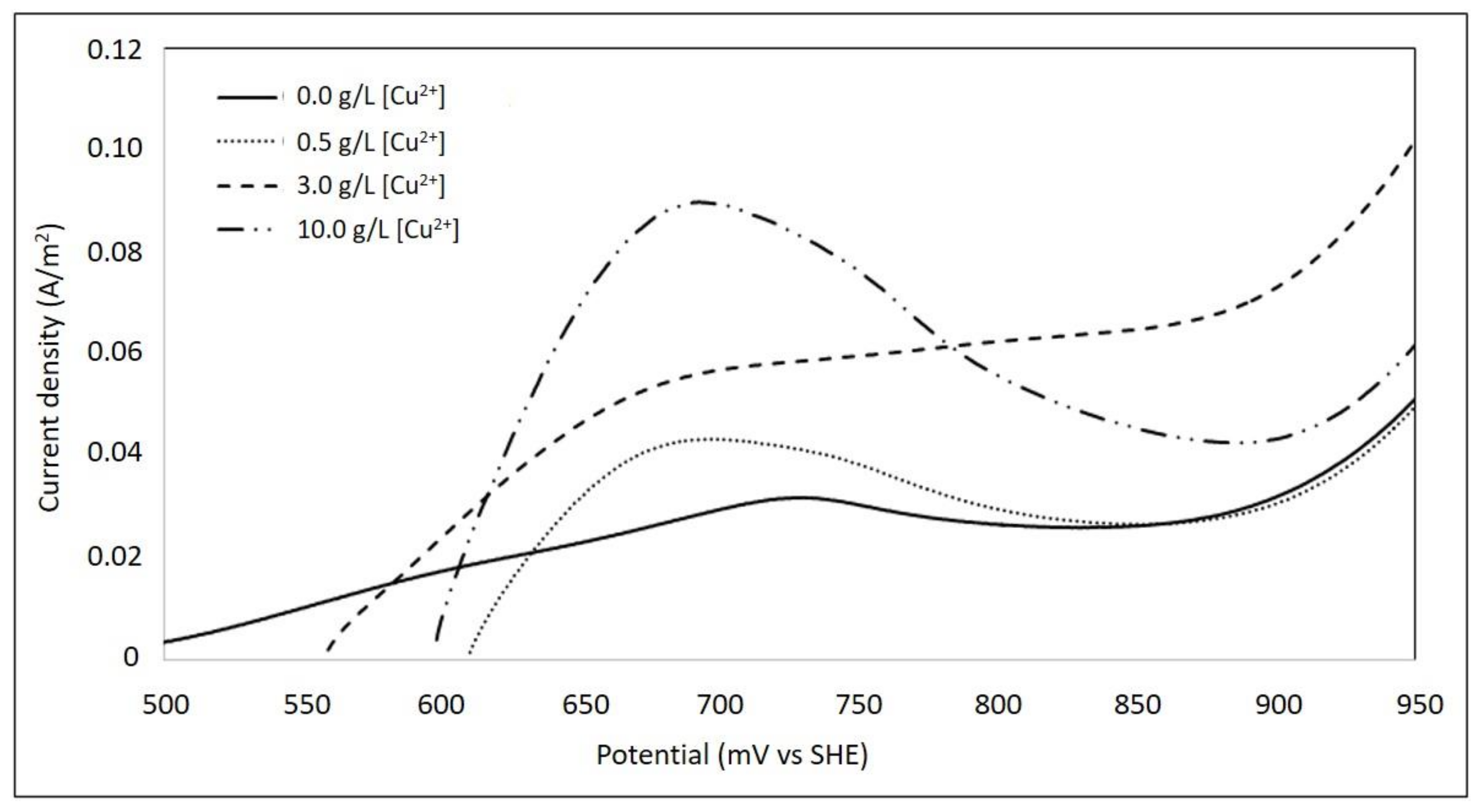
3.4. Effect of Cupric Ions

The results obtained are shown in Figure 8. It is observed that a rise in cupric concentration, from 0 to 10 g/L, generates an increase in current density. To perform this analysis it is necessary to identify the oxidation peaks that occur in the system. Figure 8 shows two peaks of oxidation, the first would correspond to the dissolution of chalcopyrite at potentials close to 670 mV and an oxidation potential of ferrous ions that occurs at potentials close to 750 mV.
These results are compared with an inert platinum electrode test (Figure 9a). The test determines a peak of ferrous ion oxidation near the 750 mV potential, which agrees with the findings as obtained by Beltrán et al. [21]. An increase in the concentration of cupric ion generated an increment in the current density corresponding to the oxidation peak of Fe (II) to Fe (III). This indicates that the presence of copper ions favours the oxidation of the ferrous ion acting as catalyst of the reaction.
The research of Hiroyoshi et al. [24] indicated that the coexistence of copper and ferrous ion promotes the dissolution of chalcopyrite at a potential lower than 550 mV (SHE). However, the absence of these ions, generates a passivating layer of high resistance to the dissolution of chalcopyrite. In the study by Yévenes et al. [6] tests were performed using a 0.2 M HCl solution with different concentrations of cupric ions. Results indicate that an increase in the concentration of cupric ions does not generate an increase in the rate of leaching, but a small amount (0.1 g/L) of cupric ions catalyses the leaching of copper sulphides such as chalcopyrite.
Recent studies by Veloso et al. [25] developed leaching tests in chloride media and evaluated the effect of cupric and ferric ions. They achieved twice as much dissolution in tests with cupric ions compared tests with ferric ions. The authors indicate that this is due to faster and reversible reduction of Cu (II) to Cu (I) compared to the Fe (II)/Fe (III) couple.
In addition, the stability of Cu (I) in solution is due to its strong association to form chlor-complexes, which have greater stability with Cu (I) than iron ions [26,27]. These complexes would rapidly oxidize to Cu (II), resulting in an oxidizing agent in the reaction [6].
Figure 9b shows the curve in the cathode direction, i.e., where the reduction reactions occur. The peaks of the current density obtained indicate the potentials where the reduction reactions of Fe (III) to Fe (II) and Cu (II) to Cu (I) and then to Cu0 occur. The peaks obtained in this curve coincide with the potentials obtained by Beltrán et al. [21].

3.5. Effect of Temperature

Figure 10 illustrates that the current density increases while the temperature increases from 25 to 50 °C, therefore, the dissolution kinetics of chalcopyrite will increment. A maximum current density of 0.17 A/m2 is obtained at a potential of 750 mV and the range in which the chalcopyrite solution enhance is between 550 and 750 mV for all the tests performed. The trend of these results correlates with those obtained by Ibáñez and Velásquez [28] in flask leaching tests and also with those obtained by Lu et al. [5] who performed electrochemical tests at 30 and 70 °C. In the study conducted by Lu et al. [5], authors determined the activation energy through the Arrhenius equation, indicating that the chalcopyrite solution under these conditions is controlled by the chemical reaction.

3.6. Effect of Seawater

In order to evaluate the behaviour of chalcopyrite, electrochemical tests are developed using seawater (SW) and deionised water (DW). The results indicate that a maximum current density of 0.075 A/m2 at a potential of 800 mV was obtained in the test conducted with seawater at pH 1, 0.5 g/L of Cu2+ and 1 g/L of Fe2+. Tests performed with deionised water reached 0.020 A/m2 for the same 800 mV. In addition, it is observed that the test performed with deionised water at pH 1, 20 g/L of Cl, 0.5 g/L of Cu2+, and 1 g/L of Fe2+ (simulates synthetic seawater) had a similar behaviour to the seawater test under the same conditions (see Figure 11).
Test carried out with seawater, reaches a slightly higher current density than the test performed with simulated seawater. It is necessary to mention that seawater can have up to 0.2 mg/L of silver, and this ion acts as a catalyst for the dissolution of chalcopyrite [29]. However, during the present investigation the concentration of silver in solution was not measured.
These results indicate that it is possible to use seawater for chalcopyrite leaching processes. These results coincide with the study by Velásquez-Yévenes and Quezada-Reyes [30], who, in addition to the use of seawater, evaluated the use of discard brine in the chalcopyrite solution. In addition, Torres et al. [31] indicated that seawater can replace fresh water without affecting copper production.

5. Conclusions

According to results obtained, increasing the sweep rate from 1 to 10 mV/s it seems to inhibit the formation of a product layer on the surface of the chalcopyrite electrode. Therefore, this generates an increase of 0.25 A/m2 in the current density, compared to 0.035 A/m2 that is generated with a sweep rate of 1 mV/s.
The increase in chloride ion concentration from 0 g/L to 100 g/L in the solution increases the current density from 0.015 to 0.05 A/m2.
In the absence of copper and iron ions, 0.03 and 0.05 A/m2 were obtained, respectively, and in the presence of 10 g/L of these ions, an increase of 0.09 A/m2 and 0.15 A/m2 was observed, respectively. In addition, the cupric ions function as a catalyst for the dissolution of chalcopyrite and for the oxidation reaction of Fe (II) to Fe (III).
The concentration of chloride ion (20 g/L) that seawater possesses proved to be beneficial for the dissolution of copper from chalcopyrite. For the tests carried out, the seawater at pH 1, 0.5 g/L of Cu2+ and 1 g/L of Fe2+, generates a current density close to 0.075 A/m2, whereas, 0.02 A/m2 is obtained in deionised water at pH 1 without the addition of copper and ferrous ions.

Author Contributions

Conceptualization: L.B. and V.Q.; methodology: L.B. and G.V.; validation: L.B., V.Q., and E.M.; formal analysis: L.B., V.Q., and E.M.; investigation: L.B.; resources: L.B. and V.Q.; data curation: G.V.; writing—original draft preparation: V.Q. and G.V.; writing—review and editing: L.B. and E.M.; visualization: L.B.; supervision: V.Q.; project administration: E.M.; funding acquisition: L.B. and V.Q.

Funding

This research received no external funding.

Acknowledgments

This work has been supported by the Sulphide Minerals Research Laboratory (Universidad Católica del Norte). Authors are grateful to Lilian Velásquez Yévenes (Universidad de Santiago de Chile), University of Barcelona and University of Cape Town for being part of our growth as researchers.

Conflicts of Interest

The authors declare no conflict of interest. The funders had no role in the design of the study; in the collection, analyses, or interpretation of data; in the writing of the manuscript, or in the decision to publish the results.

References

  1. Cifuentes, G.; Vargas, C.; Simpson, J. Análisis de las principales variables de proceso que influyen en el rechazo de los cátodos durante el electrorrefino del cobre. Rev. Metal. 2009, 45, 228–236. [Google Scholar] [CrossRef] [Green Version]
  2. Dreisinger, D. Copper leaching from primary sulfides: Options for biological and chemical extraction of copper. Hydrometallurgy 2006, 83, 10–20. [Google Scholar] [CrossRef]
  3. Elsherief, A.E. The influence of cathodic reduction, Fe2+ and Cu2+ ions on the electrochemical dissolution of chalcopyrite in acidic solution. Miner. Eng. 2002, 15, 215–223. [Google Scholar] [CrossRef]
  4. Velásquez-Yévenes, L.; Nicol, M.; Miki, H. The dissolution of chalcopyrite in chloride solutions: Part 1. the effect of solution potential. Hydrometallurgy 2010, 103, 108–113. [Google Scholar] [CrossRef]
  5. Lu, Z.; Jeffrey, M.; Lawson, F. An electrochemical study of the effect of chloride ions on the dissolution of chalcopyrite in acidic solutions. Hydrometallurgy 2000, 56, 145–155. [Google Scholar] [CrossRef]
  6. Yévenes, L.V.; Miki, H.; Nicol, M. The dissolution of chalcopyrite in chloride solutions: Part 2: Effect of various parameters on the rate. Hydrometallurgy 2010, 103, 80–85. [Google Scholar] [CrossRef]
  7. Córdoba, E.M.; Muñoz, J.A.; Blázquez, M.L.; González, F.; Ballester, A. Leaching of chalcopyrite with ferric ion. Part I: General aspects. Hydrometallurgy 2008, 93, 81–87. [Google Scholar] [CrossRef]
  8. Nicol, M.; Zhang, S. The anodic behaviour of chalcopyrite in chloride solutions: Potentiostatic measurements. Hydrometallurgy 2017, 167, 72–80. [Google Scholar] [CrossRef]
  9. Carneiro, M.F.C.; Leão, V.A. The role of sodium chloride on surface properties of chalcopyrite leached with ferric sulphate. Hydrometallurgy 2007, 87, 73–82. [Google Scholar] [CrossRef]
  10. Córdoba, E.M.; Muñoz, J.A.; Blázquez, M.L.; González, F.; Ballester, A. Leaching of chalcopyrite with ferric ion. Part II: Effect of redox potential. Hydrometallurgy 2008, 93, 88–96. [Google Scholar] [CrossRef]
  11. Lu, Z.Y.; Jeffrey, M.I.; Lawson, F. Effect of chloride ions on the dissolution of chalcopyrite in acidic solutions. Hydrometallurgy 2000, 56, 189–202. [Google Scholar] [CrossRef]
  12. Hackl, R.P.; Dreisinger, D.B.; Peters, E.; King, J.A. Passivation of chalcopyrite during oxidative leaching in sulfate media. Hydrometallurgy 1995, 39, 25–48. [Google Scholar] [CrossRef]
  13. Liu, Q.; Chen, M.; Yang, Y. The effect of chloride ions on the electrochemical dissolution of chalcopyrite in sulfuric acid solutions. Electrochim. Acta 2017, 253, 257–267. [Google Scholar] [CrossRef]
  14. Senanayake, G. A review of chloride assisted copper sulfide leaching by oxygenated sulfuric acid and mechanistic considerations. Hydrometallurgy 2009, 98, 21–32. [Google Scholar] [CrossRef] [Green Version]
  15. Almeida, T.D.C.; Garcia, E.M.; Da Silva, H.W.A.; Matencio, T.; Lins, V.D.F.C. Electrochemical study of chalcopyrite dissolution in sulfuric, nitric and hydrochloric acid solutions. Int. J. Miner. Process. 2016, 149, 25–33. [Google Scholar] [CrossRef]
  16. Nicol, M.; Miki, H.; Zhang, S. The anodic behaviour of chalcopyrite in chloride solutions: Voltammetry. Hydrometallurgy 2017, 171, 198–205. [Google Scholar] [CrossRef]
  17. COCHILCO. Proyección de Consumo de Agua en la Minería del Cobre 2017–2028; COCHILCO: Santiago, Chile, 2017. [Google Scholar]
  18. Baeza Reyes, A.; Mendoza, A.G. Principios de Electroquímica Analítica; Universidad Nacional Autónoma de México: Ciudad de México, Mexico, 2011. [Google Scholar]
  19. Viramontes-Gamboa, G.; Rivera-Vasquez, B.F.; Dixon, D.G. The Active-Passive Behavior of Chalcopyrite. J. Electrochem. Soc. 2007, 154, C299. [Google Scholar] [CrossRef]
  20. Nicol, M.J. The anodic behaviour of chalcopyrite in chloride solutions: Overall features and comparison with sulfate solutions. Hydrometallurgy 2017, 169, 321–329. [Google Scholar] [CrossRef]
  21. Beltrán, E.C.; Frisch, G.; Velasquez, L. Chalcopyrite Dissolution using Electrochemical Tests. In Proceedings of the Sustainable Hydrometallurgical Extraction of Metals, SAIMM, Cape Town, South Africa, 1–3 August 2016; pp. 157–165. [Google Scholar]
  22. Hiroyoshi, N.; Miki, H.; Hirajima, T.; Tsunekawa, M. Enhancement of chalcopyrite leaching by ferrous ions in acidic ferric sulfate solutions. Hydrometallurgy 2001, 60, 185–197. [Google Scholar] [CrossRef]
  23. Hiroyoshi, N.; Miki, H.; Hirajima, T.; Tsunekawa, M. Model for ferrous-promoted chalcopyrite leaching. Hydrometallurgy 2000, 57, 31–38. [Google Scholar] [CrossRef]
  24. Hiroyoshi, N.; Kuroiwa, S.; Miki, H.; Tsunekawa, M.; Hirajima, T. Synergistic effect of cupric and ferrous ions on active-passive behavior in anodic dissolution of chalcopyrite in sulfuric acid solutions. Hydrometallurgy 2004, 74, 103–116. [Google Scholar] [CrossRef]
  25. Veloso, T.C.; Peixoto, J.J.M.; Pereira, M.S.; Leao, V.A. Kinetics of chalcopyrite leaching in either ferric sulphate or cupric sulphate media in the presence of NaCl. Int. J. Miner. Process. 2016, 148, 147–154. [Google Scholar] [CrossRef]
  26. Senanayake, G. Chloride assisted leaching of chalcocite by oxygenated sulphuric acid via Cu(II)-OH-Cl. Miner. Eng. 2007, 20, 1075–1088. [Google Scholar] [CrossRef]
  27. Velásquez Yévenes, L. The Kinetics of the Dissolution of Chalcopyrite in Chloride Media. Ph.D. Thesis, Murdoch University, Perth, Australia, 2009. [Google Scholar]
  28. Ibáñez, T.; Velásquez, L. Lixiviación de la calcopirita en medios clorurados. Rev. Metal. 2013, 49, 131–144. [Google Scholar] [CrossRef] [Green Version]
  29. Zierenberg, R.A.; Schiffmant, P. Microbial control of silver mineralization at a sea-floor hydrothermal site on the northern Gorda Ridge. Nature 1990, 348, 155–157. [Google Scholar] [CrossRef]
  30. Velásquez-Yévenes, L.; Quezada-Reyes, V. Influence of seawater and discard brine on the dissolution of copper ore and copper concentrate. Hydrometallurgy 2018, 180, 88–95. [Google Scholar] [CrossRef]
  31. Torres, C.M.; Taboada, M.E.; Graber, T.A.; Herreros, O.O.; Ghorbani, Y.; Watling, H.R. The effect of seawater based media on copper dissolution from low-grade copper ore. Miner. Eng. 2015, 71, 139–145. [Google Scholar] [CrossRef]
Figure 1. Experimental setup scheme.
Metals 09 00067 g001
Figure 2. XRD analysis of chalcopyrite.
Metals 09 00067 g002
Figure 3. Effect of the sweep rate at 1, 2 and 10 mV/s on the chalcopyrite electrode using a solution with 20 g/L [Cl]; 0.5 g/L [Cu2+]; 1.0 g/L [Fe2+], and pH 1 adjusted with sulphuric acid at 25 °C.
Metals 09 00067 g003
Figure 4. Effect of chloride ions on voltammograms (1 mV/s) at 0, 20, 50, 100, and 150 g/L [Cl] for the chalcopyrite electrode using a solution with 0.5 g/L [Cu2+], 1.0 g/L [Fe2+], and pH 1 adjusted with sulphuric acid at 25 °C.
Metals 09 00067 g004
Figure 5. Effect of chloride ions in transpassivation zone (above 850 mV) on the chalcopyrite electrode (1 mV/s) at 0, 20, 50, 100, and 150 g/L [Cl] using a solution with 0.5 g/L [Cu2+], 1.0 g/L [Fe2+], and pH 1 adjusted with sulphuric acid at 25 °C.
Metals 09 00067 g005
Figure 6. Effect of the concentration of ferrous ions at 0, 1, 5, and 10 g/L [Fe2+] on the chalcopyrite electrode (1 mV/s) using a solution with 20 g/L [Cl], 0.5 g/L [Cu2+], and pH 1 adjusted with sulphuric acid at 25 °C.
Metals 09 00067 g006
Figure 7. Effect of the concentration of ferrous ions at 0, 1, 5, and 10 g/L in the solution using an inert platinum electrode (1 mV/s) (a) Anodic sweep, (b) cathodic sweep. The solution contains 20 g/L [Cl], 0.5 g/L [Cu2+], and pH 1 adjusted with sulphuric acid at 25 °C.
Metals 09 00067 g007
Figure 8. Effect of the concentration of cupric ions at 0, 0.5, 3.0, and 10.0 g/L on the chalcopyrite electrode (1 mV/s) using a solution with 20 g/L [Cl], 1 g/L [Fe2+], and pH 1 adjusted with sulphuric acid at 25 °C.
Metals 09 00067 g008
Figure 9. Effect of cupric ions at 0, 0.5, 3, and 10 g/L in the solution using an inert platinum electrode (1 mV/s) during (a) anodic sweep, and (b) cathodic sweep. The solution contains 20 g/L [Cl], 1 g/L [Fe2+], and pH 1 adjusted with sulphuric acid at 25 °C.
Metals 09 00067 g009
Figure 10. Effect of temperature at 25, 35, and 50 °C on the chalcopyrite electrode (1 mV/s) using a solution with 20 g/L [Cl]; 0.5 g/L [Cu2+], 1.0 g/L [Fe2+], and pH 1 adjusted with sulphuric acid.
Metals 09 00067 g010
Figure 11. Effect of seawater on the chalcopyrite electrode (1 mV/s) using four different solutions at pH 1 adjusted with H2SO4; deionised water (DW) with no addition of any reagent; DW adding 20 g/L [Cl]; DW adding 20 g/L [Cl], 0.5 g/L [Cu2+], and 1.0 g/L [Fe2+]; and Seawater adding 0.5 g/L [Cu2+] and 1.0 g/L [Fe2+].
Metals 09 00067 g011

