Stress Analysis for Cylinder Made of FGM and Subjected to Thermo-Mechanical Loadings


Abstract
:1. Introduction
2. Numerical Analysis
2.1. Benchmarking for Analysis
2.1.1. Derivation of Analytical Solution
- First, for the mechanical loads:
- Second, for the thermal loads:
2.1.2. The Benchmarked Equations
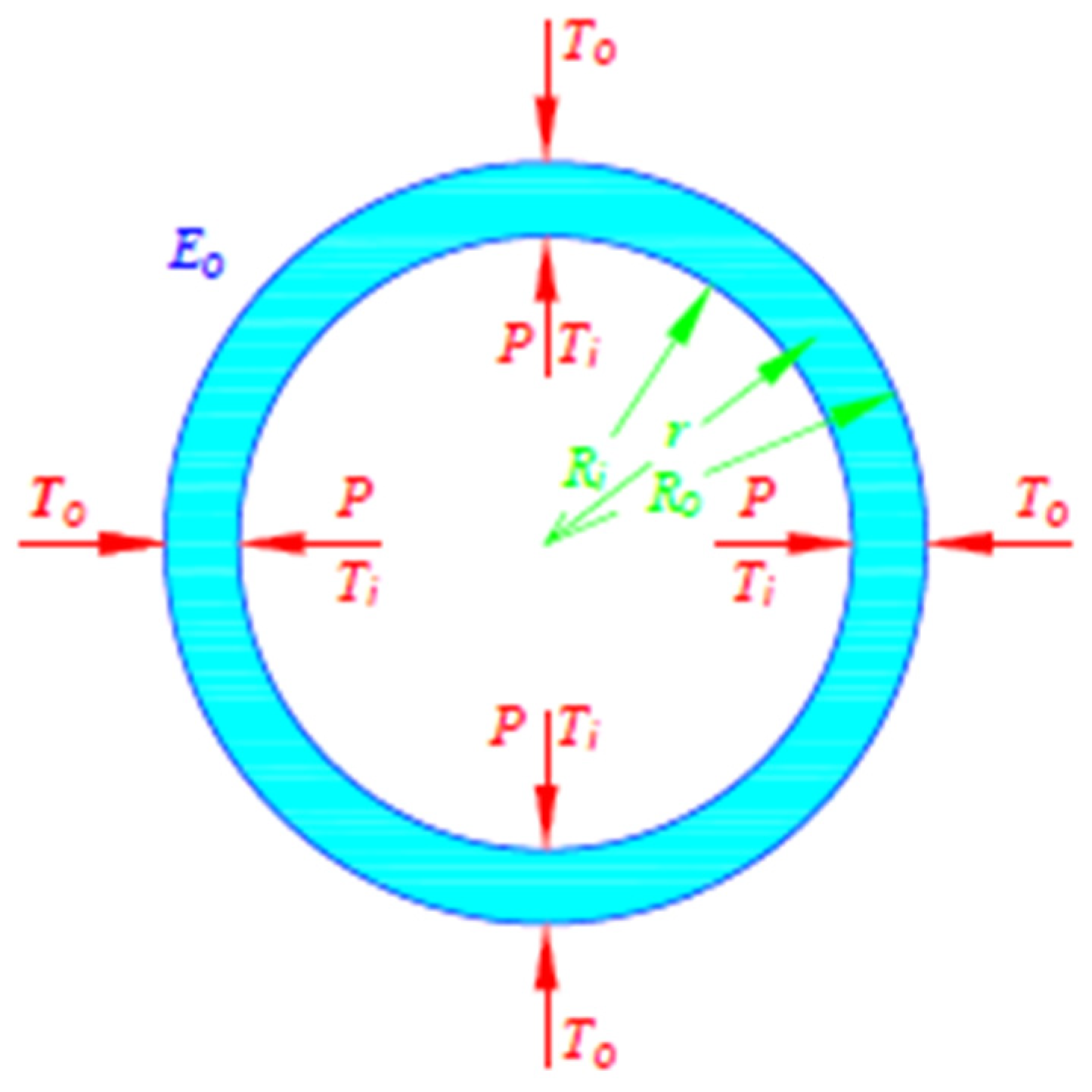
2.1.3. The Analytical Model
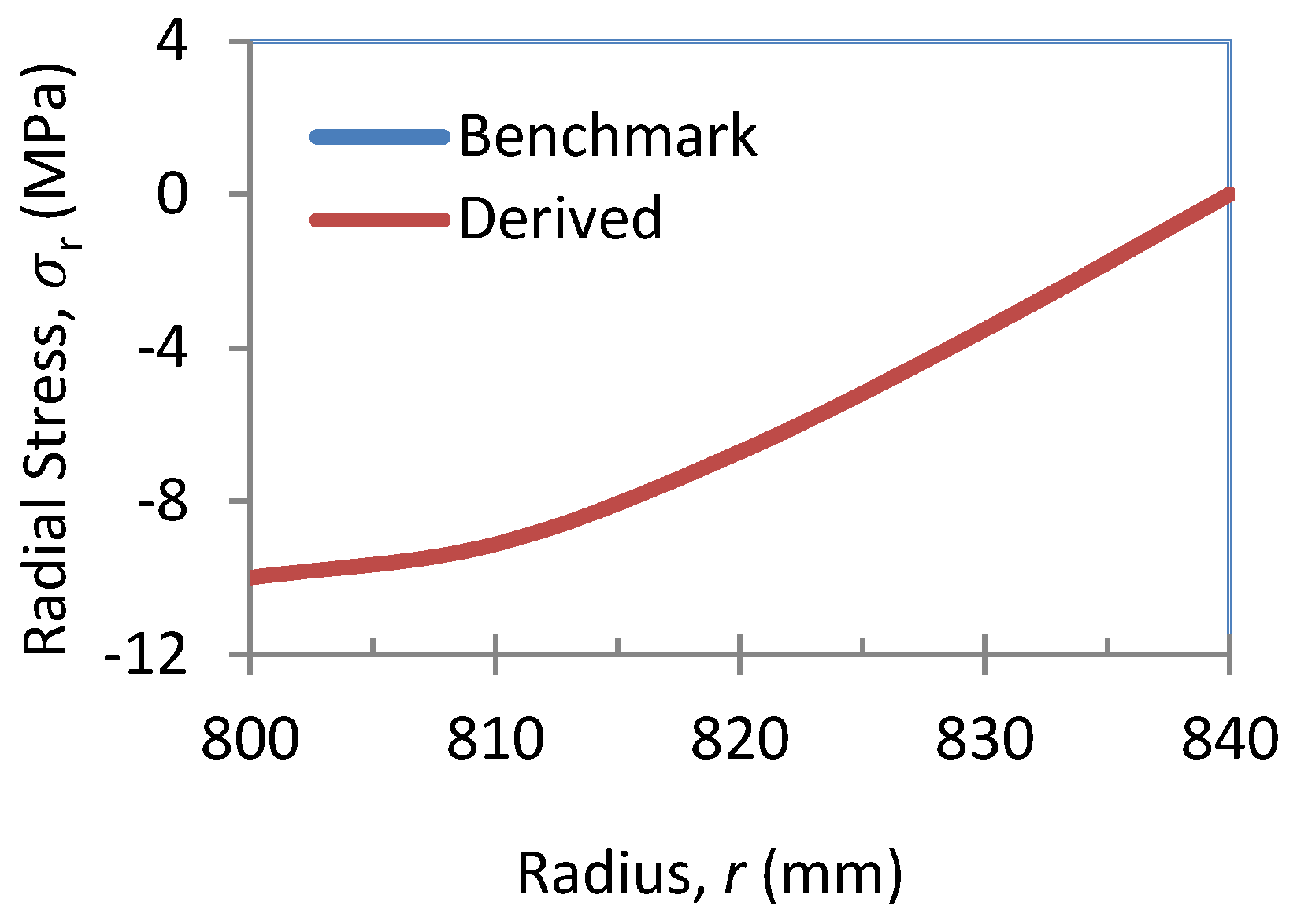
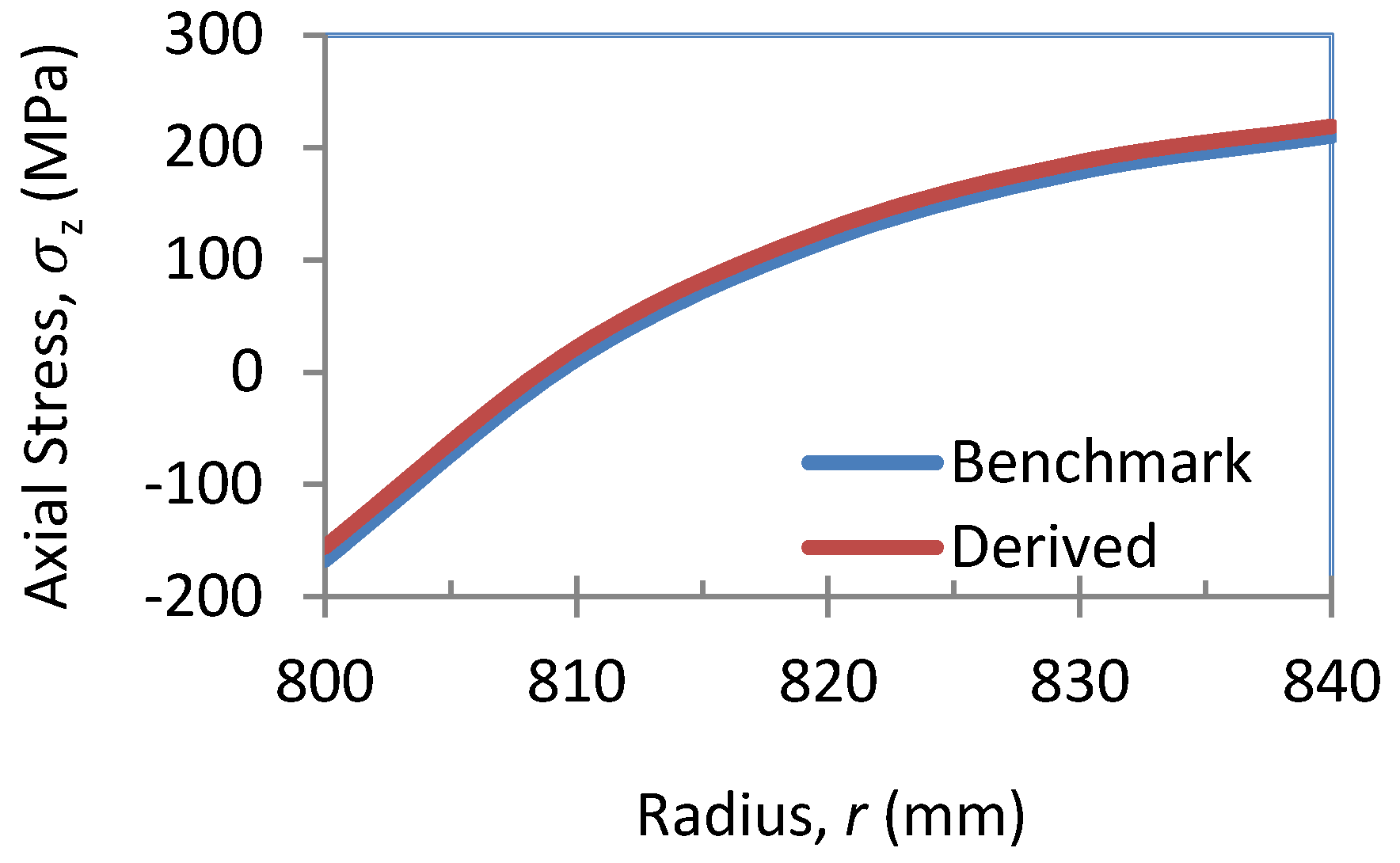
2.1.4. Outcomes
2.2. Analytical Solution for an Exponentially-Graded FG Vessel
2.2.1. Derivation of the Analytical Solution
- Mechanical equations and axial strain equationsThe mechanical stresses and axial strain equations can be written as follows:where, , , and are constants.are functions of r used for simplification of stress equations.
- Thermal equations and axial strain equationsThe Thermal stresses and axial strain equations can be written as follows:where , , and are constants.are functions of r used for the simplification of the stress equations.
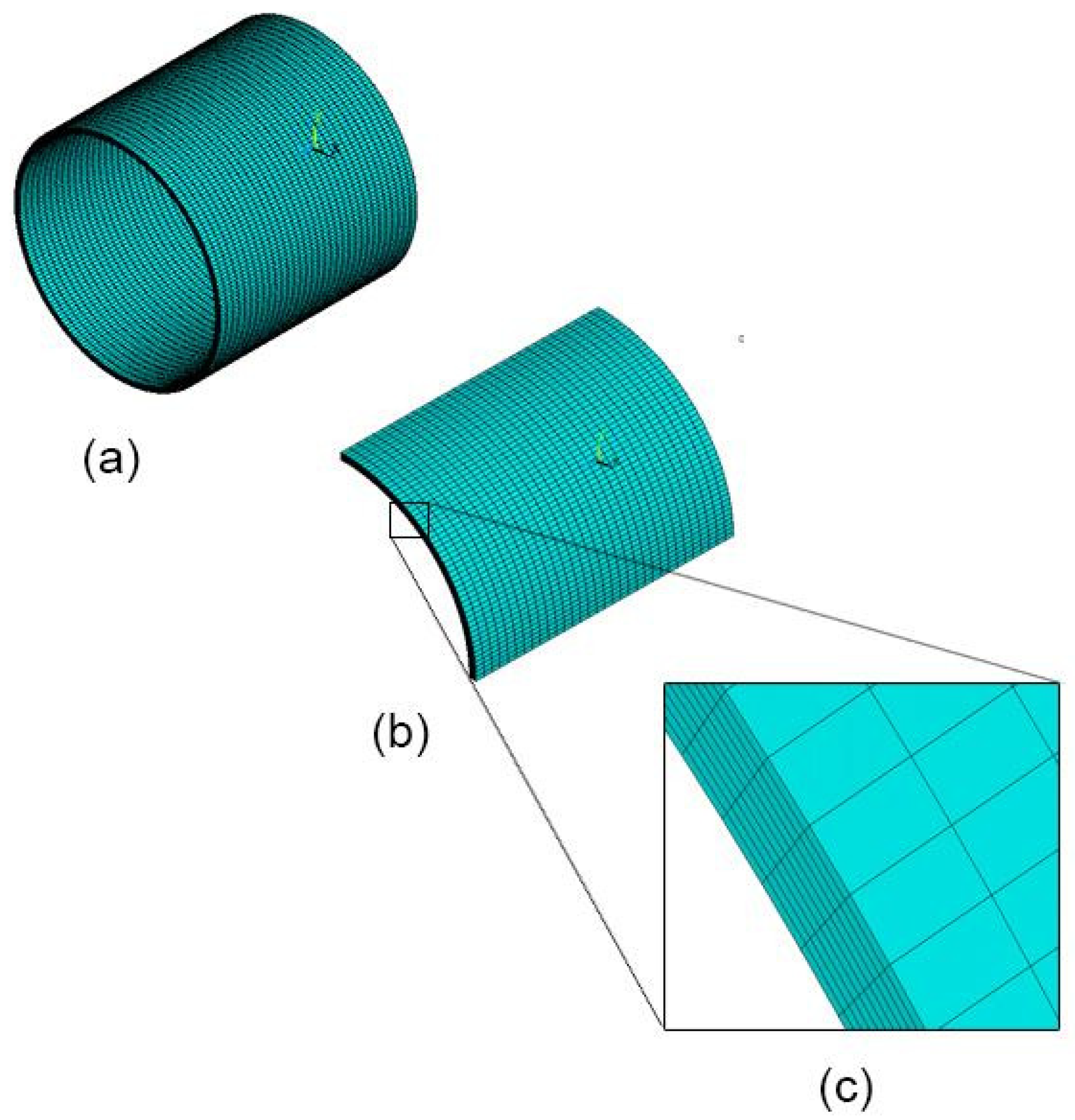
2.2.2. FE Modelling
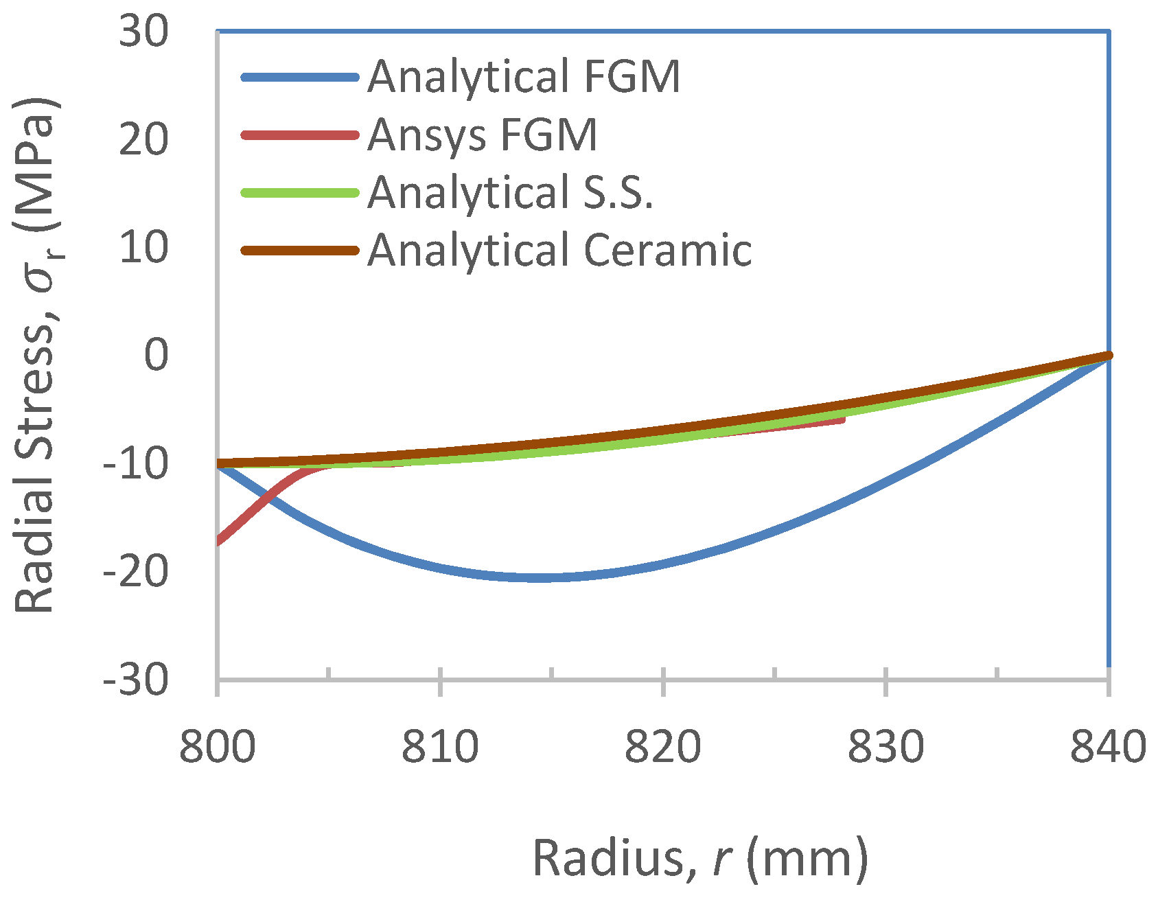
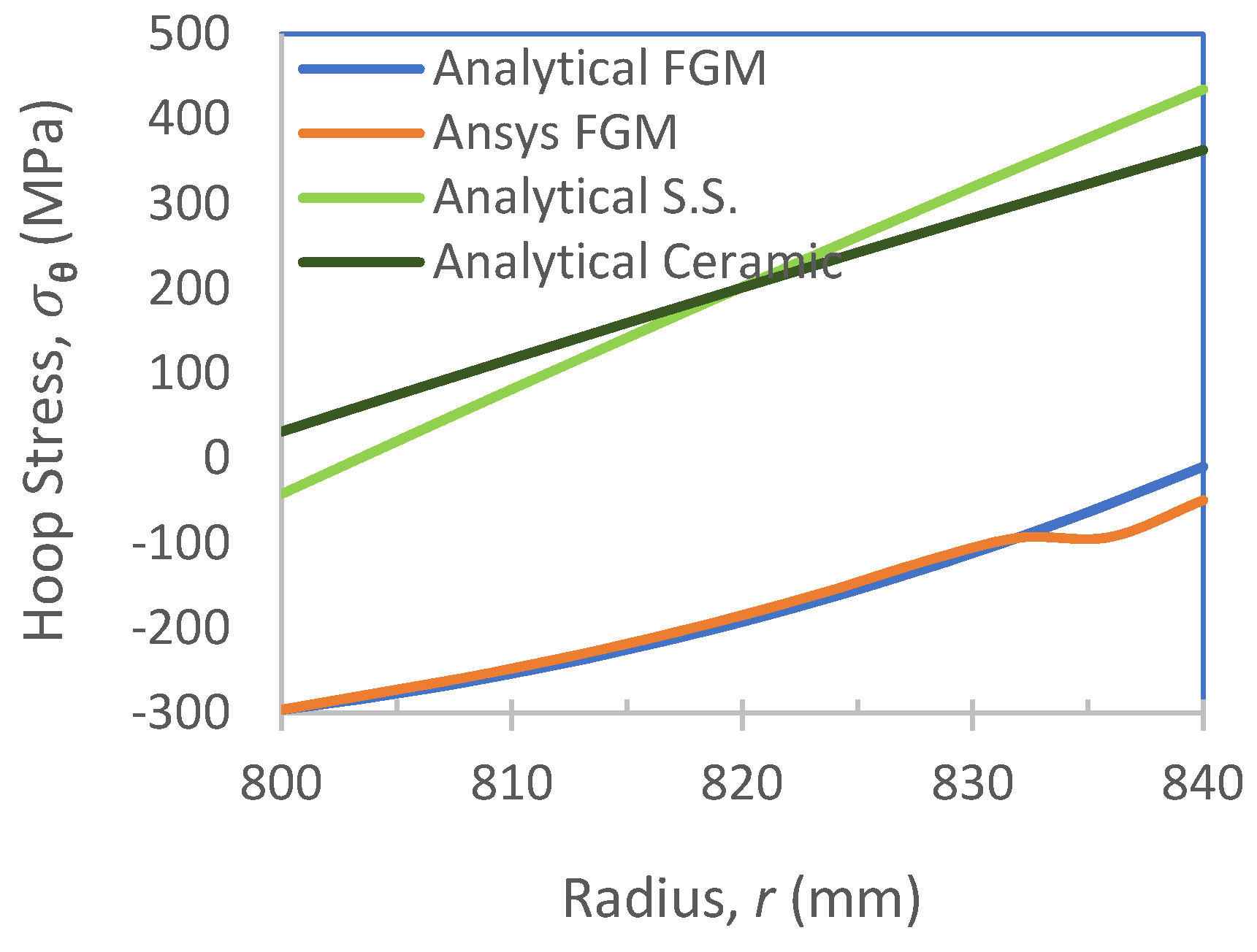
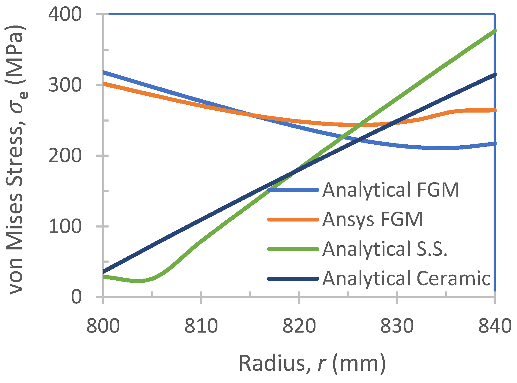
2.2.3. Results
3. Conclusions
Author Contributions
Funding
Conflicts of Interest
References
- Rasheedat, M.M.; Esther, T.A. Functionally Graded Materials; Carlos, P.A., Bergmann, P., Eds.; Springer International Publishing: Cham, Switzerland, 2017. [Google Scholar]
- Bayat, Y.; Ghannad, M.; Torabi, H. Analytical and numerical analysis for the FGM thick sphere under combined pressure and temperature loading. Arch. Appl. Mech. 2012, 82, 229–242. [Google Scholar] [CrossRef]
- Carrera, E.; Brischetto, S.; Robaldo, A. Variable Kinematic Model for the Analysis of Functionally Graded Material plates. AIAA J. 2008, 46, 194–203. [Google Scholar] [CrossRef]
- El-Megharbel, A. A Theoretical Analysis of Functionally Graded Beam under Thermal Loading. World J. Eng. Technol. 2016, 4, 437–449. [Google Scholar] [CrossRef]
- Cinefra, M.; Carrera, E.; Brischetto, S.; Belouettar, S. Thermo-mechanical analysis of functionally graded shells. J. Therm. Stress. 2010, 33, 942–963. [Google Scholar] [CrossRef]
- Nejad, M.Z.; Kashkoli, M.D. Time-dependent thermo-creep analysis of rotating FGM thick-walled cylindrical pressure vessels under heat flux. Int. J. Eng. Sci. 2014, 82, 222–237. [Google Scholar] [CrossRef]
- You, L.H.; Zhang, J.J.; You, X.Y. Elastic analysis of internally pressurized thick-walled spherical pressure vessels of functionally graded materials. Int. J. Press. Vessels Pip. 2005, 82, 347–354. [Google Scholar] [CrossRef]
- Kordkheili, S.A.H.; Naghdabadi, R. Thermoelastic analysis of a functionally graded rotating disk. Compos. Struct. 2007, 79, 508–516. [Google Scholar] [CrossRef]
- Srividhya, S.; Raghu, P.; Rajagopal, A.; Reddy, J. Nonlocal nonlinear analysis of functionally graded plates using third-order shear deformation theory. Int. J. Eng. Sci. 2018, 125, 1–22. [Google Scholar] [CrossRef]
- Čanađija, M.; Barretta, R.; de Sciarra, F.M. On Functionally Graded Timoshenko Nonisothermal Nanobeams. Compos. Struct. 2016, 135, 286–296. [Google Scholar] [CrossRef]
- Čanađija, M.; Barretta, R.; de Sciarra, F.M. A gradient elasticity model of BernoullieEuler nanobeams in non-isothermal environments. Eur. J. Mech. A Solids 2016, 55, 243–255. [Google Scholar] [CrossRef]
- De Sciarra, F.M.; Salerno, M. On thermodynamic functions in thermoelasticity without energy dissipation. Eur. J. Mech. A Solids 2014, 46, 84–95. [Google Scholar] [CrossRef]
- Barretta, R.; Canađija, M.; Luciano, R.; de Sciarra, F.M. Stress-driven modeling of nonlocal thermoelastic behavior of nanobeams. Int. J. Eng. Sci. 2018, 126, 53–67. [Google Scholar] [CrossRef]
- Gharibi, M.; Nejad, M.Z.; Hadi, A. Elastic analysis of functionally graded rotating thick cylindrical pressure vessels with exponentially-varying properties using power series method of Frobenius. J. Comput. Appl. Mech. 2017, 48, 89–98. [Google Scholar]
- Sharma, S.; Yadav, S.; Sharma, R. Thermal creep analysis of functionally graded thick- walled cylinder subjected to torsion and internal and external pressure. J. Solid Mech. 2017, 9, 302–318. [Google Scholar]
- Safari, A.; Tahani, M.; Hosseini, S.M. Two-dimensional dynamic analysis of thermal stresses in a finite-length FG thick hollow cylinder subjected to thermal shock loading using an analytical method. Acta Mech. 2011, 220, 299–314. [Google Scholar] [CrossRef]
- Shariyat, M. A nonlinear Hermitian transfinite element method for transient behavior analysis of hollow functionally graded cylinders with temperature-dependent materials under thermo-mechanical loads. Int. J. Press. Vessels Pip. 2009, 86, 280–289. [Google Scholar] [CrossRef]
- Peng, X.L.; Li, X.F. Thermoelastic analysis of a cylindrical vessel of functionally graded materials. Int. J. Press. Vessels Pip. 2010, 87, 203–210. [Google Scholar] [CrossRef]
- Tutuncu, N. Stresses in thick-walled FGM cylinders with exponentially-varying properties. Eng. Struct. 2007, 29, 2032–2035. [Google Scholar] [CrossRef]
- Wang, Z.W.; Zhang, Q.; Xia, L.Z.; Wu, J.T.; Liu, P.Q. Stress Analysis and Parameter Optimization of an FGM Pressure Vessel Subjected to Thermo-Mechanical Loadings. Procedia Eng. 2015, 130, 374–389. [Google Scholar] [CrossRef]
- Alikarami, S; Parvizi, A. Elasto-plastic analysis and finite element simulation of thick-walled functionally graded cylinder subjected to combined pressure and thermal loading. Sci. Eng. Compos. Mater. 2017, 24, 609–620. [Google Scholar] [CrossRef]
- El-Hadek, M.A. Numerical Simulation of the Inertia Friction Welding Process of Dissimilar Materials. Metall. Mater. Trans. B 2014, 45, 2346–2356. [Google Scholar] [CrossRef]
- El-Hadek, M.A. Dynamic equivalence of ultrasonic stress wave propagation in solids. Ultrasonics 2018, 83, 214–221. [Google Scholar] [CrossRef] [PubMed]


© 2018 by the authors. Licensee MDPI, Basel, Switzerland. This article is an open access article distributed under the terms and conditions of the Creative Commons Attribution (CC BY) license (http://creativecommons.org/licenses/by/4.0/).
Share and Cite
Habib, E.-S.; El-Hadek, M.A.; El-Megharbel, A. Stress Analysis for Cylinder Made of FGM and Subjected to Thermo-Mechanical Loadings. Metals 2019, 9, 4. https://doi.org/10.3390/met9010004
Habib E-S, El-Hadek MA, El-Megharbel A. Stress Analysis for Cylinder Made of FGM and Subjected to Thermo-Mechanical Loadings. Metals. 2019; 9(1):4. https://doi.org/10.3390/met9010004
Chicago/Turabian StyleHabib, El-Sayed, Medhat Awad El-Hadek, and Abla El-Megharbel. 2019. "Stress Analysis for Cylinder Made of FGM and Subjected to Thermo-Mechanical Loadings" Metals 9, no. 1: 4. https://doi.org/10.3390/met9010004
APA StyleHabib, E.-S., El-Hadek, M. A., & El-Megharbel, A. (2019). Stress Analysis for Cylinder Made of FGM and Subjected to Thermo-Mechanical Loadings. Metals, 9(1), 4. https://doi.org/10.3390/met9010004