Synthesis of Intermetallics in Fe-Al-Si System by Mechanical Alloying


Abstract
1. Introduction
- A high ball-to-powder ratio (50:1−70:1) in combination with the use of large balls (20 mm in diameter) transfers very high kinetic energy to the powder even when moderate rotational velocity (400–600 rpm) is applied.
- The use of any lubricant lowers the friction forces and temperature of the powder correspondingly. The reactions, which lead to the formation of intermetallics from elemental metals, are thermally activated in all cases. It implies that the use of any lubricant has to be avoided in ultra-high energy mechanical alloying, as was proved in reference [19].
2. Materials and Methods
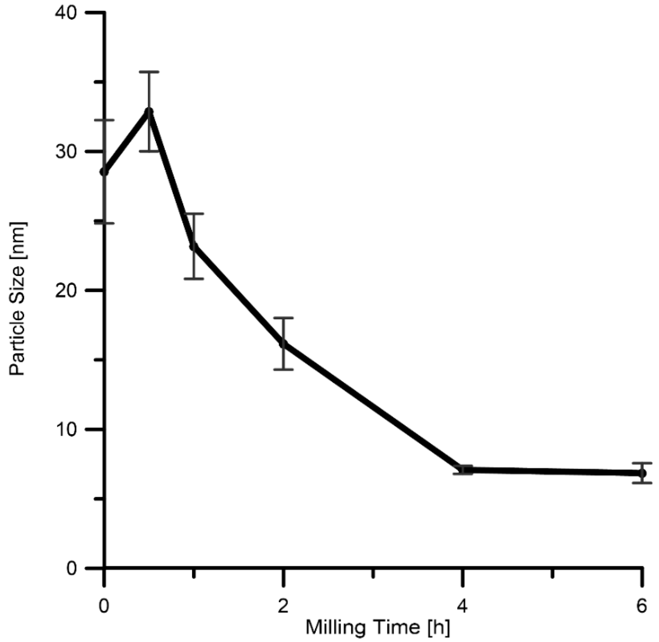
- duration: 0.5–6 h,
- each 30 min change of rotation direction,
- rotational velocity: 400 min−1,
- atmosphere: argon (purity of 99.996%)
- powder batch: 5 g
- ball-to-powder weight ratio: 60:1.
3. Results and Discussion
4. Conclusions
Author Contributions
Funding
Acknowledgments
Conflicts of Interest
References
- McKamey, C.G.; DeVan, J.H.; Tortorelli, P.F.; Sikka, V.K. A review of recent developments in Fe3Al-based alloys. J. Mater. Res. 2011, 6, 1779–1805. [Google Scholar] [CrossRef]
- Stoloff, N.S. Iron aluminides: Present status and future prospects. Mater. Sci. Eng. A 1998, 258, 1–14. [Google Scholar] [CrossRef]
- Talischi, L.A.; Samadi, A. Structural characterization and ordering transformation of mechanically alloyed nanocrystalline Fe-28Al powder. J. Ultrafine Grained Nanostruct. Mater. 2016, 49, 112–119. [Google Scholar]
- Novák, P.; Kříž, J.; Michalcová, A.; Vojtěch, D. Microstructure evolution of Fe-Al-Si and Ti-Al-Si alloys during high-temperature oxidation. Mater. Sci. Forum 2014, 782, 353–358. [Google Scholar] [CrossRef]
- Couperthwaite, R.A.; Cornish, L.A.; Mwamba, I.A.; Papo, M.J. Effect of processing route on the microstructure and properties of an Fe-Al alloy with additions of precious metal. Mater. Today Proc. 2015, 2, 3932–3942. [Google Scholar] [CrossRef]
- Deevi, S.C.; Sikka, V.K.; Liu, C.T. Processing, properties, and applications of nickel and iron aluminides. Prog. Mater. Sci. 1997, 42, 177–192. [Google Scholar] [CrossRef]
- Marker, M.C.J.; Skolyszewska-Kühberger, B.; Effenberger, H.S.; Schmetterer, C.; Richter, K.W. Phase equilibria and structural investigations in the system Al–Fe–Si. Intermetallics 2011, 19, 1919–1929. [Google Scholar] [CrossRef]
- Školáková, A.; Novák, P.; Vojtěch, D.; Kubatík, T.F. Microstructure and mechanical properties of Al–Si–Fe–X. alloys. Mater. Des. 2016, 107, 491–502. [Google Scholar] [CrossRef]
- Li, H.; Zhang, J.; Young, D.J. Oxidation of Fe–Si, Fe–Al and Fe–Si–Al alloys in Co2–H2O gas at 800 °C. Corros. Sci. 2012, 54, 127–138. [Google Scholar] [CrossRef]
- Novák, P.; Zelinková, M.; Šerák, J.; Michalcová, A.; Novák, M.; Vojtěch, D. Oxidation resistance of SHS Fe–Al–Si alloys at 800 °C in air. Intermetallics 2011, 19, 1306–1312. [Google Scholar] [CrossRef]
- Shen, C.; Pan, Z.; Cuiuri, D.; Ding, D.; Li, H. Influences of deposition current and interpass temperature to the Fe3Al-based iron aluminide fabricated using wire-arc additive manufacturing process. Int. J. Adv. Manuf. Technol. 2017, 88, 2009–2018. [Google Scholar] [CrossRef]
- Satya Prasad, V.V.; Khaple, S.; Baligidad, R.G. Melting, processing, and properties of disordered Fe-Al and Fe-Al-C based alloys. J. Miner. Met. Mater. Soc. 2014, 66, 1785–1793. [Google Scholar] [CrossRef]
- Sundar, R.S.; Baligidad, R.G.; Prasad, Y.V.R.K.; Sastry, D.H. Processing of iron aluminides. Mater. Sci. Eng. A 1998, 258, 219–228. [Google Scholar] [CrossRef]
- Song, H.; Wu, Y.; Tang, C.; Yuan, S.; Gong, Q.; Liang, J. Microstructure and mechanical properties of FeAl intermetallics prepared by mechanical alloying and hot-pressing. Tsinghua Sci. Technol. 2009, 14, 300–306. [Google Scholar] [CrossRef]
- Krasnowski, M.; Kulik, T. Nanocrystalline FeAl intermetallic produced by mechanical alloying followed by hot-pressing consolidation. Intermetallics 2007, 15, 201–205. [Google Scholar] [CrossRef]
- Novák, P.; Moravec, H.; Vojtěch, V.; Kopeček, J. Powder-metallurgy preparation of Ni-Ti shape-memory alloy using mechanical alloying and spark plasma sintering. Mater. Technol. 2017, 51, 141–144. [Google Scholar]
- Suryanarayana, C. Mechanical alloying and milling. Prog. Mater. Sci. 2001, 46, 1–184. [Google Scholar] [CrossRef]
- Enayati, M.H.; Mohamed, F.A. Application of mechanical alloying/milling for synthesis of nanocrystalline and amorphous materials. Int. Mater. Rev. 2014, 59, 394–416. [Google Scholar] [CrossRef]
- Novák, P.; Průša, F.; Nová, K.; Bernatiková, A.; Salvetr, P.; Kopeček, J.; Haušild, P. Application of mechanical alloying in synthesis of intermetallics. Acta Phys. Pol. A 2018, 134, 720–723. [Google Scholar] [CrossRef]
- Shi, H.; Guo, D.; Ouyang, Y. Structural evolution of mechanically alloyed nanocrystalline FeAl intermetallics. J. Alloys Compd. 2008, 455, 207–209. [Google Scholar] [CrossRef]
- Krasnowski, M.; Grabias, A.; Kulik, T. Phase transformations during mechanical alloying of Fe–50% Al and subsequent heating of the milling product. J. Alloys Compd. 2006, 424, 119–127. [Google Scholar] [CrossRef]
- Haghighi, S.E.; Janghorban, K.; Izadi, S. Structural evolution of Fe–50 at % Al powders during mechanical alloying and subsequent annealing processes. J. Alloys Compd. 2010, 495, 260–264. [Google Scholar] [CrossRef]
- Enayati, M.H.; Salehi, M. Formation mechanism of Fe3Al and FeAl intermetallic compounds during mechanical alloying. J. Mater. Sci. 2005, 40, 3933–3938. [Google Scholar] [CrossRef]
- Zoz, H.; Reichardt, R.; Ren, H. Energy balance during mechanical alloying, measurement and calculation method supported by the Maltoz®-software. Adv. Powder Metall. Part. Mater. 1999, 1, 1–109. [Google Scholar]
- Abdellaoui, M.; Gaffet, E. The physics of mechanical alloying in a planetary ball mill: Mathematical treatment. Acta Metall. Mater. 1995, 43, 1087–1098. [Google Scholar] [CrossRef]
- Shelekhov, E.V.; Tcherdyntsev, V.V.; Pustov, L.Y.; Kaloshkin, S.D.; Tomilin, I.A. Calculation of energy intensity and temperature of mechanoactivation process in planetary ball mill by computer simulation. In Investigations and Applications of Severe Plastic Deformation; Lowe, T.C., Valiev, R.Z., Eds.; Springer Netherlands: Dordrecht, The Netherlands, 2000; pp. 139–145. [Google Scholar]
- Prică, C.-V.; Marinca, T.F.; Popa, F.; Sechel, N.A.; Isnard, O.; Chicinaş, I. Synthesis of nanocrystalline Ni3Fe powder by mechanical alloying using an extreme friction mode. Adv. Powder Technol. 2016, 27, 395–402. [Google Scholar] [CrossRef]
- Bernatiková, A.; Novák, P.; Průša, F. Preparation of Ti-Al and Fe-Al alloys by mechanical alloying. Acta Phys. Pol. A 2018, 134, 733–737. [Google Scholar] [CrossRef]
- Novák, P.; Michalcová, A.; Marek, I.; Mudrová, M.; Saksl, K.; Bednarčík, J.; Zikmund, P.; Vojtěch, D. On the formation of intermetallics in Fe–Al system-an in situ XRD study. Intermetallics 2013, 32, 127–136. [Google Scholar] [CrossRef]
- Song, J.L.; Lin, S.B.; Yang, C.L.; Ma, G.C.; Liu, H. Spreading behavior and microstructure characteristics of dissimilar metals TIG welding-brazing of aluminum alloy to stainless steel. Mater. Sci. Eng. A 2009, 509, 31–40. [Google Scholar] [CrossRef]
- Jóźwiak, S.; Karczewski, K.; Bojar, Z. Kinetics of reactions in FeAl synthesis studied by the DTA technique and JMA model. Intermetallics 2010, 18, 1332–1337. [Google Scholar] [CrossRef]
- Liu, Z.-K.; Chang, Y.A. Thermodynamic assessment of the Al-Fe-Si system. Metall. Mater. Trans. A 1999, 30, 1081–1095. [Google Scholar] [CrossRef]
- Effenberg, G. Ternary Alloy Systems-Phase Diagrams, Crystallographic and Thermodynamic Data: Light Metal Systems, Part 2: Selected Systems From Al-Cu-Fe to Al-Fe-Ti; Landolt-Börnstein: Stuttgart, Germany, 2005. [Google Scholar]
- Huang, B.L.; Perez, R.J.; Lavernia, E.J.; Luton, M.J. Formation of supersaturated solid solutions by mechanical alloying. Nanostruct. Mater. 1996, 7, 67–79. [Google Scholar] [CrossRef]
- Kabekkodu, S. ICCD 2018 Powder Diffraction File; International Centre for Diffraction Data: 12 Campus Boulevard, Newton Square, PA, USA.
- Kang, H.Z.; Hu, C.T. Swelling behavior in reactive sintering of Fe-Al mixtures. Mater. Chem. Phys. 2004, 88, 264–272. [Google Scholar] [CrossRef]


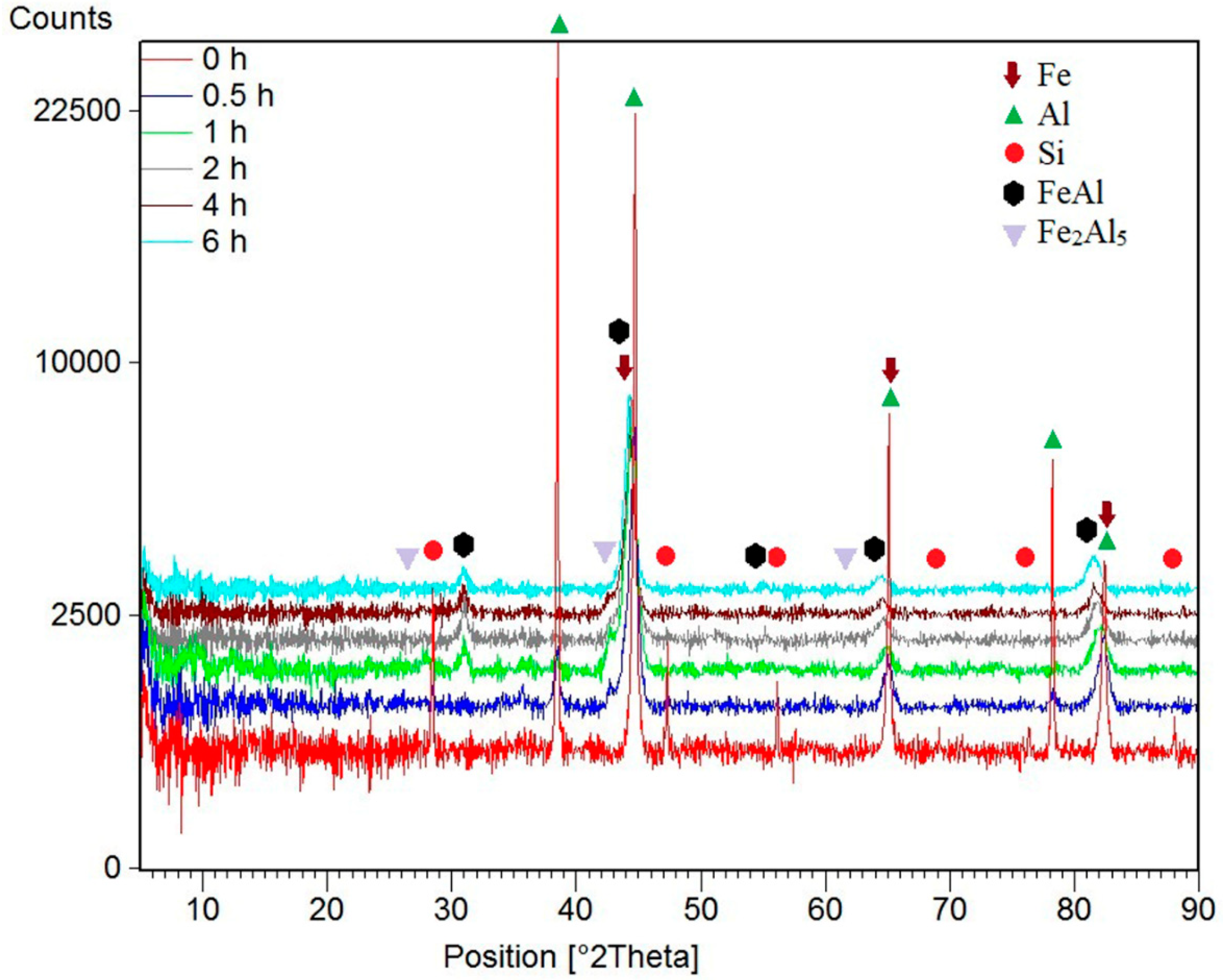
| Milling Time (h) | Weight Percentage (%) | |||||
|---|---|---|---|---|---|---|
| Fe | Al | Si | FeAl | Fe2Al5 | ||
| Before MA | 60 | 35 | 5 | 0 | 0 | |
| 0.5 | 55 | 31 | 5 | 0 | 9 | |
| 1 | 0 | 5 | 1 | 82 | 12 | |
| 2 | 0 | 0 | 0 | 94 | 6 | |
| 4 | 0 | 0 | 0 | 96 | 4 | |
| 6 | 0 | 0 | 0 | 100 | 0 | |
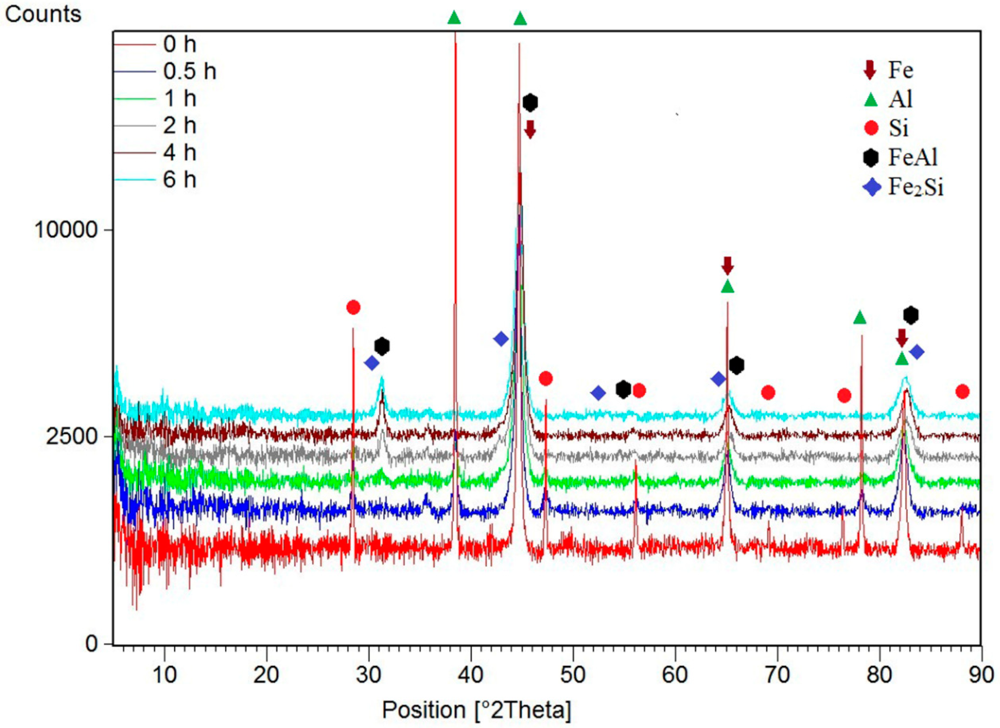
| Milling Time (h) | Weight Percentage (%) | |||||
|---|---|---|---|---|---|---|
| Fe | Al | Si | FeAl | Fe2Si | ||
| Before MA | 60 | 30 | 10 | 0 | 0 | |
| 0.5 | 55 | 30 | 6 | 0 | 9 | |
| 1 | 0 | 12 | 9 | 74 | 5 | |
| 2 | 0 | 5 | 4 | 87 | 4 | |
| 4 | 0 | 0 | 0 | 100 | 0 | |
| 6 | 0 | 0 | 0 | 100 | 0 | |
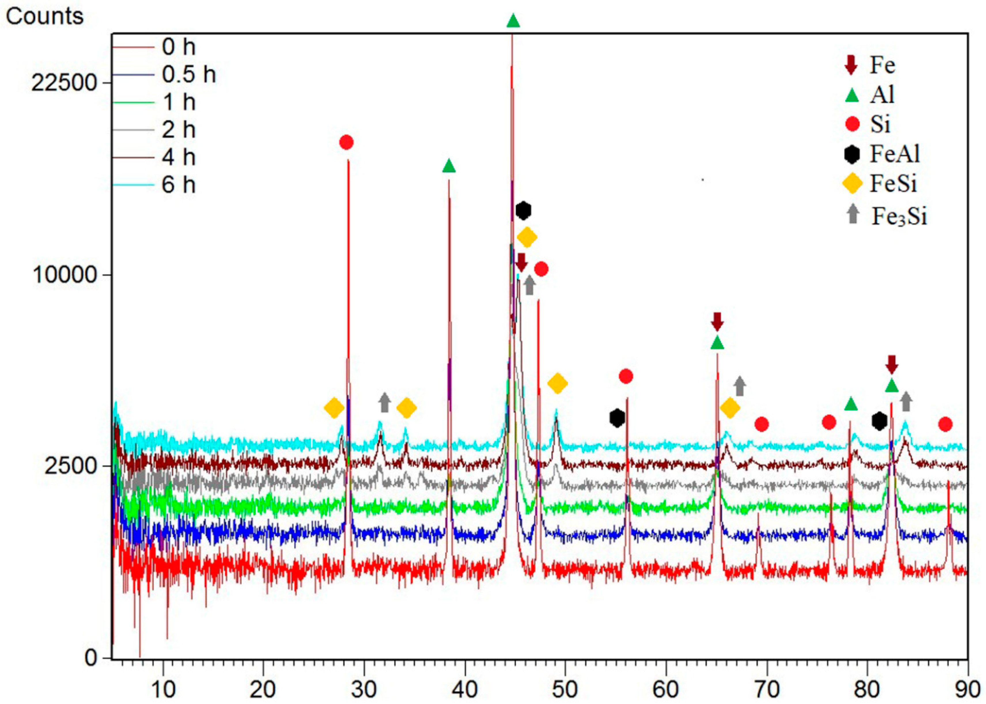
| Milling Time (h) | Weight Percentage (%) | ||||||
|---|---|---|---|---|---|---|---|
| Fe | Al | Si | FeAl | Fe3Si | FeSi | ||
| Before MA | 60 | 20 | 20 | 0 | 0 | 0 | |
| 0.5 | 60 | 20 | 20 | 0 | 0 | 0 | |
| 1 | 75 | 4 | 21 | 0 | 5 | 0 | |
| 2 | 14 | 0 | 3 | 41 | 22 | 20 | |
| 4 | 0 | 0 | 0 | 27 | 46 | 27 | |
| 6 | 0 | 0 | 0 | 27 | 46 | 27 | |
| Milling Time (h) | FeAl | Fe3Si | |
|---|---|---|---|
| FeAl35Si5 | FeAl30Si10 | FeAl20Si20 | |
| Ref [35] | 2.899 | 2.899 | 5.662 |
| 1 | 2.886 ± 0.001 | 3.095 ± 0.001 | - |
| 2 | 2.879 ± 0.001 | 2.854 ± 0.001 | 5.671 ± 0.001 |
| 4 | 2.885 ± 0.001 | 2.859 ± 0.001 | 5.648 ± 0.001 |
| 6 | 2.888 ± 0.001 | 2.869 ± 0.001 | 5.663 ± 0.001 |
| Powder Mixture | Milling Duration (h) | Identified Phase | Weight Percentage (%) | ||
|---|---|---|---|---|---|
| Fe | Al | Si | |||
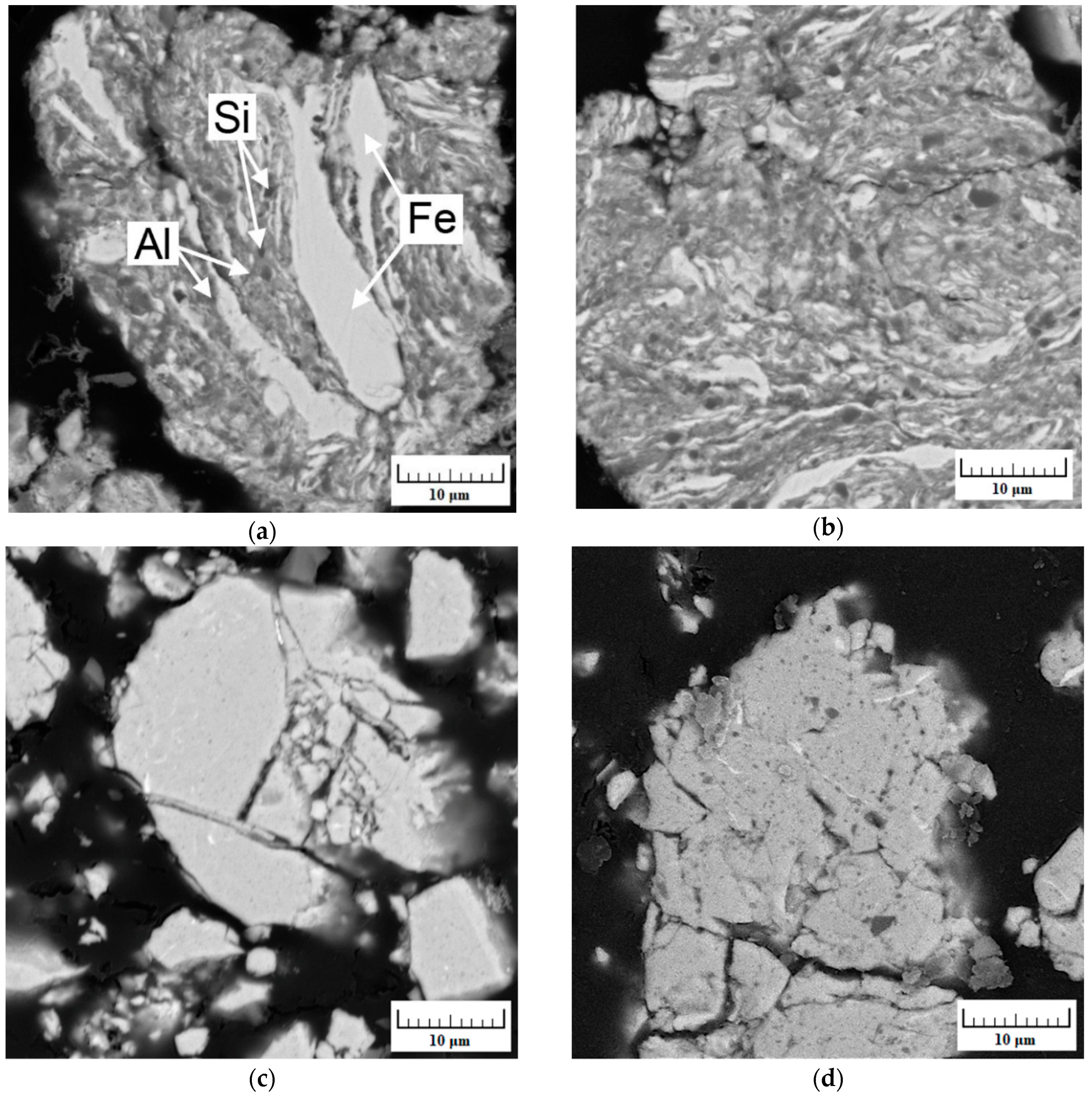
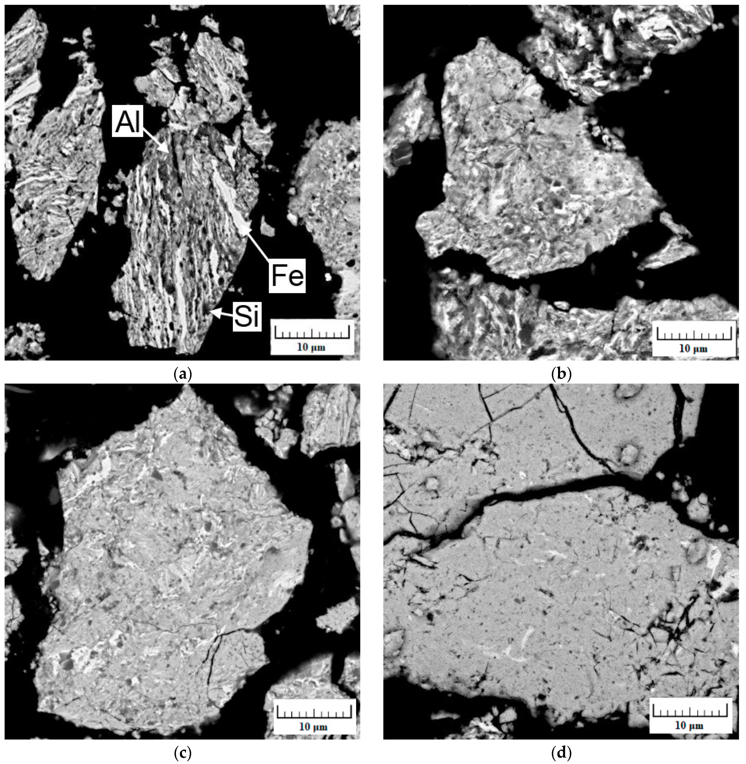
| FeAl30Si10 | 0.5 | Fe | 87.7 ± 1.6 | 9.8 ± 0.8 | 2.5 ± 0.8 |
| FeAl30Si10 | 0.5 | Al | 15.6 ± 1.8 | 67.1 ± 3.5 | 17.3 ± 1.7 |
| FeAl30Si10 | 0.5 | Si | 4.1 ± 1.2 | 0 | 95.9 ± 1.2 |
| FeAl20Si20 | 0.5 | Fe | 87.0 ± 1.0 | 10.0 ± 0.5 | 3.0 ± 0.5 |
| FeAl20Si20 | 0.5 | Al | 6.7 ± 1.0 | 69.4 ± 2.0 | 23.9 ± 1.0 |
| FeAl20Si20 | 0.5 | Si | 17.1 ± 0.5 | 18.5 ± 0.5 | 64.3 ± 1.0 |
| Annealing Temperature (°C) | Alloy Composition | Weight Percentage (%) | ||||
|---|---|---|---|---|---|---|
| FeAl | Fe3Si | Fe2Al5 | FeSi | Fe2Al3Si3 | ||
| 630 °C | FeAl35Si5 | 91 | - | 9 | - | - |
| 630 °C | FeAl30Si10 | 95 | - | 5 | - | - |
| 630 °C | FeAl20Si20 | 25 | 44 | 4 | 27 | - |
| 1030 °C | FeAl35Si5 | 86 | 5 | 9 | - | - |
| 1030 °C | FeAl30Si10 | 90 | 8 | 5 | - | - |
| 1030 °C | FeAl20Si20 | 25 | 45 | 0 | 20 | 10 |
© 2018 by the authors. Licensee MDPI, Basel, Switzerland. This article is an open access article distributed under the terms and conditions of the Creative Commons Attribution (CC BY) license (http://creativecommons.org/licenses/by/4.0/).
Share and Cite
Nová, K.; Novák, P.; Průša, F.; Kopeček, J.; Čech, J. Synthesis of Intermetallics in Fe-Al-Si System by Mechanical Alloying. Metals 2019, 9, 20. https://doi.org/10.3390/met9010020
Nová K, Novák P, Průša F, Kopeček J, Čech J. Synthesis of Intermetallics in Fe-Al-Si System by Mechanical Alloying. Metals. 2019; 9(1):20. https://doi.org/10.3390/met9010020
Chicago/Turabian StyleNová, Kateřina, Pavel Novák, Filip Průša, Jaromír Kopeček, and Jaroslav Čech. 2019. "Synthesis of Intermetallics in Fe-Al-Si System by Mechanical Alloying" Metals 9, no. 1: 20. https://doi.org/10.3390/met9010020
APA StyleNová, K., Novák, P., Průša, F., Kopeček, J., & Čech, J. (2019). Synthesis of Intermetallics in Fe-Al-Si System by Mechanical Alloying. Metals, 9(1), 20. https://doi.org/10.3390/met9010020