Review

Repair and Reinforcement of Historic Timber Structures with Stainless Steel—A Review

by
Marco Corradi
1,*,
Adelaja Israel Osofero
2 and
Antonio Borri
1
1
Department of Engineering, University of Perugia, 06125 Perugia, Italy
2
School of Engineering, University of Aberdeen, Aberdeen AB24 3UE, UK
*
Author to whom correspondence should be addressed.
Metals 2019, 9(1), 106; https://doi.org/10.3390/met9010106
Submission received: 20 December 2018 / Revised: 11 January 2019 / Accepted: 17 January 2019 / Published: 21 January 2019
(This article belongs to the Special Issue Manufacturing and Application of Stainless Steels)

Abstract

:
Recent trends in the use of stainless steel profiles for repair and reinforcement of historic timber structures, after degradation due to biotic and non-biotic attacks, are discussed in this paper. These structural challenges can vary from inadequate load carrying capacity to complexities involved with choice of repair materials and techniques. Given the recurring requirements of conservation authorities in terms of reversibility of interventions and compatibility between historic and new materials, an increase in the use of non-invasive reinforcement materials and reversible techniques was observed. Subsequently, engineers and researchers have increasingly employed stainless steel alloys in retrofitting historic timber structures. This paper therefore presents the state of the art in the use of stainless steel profiles in retrofitting timber structural elements within historic structures. It includes a review of the development of the retrofitting methods and existing experimental studies on the mechanical behavior of timber structures reinforced with stainless steel. Finally, it presents a number of case studies and draws conclusions on current trends and practices based on reported studies.

1. Introduction

The use of stainless steel components, particularly in new constructions, has experienced a huge increase in recent times. Stainless steel is now widely used for both non-structural applications and as ribbed reinforcement bars for concrete, members (beams, columns, ties, etc.) in trusses, bridges and buildings. Similar to structural carbon steel, stainless steel elements can be hot rolled and fabricated or cold rolled formed. However, for many structural and civil engineers, stainless steel can be a confusing material: the term stainless steel refers to a large number of diverse alloys such as the ferritic, the austenitic and duplex stainless steels. Stainless steel often has substantially varying physical and mechanical properties [1,2,3].
It is well known that the main reason for the use of stainless steel in construction is its resistance to corrosion. However, this property can also vary from one stainless steel alloy to another. Furthermore, there are many other reasons for its application in construction industry: its intrinsic isotropy, the post-elastic plastic behavior, lightness, etc. Most of these properties are in common with carbon steel but are not with other structural materials such as composites.
The use of stainless steel in construction started during the early 20th century with the use of austenitic steel alloys. These alloys were firstly used for reinforcement and stabilization work [4]. In recent times however, there has been an encouraging trend in stainless steel usage, particularly in the construction industry. Approximately 14% of total annual consumption of stainless steel is now used in new constructions [5].
The use of stainless steel alloys for reinforcement of architectural heritage structures has further positive characteristics, making its use even more interesting than in new constructions. In this paper, the state of the art of their use for repair and reinforcement of historic timber constructions will be addressed. In addition to the cited specific strength, corrosion resistance and specific strength, stainless steel possesses other desirable characteristics, for example, its high compatibility with timber makes it suitable for reinforcing timber structures.
The conservation of architectural heritage structures is an important topic in many European countries, with many of them having a government department at national, state or local level, dedicated to this. This should be expected, considering the social, cultural and economic value of these heritage structures. Due to the nature and age of these structures (mostly pre-1920 masonry structures), repair and restoration are often required with the aim of preserving as much of the original structure as possible, i.e., minimal intervention [6,7]. It is also usually required that compatible new materials and reversible retrofitting methods are used. Conservation authorities usually want retrofitting to be done in such a way that reinforcements can be removed in the future, if necessary, without damaging the original timber structure.
The requirements discussed above, in addition to varying loading conditions the structures are often subjected to, call for innovative materials and techniques in retrofitting timber structures. However, it has been challenging to find effective solutions that will also meet the requirements for compatibility and reversibility. Engineers have to make crucial compromises in the meanwhile with ongoing research efforts focusing on the development of new materials and methods for repair and reinforcement. A good example of these efforts is the recent calls for the strategic investments in research and skills, supported by the European Commission (Horizon H2020 call) and national government funding.
One of the most common practices in retrofitting historic timber structures is the use of FRPs (Fiber Reinforced Polymers). FRPs are usually composed of thin fibers of carbon and glass and are, more often than not, epoxy-glued to the deficient timber structure. Several studies have demonstrated that it is possible to reinforce or repair timber structures using composite sheets, bars or strips [8,9,10,11,12,13,14]. However, major setbacks in the use of FRPs include their durability, poor compatibility with parent materials, degradation of fiber and poor reversibility [15,16]. These setbacks, which have led some conservation authorities to prohibit or, at least, limit the use of organic adhesives and composite materials on timber structures, is one of the reasons for increased adaptation of stainless steel in retrofitting historic timber structures.
However, there has been limited work done on stainless steel as reinforcement of pre-existing timber structures. This could be due to a number of factors: (1) High cost of stainless steel alloys, (2) Use of competitor materials (FRP) and public perception of FRPs as having excellent mechanical properties, (3) Limited availability, in the construction market, of stainless steel structural profiles.
While composite materials are typically epoxy-glued to timber structures, stainless steel is usually applied by mechanical connectors (screws, bolts, fasteners, etc.). This ensures higher long-term effectiveness of the stainless steel-timber connection compared to FRPs [17]. Other advantages of using stainless steel are reversibility, high durability, compatibility with timber. This is in line with the requirements of the ICOMOS International Wood Committee [18]. Stainless steels are also reversible and high durable. Mechanical connections are removable, and their application causes limited damage to the historic timber structure. While it is well known that high reductions of composites mechanical properties occur in the long run, stainless steel is characterized by negligible mechanical degradation. These characteristics are essentials to satisfying the requirements of conservation authorities and mechanical characteristics when stainless steel is used for repair and reinforcement of heritage timber structures. Stainless steel alloys also possess some aesthetic characteristics, such as an attractive appearance, and minor safety precaution measures are required during application compared to modern solvent-free epoxies and FRPs.
The strength analysis of the connections should always be considered when screwed or bolted connections are used for mechanically attached reinforcement. The resistance of these connections to temperature is of critical importance for timber structures. However, given the relatively low mechanical properties of timber compared to that of the steel screws/bolts, failure usually occurs in the timber material. Tightening parameters and the effects of excess torque in bolts can produce significant damage to historic timber structures, especially when they are made of softwood. Furthermore, defects (knots, shake defects, splits, high-values of grain deviation, etc.) around the area of reinforcement application on the timber structures could compromise the effectiveness of the reinforcement [19].
This study therefore aims to critically review the use of stainless steel for repair and reinforcement of civil timber historic structures. Previously adopted repair and retrofitting techniques are presented and limitations of these techniques are discussed. Finally, suggestions for possible future approaches both in terms of new stainless steel materials and repair techniques are also presented.

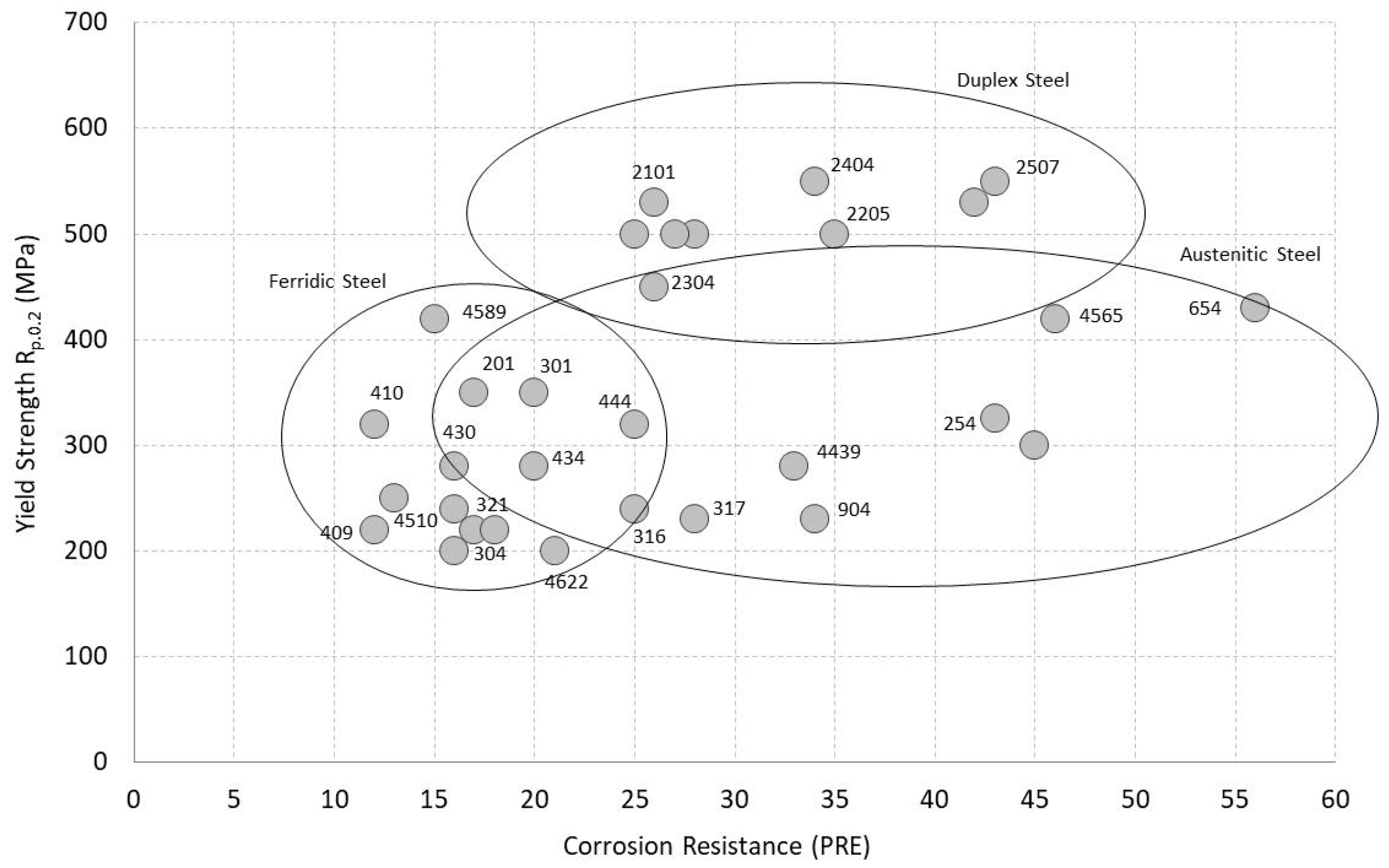
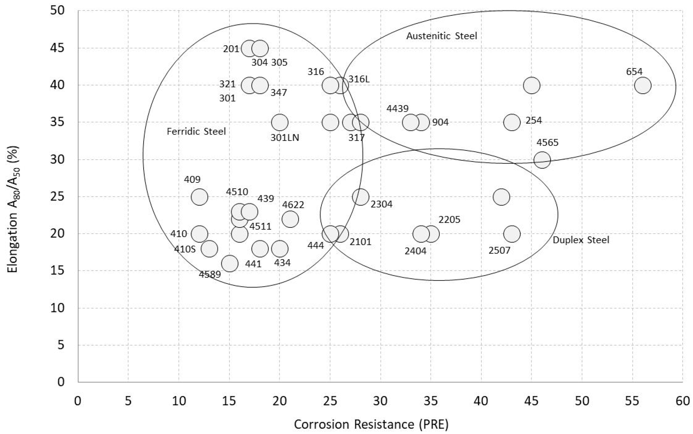
2. Stainless Typologies for Structural Applications

The major chemical constituent of Stainless steels is Fe (Iron) alloys with some Cr (Chromium) addition. Chromium acts as the main alloying element (typically between 10–20%) and results in high corrosion resistance due to surface oxidation and protection. Stainless steel corrosion resistance is about 200 times that of normal carbon steel.
Other chemical elements, such as Ni (Nichel), Mo (Molybdenum) and Ti (Titanium) are usually added for special purposes. These added chemical elements have significant effects on the microstructure evolution, mechanical behavior and the corrosion resistance of the resulting stainless steel. Corrosion resistance of stainless steel can be further improved by reducing C (Carbon) content and increasing the content of other elements of the alloy. Generally, stainless steels can be can be categorized according to their chemical compositions as shown in Table 1.
Austenitic steel is the most common type of stainless steel and is mainly used for food processing equipment, utensils for kitchens and medical equipment. This easily weldable, non-magnetic and not heat-treatable material [22,23,24] can be divided into three families: Cr-Ni (300 series), Mn-Cr-Ni-N (200 series) and specialty alloys. This family of material is non-magnetic and not heat-treatable. Ferritic steels which usually contain low Ni content, 12–17% Cr and a very low amount of C (<0.1%) could also contain other alloying elements (e.g., Mo, Al, Ti). Although Ferritic steels are known for their good ductility and formability, their behavior at high temperatures is relatively poor when compared to austenitic materials and they are also not heat treatable. For some stainless steel grades (409 and 405), ferritic stainless steels are usually cheaper than many other stainless steels [25,26,27,28].
Another type of stainless steels are the martensitic alloys characterized by 11–17% Cr, < 0.4% Ni and relatively high C content (1.2%). Martensitic stainless steels are hardenable and their formability and weldability characteristics are affected by their carbon content. This alloy often requires preheating and post-welding heat treatment to achieve desired properties. They have wide applications in knives, cutting tools, dental and surgical equipment.
Finally, duplex alloys are mainly adopted in chemical plants and piping applications and are characterized by 22–25% Cr and 5% Ni and some Mo and N addition. They have high yield strength and stress corrosion resistance in chloride when compared with austenitic stainless steels. The last type of stainless steel is from precipitation hardening. This type of stainless steel contains Cr-Ni stainless and Al, Cu and Ti as alloying elements. These alloying elements allow the material to harden in a solution and show both austenitic or martensitic microstructure in an aged condition.
Stainless steel prices vary according to their alloy type. Recent prices (Nov. 2018) are as follows: (1) Ferritic steels-1600 €/ton (EN 1.4016); (2) Austenitic steels-2350 €/ton (EN 1.4301); (3) Duplex steels-6500 €/ton (EN 1.4462). Prices will rise (>9000 €/ton) when higher Ni contents (>50%) are required in aggressive environment.
Corrosion resistance of different stainless steel grades is compared by using the Pitting Resistance Equivalent Number (PRE) calculated from Equation (1).
PRE = Cr + 3.3 × Mo
where Cr and Mo in Equation (1) are the percentages of Chromium and Molybdenum, respectively.
Stainless steels applications require optimum mechanical properties and corrosion resistance (PRE), both of which strongly depend on the steel microstructure (Figure 1 and Figure 2). The corrosion resistance of stainless steels increases with an increase in the PRE value. For example, for a stainless steel to be considered sea water resistant, it is suggested to have RPE that is greater than 32. Corrosion resistance is also critical for outdoor/unprotected applications. For example, when stainless steel profiles are used to reinforce deficient external masonry structures.
Yield stress, strain at yield and corrosion resistance all strongly depend on the type of stainless steel: low with ferritic steels and typically high with duplex steels. For example, with a reference value of 275 MPa yield strength (typical of the standard JR275 grade [30]), an elongation at failure of 40% is expected for ferritic stainless steels while about 60% extension is estimated in the case of austenitic steels. Ductility requirement for stainless steel applications varies, i.e., moderate ductility and high modulus are generally required for interventions related to confinement of timber columns or compressed members, while higher ductility is required for bending reinforcement of beams. To avoid stress concentrations, ductility is also a desirable requirement when stainless steels are used to repair rotting wood and for reinforcement interventions [31].
Cost of stainless steel also varies with alloy types as the price depends mainly on the cost of alloying elements rather than on the process cost: Ferritic is the cheapest and duplex steels the most expensive. Irrespective of the alloying material, all stainless steels have characteristic high elongation values which makes it easy to form them and thus commonly used in construction.

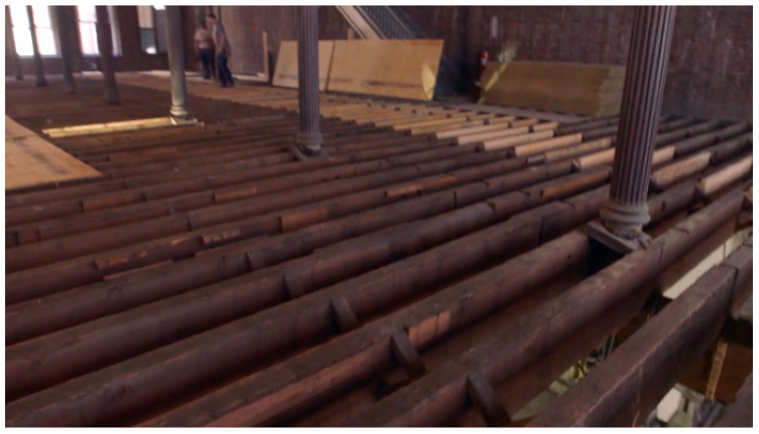
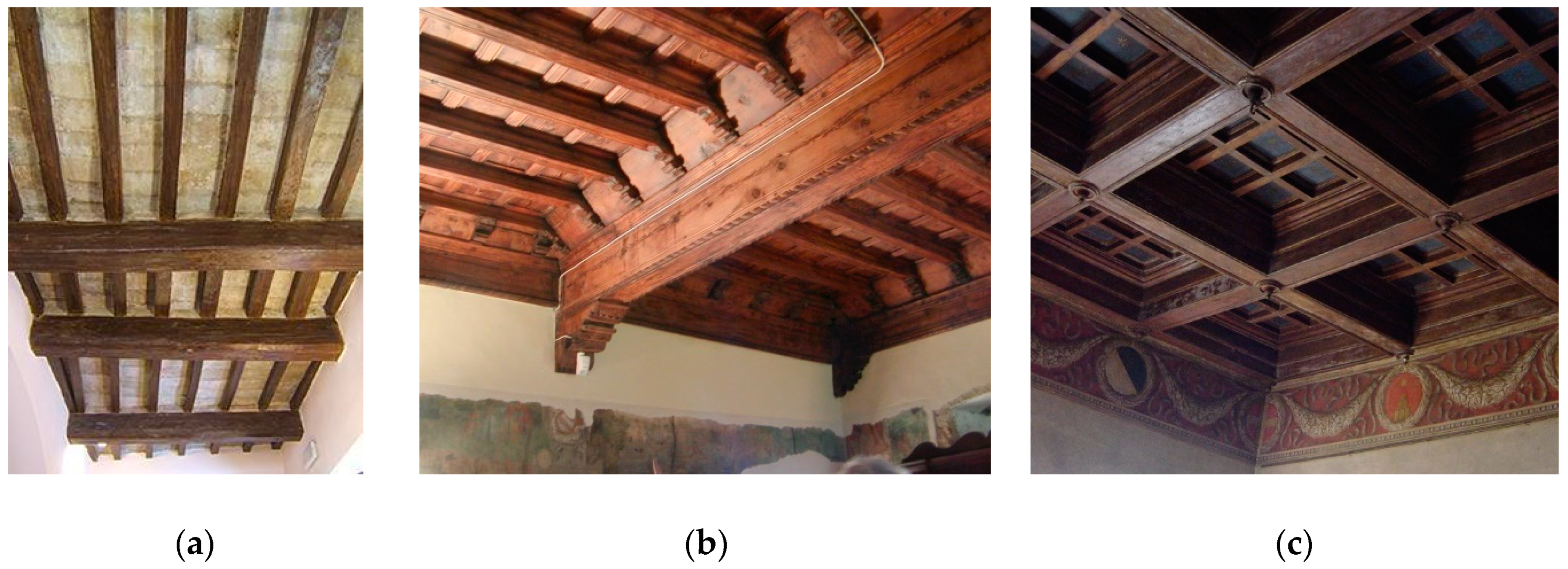
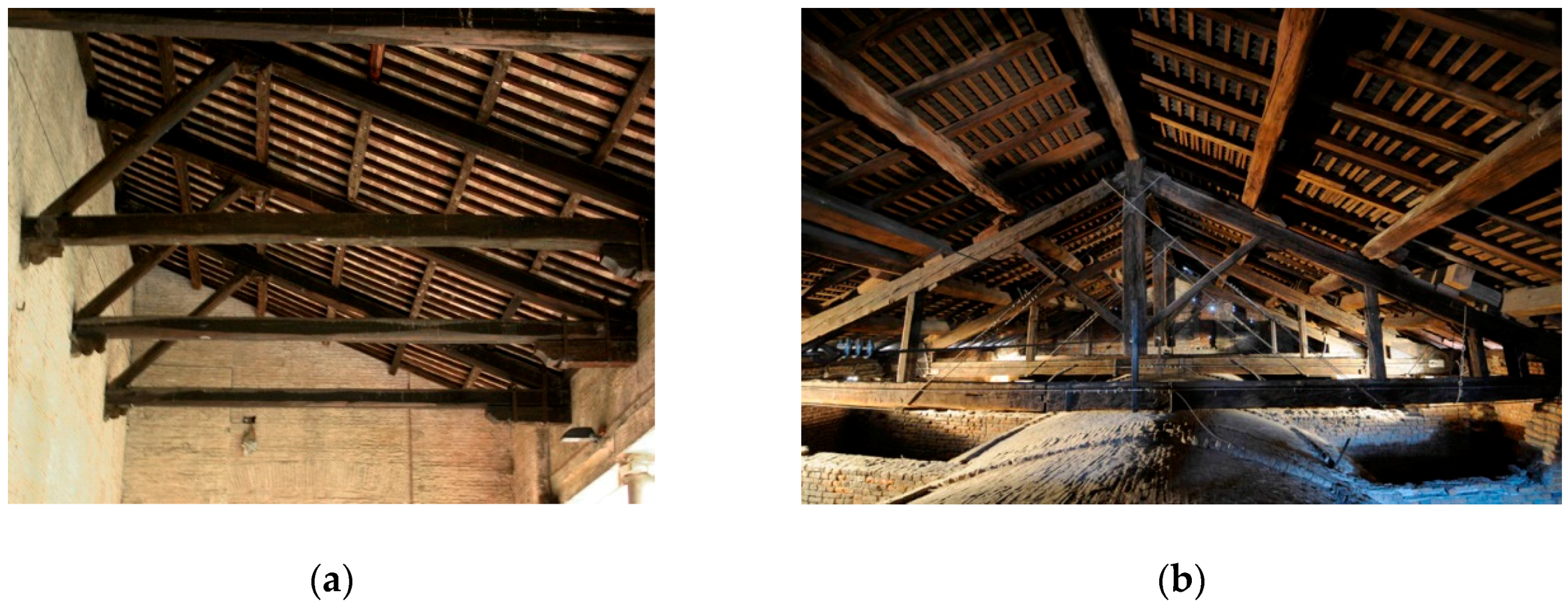
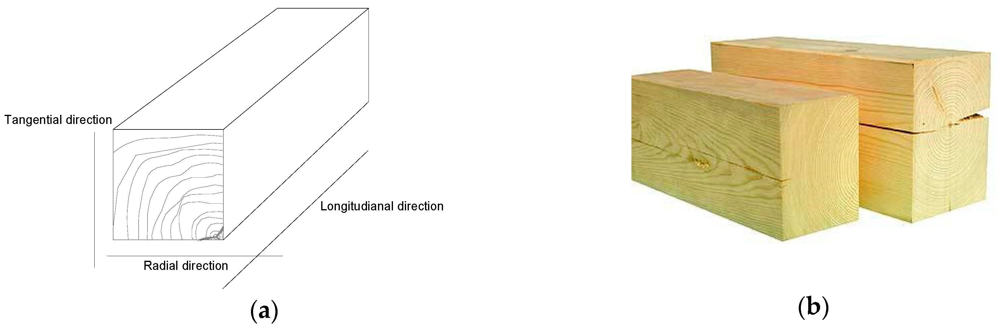
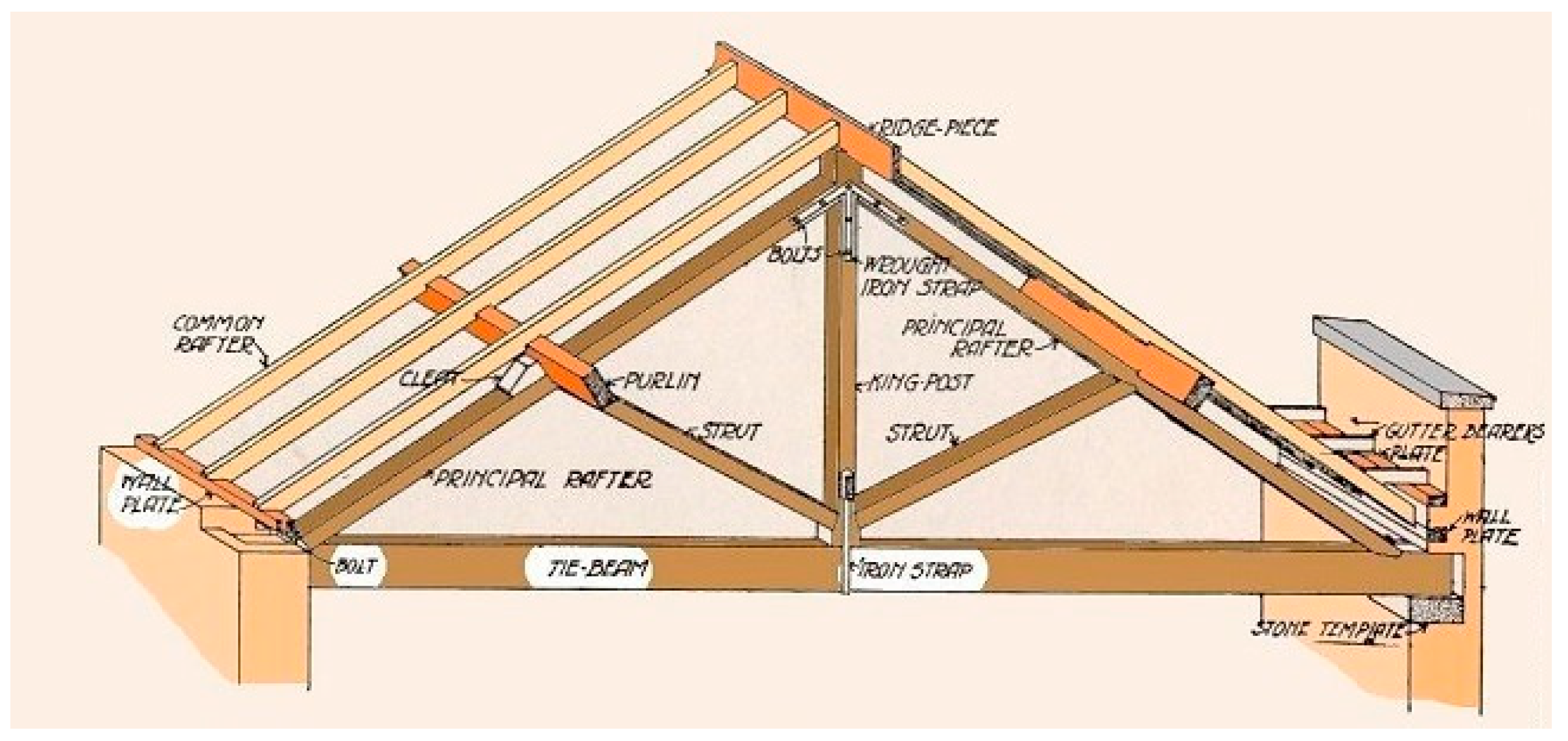
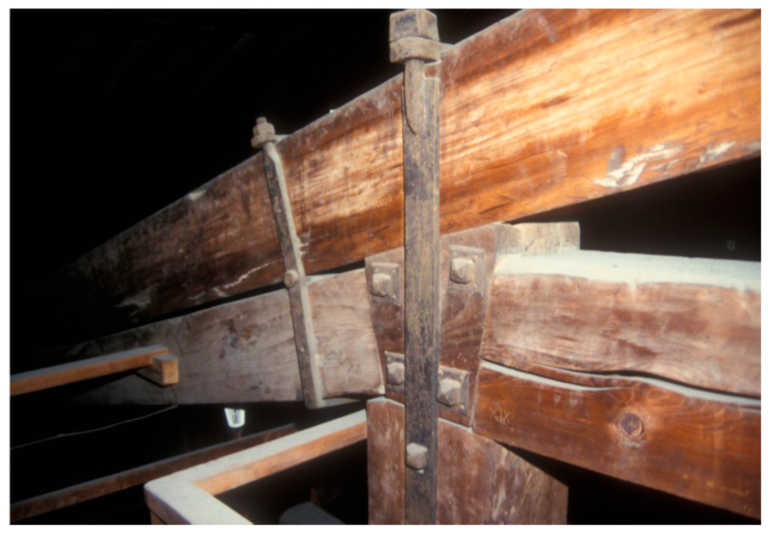
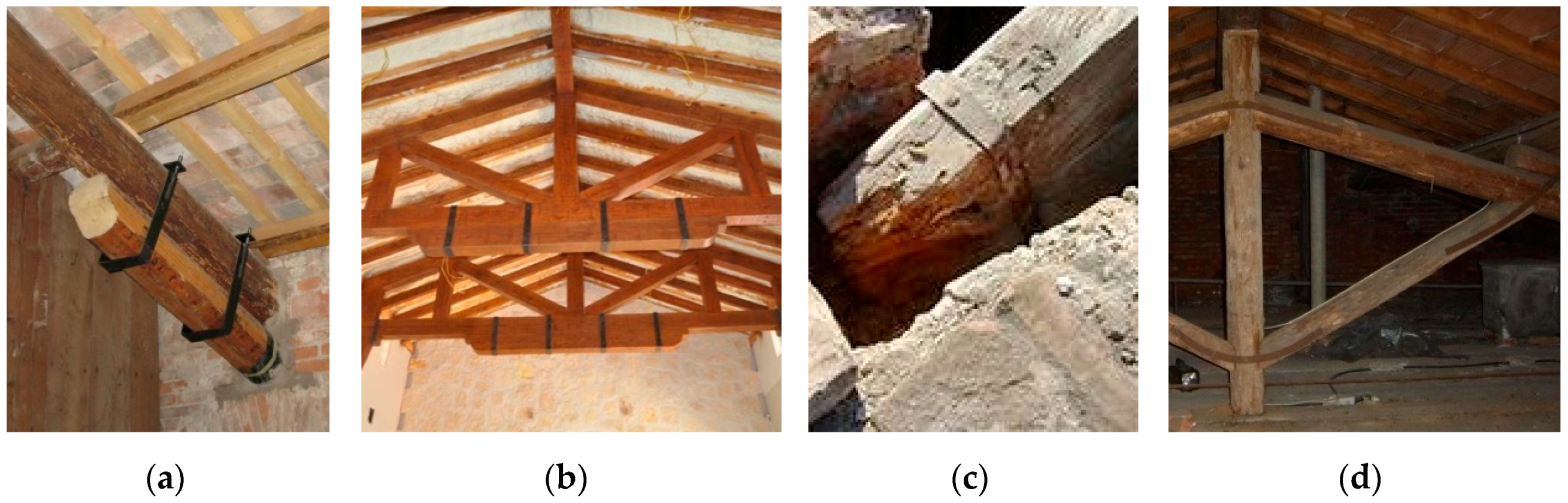
3. Typical Timber Historic Structures

Timber has been used for construction for centuries [32,33]. Buildings (both private and public) and infrastructures (bridges, aqueducts, towers, etc.) were usually partially or entirely made of timber structural elements due to their economic benefits (low cost, large supply in nature, ease to transport, work and use, high durability, simple maintenance) (Figure 3, Figure 4 and Figure 5). The main (technical) reason for its widespread historic use in construction is associated with its fibrous nature: this provide timber material with an excellent tensile and flexural strengths, making this material suitable for roof and floor structures (lintels, ties etc.).
Timber also exhibits high compressive strength. However, compressive stresses in historic constructions were typically resisted by masonry structural elements. In southern Europe and the Mediterranean basin, buildings often consist of vertical wall elements or pillars, assembled with lime mortar or (rarely) drystone construction, with a frequent use of timber beams for floors and roof structures [34,35]. Although timber is not a heavy material, it wasn’t easy or, given its availability, even necessary to transport it in the past from forests. Timber structures were typically made of wood species local to the immediate area.
Rotting timber is the main cause for repair (local) interventions on historic timber structures. Figure 6a,b show two critical points where repair is typically needed: the end (timber-to-masonry connection) of timber beam-floors and the joint between principal rafter and tie-beam for the traditional king post roof truss. As damp and moisture facilitate the attach of biotic agents (fungi, insects, larvae, etc.), unprotected areas are at high risk.
Creep and shrinkage of timber may cause damages (mechanical), leading to excessive deflection, reduction of structural stiffness and strength. Time-dependent deformation under a certain applied dead-load (creep) generally occurs at high temperature, but in timber it can also happen at room conditions. Figure 6c shows a deformed beam due to over-loading. Such deformation is typically produced by bending loads. Differential shrinkage along the three principal directions in timber (radial, tangential and longitudinal) (Figure 7) can cause high reductions of the second moment of inertia of a beam section and also facilitate the attack of biotic agents (insects, fungi, etc.). For mechanical-based damages, interventions with repair or reinforcement are usually required. For the traditional king post roof truss, the relevant terminology and used symbols are reported in Figure 8 [36].

4. Repair Methods

Damaged timber elements are usually repaired by local interventions [37,38]. Degradation near masonry supports or near the timber-to-timber joints are typical reasons for repair. The use of metal fasteners or profiles is not new, it is also found in repair interventions dated back to the 19th century. Steel and iron have frequently been used in the repair/reinforcement of timber members which may have decayed due to rot and insect infestation or fractured/deformed because of over-loading. Because of the risk of condensation on metals, iron and steel reinforcement should always be visible and open to inspection [39]. This problem could be overcome when stainless steel is used. Although the use of stainless steel often follows the traditional steel repair methods, new technical solutions and methods have been proposed in this area. Table 2 shows the repair methods described in this section, with some information about usability and appropriateness for different repair interventions. It should be remarked that the application of stainless steel elements is often combined with re-construction/repair of pre-existing timber-to-timber lock-joints. The correct use of lock-joints is extremely important in timber connections, following the multi-century-old carpentry tradition of joining timber elements.

4.1. Stainless Fasteners

The use of metal fasteners to reinforce local timber beams and trusses is a traditional technique (Figure 9). This was very common in the 19th and 20th centuries and it is still applied today [40,41]. The method simply consists in the application of one or more metal fasteners, made of metal strips, to prevent the slippage between two timber elements and increase the resisting section in critical areas. It is typically applied at the beam-to-template connection points and in the timber-to-timber joints of the traditional king post roof trusses (Figure 10).
A major cause of failures in metal fasteners in timber structures is electrochemical corrosion (rust), caused by the galvanic action. Considering that timber seasoning is not an irreversible process, timber members can absorb moisture. It is well known that air circulation is essential for adequate maintenance of timber structures, but areas under the metal strips typically have higher humidity than the rest of the timber structure and this has deleterious consequences for both the timber and metal materials. Furthermore, the direct contact of damp timber and the fasteners facilitate biotic attacks in the timber and corrosion in the metal. The use of stainless steel strips can partially solve the problem of corrosion. Stainless steel should be carefully selected: high-resilience, high-modulus and high PRE values are sought after characteristics for these applications. Stainless fasteners for repair interventions of historic structures are typically applied on-site by experienced mason. To prevent stainless steel cracking during on-site applications due to high bend angles (for example during wrapping of timber beams with rectangular cross sections), the stainless steel should have high ductile behavior and high resilience strength.

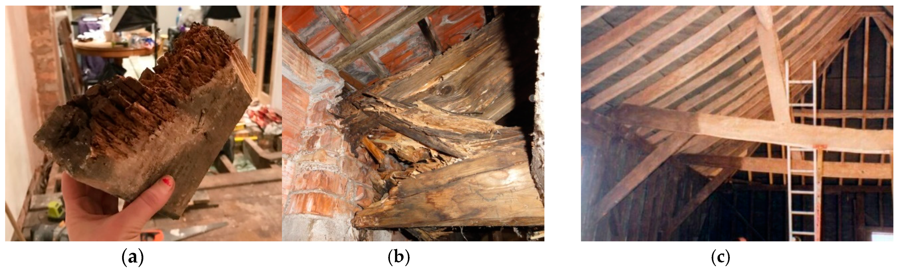
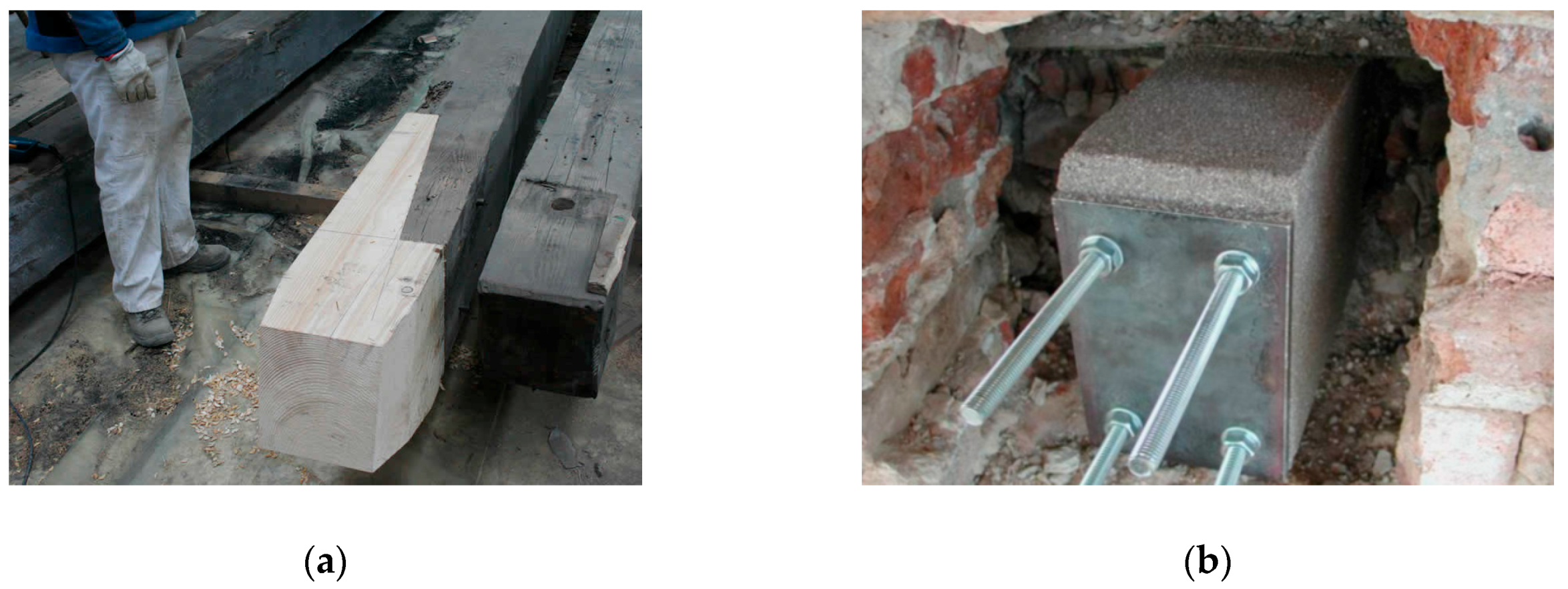
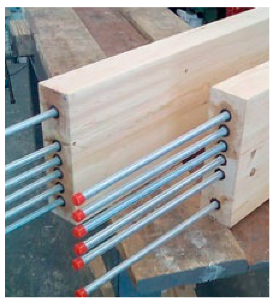
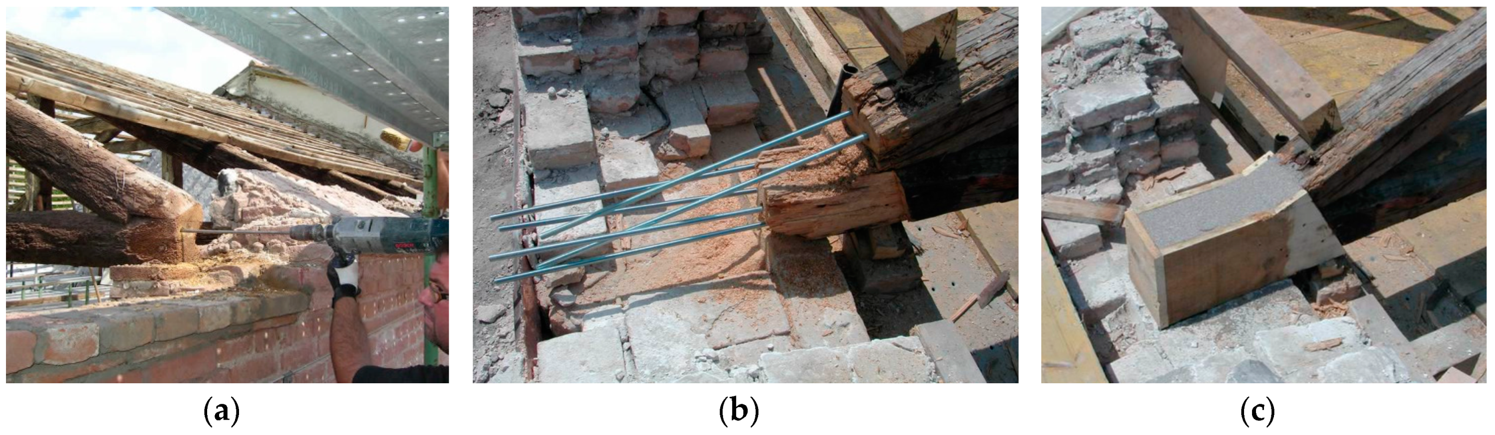
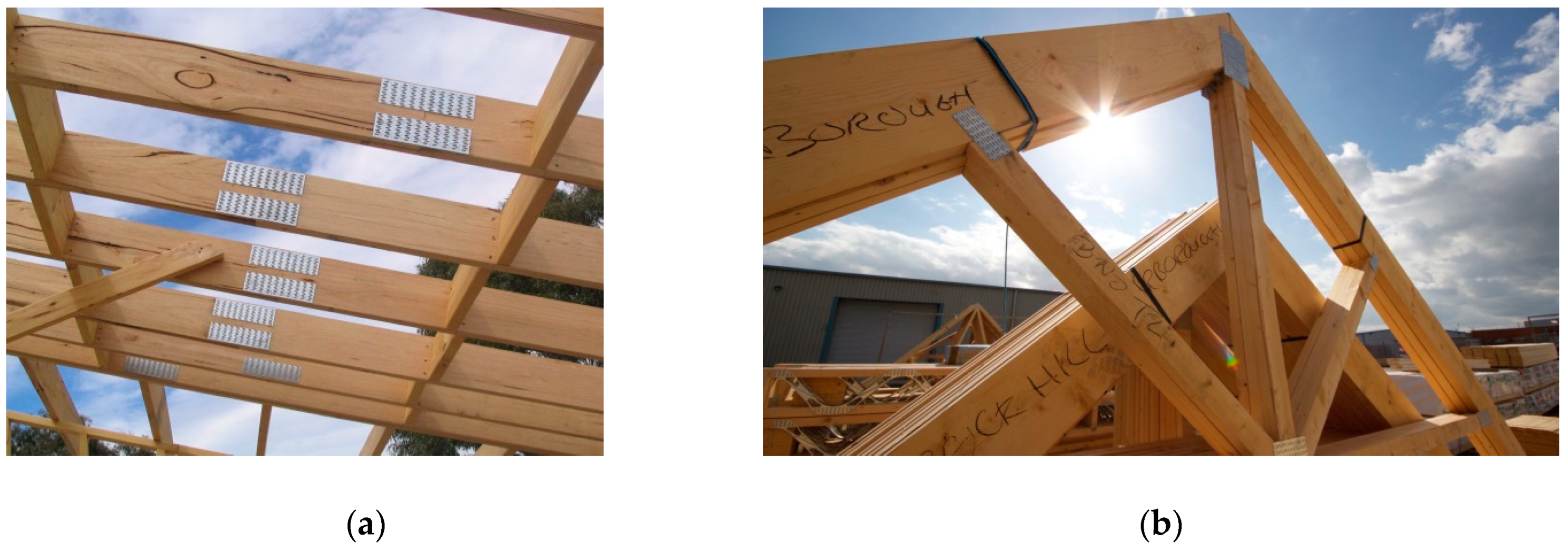
4.2. Re-construction of Beam Ends

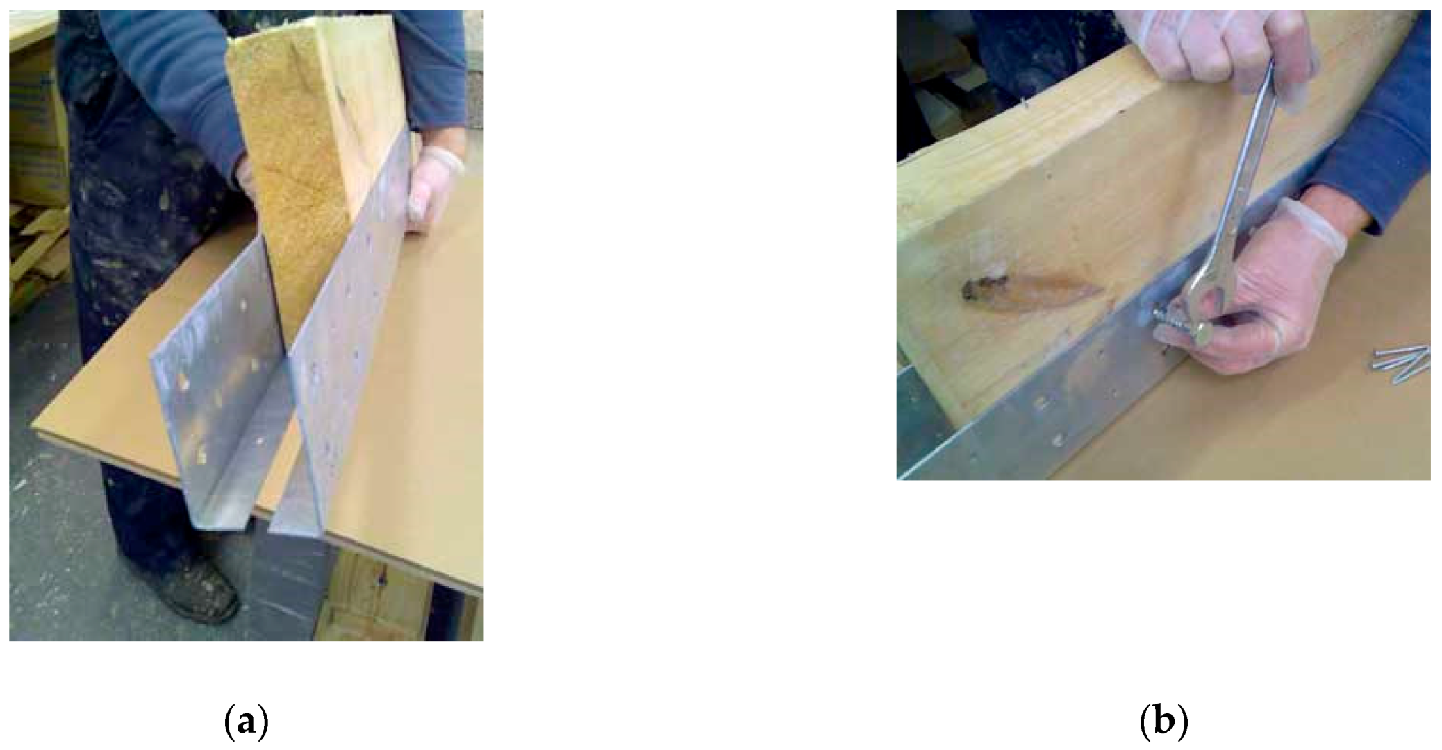
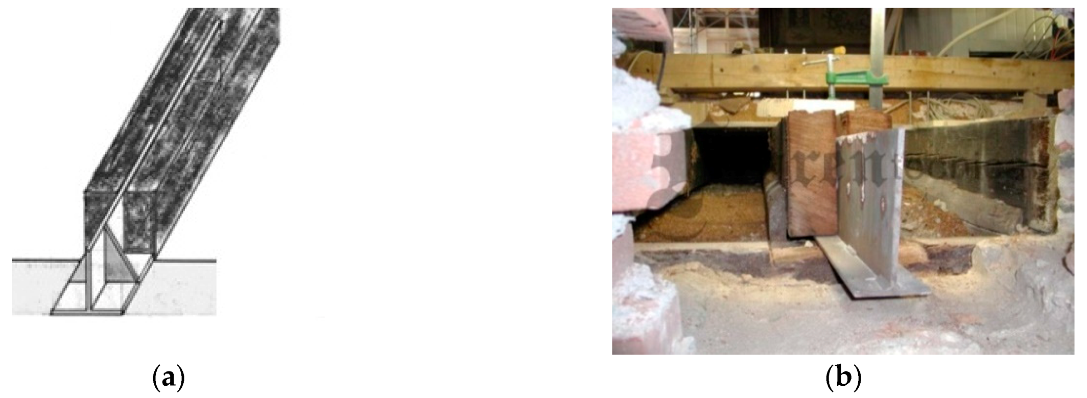
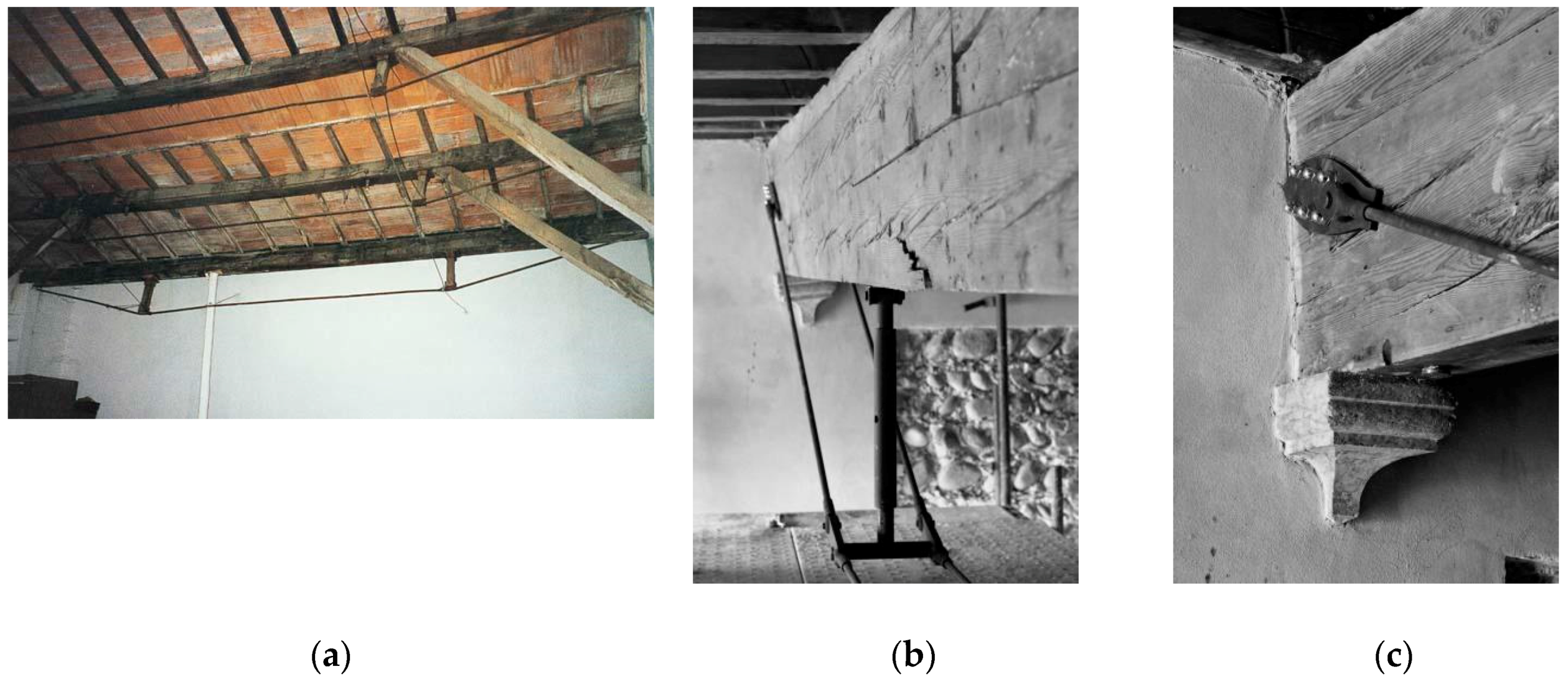
4.2.1. Use of Stainless Steel Sections

Figure 3 shows a typical joist floor. This one-way beam-floor is common in the UK, where it is still in use for new construction. To repair the joist ends from rotting at the point where the joists rest in brick or stone walls, pairs of stainless or galvanized steel plates, pre-drilled, are typically used with standard coach screws, which are secured at the end of degraded timber joists (Figure 11). The plates rest in or on the wall and allow for the rotted end to be cut off. To give additional stiffness, for use in rows of continuous end repairs, with no sound joist ends between. A bolted connection through the plates into the parent joist can be adopted [42,43,44].
To reinforce the decayed timber beam ends, stainless steel flitch plates can be inserted along the beam length (Figure 12). This method involves cutting a slot into the timber and making the beam a composite of stainless steel and timber. The plate may also take a T-shape either the right way up (top of the beam) or upside down (underside of the beam). The steel flitch plate is best used at the underside of the beam and fixed upside down, so the wide part of the T is positioned to carry the highest tensile stresses. However, the functionality of the composite beam depends on the type of connection between steel and timber members. When reinforcement is carried out at the ends of simply-supported beams, connection should be able to transfer only the shearing forces (zero bending moment at the supports). In this situation, bolts in the stainless steel web are sufficient. From a practical viewpoint, these are difficult repairs to carry out on site, requiring overhead cutting of the slot by multiple drillings or chain-morticer/chain-saw cutting.

4.2.2. Use of Stainless Steel Rods

For repairing old solid timber beams, lintels or rafters, it is also common to use timber prostheses to connect with the damaged beam using smooth or ribbed stainless steel rods, connectors or bars. Holes are drilled, or a groove cut, in the undamaged pre-existing timber to accommodate the rod reinforcement. The prosthesis is usually made of a new, laminated structural timber (Figure 13), made in kiln dried wood or epoxy paste (using construction shutters). The rods are typically made of fiberglass, carbon FRP or stainless steel (Figure 14 and Figure 15). Pouring or injection resins are used to fix the rods into the prostheses and the pre-existing beam [45,46,47,48].

4.2.3. Use of Nail Plates

Nail plates, made of stainless steel, can be used in various applications, mainly for new low-value timber constructions. Nail plates are typically used for repairing or joining timber elements or to increase the flexural stiffness of timber beams and joists. However, these plates are often used to connect wood elements in the same plain. Low carpentry skills are needed in order to construct a timber structure using nail-plated connections.
Although the use of nail plates can be considered a versatile and cost-effective method to improve the connection between wood elements (Figure 16), their use for historic or listed timber structures is rare and not often authorized by conservation bodies. This is mainly due to the fact that a nail-plate connecting system can cause damage to the timber structure, and facilitate biotic attack by saprophytic insects and fungi. For historic structures, it is always preferable to repair/restore the pre-existing historic connecting devices (post-and-beam, tie-and-rafter and other construction techniques). Furthermore, nail-plate connections are rarely able to transfer to maximum allowable internal force from one element to another [49,50].

5. Reinforcement Methods

Historic timber structures have to transfer external loads to the walls, dealing with the corresponding internal axial load, shearing force and bending moment. The stresses and deformations in the timber structures should not exceed the strength and deformation limits given by modern standards and building codes. Furthermore, the resisting sections of the structure and the mechanical properties of the timber has to be reduced due to mechanical and biological damage. In many situations, except for dismantling and reconstruction of the timber structure, the only option available for structural engineers is to apply a reinforcement. In this section, some traditional and innovative retrofitting solutions will be described and discussed. It should be recommended here that the on-site application of a bending reinforcement should always be preceded by a total or partial removal of the external loads, with the aim of facilitating the stress transfer to the reinforcement during future loading. When this is difficult to carry out, bending moment could be reduced by applying opposite external forces, using hydraulic loading cylinders.

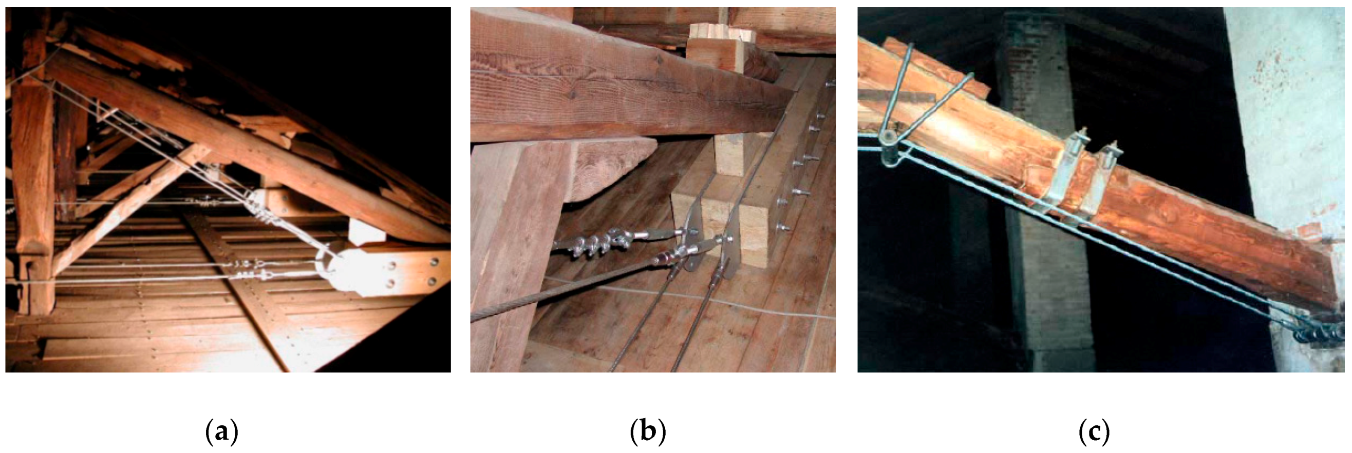
5.1. Reinforcement by Converting a Beam Element into a Trussed Girder

The conversion of a beam-floor into a trussed system is a traditional method, introduced in the 19th century to reinforce deficient timber-beam floors [53,54,55,56,57,58]. Figure 17a shows a retrofitting intervention carried out in the 1920s on a timber-beam floor in Italy. A more recent application is shown in Figure 17b,c. Nowadays, it is possible to use stainless steel bars, thus highly reducing corrosion problems. A critical aspect of this intervention is the creep deformation of both the timber and the stainless steel materials. Mechanical devices (turnbuckles) are often needed for the stainless ties and low-creep, high-modulus stainless steel alloys should be preferred.
Figure 18 shows different retrofitting interventions, designed by professor L. Jurina [54]. The use of stainless steel wire ropes may represent an interesting solution when the reinforcement is exposed and unprotected. The installation of the ropes is relatively easy, the intervention is reversible, and the damage to the timber structure is very limited. However, particular attention should be given to stress concentration problems at the rope-timber joints and it is recommended to take periodic measurements of the creep deformation of the stainless steel ropes. The joint between the wire rope (tie) and the timber rafter is made using two steel plates (Figure 18b). These are inserted into a glulam element connected to the diagonal timber rafter with a bolted connection. The wall-to-wire connection can be effectively realized using anchor bolts (Figure 18c).

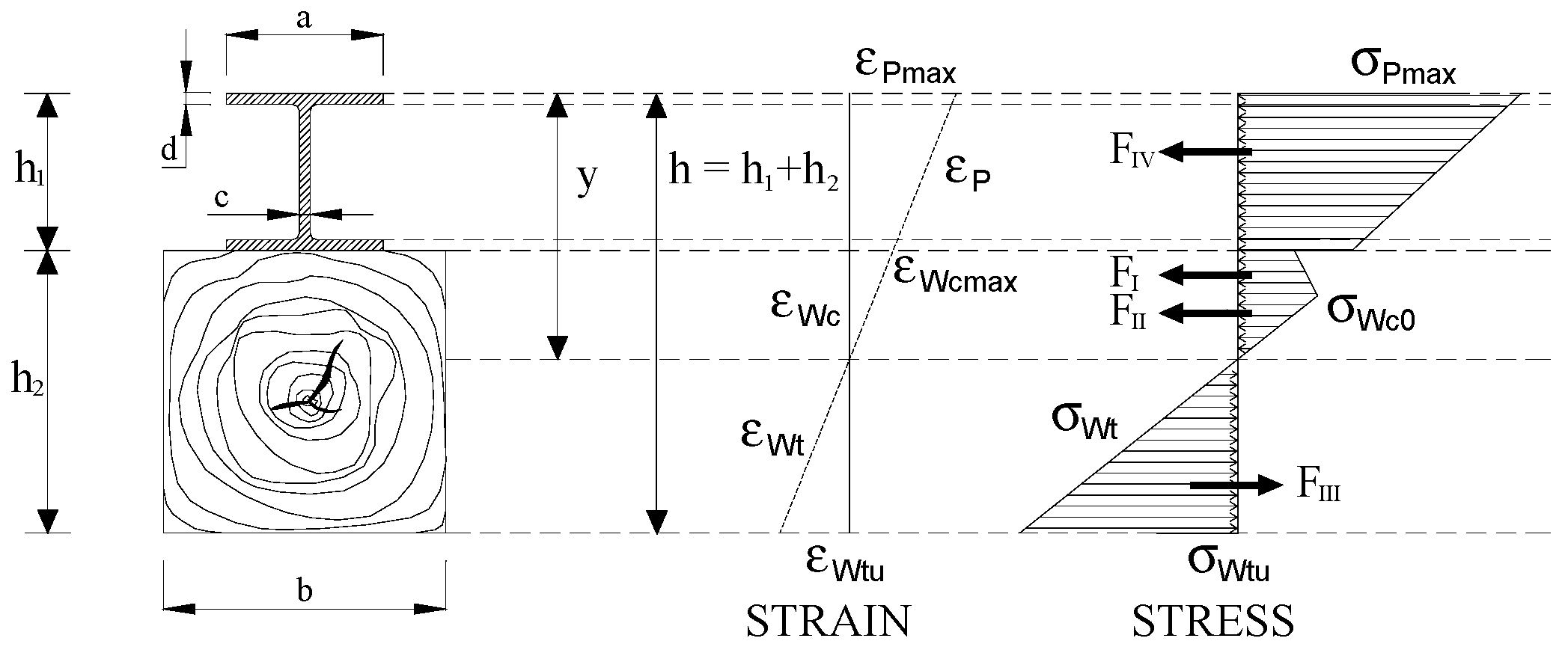
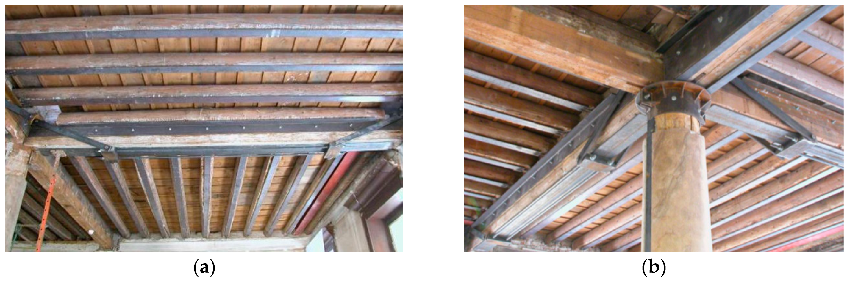
5.2. Reinforcement by Addition of Stainless Steel H-shaped Profiles

When conservation bodies or local authorities do not authorize retrofitting interventions, on listed buildings, at beam intrados (under the timber beams), for example, for the presence of decorations, it is possible to effectively reinforce timber-beam floors by operating on the beam extrados (over the beams) [58] (Figure 19 and Figure 20). In fact, to increase both the bending capacity and stiffness characteristics of existing wood beams, the use of stainless steel profiles placed in the compression side is an interesting solution. Stainless steel elements do not function as a substitute for the timber beams but rather effect an increase in their capacity and flexural stiffness through the creation of a mixed timber–stainless steel structure [59]. The application of stainless steel profiles can be done using epoxy resins, fasteners and/or metal screws or bolts. The use of mechanically attached connectors (screws or bolts) is usually preferred, given the high stress level, under loading, at interface between the timber beam and stainless steel beam. Stainless steel profiles can be also notched to better accommodate the floor joists, without highly affecting the effectiveness of the steel reinforcement. Furthermore, it should be noted that the reinforcement can be completely invisible behind the timber beams, it does not cause significant damage to the timber beams, and it can be easily removed, if needed, providing the method with reversibility characteristics. The reinforcement with H-type elements is characterized by this property and by high machinability of stainless steel elements to be carried out on-site. The reinforcement of timber beams using stainless steel beams is capable of resulting in a significant increase in strength, stiffness, and ductility and the application of the reinforcement is extremely fast and effective.

5.3. Reinforcement with Side Tension Rods or Plates

Stainless steel rods or plates can also be used as side tension reinforcement. This method simply consists of the application of a reinforcement at the bottom or either side of a timber beam under bending. This can be externally attached or bonded-in. When conversion into a trussed girder is not possible due to space constraints, a possible variation is to use side rods or plates. This method should be used with more caution as the smaller height of the timber-steel cross section produces higher stresses in both materials and problems related to stress concentration are likely to occur near the bolted joints.

5.3.1. Reinforcement with Externally Attached Steel Plates or Cords

Reinforcement of deficient timber beams using epoxy-bonded or screwed stainless steel plates or profiles is not a new technique. Several methods have been developed since the 1960s, which are particularly focused on reinforcing timber beams with steel elements, applied to the beam tension side and bonded by epoxy adhesives [60,61] (Figure 21). More recently, mechanically attached (bolted) stainless steel plates have been proposed with the aim of facilitating the removal of the reinforcement, when needed (the so-called requirement for “reversibility”) [62,63]. These reinforcement methods use wide steel plates, steel cords [64,65,66], I- or L-shaped profiles which cover a large part of the lateral or intrados (bottom) surfaces of the timber beam (Figure 22): this represents a limitation for the application of this reinforcement method, especially when the beams are painted, decorated or carved. Because wood is hygroscopic, its cellulose molecules attract water and, when stainless steel plates are used for reinforcement, areas under the plates could remain more humid and this could facilitate biotic attacks to the timber material.
When bolted joints are used to connect the plates to the timber, hardwood timber is more appropriate and suitable compared to softwood given higher parallel- and perpendicular-to-grain compressive strengths.
Furthermore, to avoid the risk of delamination of the stainless steel plate under bending loads, the timber surface should be sufficiently flat and smooth and the quantity of epoxy resin (bond-line thickness) should be as small as possible (0.5–3 mm). Delamination phenomena could also be induced by a defect in the timber material (usually a knot located on the tension side) and by the swelling and shrinkage, from cyclic moisture content variations in timber. The long term behavior of the epoxy bonding agent and its phase transformation could highly affect this reinforcement method: for these reasons it is always recommended to use mechanical devices (metal screws or bolts) to connect the plates with the timber beam. The main advantage of this reinforcement method is its rapidity of application. The timber beams are usually not notched or damaged during the reinforcement application.
The recent use of screwed connections is a revival of an old method in use long before strong adhesives became available in the construction market. This method includes the application of a stainless reinforcement using high-strength screws or bolts. This method has several advantages: it eliminates the use of organic adhesive (typically, an epoxy resin) and thus meets the requirement of reversibility of the reinforcement and compatibility with the wood material. For listed buildings, these are often essential conditions for authorization of reinforcement interventions by a statutory conservation body. However, one of the main limitations of the use of mechanical devices is the stress concentration that can occur near the screws/bolts. Because stress transfer from timber to stainless steel reinforcement is guaranteed by these devices, stress peaks can cause local failures and slippage phenomena between the two materials. Such phenomena can compromise the action of the reinforcement and should be studied and avoided. In order to prevent this, it is recommended to avoid the use of connecting mechanical devices for reinforcement of softwood beams.
Figure 23a shows the application of stainless steel cords. The application of the cords at the beam bottom is a relatively simple operation: an epoxy paste is needed to glue and protect the fibers on the beam surface (Figure 23b). The negligible bending stiffness of the stainless steel fibers also allows for pre-stressing them: a mechanical device, consisting of a metal cylinder, positioned at one beam end, can be used for this purpose. Fibers are wound around the metal cylinder (Figure 23c) using a clamp and fastened to the other end, until the design target-value of the clamping couple is reached. At the end of curing time of the epoxy paste (typically 48–72 h), the mechanical pre-stressing device can be removed. The final result is a timber beam strengthened, at the tension side, with pre-tensioned stainless steel cords.
Considering that the state of the timber material near the bonded surface is of critical importance for the stress transfer between timber and stainless steel, the wood decay should always be assessed by means of on-site penetration tests or similar non-destructive techniques.

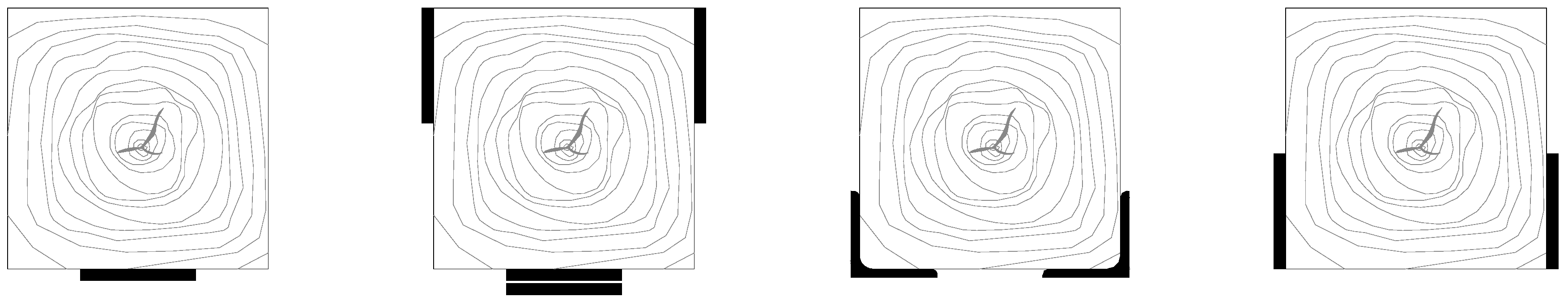
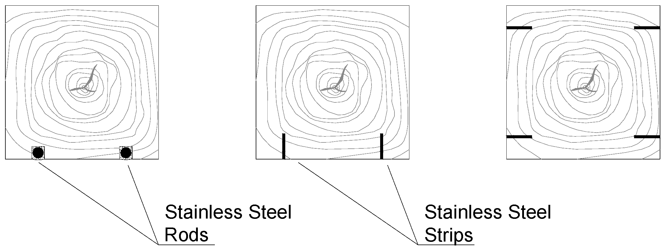
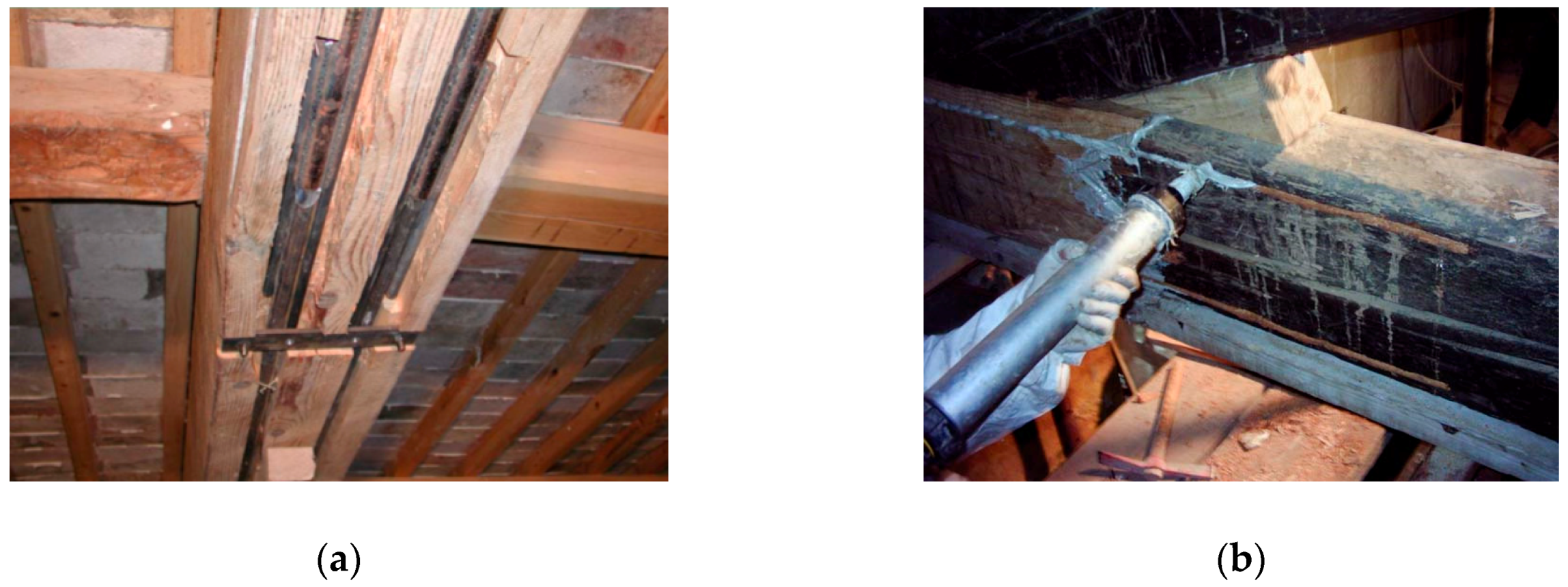
5.3.2. Reinforcement with Bonded-In Steel Rods or Strips

The introduction of FRPs in Civil Engineering in the 1980s facilitated the diffusion of bonded-in reinforcement methods. Glass or Carbon FRP rods were widely used to reinforce, on the tension side, deficient timber beams [67,68] (Figure 24). These composite elements are associated with high strength and stiffness to weight ratios. However, among the drawbacks of FRP rods is the linear elastic stress–strain relationship (brittle behavior) and the weak long-run response with high reductions of their tensile strength and stiffness. In such context, the replacement of FRP rods with stainless steel ones could be considered as a viable alternative solution. The reinforcement method consists of the application of stainless steel rods or strips in internal grooves, connected to the timber beam using structural adhesives (typically epoxy resins) [69,70,71,72]. A large variety of reinforcement configurations can be used, depending on many factors: presence of decorative ceilings, carved beams, fire protection requirements. The fire requirement for non-exposed surfaces is often the main reason for the exclusion of the use of externally bonded stainless steel plates.
It is worth noting that, because timber and resins differ in their reactions to variations in humidity and loading, high shear stresses and local failures could result from differential shrinkage and swelling at the adhesive bond.
Bonded-in stainless steel reinforcements has some drawbacks (Figure 25): timber beams are usually damaged due to the use of a groove cutter for the installation of the rods/strips, and the use of adhesives is not recommended, given their unsatisfactory long-term behavior. However, several positive characteristics can also be highlighted: because the reinforcement is confined in the groove and it is completely embedded in the resin, the risk of the delamination of the steel reinforcement is very low. Reinforcement delamination is typically induced both by bending loads (and resulting shear stresses at interface) and by the swelling and shrinkage of the wood. Furthermore, unlike the externally-applied reinforcements, glued to the beam’s sides or to the bottom surface, the choice of bonded-in methods allows the epoxy adhesive layer to be partially protected in case of fire by applying a longitudinal wooden board, which covers the groove.
When metal strips are used, it is recommended to apply them vertically. Figure 26 shows an on-site experimental investigation [71]: the 15th-century timber beams of an historic building in Brescia, Italy. The width of the grooves was 16 mm and the depth varied from 60 mm at the mid-span to 0 mm at the groove ends in order to minimize wood removal. Strips were 50 mm × 4 mm × 4200 mm in dimensions. They were applied vertically using both an epoxy resin and diagonal high strength steel nails.

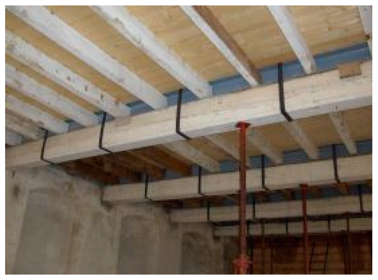
6. Reinforcement of Wooden Floors

The rehabilitation of historic buildings both for new use and occupancy often requires the reinforcement of the wooden floors. Reinforcement could be needed to increase the flexural capacity and stiffness (vertical static loading) or to improve the structural response against in-plane seismic loads (horizontal dynamic loading). In seismic prone areas, horizontal diagrams in buildings have the critical function to transfer the seismic loads from the walls perpendicular-to-the-seismic- direction to the parallel-to-the-seismic-direction walls (Figure 27). To achieve this, an increment of the lateral in-plane stiffness of wooden floors is often necessary.
To increase both the flexural and in-plane stiffnesses, an effective strengthening method consists in the use of stainless steel screws to connect a new Reinforced Concrete (RC) slab, typically applied over the floor, or a double-layer wooden floor boards to the existing timber joists or beams [73,74]. By preventing relative sliding between the new slab/boards and the underlying pre-existing timber structure, it is possible to highly increase the second moment of inertia of the resisting cross section [75,76,77,78,79,80].
In respect of the traditional reinforcement of one-way wooden floors with a steel mesh reinforced concrete (RC) slab (Figure 28), it is important to document research efforts on the use of stainless steel studs. These are typically used to connect the new RC slab with the pre-existing underlying timber structure [81,82,83]. The advantages of this method are numerous: the bending stiffness and capacity of the floor are highly enhanced (given the increment of the second moment of inertia of the cross section); the in-plane response of the floor is also improved as the steel-mesh reinforcement is able to provide the needed tensile strength to the RC slab. If the floor or the RC slab is properly connected to the load-bearing walls, the seismic response of the building can be significantly enhanced.
The damage produced to the timber beams/rafter due to the application of the stainless steel studs is negligible. However, it should be remarked that the application of RC slab can also increase the magnitude of the dead load (Figure 28b). A mitigation measure of this problem is the use of autoclaved aerated concrete (Figure 28c), but this should be applied with caution given the reduced mechanical properties of this type of concrete. However, the use of autoclaved aerated concrete can produce savings in terms of energy consumption, given its highly thermally insulating properties. Different types of connectors are available in the construction market. Examples are shown in Figure 29.
The use of low-cost boards is an interesting solution, given also its positive characteristics in increasing the thermal insulation of the building and thus reducing its energy usage (Figure 30). However, while this method is usually effective for static vertical loads, its effectiveness is limited in seismic prone areas, as the boards are typically made of plywood or are particle-made boards. Their in-plane stiffness and strength is usually low and the boards are usually subjected to swelling due to moisture absorption. The use of large solid-wood boards, effectively connected to the underneath joists, can solve the problem, but this usually lead to an increase in the cost of the intervention.
Figure 31 shows a schematic layout of the reinforcement of wooden floor by adding a new layer of wood boards. These can be effectively connected to the underneath wooden floor boards and timber beams by using inclined high-strength stainless screws. A variation of the reinforcement method in Figure 31 consists of the application of diagonal stainless steel strips [80] (Figure 32), screwed to the pre-existing underlying wood boards and beams/joists.

7. Future Developments and Possibilities

Stainless steel does not refer to a single material but to a family of corrosion resistant steels and its use for repair and retrofit of timber structures may vary with different solutions and possibilities. The main obstacle to its widespread diffusion is not its high cost (from 2 to 20 times higher compared to carbon steel), but limitations in engineers’ and architects’ knowledge of its mechanical properties and characteristics. In many situations, this material is lumped with standard carbon steel with the additional property of higher corrosion resistance. This is somewhat simplistic. Its yield strength can vary from 180 to >580 MPa. Worldwide demand for stainless steel is increasing at a rate of about 5% per annum and annual consumption is now well over 20 million tonnes and still rising. New uses are being continuously found for its attractive appearance, corrosion resistance, low maintenance and high strength. Furthermore, stainless steel has no need for painting or other protective coatings. Reinforcements of timber structures are often left unprotected and exposed. In this situation the use of stainless steel fits well with the need for corrosion resistance and low maintenance. The more specific requirement for reversibility of the repair/reinforcement intervention emphasizes the importance of screwed and mechanically attached applications of reinforcement: in this area, the use of stainless steel has several advantages over bonded composite reinforcements. Finally, there are two additional positive characteristics of stainless steel when compared to composite materials: its negligible mechanical degradation with time (ageing) and its isotropic behavior. Unlike composite materials, stainless steel has a satisfactory response when loaded in different directions, and also when bended or loaded over the yield strength.
Another important factor to consider in civil applications is the ductile behavior. Ductility tends to be defined by the % elongation during a standard tensile test. The elongation for austenitic stainless steels is quite high (Figure 2) and this is considered positive for timber structures exposed to earthquake actions. Furthermore, cryogenic (low temperature) resistance is also high and the use of stainless steel for reinforcement and repair of outdoor timber structures is quite straightforward: at cryogenic temperatures the tensile strengths of austenitic stainless steels are substantially higher than at ambient temperatures. All these factors mean stainless steel can be economically viable for repair and reinforcement of timber structures once service life and life-cycle costs are considered.

8. Conclusions

Metal methods of strengthening and repairing timber structures have been in use for about 200 years. Surveys, analyses and recordings of these methods have been undertaken. Information on the ways in which metals-timber joints behave is also presented. A major cause of failures in metal reinforcements of timber structures is electrochemical corrosion (rust), caused by the galvanic action, facilitated by the absorption of the air humidity from timber members.
Today, the use of stainless steel profiles, strips, screws, rods represent an interesting solution to the problem of corrosion of metal reinforcements. Stainless steel can provide an efficient and durable method of reinforcement and for making connections in timber structures. Furthermore, for pre-existing, old and historic timber structures, recent seismic codes allow internal stresses to be higher than the elastic limit and typically require that the timber members exhibit a sufficient post elastic behavior, in terms of deformation and dissipation capacities. In such context, the use of stainless steel could be considered as an interesting solution, given the intrinsic plasticity of the stainless steel material. Brittle materials (i.e., glass or carbon fibres) should be avoided, as much as possible, in areas of high stress concentration or dissipating zones.
This paper summarized the actual use of stainless steel in repair and reinforcement of deficient timber structures. It has been demonstrated that the use of stainless steel is nowadays common in such applications. However, structural engineers often have a superficial technical knowledge of stainless steel. The different stainless typologies for structural applications, the pitting resistance, the post-elastic behavior and mechanical properties remain sometimes unclear to them. This information could be even more important when numerical models are implemented to capture the structural response of stainless steel repaired or reinforced timber structures.
In addition to more traditional solutions (use of stainless steel fasteners, conversion of a timber beam element into a trussed girder), more recent solutions have been discussed in this paper. Most of these solutions are not new and were introduced in the 1980s and 1990s. However, it should be remarked that a repair or reinforcement intervention on historic structures should not cause a substantial modification of the original structural conception and adhere with the principle of “minimum intervention and maximum retention of materials” and low invasiveness.

Author Contributions

Conceptualization, M.C. and A.B.; writing—original draft preparation, A.I.O. and M.C.; writing—review and editing; supervision, M.C. and A.I.O.

Funding

This research received no external funding.

Acknowledgments

The authors wish to thank Marco Frigo of Outokumpu.

Conflicts of Interest

The authors declare no conflict of interest.

References

  1. Gedge, G. Structural uses of stainless steel—Buildings and civil engineering. J. Constr. Steel Res. 2008, 64, 1194–1198. [Google Scholar] [CrossRef]
  2. Gedge, G. Duplex steels for durable bridge construction. In Proceedings of the International Association for Bridge and Structural Engineering (IABSE) Conference, Weimar, Germany, 16–21 September 2007. [Google Scholar]
  3. Baddoo, N.R.; Burgan, B. Structural Design of Stainless Steel; Steel Construction Institute: London, UK, 2001; SCI P291. [Google Scholar]
  4. McGurn, J.F. Stainless steel reinforcing bars in concrete. In Proceedings of the Intern. Conference of Corrosion and Rehabilitation of Reinforced Concrete Structures FHWA, Orlando, FL, USA, 7–11 December 1998. [Google Scholar]
  5. Baddoo, N.R. Stainless steel in construction: A review of research, applications, challenges and opportunities. J. Constr. Steel Res. 2008, 64, 1199–1206. [Google Scholar] [CrossRef]
  6. Venice Charter. International charter for the conservation and restoration of monuments and sites. In Proceedings of the 2nd International Congress of Architects and Technicians of Historical Monuments, Venice, Italy, 25–31 May 1964. [Google Scholar]
  7. Krakow Charter. Principles for conservation and restoration of built heritage. In Proceedings of the International Conference on Conservation, Krakow, Poland, 23–24 November 1998. [Google Scholar]
  8. Pleviris, N.; Triantafillou, T.C. FRP-reinforced wood as structural material. J. Mater. Civ. Eng. 1992, 4, 300–317. [Google Scholar] [CrossRef]
  9. Triantafillou, T.C. Shear reinforcement of wood using FRP materials. J. Mater. Civ. Eng. 1997, 9, 65–69. [Google Scholar] [CrossRef]
  10. Borri, A.; Corradi, M.; Grazini, A. FRP reinforcement of wood elements under bending loads. In Proceedings of the 10th International Conference on Structural Faults + Repair, London, UK, 1–3 July 2003. [Google Scholar]
  11. Gentile, C.; Svecova, D.; Rizkalla, S.H. Timber beams strengthened with GFRP bars: Development and applications. J. Compos. Constr. 2002, 6, 11–20. [Google Scholar] [CrossRef]
  12. Borri, A.; Corradi, M.; Grazini, A. A method for flexural reinforcement of old wood beams with CFRP materials. Compos. Part B Eng. 2005, 39, 143–153. [Google Scholar] [CrossRef]
  13. Miceli, F.; Scialpi, V.; La Tegola, A. Flexural reinforcement of glulam timber beams and joints with Carbon Fiber-Reinforced Polymer rods. J. Compos. Constr. 2005, 9, 337–347. [Google Scholar] [CrossRef]
  14. Gilfillan, J.; Gilbert, S.; Patrick, G. The use of FRP composites in enhancing the structural behavior of timber beams. J. Reinf. Plast. Compos. 2003, 22, 1373–1388. [Google Scholar] [CrossRef]
  15. Chu, W.; Wu, L.; Karbhari, V.M. Durability evaluation of moderate temperature cured E-glass/vinylester systems. Compos. Struct. 2004, 66, 367–376. [Google Scholar] [CrossRef]
  16. Karbhari, V.M.; Chin, J.W.; Hunston, D.; Benmokrane, B.; Juska, T.; Morgan, R.; Lesko, J.J.; Sorathia, U.; Reynaud, D. Durability gap analysis for Fiber-Reinforced Polymer composites in civil infrastructure. J. Compos. Constr. ASCE 2003, 7, 238–247. [Google Scholar] [CrossRef]
  17. Krempl, E. An experimental study of room-temperature rate sensitivity, creep and relaxation of AISI 304 stainless steel. J. Mech. Phys. Solids 1979, 27, 363–375. [Google Scholar] [CrossRef]
  18. ICOMOS International Wood Committee. Principles for the Preservation of Historic Timber Structures; ICOMOS General Assembly: Guadalajara, Mexico, 1999. [Google Scholar]
  19. Camanho, P.; Hallett, S. Composite Joints and Connections: Principles, Modelling and Testing; Woodhead Publishing: Cambridge, UK, 2011. [Google Scholar]
  20. EN10088 Part 1 Stainless Steels Part 1—List of Stainless Steels; BSI: London, UK, 1995.
  21. EN10088 Part 2 Stainless Steels. Technical Delivery Conditions for Sheet/Plate and Strip of Corrosion Resisting Steels for General Purposes; BSI: London, UK, 2005.
  22. Sanstrom, R.; Bergqvist, H. Temperature dependence of tensile properties and strengthening of nitorgen alloyed austenitic stainless steels. Scand. J. Metall. 1977, 6, 156–169. [Google Scholar]
  23. Di Schino, A.; Longobardo, M.; Turconi, G.L.; Porcu, G.; Scoppio, L. Metallurgical design and development of C125 grade for mild sour service application. In Proceedings of the NACE—International Corrosion Conference, San Diego, CA, USA, 12–16 March 2006; pp. 061251–0612514. [Google Scholar]
  24. Di Schino, A.; Kenny, J.M.; Salvatori, I.; Abbruzzese, G. Modelling primary recrystallization and grain growth in a low nickel austenitic stainless steel. J. Mater. Sci. 2001, 36, 593–601. [Google Scholar] [CrossRef]
  25. International Molybdenum Association. Practical Guidelines for the Fabrication of Duplex Stainless Steels; IMOA: London, UK, 2014. [Google Scholar]
  26. Outokumpu. Available online: http://www.outokumpu.com/SiteCollectionDocuments/Outokumpu -Product-Range-Wallchart.pdf (accessed on 14 November 2018).
  27. European Standard EN ISO 15156-1:2015, NACE MR0175 Petroleum and Natural Gas Industries—Materials for Use in H2S-Containing Environments in Oil and Gas Production—Part 1: General Principles for Selection of Cracking-Resistant Materials; ISO: Geneva, Switzerland, 2015.
  28. National Association of Corrosion Engineers (NACE). TM-01-69:1995 (R2000)—Laboratory Corrosion Testing of Metals; NACE: Houston, TX, USA, 2000. [Google Scholar]
  29. Corradi, M.; Di Schino, A.; Borri, A.; Rufini, R. A review of the use of stainless steel for masonry repair and reinforcement. Constr. Build. Mater. 2018, 181, 335–346. [Google Scholar] [CrossRef]
  30. General Technical Delivery Conditions. European Standard EN 10025-1:2004 Hot Rolled Products of Structural Steels; CEN European Committee for Standardisation: Brussels, Belgium, 2004. [Google Scholar]
  31. Di Caprio, G. Gli Acciai Inossidabili; Hoepli: Milan, Italy, 2003. [Google Scholar]
  32. Panshin, A.J.; deZeeuw, C. Textbook of Wood Technology, 4th ed.; McGraw–Hill: New York, NY, USA, 1980. [Google Scholar]
  33. Parisi, M.A.; Piazza, M. Restoration and strengthening of timber structures: Principles, criteria, and examples. Pract. Period. Struct. Des. Constr. 2007, 12, 177–185. [Google Scholar] [CrossRef]
  34. Barbaro, D. I Dieci Libri Dell’architettura di M. Vitruvio; Il Polifilo: Milan, Italy, 1997. [Google Scholar]
  35. Tampone, G. Conservation of Historic Wooden Structures; Hoepli: Florence, Italy, 2005. [Google Scholar]
  36. Unalansusam. Available online: http://unalansusam.com/roof-struts/kptruss-digital-art-gallery-roof- struts/ (accessed on 23 November 2018).
  37. Tampone, G.; Mannucci, N.; Macchioni, N. Strutture di Legno. Cultura Conservazione Restauro; De Lettera: Rome, Italy, 2002. [Google Scholar]
  38. Mariani, M. Consolidamento Delle Strutture Lignee con L’acciaio; DEI: Rome, Italy, 2004. [Google Scholar]
  39. Charles, F.W.B. Dismantling, Repairing and Rebuilding as a Means of Conservation. In Proceedings of the ICOMOS UK: Timber Engineering Conference, London, UK, 8 April 1992. [Google Scholar]
  40. Bulleit, W.M. Reinforcement of wood materials: A review. Wood Fiber Sci. 2007, 16, 391–397. [Google Scholar]
  41. Giordano, G. Tecnica Delle Costruzioni in Legno; Hoepli: Milan, Italy, 1999. [Google Scholar]
  42. Franke, S.; Franke, B.; Harte, A.M. Failure modes and reinforcement techniques for timber beams–State of the art. Constr. Build. Mater. 2015, 97, 2–13. [Google Scholar] [CrossRef]
  43. Buildingconservation. Available online: http://www.buildingconservation.com/articles/structural-timber- repairs/structural-timber-repairs.htm (accessed on 21 October 2018).
  44. Joist-repair. Available online: https://www.joist-repair.co.uk/joistendrepair_diydoc.htm (accessed on 3 December 2018).
  45. Fiorentecnica. Available online: http://www.fiorentecnica.it/paginaintx02.html (accessed on 25 November 2018).
  46. Alessandri, C.; Mallardo, V.; Pizzo, B.; Ruocco, E. The roof of the Church of the Nativity in Bethlehem: Structural problems and intervention techniques. J. Cult. Herit. 2012, 13, 70–81. [Google Scholar] [CrossRef]
  47. Pizzo, B.; Gavioli, M.; Lauriola, M.P. Evaluation of a design approach to the on-site structural repair of decayed old timber end beams. Eng. Struct. 2013, 48, 611–622. [Google Scholar] [CrossRef]
  48. Resine-epossidiche. Available online: https://resine-epossidiche.it/edilizia-conservativa/ (accessed on 25 November 2018).
  49. Blass, H.J.; Schmid, M.; Litze, H.; Wagner, B. Nail plate reinforced joints with dowel-type fasteners. In Proceedings of the 6th World Conference on Timber Engineering, British Columbia, Canada, 31 July–3 August 2000. [Google Scholar]
  50. Karadelis, J.N.; Brown, P. Punched metal plate timber fasteners under fatigue loading. Constr. Build. Mater. 2000, 14, 99–108. [Google Scholar] [CrossRef]
  51. Fordevr. Available online: https://www.fordevr.com/nail-plate-construction.html (accessed on 10 January 2019).
  52. Beauty. Available online: http://beauty.fzl99.com/gang-nail-truss-plates/ (accessed on 10 January 2019).
  53. Studiofornale. Available online: http://www.studiofornale.it/intervento-di-consolidamento-trave-in-legno-lesionata-con-.contraffisso-metallico/ (accessed on 15 December 2018).
  54. Larsen, K.E.; Marstein, N. Conservation of historic timber structures: An ecological approach. In Butterworth-Heinemann Series in Conservation and Museology; Butterworth Heinemann: Oxford, UK, 2000. [Google Scholar]
  55. Jurina, L. L’uso Dell’acciaio nel Consolidamento delle Capriate e dei Solai in Legno. 2004. Available online: http://www.jurina.it/10/2012/02/2011_L%E2%80%99uso-dell%E2%80%99acciaio-nel-consolidamento-delle- capriate-e-dei-solai-in-legno.pdf (accessed on 21 January 2019).
  56. New South Wales State Heritage Office. The Maintenance Series, Timber Repairs, Information Sheet 5.2; New South Wales State Heritage Office: Sidney, Australia, 1998. [Google Scholar]
  57. Song, J.K.; Kim, S.Y.; Yang, K.H.; Han, S.A. Flexural behavior of post-tensioned glued-laminated timber with wire rope. In Proceedings of the International Conference on Sustainable Building Asia, Seoul, Korea, 27–29 June 2007. [Google Scholar]
  58. Corradi, M.; Borri, A. Fir and chestnut timber beams reinforced with GFRP pultruded Elements. J. Compos. Part B 2007, 38, 172–181. [Google Scholar] [CrossRef]
  59. Borgin, K.B.; Loedolff, G.F.; Saunders, G.R. Laminated wood beams reinforced with steel strips. J. Struct. Div. 1968, 94, 1681–1706. [Google Scholar]
  60. Alam, P.; Ansell, M.P.; Smedley, D. Mechanical repair of timber beams fractured in flexure using bonded-in reinforcements. Compos. Part B Eng. 2009, 40, 95–106. [Google Scholar] [CrossRef]
  61. Jasieńko, J.; Nowak, T.P. Solid timber beams strengthened with steel plates—Experimental studies. Constr. Build. Mater. 2014, 63, 81–88. [Google Scholar] [CrossRef]
  62. Corradi, M.; Borri, A.; Castori, G.; Speranzini, E. Fully reversible reinforcement of softwood beams with unbonded composite plates. Compos. Struct. 2016, 149, 54–68. [Google Scholar] [CrossRef] [Green Version]
  63. Corradi, M.; Vo, T.P.; Poologanathan, K.; Osofero, A.I. Flexural behaviour of hardwood and softwood beams with mechanically connected GFRP plates. Compos. Struct. 2018, 206, 610–620. [Google Scholar] [CrossRef]
  64. Resinproget. Available online: http://www.resinproget.it/bverona.html (accessed on 21 January 2019).
  65. Ghanbari Ghazijahani, T.; Jiao, H.; Holloway, D. Composite timber beams strengthened by steel and CFRP. J. Compos. Constr. 2017, 21, 04016059. [Google Scholar] [CrossRef]
  66. Borri, A.; Corradi, M. Strengthening of timber beams with high strength steel cords. Compos. Part B Eng. 2011, 42, 1480–1491. [Google Scholar] [CrossRef] [Green Version]
  67. Raftery, G.M.; Kelly, F. Basalt FRP rods for reinforcement and repair of timber. Compos. Part B Eng. 2015, 70, 9–19. [Google Scholar] [CrossRef]
  68. Bainbridge, R.; Mettem, C.; Harvey, K.; Ansell, M. Bonded-in rod connections for timber structures-development of design methods and test observations. Int. J. Adhes. Adhes. 2002, 22, 47–59. [Google Scholar] [CrossRef]
  69. Wu, W.; Gou, H. Analyzing of the timber beams of ancient buildings strengthened with NSM stainless steel bars. Int. J. Sci. 2015, 2, 77–87. [Google Scholar]
  70. Lantos, G. The flexural behavior of steel reinforced laminated timber beams. Wood Sci. 1970, 2, 136–143. [Google Scholar]
  71. Metelli, G.; Preti, M.; Giuriani, E. On the delamination phenomenon in the repair of timber beams with steel plates. Constr. Build. Mater. 2016, 102, 1018–1028. [Google Scholar] [CrossRef]
  72. Bulleit, W.M.; Sandberg, L.B.; Woods, G.J. Steel-reinforced glued laminated timber. J. Struct. Eng. 1989, 115, 433–444. [Google Scholar] [CrossRef]
  73. Branco, J.M.; Tomasi, R. Analysis and strengthening of timber floors and roofs. In Structural Rehabilitation of Old Buildings; Costa, A., Miranda Guedes, J., Varum, H., Eds.; Springer: Berlin, Germany, 2013; pp. 235–258. [Google Scholar]
  74. Turrini, G.; Piazza, M. Una tecnica di recupero dei solai in legno. Recuperare 1983, 5, 396–407. [Google Scholar]
  75. Modena, C.; Valluzzi, M.R.; Garbin, E.; da Porto, F. A strengthening technique for timber floors using traditional materials. In Proceedings of the 4th structural analysis of historical constructions, Padua, Italy, 10–13 November 2004. [Google Scholar]
  76. Piazza, M.; Tomasi, R.; Baldessari, C.; Acler, E. Behaviour of refurbished timber floors characterized by different in-plane stiffness. In Proceedings of the 6th International Conference on Structural Analysis of Historic Construction (SAHC), Bath, UK, 2–4 July 2008. [Google Scholar]
  77. Valluzzi, M.; Garbin, E.; Benetta, M.D.; Modena, C. Experimental assessment and modelling of in-plane behavior of timber floors. In Proceedings of the 6th International Conference on Structural Analysis of Historic Construction (SAHC), Bath, UK, 2–4 July 2008. [Google Scholar]
  78. Angeli, A.; Piazza, M.; Riggio, M.; Tomasi, R. Refurbishment of traditional timber floors by means of wood-wood composite structures assembled with inclined screw connectors. In Proceedings of the 11th world conference on timber engineering—WCTE 2010, Riva del Garda, Italy, 20–24 June 2010. [Google Scholar]
  79. Tomasi, R.; Baldessari, C.; Piazza, M. The refurbishment of existing timber floors: Characterization of the in-plane behaviour. In Proceedings of the 1st International Conference on Protection of Historical Constructions (PROHITECH), Rome, Italy, 21–24 June 2009. [Google Scholar]
  80. Parisi, M.A.; Piazza, M. Seismic strengthening and seismic improvement of timber structures. Constr. Build. Mater. 2015, 97, 55–66. [Google Scholar] [CrossRef] [Green Version]
  81. Gelfi, P.; Giuriani, E.; Marini, A. Stud shear connection design for composite concrete slab and wood beams. J. Struct. Eng. 2002, 128, 1544–1550. [Google Scholar] [CrossRef]
  82. Tecnaria. Available online: https://www.tecnaria.com/ (accessed on 13 December 2018).
  83. Albertani. Available online: https://www.albertani.com/sistemi-costruttivi/#h.s.b (accessed on 20 December 2018).
Figure 1. Corrosion resistance (PRE) vs. stainless yield strength (indicative) for different stainless steel grades. Reproduced from [29], with permission from Elsevier, 2018.
Metals 09 00106 g001
Figure 2. Corrosion resistance (PRE) vs. elongation characteristics (indicative). Reproduced from [29], with permission from Elsevier, 2018.
Metals 09 00106 g002
Figure 3. Historic joist floor.
Metals 09 00106 g003
Figure 4. Different types of horizontal diaphragms (floors): (a) common timber-beam floor (solid beams and rafters, tiles); (b) decorated and carved timber timber-beam floor; (c) bi-directional timber-beam floor.
Metals 09 00106 g004
Figure 5. Different types of roof timber historic structures: (a) timber frame for a shed (skillion) roof; (b) traditional timber frame for a gable roof.
Metals 09 00106 g005
Figure 6. Examples of damage in timber structures: (a) and (b) Rotting wood at the beam-ends, and at the joists in timber roof truss; (c) Deformed timber tie in a frame of a roof structure because of over-loading.
Metals 09 00106 g006
Figure 7. (a) Timber is an orthotropic material: the three principal directions (tangential, radial and longitudinal) depend on the grain orientation; (b) differential shrinkage can produce significant damage. Shrinkage is typically very high along the tangential direction.
Metals 09 00106 g007
Figure 8. Symbols and terminology used for structural members of the traditional king post roof truss [36].
Metals 09 00106 g008
Figure 9. Salone dei Cinquecento, Palazzo Vecchio, Florence, Italy: Detail of timber roof structure and iron fasteners (the iron reinforcement is part of the original structure from 17th century).
Metals 09 00106 g009
Figure 10. The traditional use of metal fasteners in critical sections of the timber beam floor and the king post roof truss: (a) timber template-beam (beam-floor); (b) joint king post-tie beam (truss); (c) joint strut-king post and principal rafter-king post (truss); (d) joint principal rafter-tie beam (truss).
Metals 09 00106 g010
Figure 11. Re-construction of joist ends with stainless steel L-shaped profiles (press-bended stainless steel sheets) [43].
Metals 09 00106 g011
Figure 12. A stainless steel flitch plate inserted into a timber beam and bolted side-to-side: detail of the steel profile used at the beam ends [44,45].
Metals 09 00106 g012
Figure 13. Re-construction of the beam ends: (a) stainless steel reinforced wooden prosthesis; (b) detail of the stainless steel reinforced epoxy prosthesis [48].
Metals 09 00106 g013
Figure 14. Re-construction of joist or beam ends with stainless steel rods [43].
Metals 09 00106 g014
Figure 15. Re-construction of tie or rafter ends with stainless steel rods [45]: (a) drilling the holes for rod installation; (b) insertion of the stainless steel rods; (c) resin casting.
Metals 09 00106 g015
Figure 16. Examples of connections made with nail-plates [51,52].
Metals 09 00106 g016
Figure 17. Examples of bending reinforcement by conversion of a timber-beam floor into a trussed girder by adding steel struts and tension rods underneath ([53] for (b) and (c)).
Metals 09 00106 g017
Figure 18. Reinforcement interventions using stainless steel wire ropes (design, Prof. L. Jurina): (a) and (b) Residence Masciadri in Arcene, Italy; (c) Residence Masciadri in Arcene, Italy [55].
Metals 09 00106 g018
Figure 19. Reinforcement of a timber beam using a stainless steel H-shaped beam applied on the compressed area.
Metals 09 00106 g019
Figure 20. Reinforced timber beam cross section: stress and strain distribution, after timber yielding in compression. Reproduced from [58], with permission from Elsevier, 2007.
Metals 09 00106 g020
Figure 21. Examples of flexural reinforcement using externally-bonded or screwed stainless steel plates, strips or profiles.
Metals 09 00106 g021
Figure 22. Steel plates and profiles as flexural reinforcement of timber beams [64].
Metals 09 00106 g022
Figure 23. Use of steel cords: (a) steel-fiber coil, (b) application of the cords using an epoxy paste, (c) pre-stressing device. Reproduced from [66], with permission from Elsevier, 2011.
Metals 09 00106 g023
Figure 24. Examples of flexural reinforcement using bonded-in stainless steel rods or strips.
Metals 09 00106 g024
Figure 25. Bonded-in steel bar reinforcement: (a) detail of the reinforcement before resin application; (b) filling of the grooves with epoxy paste.
Metals 09 00106 g025
Figure 26. Bonded-in steel strip reinforcement: (a) detail of the groove; (b) layout of the reinforced beam. Reproduced from [71], with permission from Elsevier, 2016.
Metals 09 00106 g026
Figure 27. In seismic prone areas, wooden floors may prevent the out-of-plane mechanism of external walls (overturning). To facilitate this function, the wooden floors should be stiff enough (in-plane stiffness) and effectively connected to the walls to transfer the seismic load to the walls parallel to the seismic direction.
Metals 09 00106 g027
Figure 28. Traditional reinforcement of one-way wooden floor. A steel mesh reinforced concrete slab is applied over the wooden floors (there are no connections between the slab and the timber beams or rafters): (a) schematic arrangement; (b) RC slab application; (c) use of autoclaved aerated concrete; to reduce the RC slab weight (dead loads).
Metals 09 00106 g028
Figure 29. Examples of metal and shear stainless steel studs [82,83].
Metals 09 00106 g029
Figure 30. Examples of use of wooden boards.
Metals 09 00106 g030
Figure 31. Reinforcement of timber floor: two layers of wood boards can be added over a pre-existing timber beam floor. The use of stainless inclined steel screws to connect the boards to the beams may highly increase both flexural and in-plane stiffnesses. Reproduced from [80], with permission from Elsevier, 2015.
Metals 09 00106 g031
Figure 32. A possible alternative solution to the use of a double layer of timber boards—application of stainless steel strips over the new or pre-existing wooden floor boards. Reproduced from [80], with permission from Elsevier, 2015.
Metals 09 00106 g032
Table 1. Main alloy element compositions according to EN10088 [20,21].
Stainless Steel Grade1.40161.43011.4462
TypeFerriticAusteniticDuplex
Molybdenum (%)--2.5
Nickel (%)-84.5
Chromium (%)171721
Table 2. Repair methods using stainless steel elements.
Method Appropriate for Historic StructuresAppropriate for Repair of Beam EndsAppropriate for Repair/Reinforcement of Truss Joints
FastenersYesNoYes
Press-bended sheets YesYesNo
H-, T-, L-, I-shaped ProfilesYesYesYes
Rods and prosthesesYes/No 1YesYes
Nail-platesNoNoYes
1 This often depends on the used approach of a local conservation body.

