Study of Carbide Dissolution and Austenite Formation during Ultra-Fast Heating in Medium Carbon Chromium Molybdenum Steel


Abstract
:1. Introduction
2. Experimental
2.1. Materials and Experiments
2.2. Material Characterization
2.3. Material Modelling
3. Results
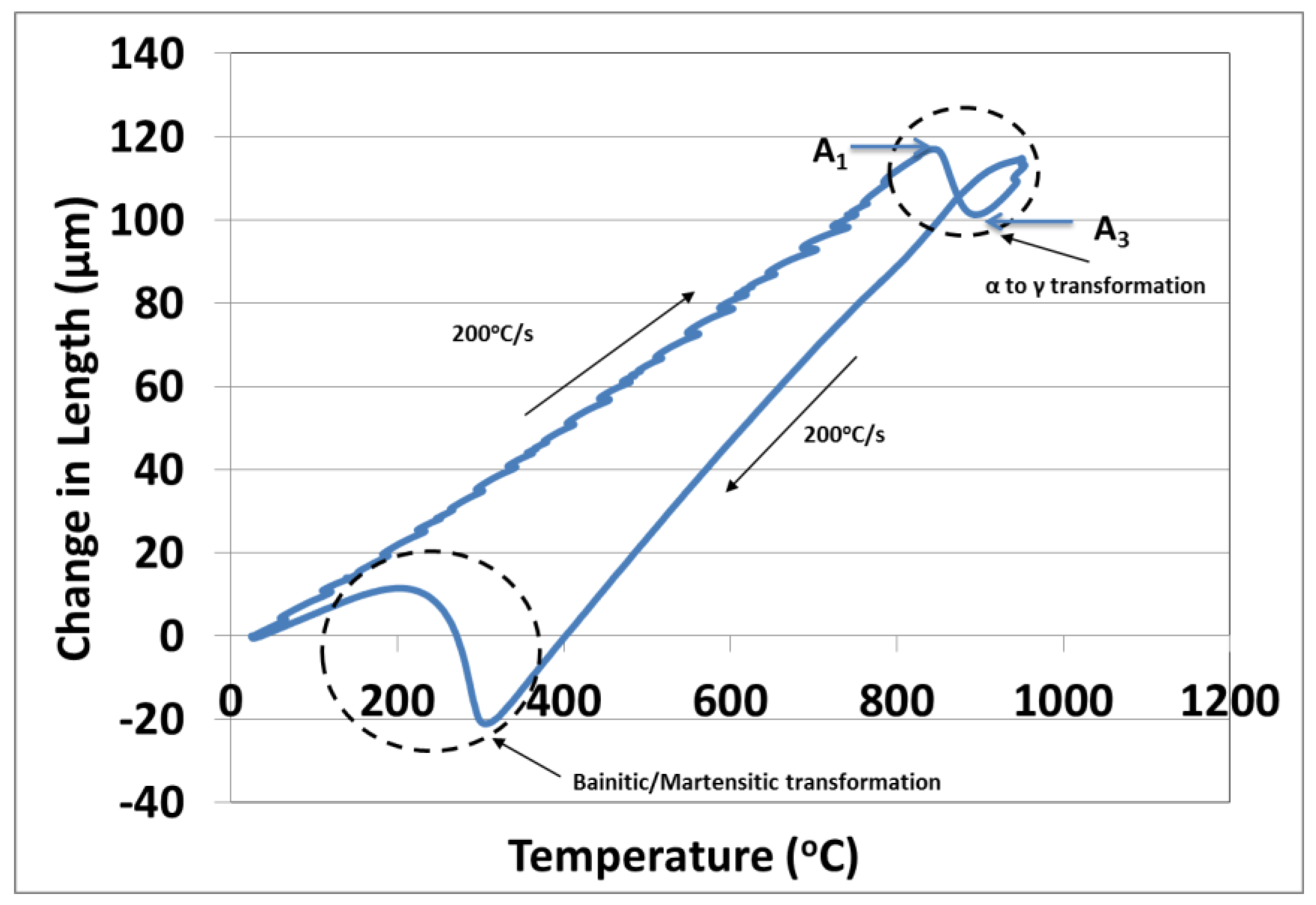
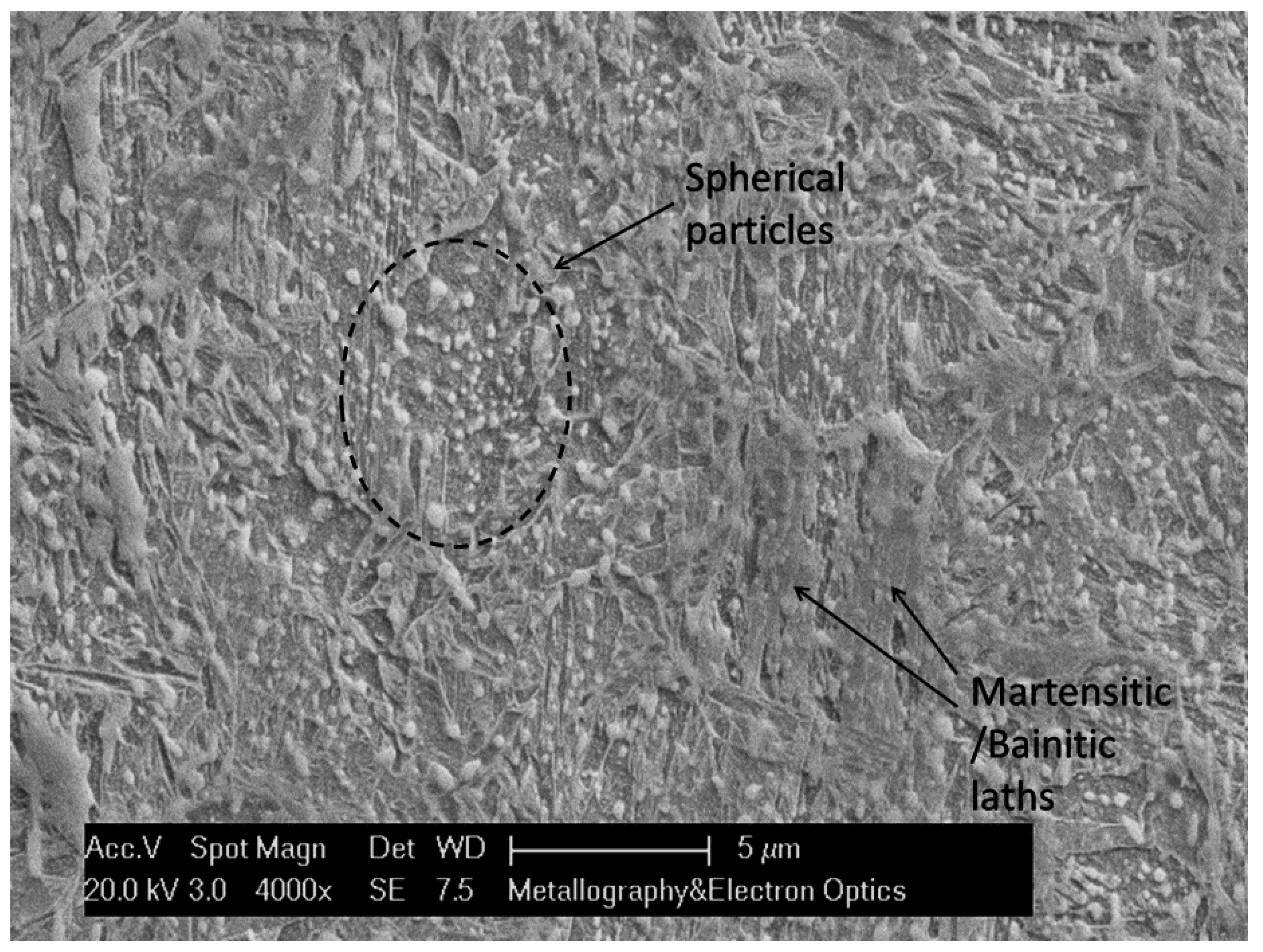
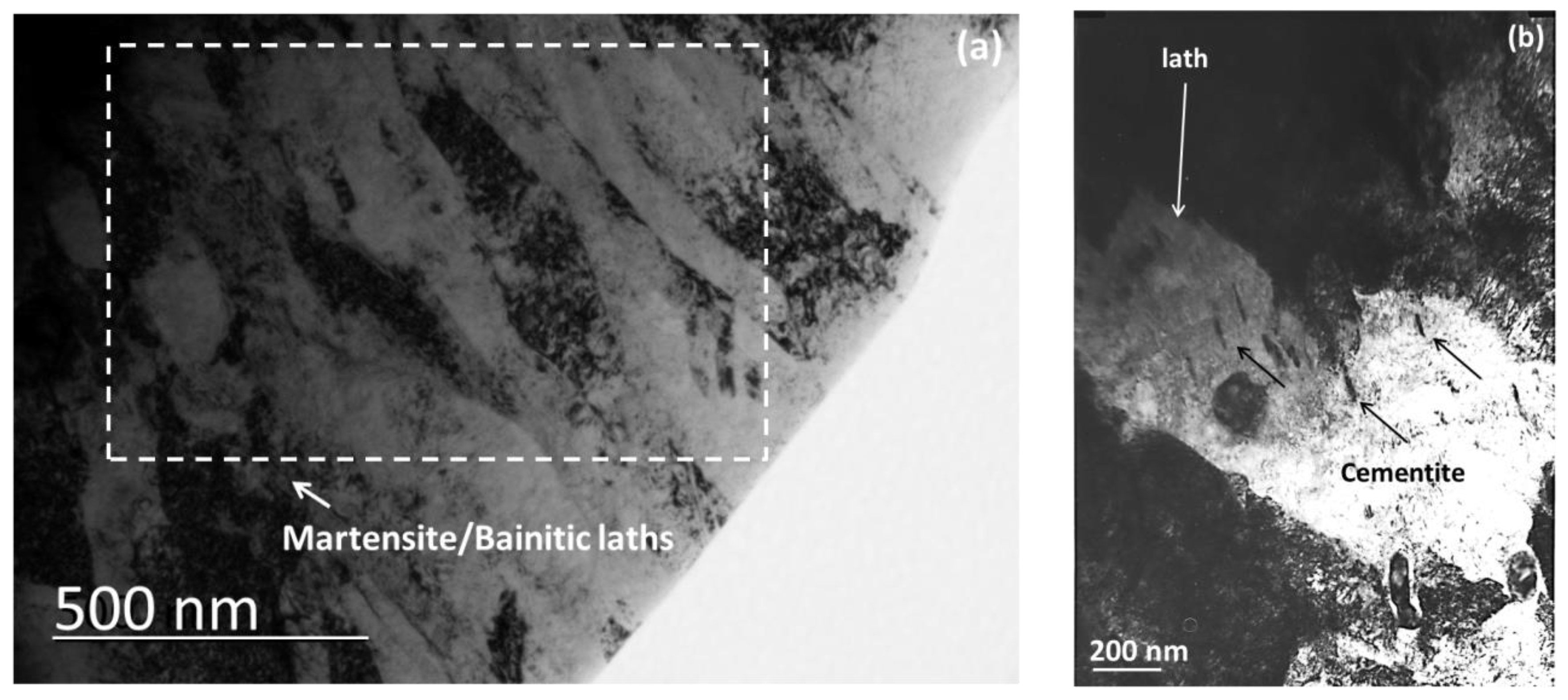
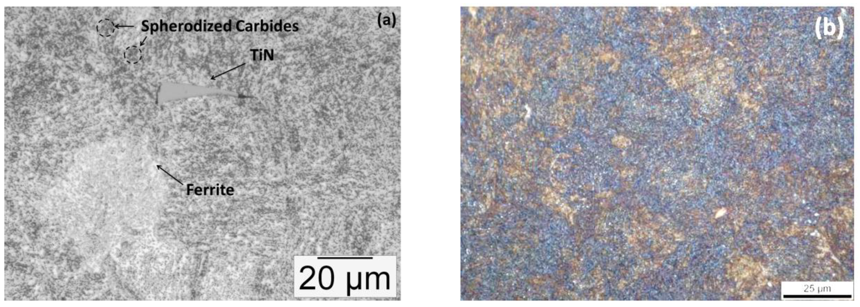
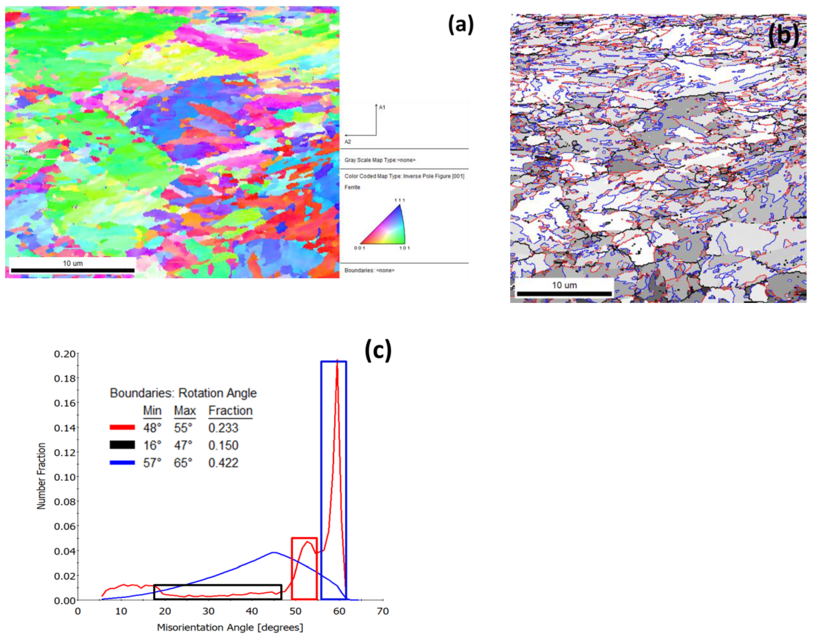
3.1. Microstructure after Ultra–Fast Heat Treatment
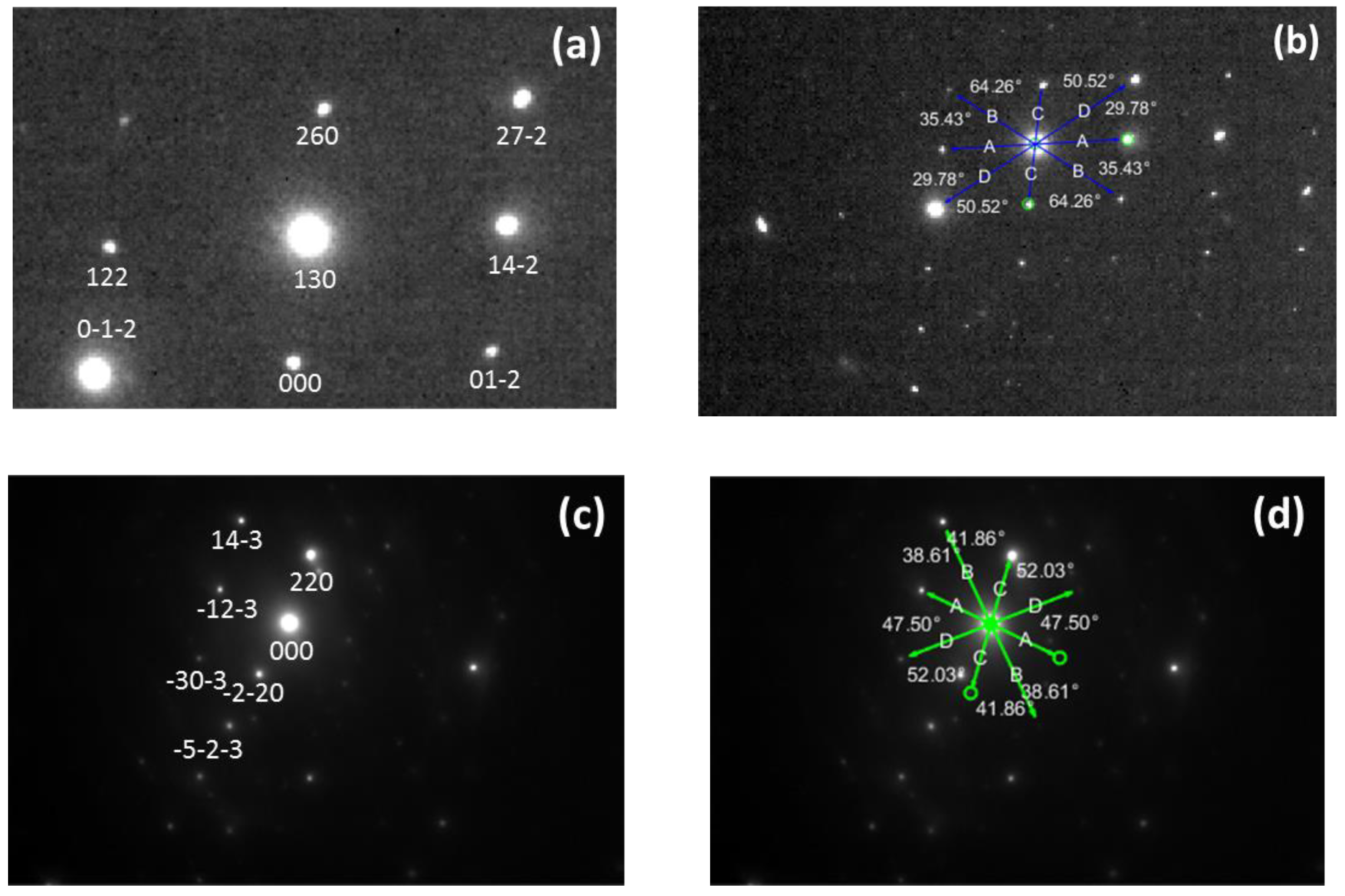
- K–S relationship exists between parent austenite and martensite.
- The misorientation associated with martensite boundaries varies from around 10° to 20°, 47–57° in case of packets and 50°–60° in case of blocks.
- Hence, it can be presumed that misorientations of 20°–47° are due to boundaries corresponding to former austenite grains [28].
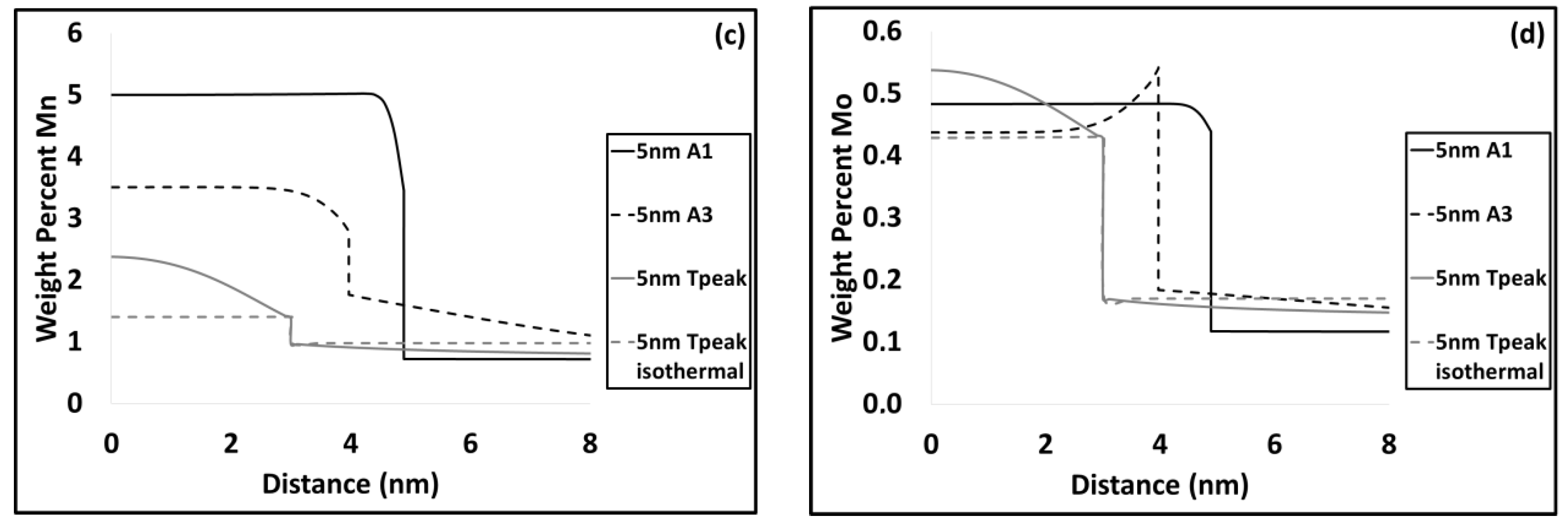
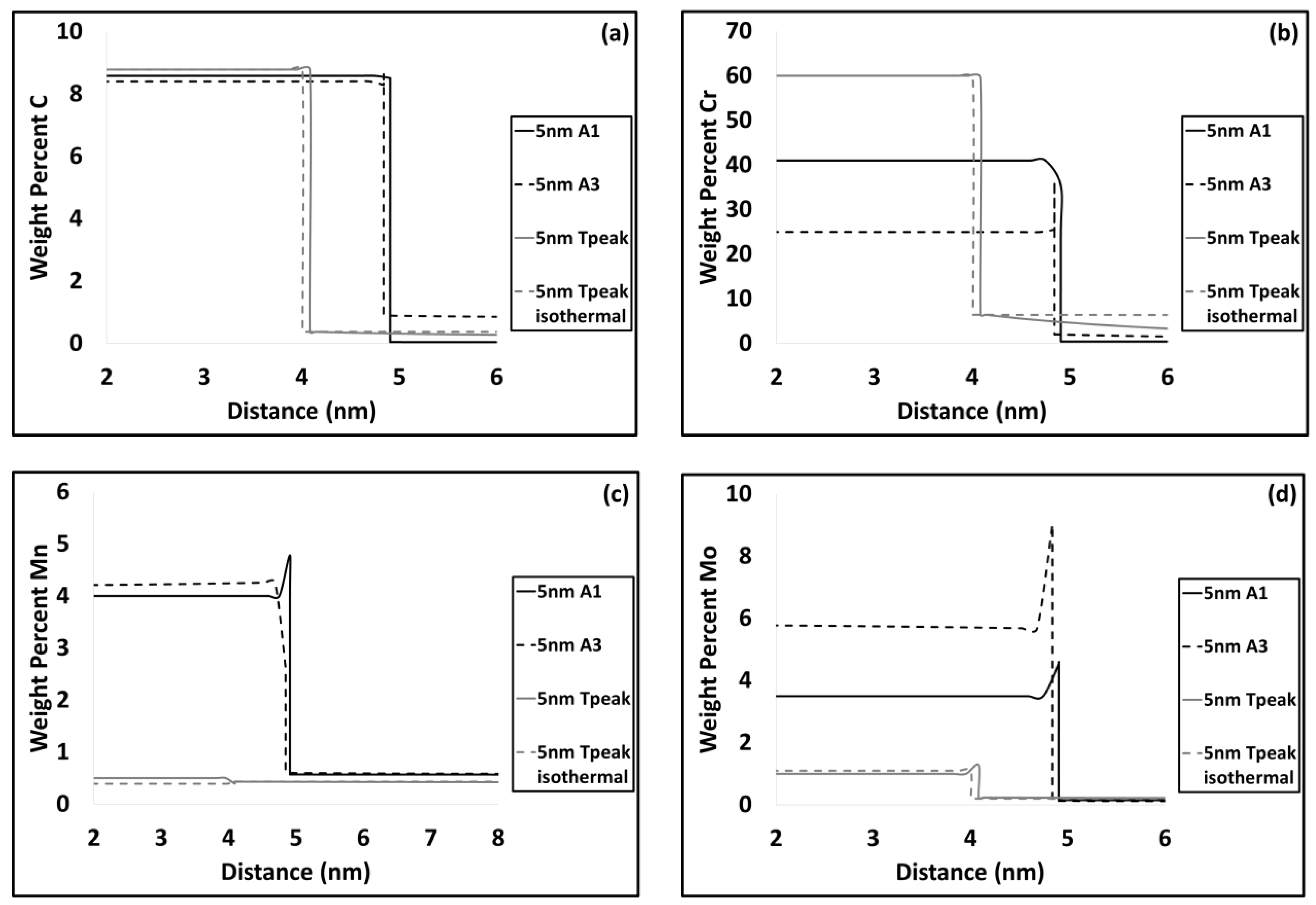
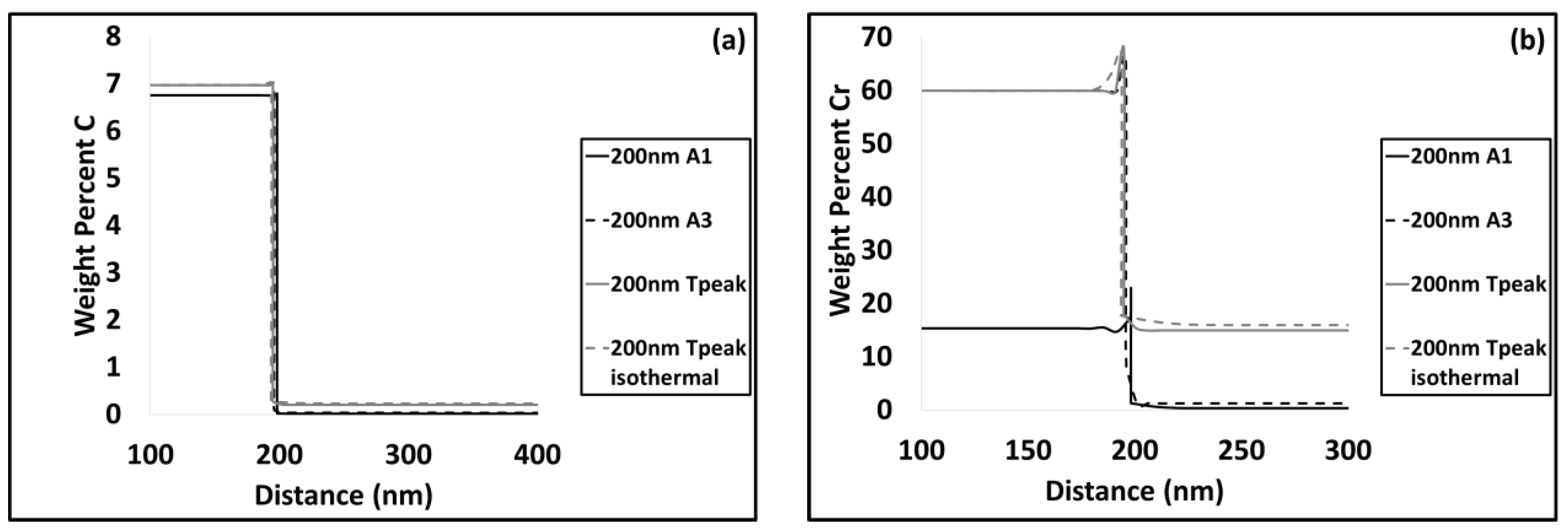
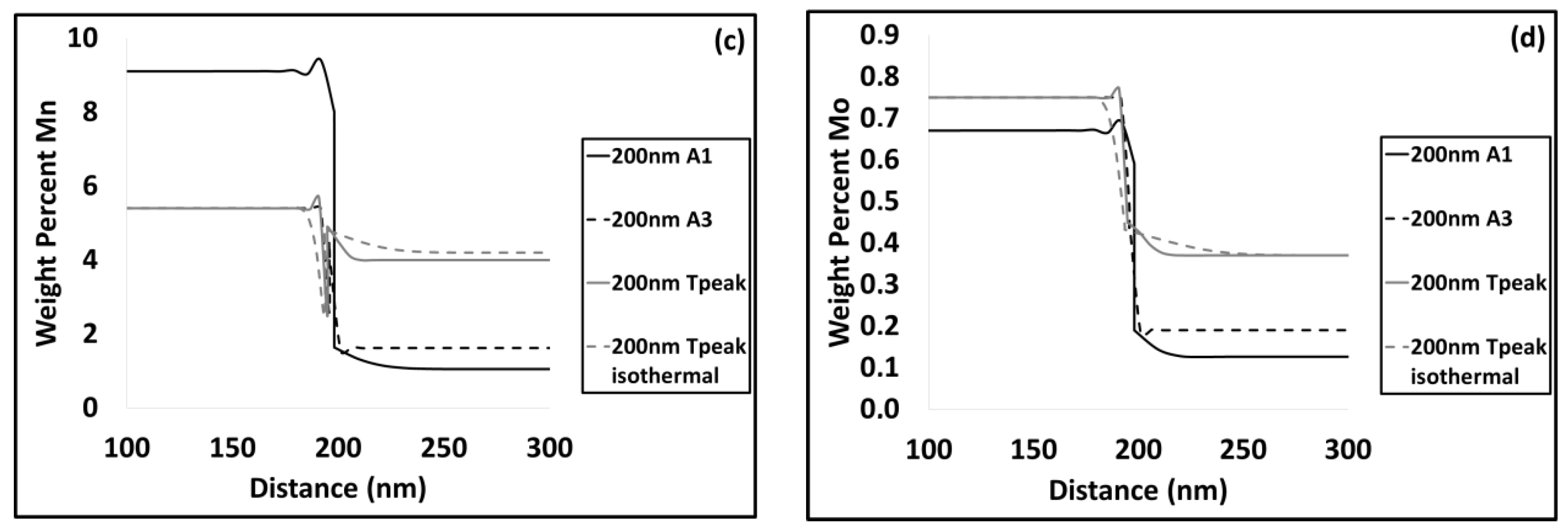
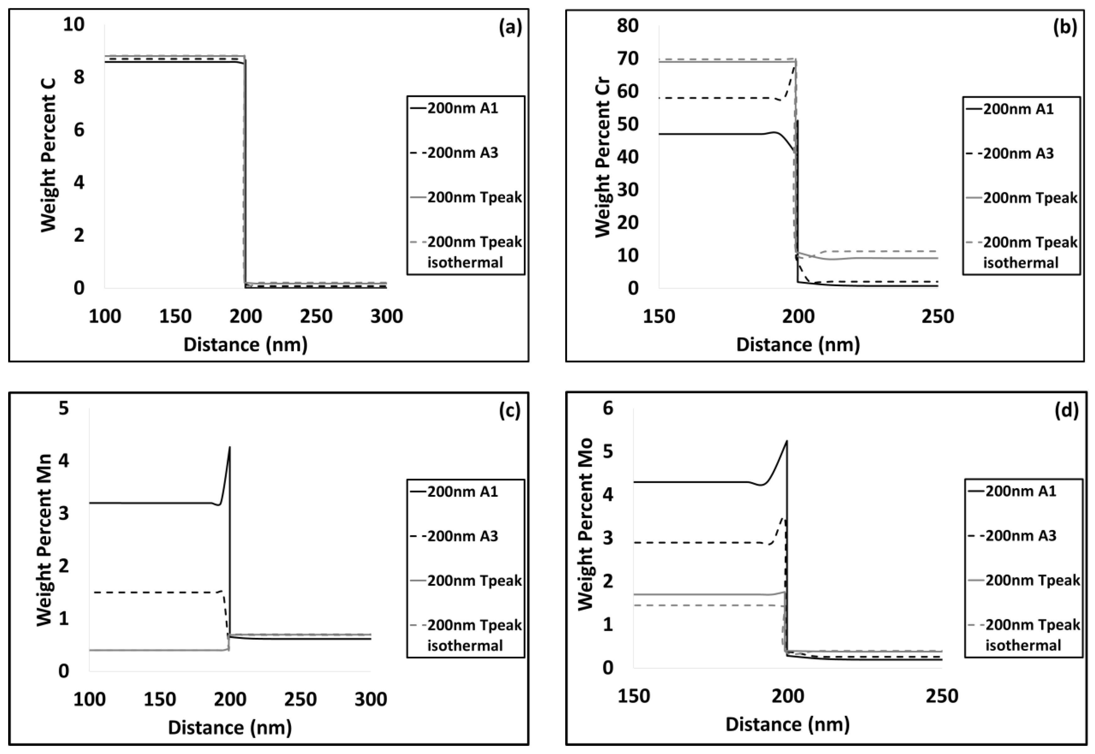
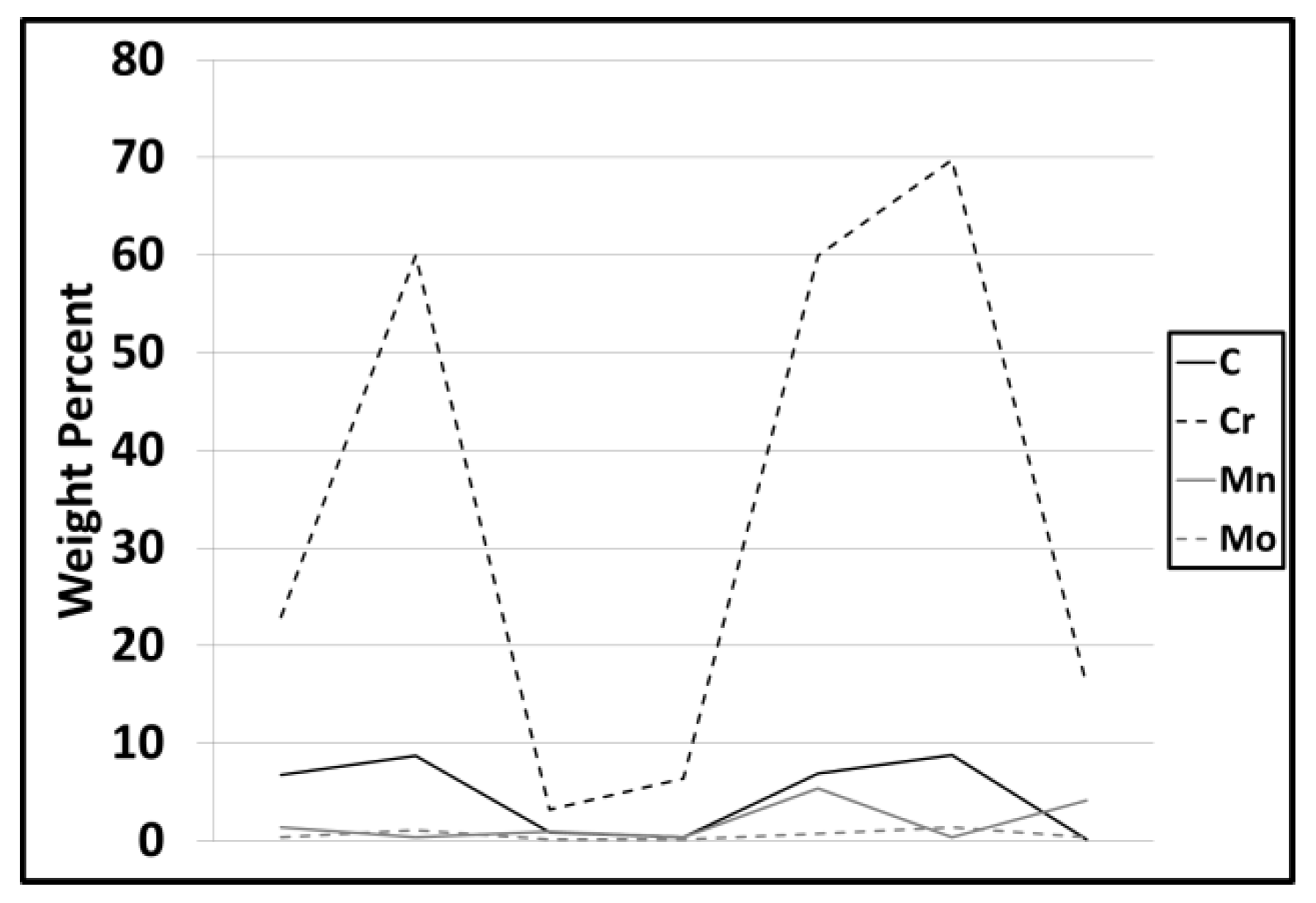
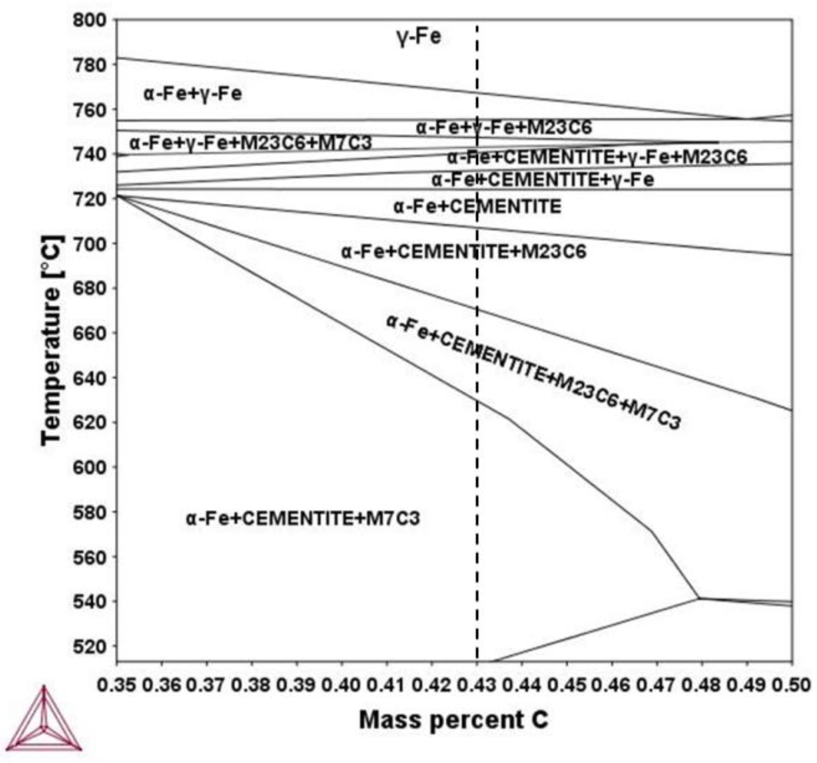
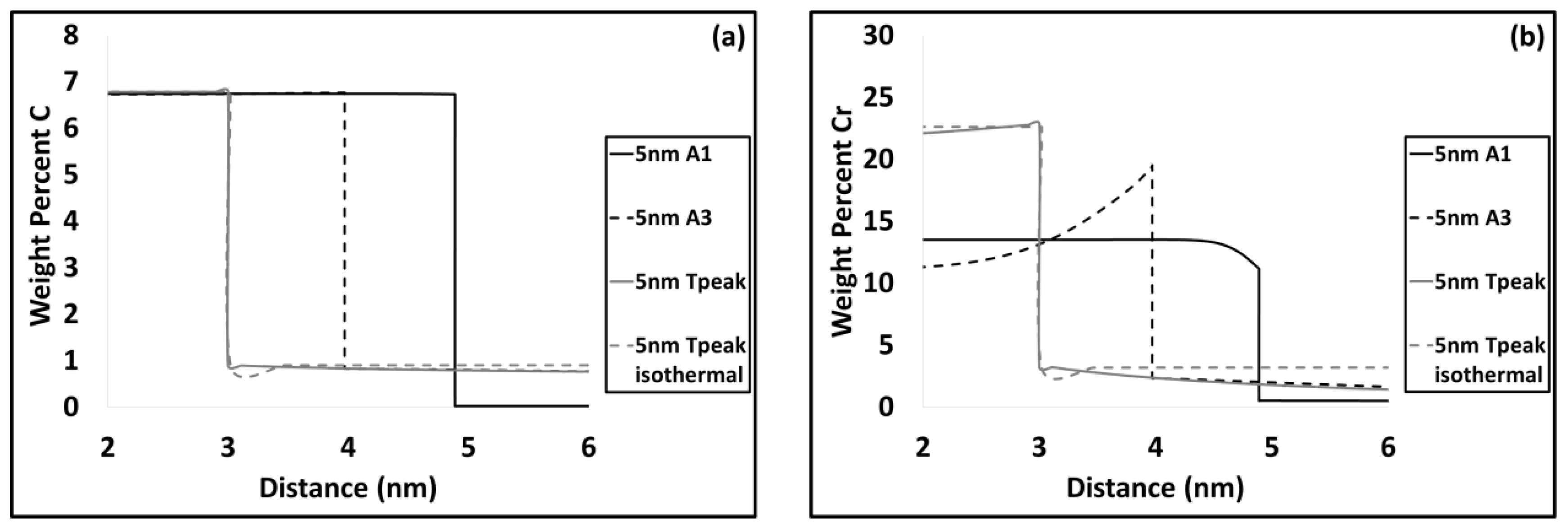
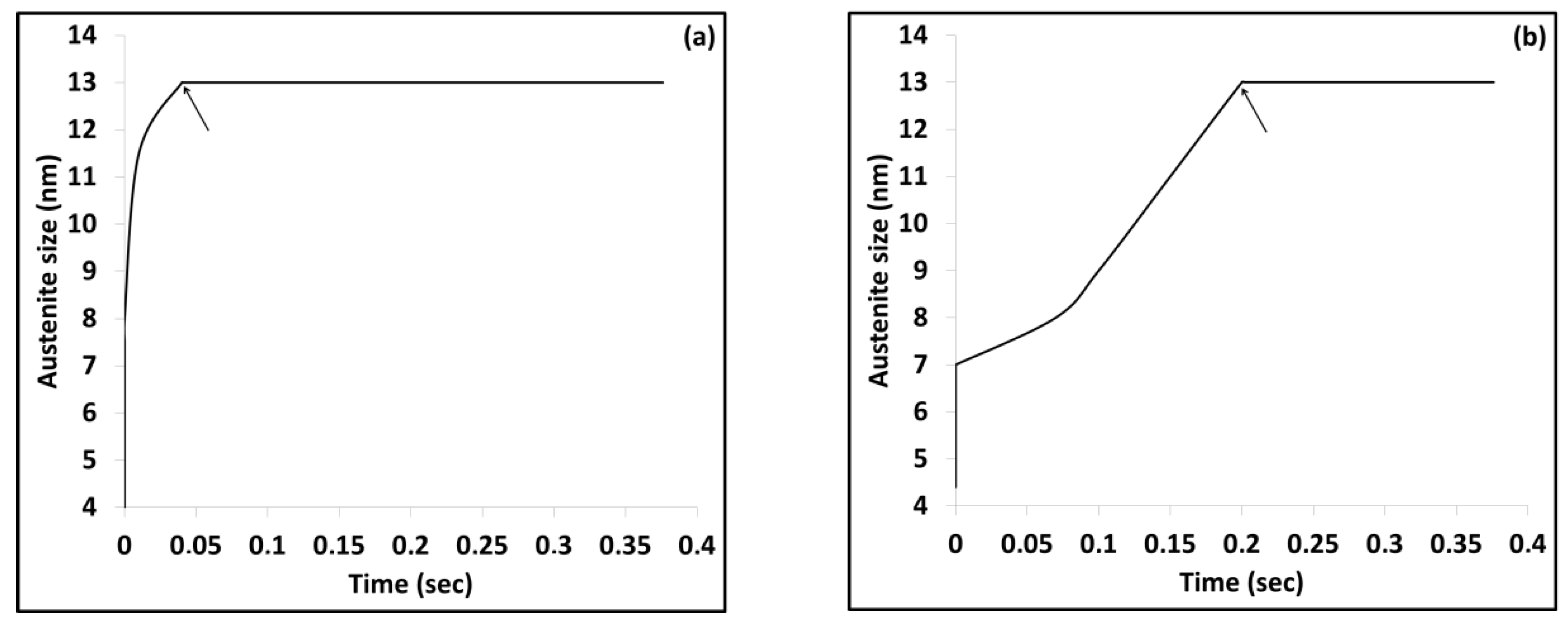
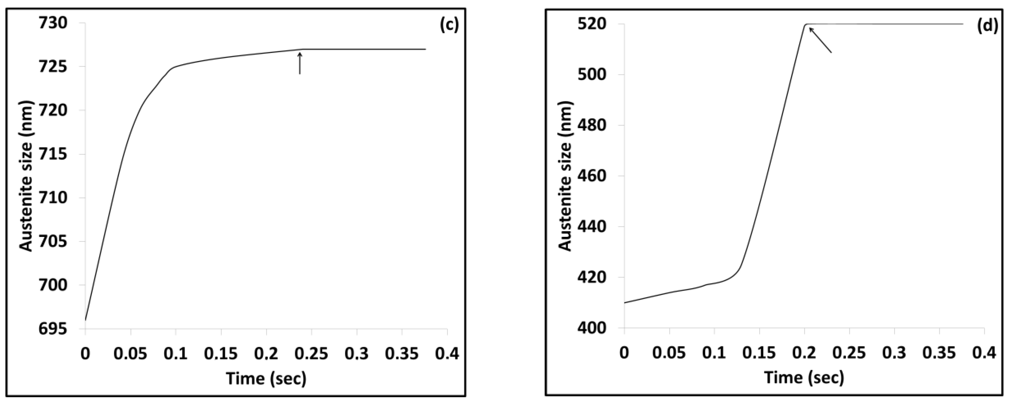
3.2. Modelling results
4. Discussion
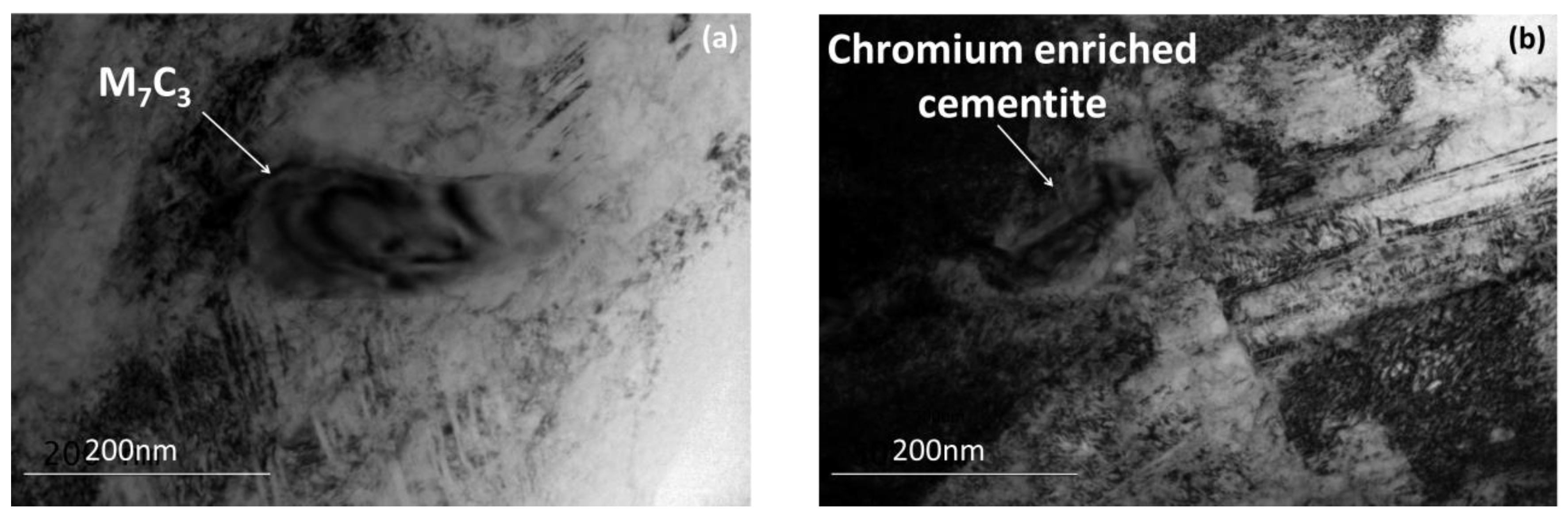
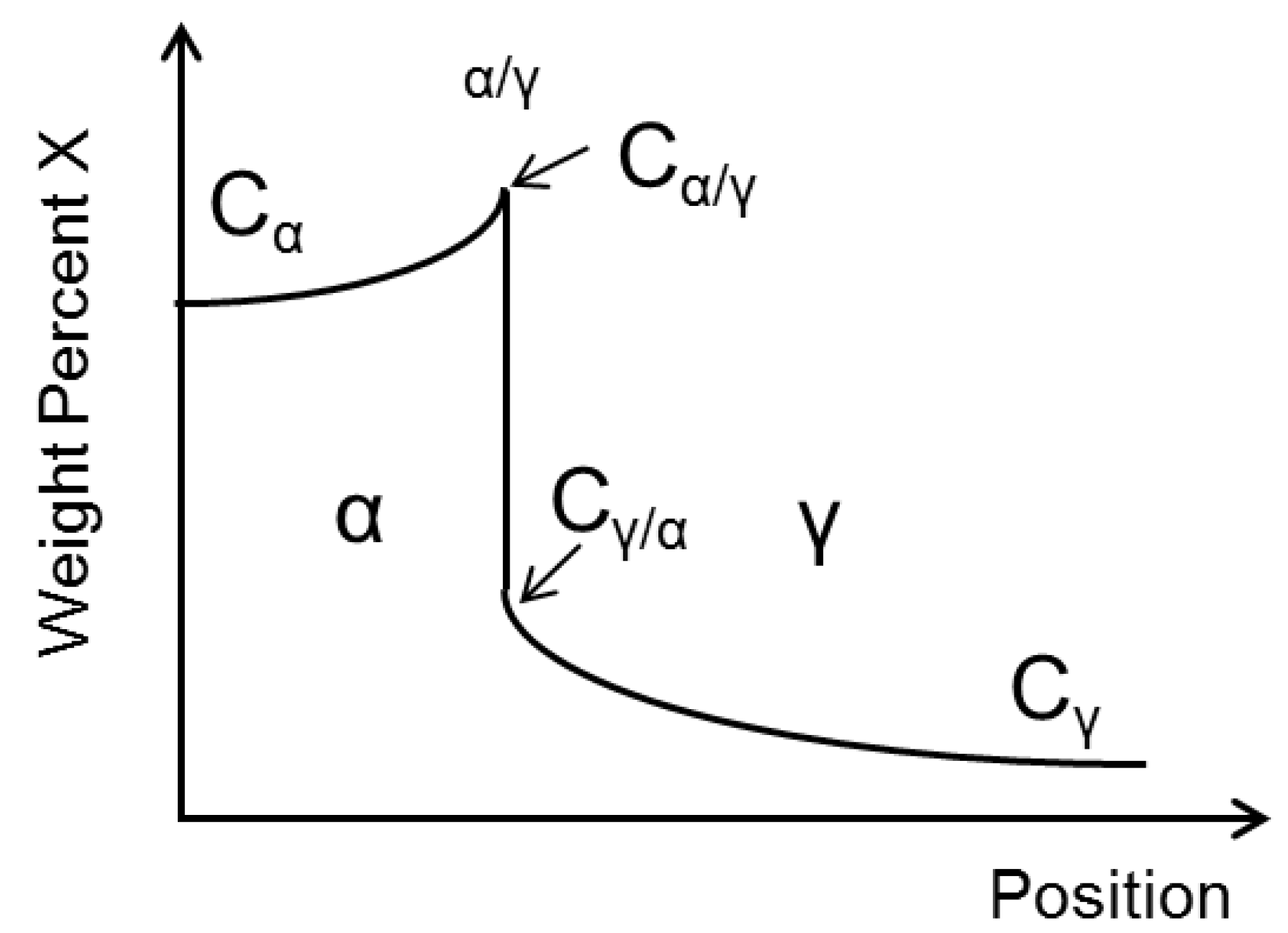
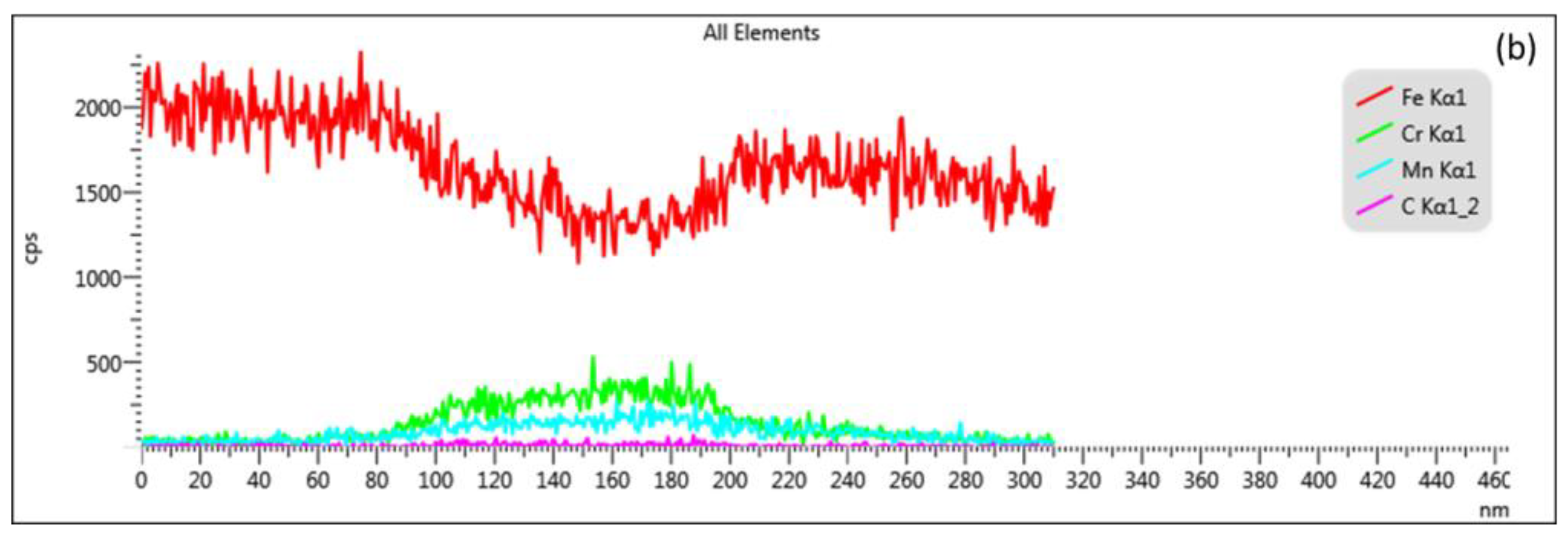
4.1. Carbide Dissolution
4.2. Austenite Formation
4.3. Phase Transformations during Quenching
5. Conclusion
Author Contributions
Funding
Acknowledgments
Conflicts of Interest
References
- Roberts, G.A.; Mehl, R.F. The mechanism and the rate of formation of austenite from ferrite-cementite aggregates. TRANS A.S.M. 1943, 31, 613–650. [Google Scholar]
- Kong, L.N.; Liu, Y.H.; Liu, J.A.; Song, Y.L.; Li, S.S.; Zhang, R.H.; Li, T.J.; Liang, Y. The influence of chromium on the pearlite-austenite transformation kinetics of the Fe–Cr–C ternary steels. J. Alloys Compd. 2015, 648, 494–499. [Google Scholar] [CrossRef]
- Speich, G.; Szirmae, A.; Richards, M. Formation of austenite from ferrite and ferrite-carbide aggregates. Trans. Metall. Soc. AIME 1969, 245, 1063–1074. [Google Scholar]
- Judd, R.R.; Paxton, H.W. Kinetics of austenite formation from a spheroidized ferrite-carbide aggregate. Trans. AIME 1968, 242, 206–215. [Google Scholar]
- Hillert, M.; Nilsson, K.; Torndahl, L.-E. Effect of alloying elements on the formation of austenite and dissolution of cementite. J. Iron Steel Inst. 1971, 209, 49–66. [Google Scholar]
- Liu, Z.K.; Agren, J. Morphology of cementite decomposition in an Fe–Cr–C alloy. Metal. Trans. A 1991, 22, 1753–1759. [Google Scholar] [CrossRef]
- Liu, Z.K.; Hoglund, L.; Jonsson, B.; Agren, J. An experimental and theoretical study of cementite dissolution in a Fe–Cr–C Alloy. Metal. Trans. A 1991, 22, 1745–1752. [Google Scholar] [CrossRef]
- Schemmann, L.; Zaefferer, S.; Raabe, D.; Friedel, F.; Mattissen, D. Alloying effects on microstructure formation of dual phase steels. Acta Mater. 2015, 95, 386–398. [Google Scholar] [CrossRef]
- Raabe, D.; Herbig, M.; Sandlöbes, S.; Li, Y.; Tytko, D.; Kuzmina, M.; Ponge, D.; Choi, P.-P. Grain boundary segregation engineering in metallic alloys: A pathway to the design of interfaces. Curr. Opin. Solid State Mater. Sci. 2014, 18, 253–261. [Google Scholar] [CrossRef]
- Goune, M.; Maugis, P.; Drillet, J. A criterion for the change from fast to slow regime of cementite dissolution in Fe–C–Mn Steels. J. Mater. Sci. Technol. 2012, 28, 728–736. [Google Scholar] [CrossRef]
- Lolla, T. Understanding Microstructure Evolution in Rapid Thermal Processing of AISI 8620 Steel. Master’s Thesis, The Ohio State University, Columbus, OH, USA, 2009. [Google Scholar]
- Cola, G. Properties of bainite nucleated by water quenching in 80 ms. In International Symposium on Steel Science, 1st; Furuhara, T., Tsuzaki, K., Eds.; Iron and Steel Institute of Japan: Tokyo, Japan, 2007; pp. 187–190. [Google Scholar]
- Lolla, T.; Alexandrov, B.; Babu, S.; Cola, G. Towards understanding the microstructure development during flash heating and cooling of steels. Presented at the International Conference on processing and manufacturing of advanced materials-THERMEC’ 09, Berlin, Germany, 25–29 August 2009. [Google Scholar]
- Lolla, T.; Cola, G.; Narayanan, B.; Alexandrov, B.; Babu, S. Development of rapid heating and cooling (flash processing) process to produce advanced high strength steel microstructures. Mater. Sci. Technol. 2011, 27, 863–875. [Google Scholar] [CrossRef]
- Holzweissig, M.J.; Lackmann, J.; Konrad, S.; Schaper, M.; Niendorf, T. Influence of short austenitization treatments on the mechanical properties of low—alloyed steels for hot forming applications. Metall. Mat. Trans. A 2015, 46A, 3199–3207. [Google Scholar] [CrossRef]
- Goulas, K. Developing Novel Heat treatments for Automotive Spring Steels: Phase Transformations, Microstructure and Performance. Doctoral Thesis, Delft University of Technology, Delft, Netherlands, 2018. [Google Scholar]
- Kaluba, W.J.; Taillard, R.; Foct, J. The bainitic mechanism of austenite formation during rapid heating. Acta Mater. 1998, 46, 5917–5927. [Google Scholar] [CrossRef]
- Cerda, F.M.C.; Goulas, C.; Sabirov, I.; Papaefthymiou, S.; Monsalve, A.; Petrov, R.H. Microstructure, texture and mechanical properties in a low carbon steel after ultrafast heating. Mater. Sci. Eng. A 2016, 672, 108–120. [Google Scholar] [CrossRef]
- Cerda, F.M.C.; Sabirov, I.; Goulas, C.; Sietsma, J.; Monsalve, A.; Petrov, R.H. Austenite formation in 0.2% C and 0.45% C steels under conventional and ultrafast heating. Mater. Des. 2017, 116, 448–460. [Google Scholar] [CrossRef]
- Papaefthymiou, S.; Goulas, C.; Cerda, F.M.C.; Geerlofs, N.; Petrov, R.H. The effect of heating rate on the microstructure of a soft-annealed medium carbon steel. Steel Res. Int. 2017, 87, 1–9. [Google Scholar] [CrossRef]
- DeKnijf, D.; Puype, A.; Föjer, C.; Petrov, R.H. The influence of ultra-fast annealing prior to quenching and partitioning on the microstructure and mechanical properties. Mater. Sci. Eng. A 2015, 627, 182–190. [Google Scholar] [CrossRef]
- Cerda, F.M.C.; Kestens, L.A.I.; Monsalve, A.; Petrov, R.H. The effect of ultrafast heating in cold-rolled low carbon steel: Recrystallization and texture evolution. Metals 2016, 6, 288. [Google Scholar] [CrossRef]
- Valdes-Tabernero, M.A.; Vercruysse, F.; Sabirov, I.; Petrov, R.H.; Monclus, M.A.; Molina-Aldareguia, J.M. Effect of ultrafast heating on the properties of the microconstituents in a low-carbon steel. Metall. Mat. Trans. A 2018, 49, 3145–3150. [Google Scholar] [CrossRef]
- Andersson, J.; Helander, T.; Höglund, L.; Shi, P.; Sundman, B. Thermo-Calc and DICTRA, computational tools for materials science. Calphad 2002, 26, 273–312. [Google Scholar] [CrossRef]
- Klinger, M. CrysTBox-Crystallographic Toolbox; Institute of Physics of the Czech Academy of Sciences: Prague, Czech, 2015. [Google Scholar]
- Zakerinia, H.; Kermanpur, A.; Najafizadeh, A. Color metallography; A suitable method for characterization of martensite and bainite in multiphase steels. Int. J. ISSI 2009, 6, 14–18. [Google Scholar]
- Lee, S.J.; Lee, Y.K. Effect of austenite grain size on martensitic transformation of a low alloy steel. Mater. Sci. Forum. 2005, 475, 3169–3172. [Google Scholar] [CrossRef]
- Karthikeyan, T.; Dash, M.; Saroja, S.; Vijayalakshmi, M. Estimation of Martensite Feature Size in a Low-Carbon alloy Steel by Microtexture Analysis of Boundaries. Micron 2015, 68, 77–90. [Google Scholar] [CrossRef] [PubMed]
- Calcagnotto, M.; Ponge, D.; Raabe, D. On the effect of manganese on grain size stability and hardenability in ultrafine grained ferrite/martensite dual-phase steels. Metall. Mat. Trans. A 2012, 43, 37–46. [Google Scholar] [CrossRef]
- Goulas, C.; Mecozzi, M.; Sietzma, J. Bainite formation in medium-carbon low-silicon spring steels accounting for chemical segregation. Metall. Mat. Trans. A 2016, 47, 3077–3087. [Google Scholar] [CrossRef]


| C | Mn | Si | P | S | Cr | Mo |
|---|---|---|---|---|---|---|
| 0.43 | 1.0 | 0.35 | 0.035 | 0.04 | 1.10 | 0.25 |
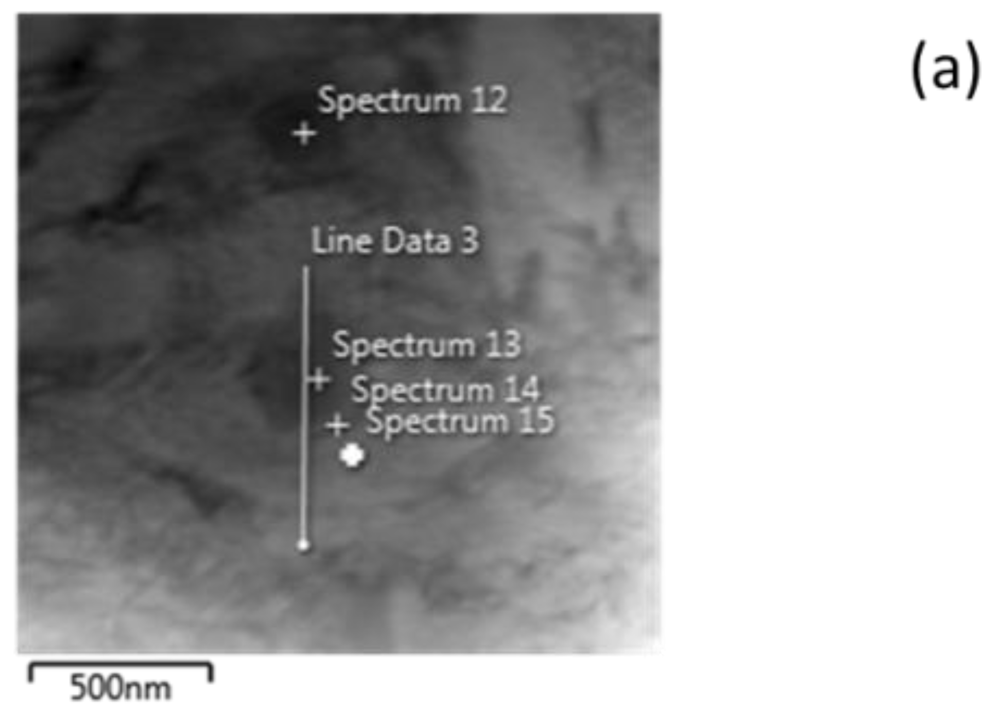
| Elements | Spectrum 12 | Spectrum 13 | Spectrum 14 | Spectrum 15 |
|---|---|---|---|---|
| C | 0.38 | 1.27 | - | - |
| Si | 0.13 | 0.10 | 0.29 | 0.38 |
| Cr | 10.79 | 14.18 | 3.29 | 0.80 |
| Mn | 5.85 | 7.66 | 3.06 | 1.15 |
| Mo | - | 0.38 | - | - |
| Fe | rest | rest | rest | rest |
| Carbide Size | Vθ/γ (m/s) | |
|---|---|---|
| 5 nm | 2.61 × 10‒6 | 3 × 10‒6 |
| 200 nm | 2.5 × 10‒6 | 1.64 × 10‒9 |
| Carbide Size | θ/γ | M7C3/γ |
|---|---|---|
| 5 nm | 13.7 nm | 0.22 μm |
| 200 nm | 1.41 μm | 1.63 μm |
© 2018 by the authors. Licensee MDPI, Basel, Switzerland. This article is an open access article distributed under the terms and conditions of the Creative Commons Attribution (CC BY) license (http://creativecommons.org/licenses/by/4.0/).
Share and Cite
Papaefthymiou, S.; Bouzouni, M.; Petrov, R.H. Study of Carbide Dissolution and Austenite Formation during Ultra-Fast Heating in Medium Carbon Chromium Molybdenum Steel. Metals 2018, 8, 646. https://doi.org/10.3390/met8080646
Papaefthymiou S, Bouzouni M, Petrov RH. Study of Carbide Dissolution and Austenite Formation during Ultra-Fast Heating in Medium Carbon Chromium Molybdenum Steel. Metals. 2018; 8(8):646. https://doi.org/10.3390/met8080646
Chicago/Turabian StylePapaefthymiou, Spyros, Marianthi Bouzouni, and Roumen H. Petrov. 2018. "Study of Carbide Dissolution and Austenite Formation during Ultra-Fast Heating in Medium Carbon Chromium Molybdenum Steel" Metals 8, no. 8: 646. https://doi.org/10.3390/met8080646
APA StylePapaefthymiou, S., Bouzouni, M., & Petrov, R. H. (2018). Study of Carbide Dissolution and Austenite Formation during Ultra-Fast Heating in Medium Carbon Chromium Molybdenum Steel. Metals, 8(8), 646. https://doi.org/10.3390/met8080646