Precipitation Hardening on Mechanical and Corrosion Properties of Extruded Mg10Gd Modified with Nd and La
Abstract
:1. Introduction
2. Materials and Methods
3. Results and Discussion
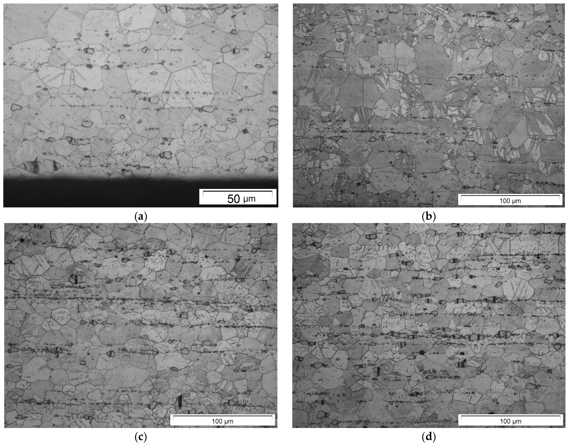
3.1. Initial Mechanical Properties and the Influence of Heat Treatments on Microstructure
3.2. Heat Treatment on Mechanical Properties: Hardness and Bending Strength
3.3. Heat Treatment and Crack Propagation
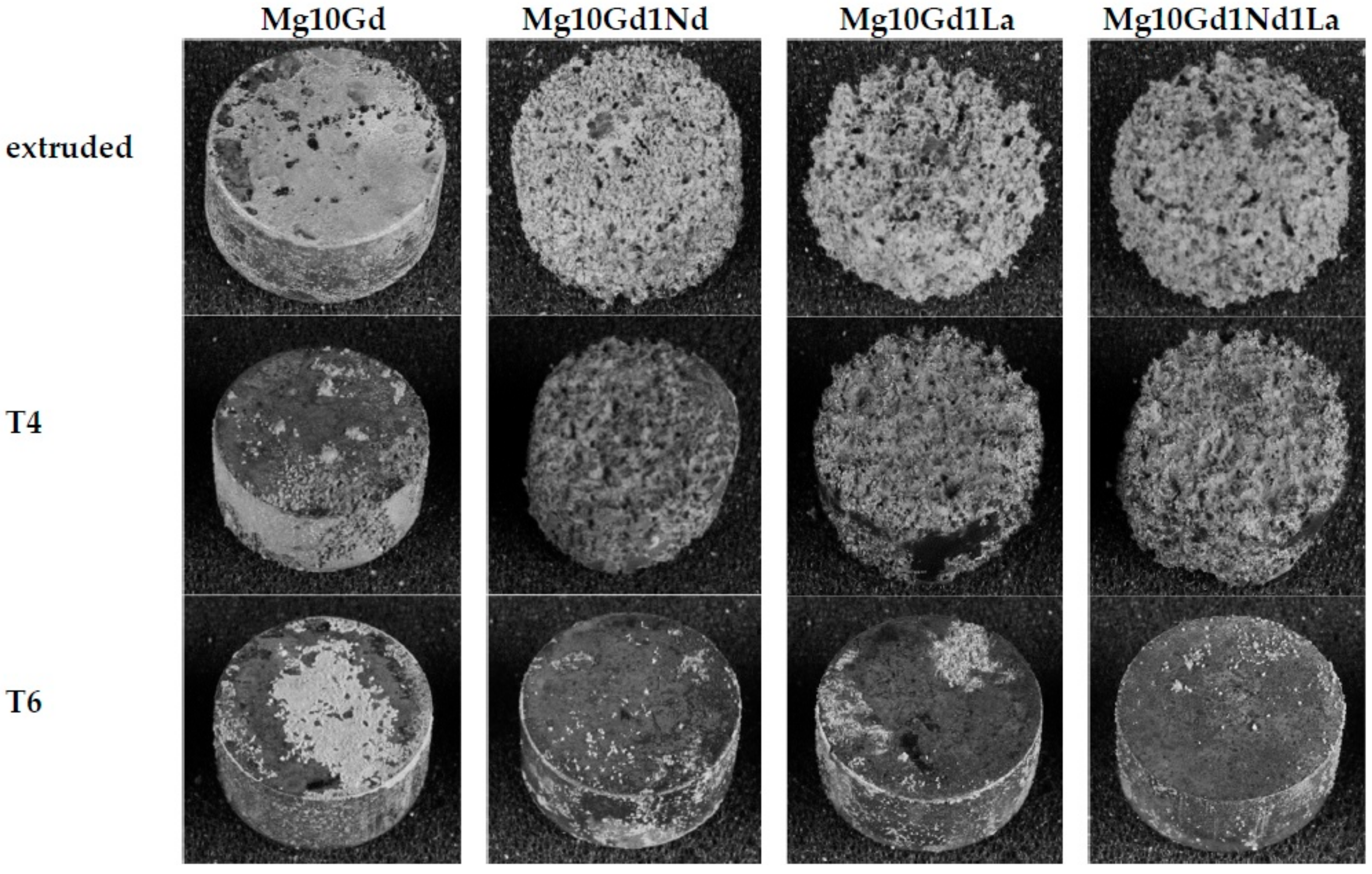
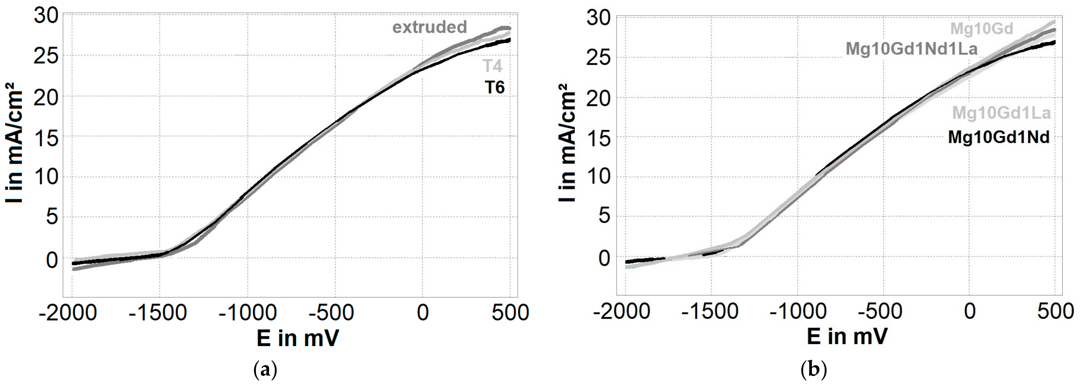
3.4. Heat Treatment and Corrosion
4. Conclusions
- Nd and/or La increases tensile and bending yield strength significantly, but due to brittle secondary phases, it hardly improves the maximum strength.
- The volume fraction and particle size of secondary phases increase with increasing alloying elements.
- Alloys containing La appear less ductile.
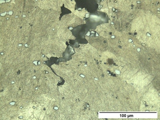
- Crack propagation in binary Mg10Gd is mostly driven by twinning.
- The increased amount and size of secondary phases by the addition of Nd and/or La seems to suppress twinning, but on the other hand, the crack initiation and propagation is caused by these brittle and coarse secondary phases—so precipitation hardening could not improve fracture toughness.
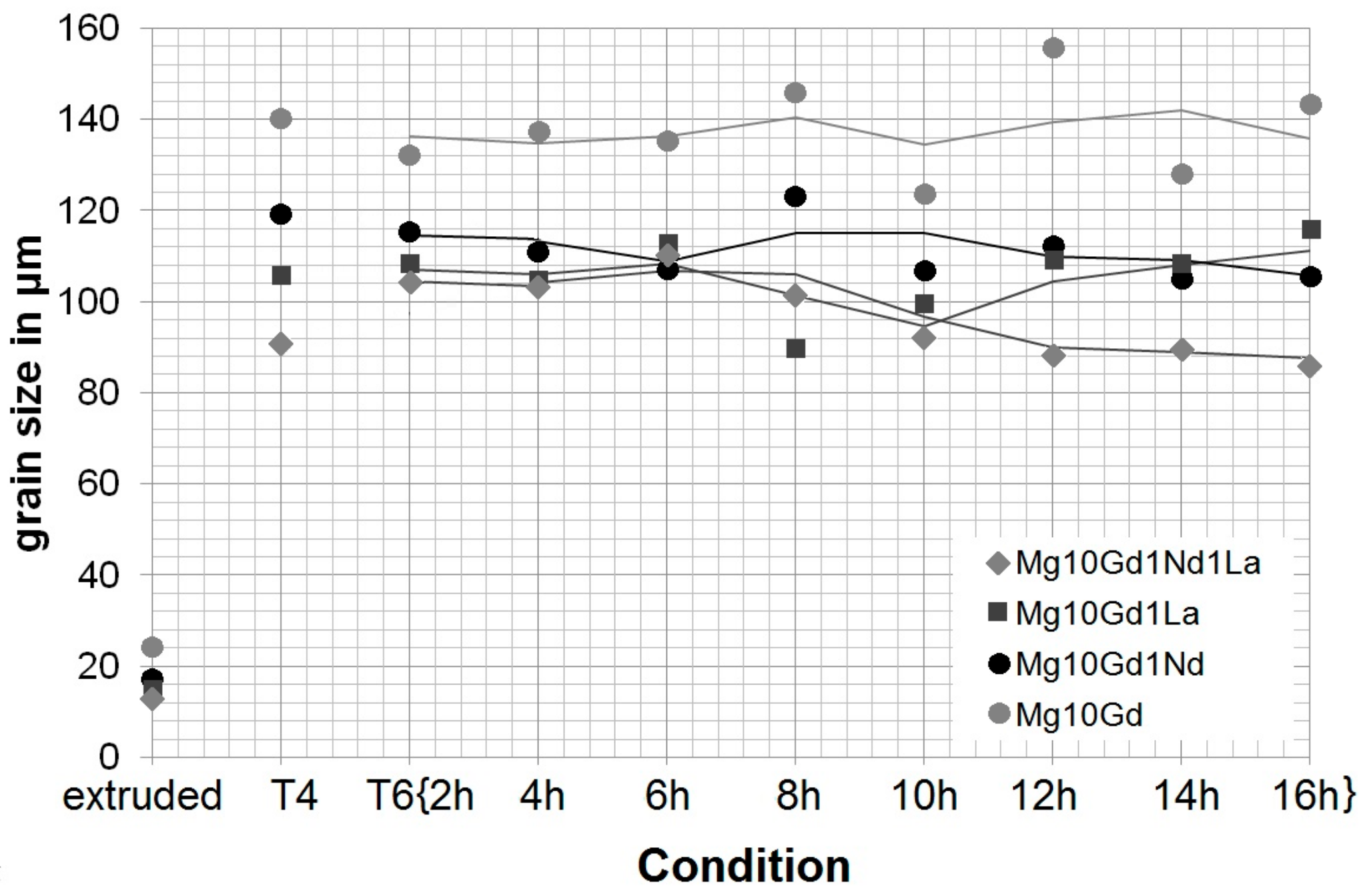
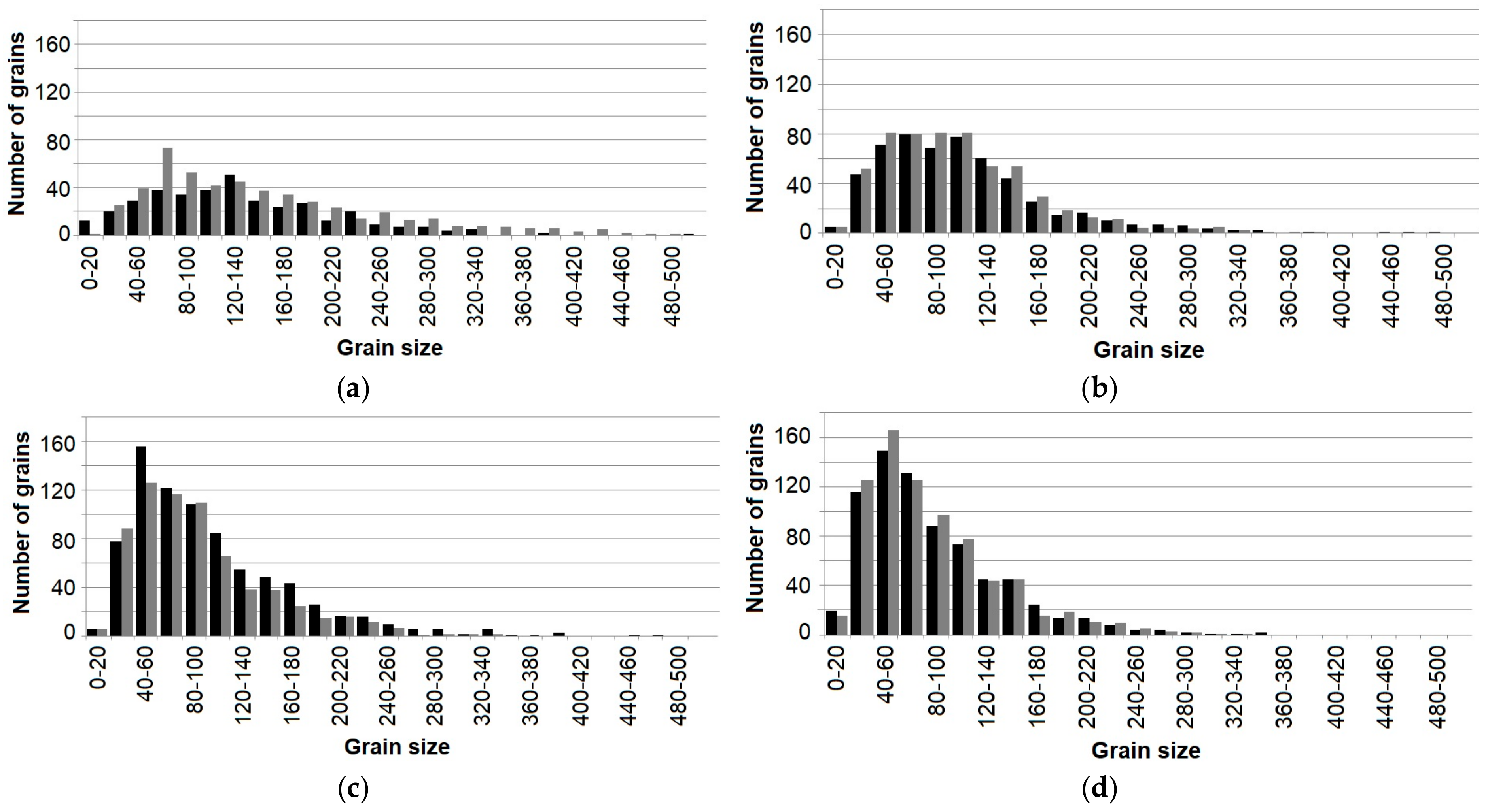
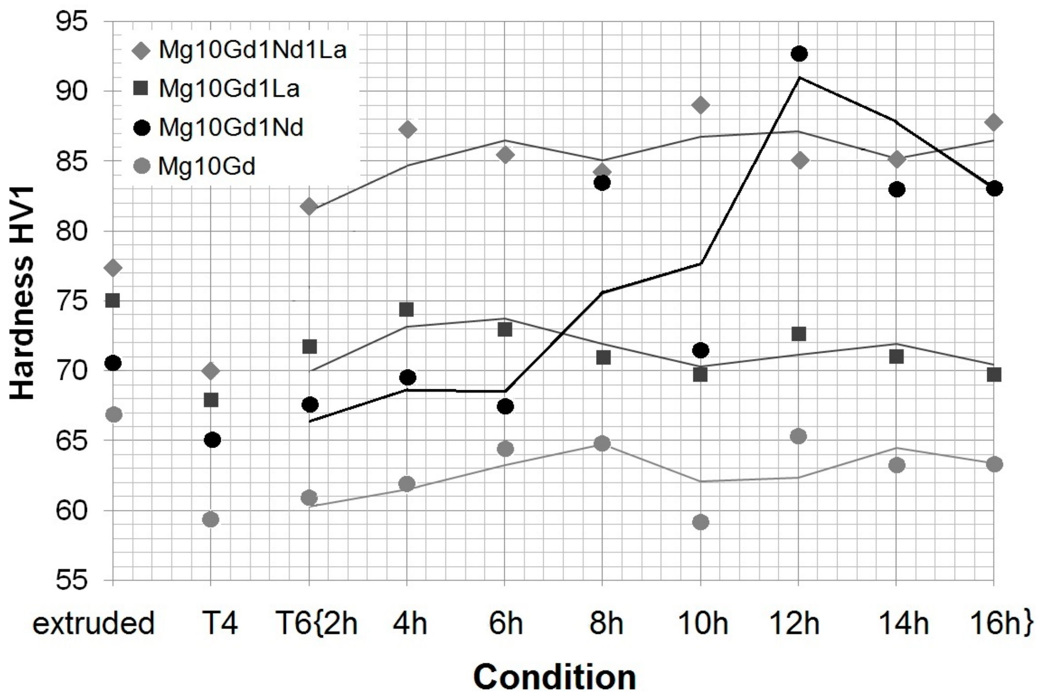
- Heat treatment causes strong grain growth—with the addition of alloying elements, the grain size stays smaller, in alloys with Nd precipitation hardening occurs—but at the expense of ductility. Particles still act in a brittle manner and influence crack growth.
- Even though the extruded material shows the smallest grain size, the corrosion rates in immersion show (apart from Mg10Gd) the highest values, due to the coarse precipitates and especially when alloyed with La.
- T6 shows the lowest corrosion rate in immersion, but very high pitting factors, apart from Mg10Gd1Nd, where the overall highest pitting resistivity is found. A pitting factor of one indicates a dense uniform corrosion layer.
- A strong correlation between the corrosion rate and the pitting factor occurs in immersion tests. When the corrosion rate is high, the pitting factor is decreased.
- There seems to be no trend in polarization tests among the alloys and the heat treatment condition.
- Corrosion morphology in polarization is more uniform where pitting factors around two are found.
- La is not a useful substitute for Nd regarding mechanical properties and corrosion behavior.
Author Contributions
Funding
Acknowledgments
Conflicts of Interest
References
- Rokhlin, L.L. Magnesium Alloys Containing Rare Earth Elements—Structure and Properties; Taylor & Francis: London, UK, 2003; ISBN 9780415284141. [Google Scholar]
- Hort, N.; Huang, Y.; Fechner, D.; Störmer, M.; Blawert, C.; Witte, F.; Vogt, C.; Drücker, H.; Willumeit, R.; Kainer, K.U.; et al. Magnesium alloys as implant materials—Principles of property design for Mg-RE alloys. Acta Biomater. 2010, 6, 1714–1725. [Google Scholar] [CrossRef] [PubMed]
- Mirza, F.A.; Chen, D.L. Fatigue of rare-earth containing magnesium alloys: A review. Fatigue Fract. Eng. Mater. Struct. 2014, 37, 831–853. [Google Scholar] [CrossRef]
- Maier, P.; Mendis, C.L.; Wolff, M.; Hort, N. Crack Propagation under Bending in Cast Mg10-GdxNd-T4 Alloys. In Magnesium Technology 2014; The Minerals, Metals & Materials Society Series; Alderman, M., Manuel, M.V., Hort, N., Neelameggham, N.R., Eds.; Springer: Cham, Switzerland, 2014; pp. 77–82. ISBN 978-1-118-88816-2. [Google Scholar]
- Maier, P.; Mendis, C.L.; Wolff, M.; Hort, N. Twinning assisted crack propagation of Magnesium-Rare Earth casting and wrought alloys under bending. Mater. Sci. Forum 2015, 828–829, 311–317. [Google Scholar] [CrossRef]
- Maier, P.; Richter, A.; Tober, G.; Hort, N. Effect of grain size and structure, solid solution elements, precipitates and twinning on nanohardness of Mg-RE alloys. Mater. Sci. Forum 2013, 765, 491–495. [Google Scholar] [CrossRef]
- Hay, J.L.; Agee, P. Mapping the Mechanical Properties of Alloyed Magnesium (AZ 61). In Magnesium Technology 2013; The Minerals, Metals & Materials Society Series; Hort, H., Mathaudhu, S.N., Neelameggham, N.R., Alderman, M., Eds.; Springer: Cham, Switzerland, 2013; pp. 329–332. ISBN 9781118605523. [Google Scholar]
- Hampl, M.; Blawert, C.; Silsa Campos, M.R.; Hort, N.; Peng, Q.; Kainer, K.U.; Schmid-Fetzer, R. Thermodynamic assessment and experimental study of Mg-Gd alloys. J. Alloys Compd. 2013, 581, 166–177. [Google Scholar] [CrossRef]
- Peng, Q.; Ning, M.; Hui, L. Gadolinium solubility and precipitate identification in Mg-Gd binary alloy. J. Rare Earths 2012, 30, 1064–1068. [Google Scholar] [CrossRef]
- Schmid-Fetzer, R.; Gröbner, J.; Kozlov, A.; Hampl, M.; Easton, M.A.; Zhu, S.M.; Gibson, M.A.; Nie, J.F. Thermodynamics of phase formation in Mg-La-Ce-Nd alloys. In Magnesium Technology 2013; The Minerals, Metals & Materials Society Series; Hort, H., Mathaudhu, S.N., Neelameggham, N.R., Alderman, M., Eds.; Springer: Cham, Switzerland, 2013; pp. 243–248. ISBN 9781118605523. [Google Scholar]
- Silva, M.; Scharnagl, B.; Blawert, C.; Kainer, K.U. Improving Corrosion Resistance of Mg10Gd Alloy. Mater. Sci. Forum 2013, 765, 673–677. [Google Scholar] [CrossRef] [Green Version]
- Willumeit, R.; Möhring, A.; Feyerabend, F. Optimization of Cell Adhesion on Mg Based Implant Materials by Pre-Incubation under Cell Culture Condition. Int. J. Mol. Sci. 2014, 15, 7639–7650. [Google Scholar] [CrossRef] [PubMed]
- Ding, Y.; Wen, C.; Hodgson, P.; Li, Y. Effects of alloying elements on the corrosion behavior and biocompatibility of biodegradable magnesium alloys: A review. J. Mater. Chem. B 2014, 2, 1912–1933. [Google Scholar] [CrossRef]
- Zhang, J.; Zhang, D.; Tian, Z.; Wang, J.; Liu, K.; Lu, H.; Tang, D.; Meng, J. Microstructures, tensile properties and corrosion behavior of die-cast Mg–4Al-based alloys containing La and/or Ce. Mater. Sci. Eng. A 2008, 489, 113–119. [Google Scholar] [CrossRef]
- Maier, P.; Gentzsch, L.; Hort, H. Voltammetric studies of extruded pure Mg in different electrolytes and its corrosion morphology. In Magnesium Technology 2017; Solanki, K., Orlov, D., Singh, A., Neelameggham, N.R., Eds.; Springer: Cham, Switzerland, 2017; pp. 429–437. ISBN 978-3-319-52391-0. [Google Scholar]
- Maier, P.; Bechly, M.; Hort, H. Solution heat treatment on mechanical properties and corrosion of extruded Mg5Gd compared to pure Mg. In Proceedings of the Materials Science and Technology 2017 (MS&T17), Pittsburgh, PA, USA, 8–12 October 2017; pp. 76–83. [Google Scholar]
- Argade, G.R.; Panigrahia, S.K.; Mishra, R.S. Effects of grain size on the corrosion resistance of wrought magnesium alloys containing neodymium. Corros. Sci. 2012, 58, 145–151. [Google Scholar] [CrossRef]
- Aung, N.N.; Zhou, W. Effect of grain size and twins on corrosion behaviour of AZ31B magnesium alloy. Corros. Sci. 2010, 52, 589–594. [Google Scholar] [CrossRef]








| Alloy | TYS (MPa) | UTS (MPa) | Elongation (%) | CYS (MPa) | UCS (MPa) | CS (%) | HV1 |
|---|---|---|---|---|---|---|---|
| Mg10Gd | 131.4 ± 2.2 | 248.9 ± 2.7 | 22.9 ± 2.8 | 133.7 ± 0.4 | 399.2 ± 10.2 | 26.1 ± 1.3 | 66.8 ± 3.5 |
| Mg10Gd1Nd | 138.2 ± 3.3 | 256.0 ± 4.1 | 17.3 ± 1.2 | 148.9 ± 5.7 | 397.5 ± 14.2 | 16.8 ± 1.2 | 70.6 ± 6.3 |
| Mg10Gd1La | 149.2 ± 8.4 | 248.0 ± 3.9 | 17.0 ± 3.7 | 149.4 ± 1.1 | 395.8 ± 12.5 | 18.4 ± 0.5 | 75.0 ± 4.6 |
| Mg10Gd1Nd1La | 165.4 ± 0.9 | 253.4 ± 2.2 | 12.2 ± 1.1 | 161.2 ± 1.3 | 393.4 ± 23.3 | 13.0 ± 2.1 | 77.4 ± 4.9 |
| Alloy | Gd | Nd | La | Grain Size | Secondary Phases |
|---|---|---|---|---|---|
| Mg10Gd | 9.7 | - | - | 23.9 ± 11.8 | Mg5Gd |
| Mg10Gd1Nd | 9.8 | 0.88 | - | 16.8 ± 8.3 | Mg5(Gd,Nd) |
| Mg10Gd1La | 9.7 | - | 0.83 | 14.7 ± 6.5 | Mg5(Gd,La) |
| Mg10Gd1Nd1La | 9.5 | 0.88 | 0.89 | 13.2 ± 5.6 | Mg5(Gd,Nd,La) |
| Alloy Condition | Mg10Gd | Mg10Gd1Nd | Mg10Gd1La | Mg10Gd1Nd1La |
|---|---|---|---|---|
| extruded | 15.1 | 3.5 | 2.0 | 2.1 |
| T4 | 13.8 | 6.2 | 6.1 | 3.7 |
| T6 | 88.8 | 1.0 | 75.0 | 82.9 |
| Alloy Condition | Mg10Gd | Mg10Gd1Nd | Mg10Gd1La | Mg10Gd1Nd1La |
|---|---|---|---|---|
| extruded | 0.28/2.2 | 0.36/2.1 | 0.33/1.9 | 0.27/1.9 |
| T4 | 0.30/2.0 | 0.29/2.1 | 0.31/1.9 | 0.24/1.6 |
| T6 | 0.34/2.0 | 0.27/1.8 | 0.32/2.0 | 0.29/1.8 |
© 2018 by the authors. Licensee MDPI, Basel, Switzerland. This article is an open access article distributed under the terms and conditions of the Creative Commons Attribution (CC BY) license (http://creativecommons.org/licenses/by/4.0/).
Share and Cite
Maier, P.; Bechly, M.; Mendis, C.L.; Hort, N. Precipitation Hardening on Mechanical and Corrosion Properties of Extruded Mg10Gd Modified with Nd and La. Metals 2018, 8, 640. https://doi.org/10.3390/met8080640
Maier P, Bechly M, Mendis CL, Hort N. Precipitation Hardening on Mechanical and Corrosion Properties of Extruded Mg10Gd Modified with Nd and La. Metals. 2018; 8(8):640. https://doi.org/10.3390/met8080640
Chicago/Turabian StyleMaier, Petra, Maximilian Bechly, Chamini L. Mendis, and Norbert Hort. 2018. "Precipitation Hardening on Mechanical and Corrosion Properties of Extruded Mg10Gd Modified with Nd and La" Metals 8, no. 8: 640. https://doi.org/10.3390/met8080640
APA StyleMaier, P., Bechly, M., Mendis, C. L., & Hort, N. (2018). Precipitation Hardening on Mechanical and Corrosion Properties of Extruded Mg10Gd Modified with Nd and La. Metals, 8(8), 640. https://doi.org/10.3390/met8080640


