Article

Microstructure and Properties of Friction Stir Welded 2219 Aluminum Alloy under Heat Treatment and Electromagnetic Forming Process

1
State Key Laboratory of Materials Processing and Die & Mould Technology, School of Materials Science and Engineering, Huazhong University of Science and Technology, Wuhan 430074, China
2
State Key Laboratory of Advanced Design and Manufacturing for Vehicle Body, Hunan University, Changsha 410082, China
3
Changzheng Machinery Factory, China Aerospace Science and Technology Corporation, Chengdu 610100, China
*
Author to whom correspondence should be addressed.
Metals 2018, 8(5), 305; https://doi.org/10.3390/met8050305
Submission received: 25 March 2018 / Revised: 21 April 2018 / Accepted: 21 April 2018 / Published: 28 April 2018
(This article belongs to the Special Issue Modern Aerospace Materials)

Abstract

:
Among available processing technologies of heat-treatable aluminum alloys such as the 2219 aluminum alloy, the use of both friction stir welding (FSW) as joining technology and electromagnetic forming (EMF) for plastic formation technology have obvious advantages and successful applications. Therefore, significant potential exists for these processing technologies, both of which can be used on the 2219 aluminum alloy, to manufacture large-scale, thin-wall parts in the astronautic industry. The microstructure and mechanical properties of 2219 aluminum alloy under a process which compounded FSW, heat treatment, and EMF were investigated by means of a tensile test as well as via both an optical microscope (OM) and scanning electron microscope (SEM). The results show that the reduction of strength, which was caused during the FSW process, can be recovered effectively. This can be accomplished by a post-welding heat treatment composed of solid solution and aging. However, ductility was still reduced after heat treatment. Under the processing technology composed of FSW, heat treatment, and EMF, the forming limit of the 2219 aluminum alloy decreased distinctly due to the poor ductility of the welding joint. A ribbon pattern was found on the fractured surface of welded 2219 aluminum alloy after EMF treatment, which was formed due to the banded structure caused by the FSW process. Because of the effects of induced eddy current in the EMF process, the material fractured, forming a unique structure which manifested as a molten surface appearance under SEM observation.

Graphical Abstract

1. Introduction

2219 aluminum alloy is a suitable material for manufacturing large-scale, thin-wall parts in the astronautic industry, such as the cryogenic fuel tank of launch vehicles, thanks to its characteristics of good weldability, corrosion stability as well as its superior qualities in specific strength and thermal stability [1,2]. The manufacturing process of 2219 aluminum alloy is composed of welding, heat treatment, and plastic formation [3]. Friction stir weld (FSW) can effectively minimize the thermal input and reduce the peak temperature compared with conventional welding technologies [4]. A welding joint with fewer welding defects and higher performance can be obtained through the solid bonding achieved by FSW [5]. A heat treatment composed of solid solution and aging can produce a dispersive distribution of precipitated phase, which can bring a remarkable improvement in the mechanical properties of 2219 aluminum alloy [6]. Simultaneously, as a high-velocity forming method, electromagnetic forming (EMF) can increase the forming limit of material and improve the performance of the workpieces compared with conventional quasi-static forming technologies [7,8]. Thus, in the astronautic industry, there is significant potential for the application of these processing technologies in the manufacturing of large-scale, thin-wall parts [9].
FSW technology, which can create solid bonding through the frictional effects of the tool shoulder and the stirring effect of the pin, has been widely applied in the manufacture for large-scale parts of aluminum alloys. Extensive research has been conducted as to the influence of processing parameters and the plastic flow behavior during FSW treatment. After FSW treatment, the microstructure and properties of the welding joint on the butt-welded 2219 aluminum alloy sheets are predominantly affected by rotation speed, welding speed, pin geometry, and the post-welding heat treatment [5,10]. Because of the penetrating depth which occurs during the FSW process, the surface material is extruded by the tool shoulder and flows downwards under the stirring effect of pin. As the surface material flows into the plastic zone, a banded structure known as an onion ring is formed as a result of the interaction between the flowing material and the in situ material [11,12]. According to previous studies, through a proper post-weld annealing treatment, the mechanical properties of welded material can be recovered effectively and may be even superior to the full-annealed base metal [13].
The studies of heat treatment on heat-treatable aluminum alloys have largely focused on solid solution and aging treatment. A dispersive distribution of precipitated phase can be achieved in the matrix of 2219 aluminum alloy during heat treatment. The secondary phases precipitated during aging treatment, which is mainly composed of Al2Cu, play an important role in the aging strengthening of 2219 aluminum alloy [14]. The precipitating behavior of the secondary phase can be greatly affected by plastic deformation. With a proper deformation degree, a more dispersive distribution of secondary phase can be achieved, which can further improve the strength of the 2219 aluminum alloy [15]. Plastic deformation also leads to an acceleration in the precipitating rate and changes the optimum parameters of the aging treatment [16].
EMF technology is a high velocity-forming technology, which is achieved by applying a pulse electromagnetic field on the formed material. During the EMF process, the velocity of deformation can exceed 300 m/s. Under a high strain rate, the microstructure evolves differently from the quasi-static deformation, such as the adiabatic shear bands which can be found in the split Hopkinson pressure bar test [17]. The dynamic response is also affected by the heat treatment condition [18], which can be attributed to the influences of precipitated phase. Moreover, the behavior of plastic deformation is also affected by the coupled multi-field, which is compounded by the electromagnetic field, induced eddy current, and high-strain field [19,20]; this can include a change in the movement and pinning of dislocation and the distribution of the low-angle grain boundary. A reduction of flow stress is observed when plastic deformation is electrically assisted [21], which is strongly associated with a rise in the material’s temperature, caused by the Joule effect of electricity [22].
Although the 2219 aluminum alloy proceeds through the entire processing flow of FSW, heat treatment, and EMF, there are many different evolutions in microstructure and properties which hardly appear in the conventional process. The thermal effect and the plastic flow during FSW treatment causes an expediting of precipitation during heat treatment, and the inhomogeneous structure of the welding joint will reduce the formability of 2219 aluminum alloy during the EMF process [9]. Thus, it is essential to study the cooperative effects of FSW, heat treatment, and EMF for the application of the 2219 aluminum alloy in the astronautic industry.
This paper investigates the microstructure and properties of the 2219 aluminum alloy under different compound technologies of FSW and heat treatment through a tensile test and SEM to study the interaction and the optimum combination of FSW and heat treatment. Then, samples of 2219 aluminum alloy under both optimum compound technology and heat treatment are processed by EMF treatment. The forming characteristics and the fracture appearance of 2219 aluminum alloy are discussed to study the influences of FSW treatment on the forming behavior of 2219 aluminum alloy during the EMF process.

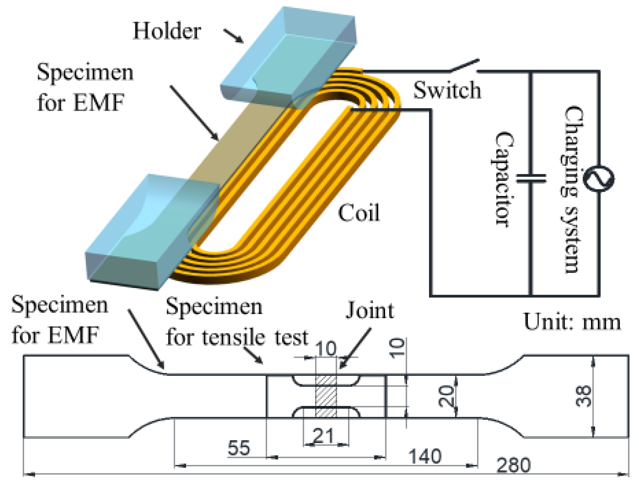
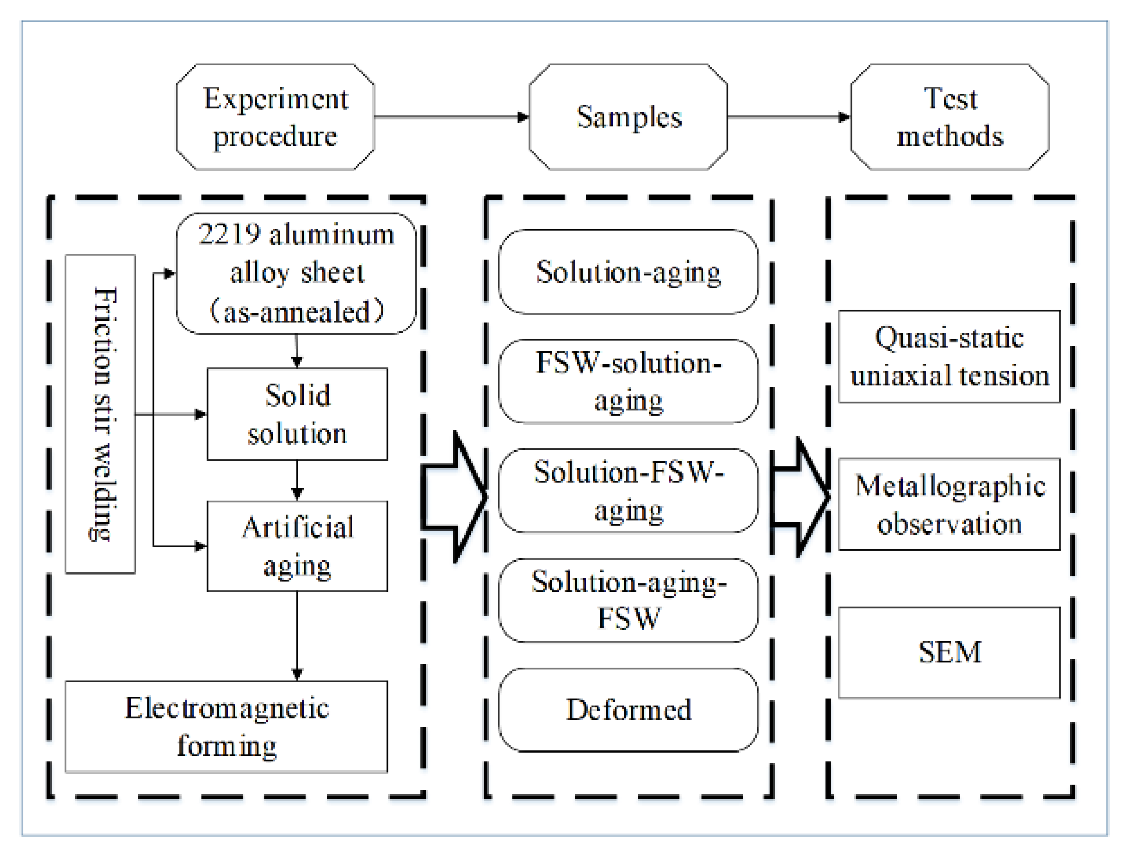
2. Materials and Methods

The materials used in this work were fully annealed 2219 Al alloy sheets with a thickness of 2 mm and the chemical component which is depicted in Table 1. By constituting the main precipitated phase known as Al2Cu in the matrix, Cu was the predominant strengthening element in the 2219 aluminum alloy [23]; Mn could increase the thermal stability of alloy by forming T phase (Al20Cu2Mn3), which was the main dispersoid in 2 × 24 aluminum alloys with a rod-like shape [14].
In the FSW process, a tool with 10 mm shoulder diameter, 1.7 mm pin diameter, and 1.7 mm pin length was used, and the schematic of the FSW process is shown in Figure 1. The FSW was performed with a rotation rate of 1200 rpm and a welding speed of 200 mm/min, which was perpendicular to the rolling direction of sheet. The shoulder penetrating depth was adjusted at 2 mm without tilting angle while the FSW was performed. The heat treatment included a solid solution treatment of 535 °C for 40 min as well as water quenching and artificial aging of 180 °C for 6 h.
A schematic of the EMF process is shown in Figure 2, with the demonstration of samples which were used in the EMF process and the tensile test. Both samples were designed according to Chinese standard (GB/T 228-2002) and the main dimensions are illustrated in Figure 2. The EMF system used was HMF-30/213/150, the maximum energy storage was 96 kJ, the maximum charging voltage was 30 kV, the capacitance used for energy storage was 216 μF, and the inductance of the coil was 15.48 μH. The normal direction of sheet was along with the axial direction of coil to obtain a maximal variation of magnetic flux. During the EMF process, the capacitor was charged by the charging system, and a pulse electromagnetic field was generated by a discharge through the coil.
The processing route is shown in Figure 3. On the basis of the heat treatment of solid solution and aging, the FSW was performed on the samples under different heat treatment conditions including as-annealed, as-solid-solution, and as-aged to obtain various compound technologies of the FSW and heat treatment. The microstructure and properties of these samples were compared by means of a tensile test, OM, and SEM to study the interaction and the optimum compound technology of the FSW and heat treatment. The EMF treatment was performed on the 2219 aluminum alloy samples, which were processed under the optimal compound technology of FSW and heat treatment. Then, the microstructure and properties were studied through forming characteristics and fracture morphology.
The tensile test was performed on an AG-100kN testing machine which is produced at SHIMADZU CORPORARION in Kyoto, Japan with a tensile speed of 1 mm/min at room temperature; for each of the conditions, three samples were used for testing. The samples were polished and etched with Keller’s reagent to reveal the microstructure for the OM observation on the welding joint. The OM observation was performed on a VHX-1000C optical microscope VHX-1000C optical microscope which was produced at KEYENCE CORPORARION in Osaka, JAPAN. The fracture surface was observed using JSM-7600F FESEM which was produced at JEOL Ltd. in Tokyo, JAPAN.

3. Results and Discussion

3.1. Compound Technologies of FSW and Heat Treatment

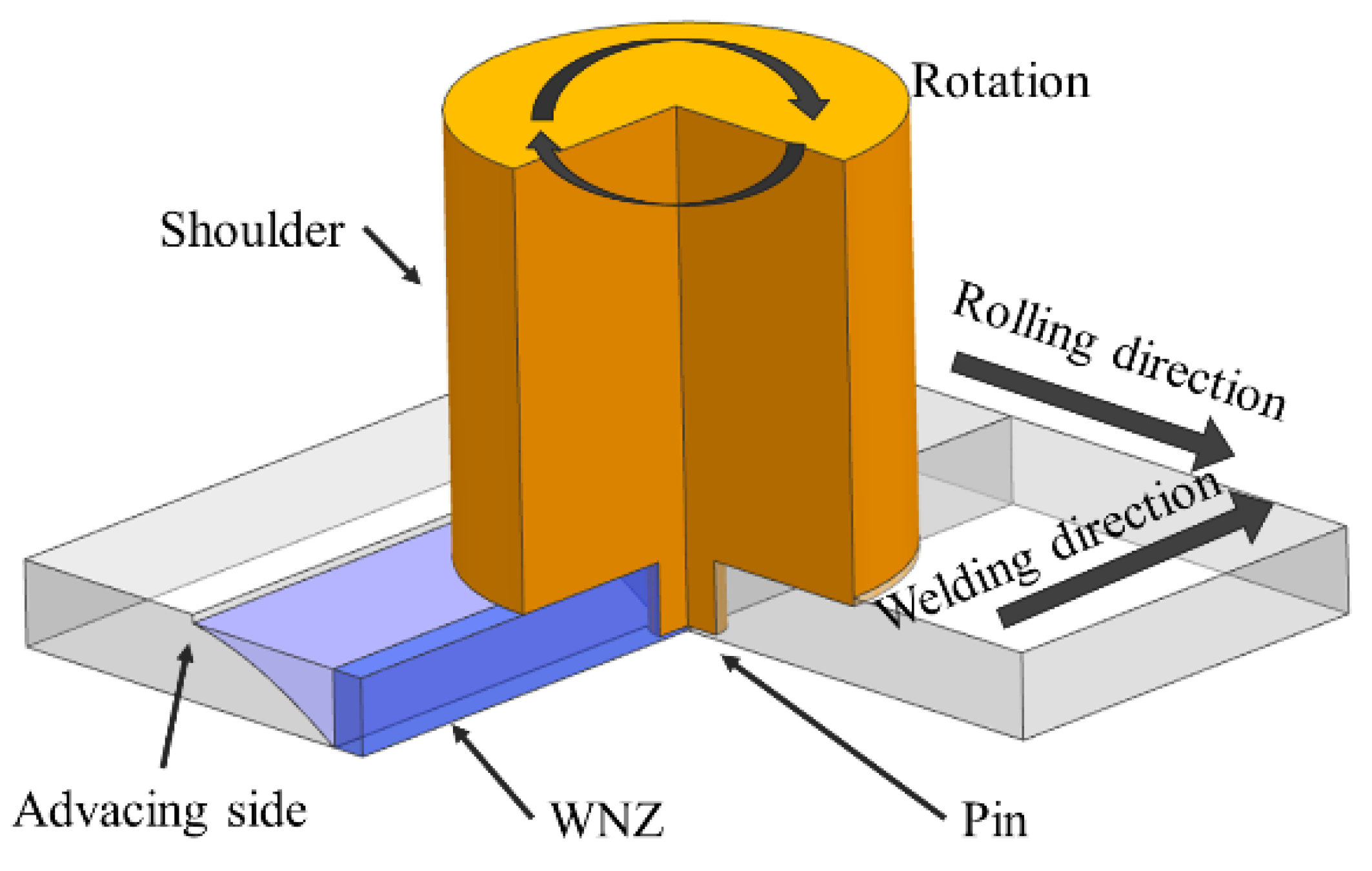
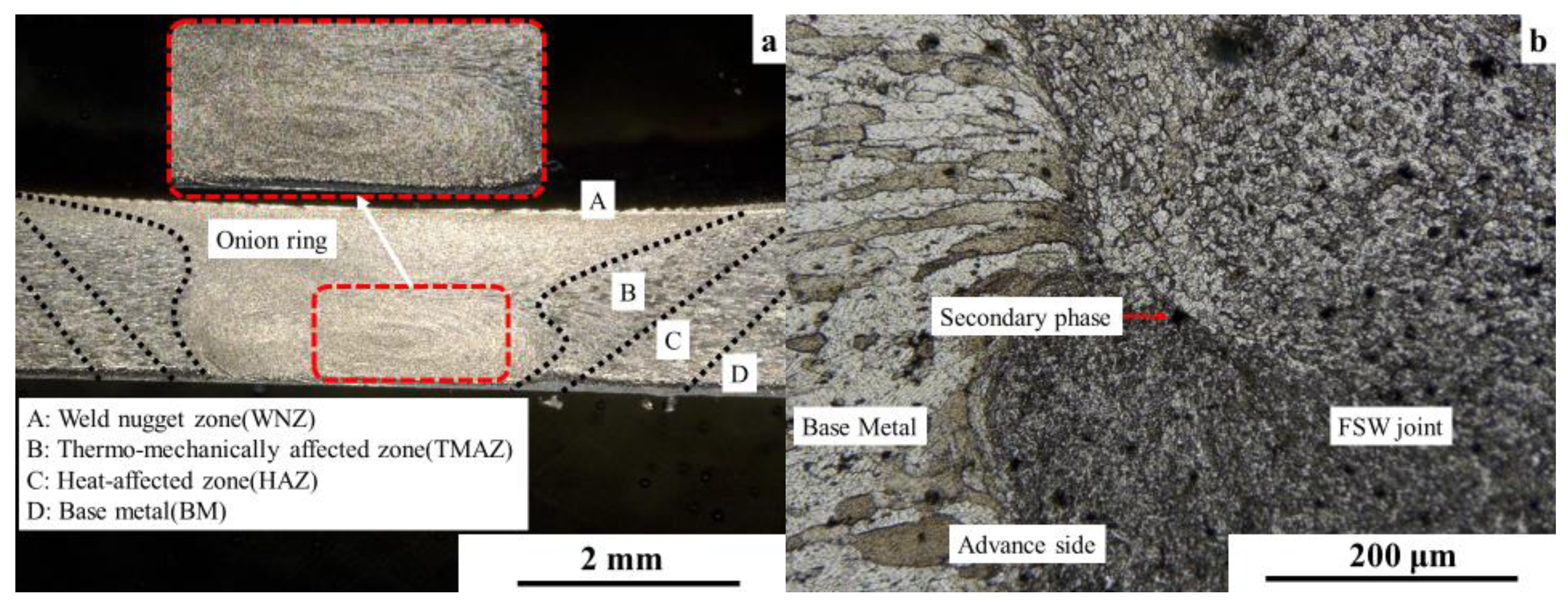
3.1.1. Microstructure of the Welding Joint

The cross-section structure of 2219 aluminum alloy FSW joint under the solution aging FSW technology is shown in Figure 4. According to Figure 4a, the cross-section of the 2219 aluminum alloy FSW joint is divided into four regions: the welding nugget zone (NZ), the thermo-mechanically affected zone (TMAZ), the heat-affect zone (HAZ), and the base metal. The NZ, which was directly affected by the pin and shoulder and experienced severe plastic flow during the FSW process, is the central region of the FSW joint with fine equiaxed grains. The TMAZ was affected by the plastic flow in NZ as well as the thermal cycle during the FSW process. The grains in TMAZ were stretched along the flow direction. The HAZ had a similar structure as the base metal but was slightly coarser as a result of the welding thermal cycle. The onion ring structure, which was formed as a result of the plastic flow during the FSW process [11], is also observed in Figure 4a. The advanced side of the weld joint is shown in Figure 4b. It can be seen that the density of secondary particles in NZ was higher than in other regions.

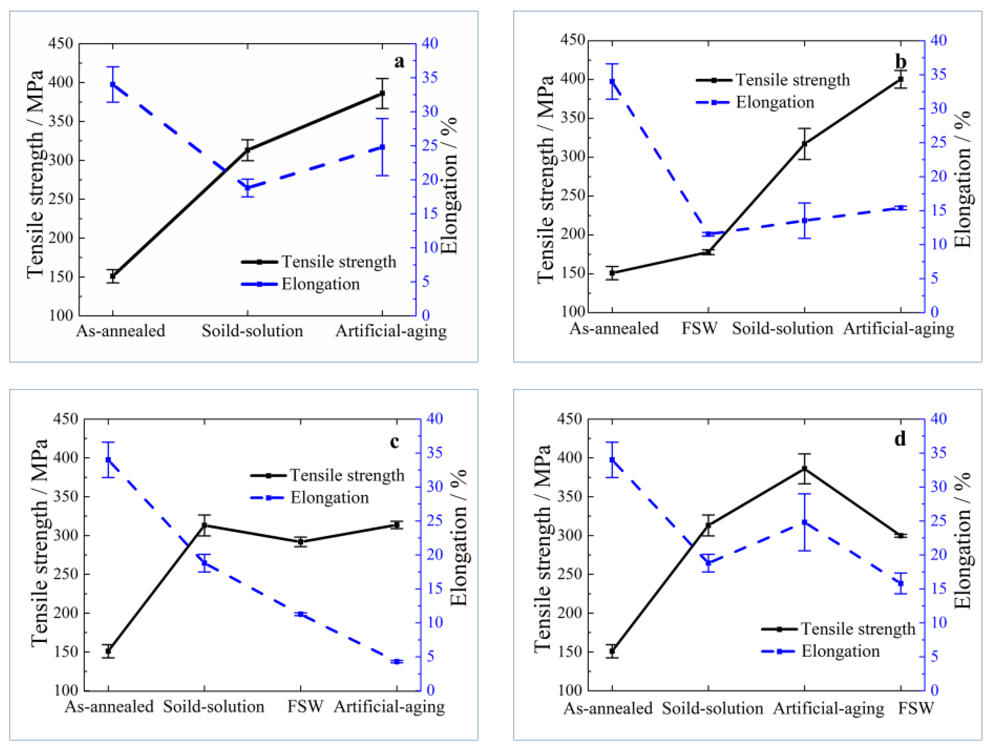
3.1.2. Mechanical Properties

The tensile test results of the 2219 aluminum alloy samples processed through solution aging (base metal), FSW solution aging, solution FSW aging, and solution aging FSW are shown in Figure 5.
On the basis of the tensile strength shown in Figure 5, the base metal samples and the FSW solution aging samples have higher strength compared with the other two compound technologies. According to previous studies, the strength of friction stir welded samples increased with a higher solution temperature [24]. This was attributed to the grain coarsening in the welding joint, which is caused by an imbalance between the thermodynamic driving forces and the pinning forces. The pining forces impeding the grain boundary migration decreased during solution. Moreover, because of the reprecipitation of precipitated phase, the tensile strength of welding joint increased after heat treatment [24]. The increase of strength after aging treatment of solution FSW aging samples was not as high as the base metal samples or the FSW solution aging samples. This can be attributed to the changes in the precipitation behavior of secondary phase caused by the FSW treatment, in particular, the accumulation of dislocation could improve the precipitating rate during aging treatment [16]. The localized deformation and thermal input in the welded region were harmful to the uniformity of the whole sample. As a result, the material of welding joint reached a peak aging state sooner than the base metal and was overaged; in contrast, the base metal reached peak aging condition. The strength of the samples after the solution aging FSW treatment were the lowest among three compound technologies. This can be attributed to the inhomogeneous microstructure of welding joint and the dissolving and coarsening of the precipitate phase caused by the FSW treatment [25]. Moreover, for the 2219-T6 aluminum alloy, a high rotation rate easily caused welding defects such as tunnel and void, which were clearly harmful to the mechanical properties [5].
On the basis of the elongation shown in Figure 5, the ductility of the samples under three compound technologies was obviously worse than the base metal. According to previous research [12], the density of the secondary phase was variable across the onion ring structure. In addition, the secondary phase could continually grow during aging treatment even the Cu element was no longer oversaturated [26]. The inhomogeneous structure and the coarsening of the secondary phase ere the predominant causes for the lower ductility of welded samples. For the FSW solution aging samples, the elongation increased with the heat treatment process, which indicates that the inhomogeneity in the welded samples could be modified during solution treatment. Meanwhile, the solution FSW aging samples exhibited the worst ductility amongst all samples. This is because of the welding defects and overaging effect both caused by FSW [5,16]. The elongation of the solution aging FSW samples was similar to the FSW solution aging samples; however, there was a significant difference in the tensile strength of the samples between these two technologies. This phenomenon indicated that the loss of strength due to the FSW process could be recovered by the solution aging treatment while the ductility remained reduced.
In conclusion, the thermal input and the accumulation of plastic deformation caused a deterioration in mechanical properties after the FSW treatment. There was a dramatic decrease in the ductility of the 2219 aluminum alloy under the co-effect of FSW and heat treatment as a result of the interaction between severe plastic deformation and aging [27]. Through a comparison of the tensile results which were processed under all the four technologies above, it was clear that the strength loss due to the FSW process could be largely recovered by the solution aging treatment, which was mainly attributable to the high temperature during solution treatment.

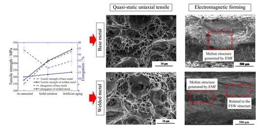
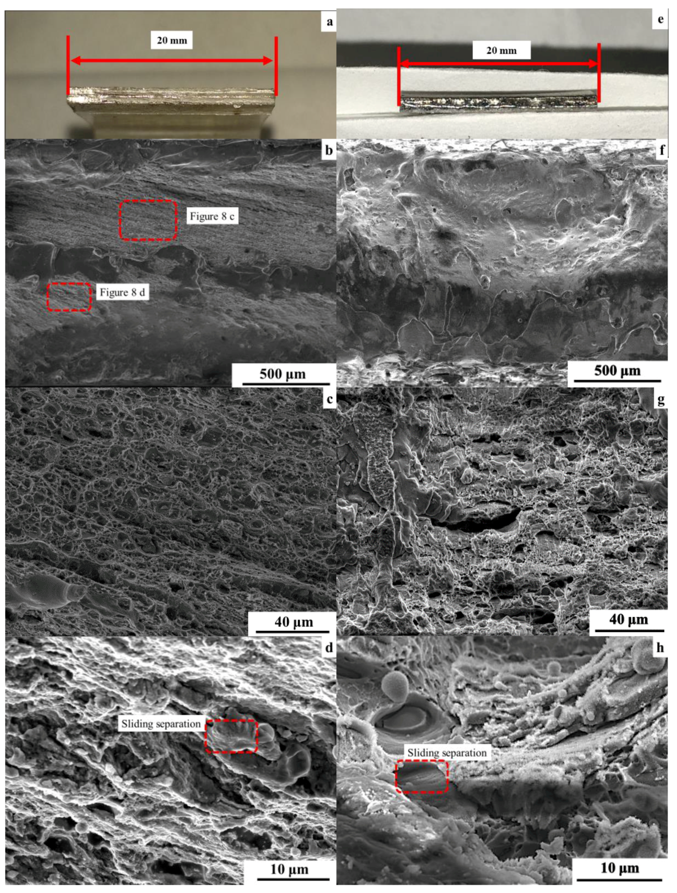
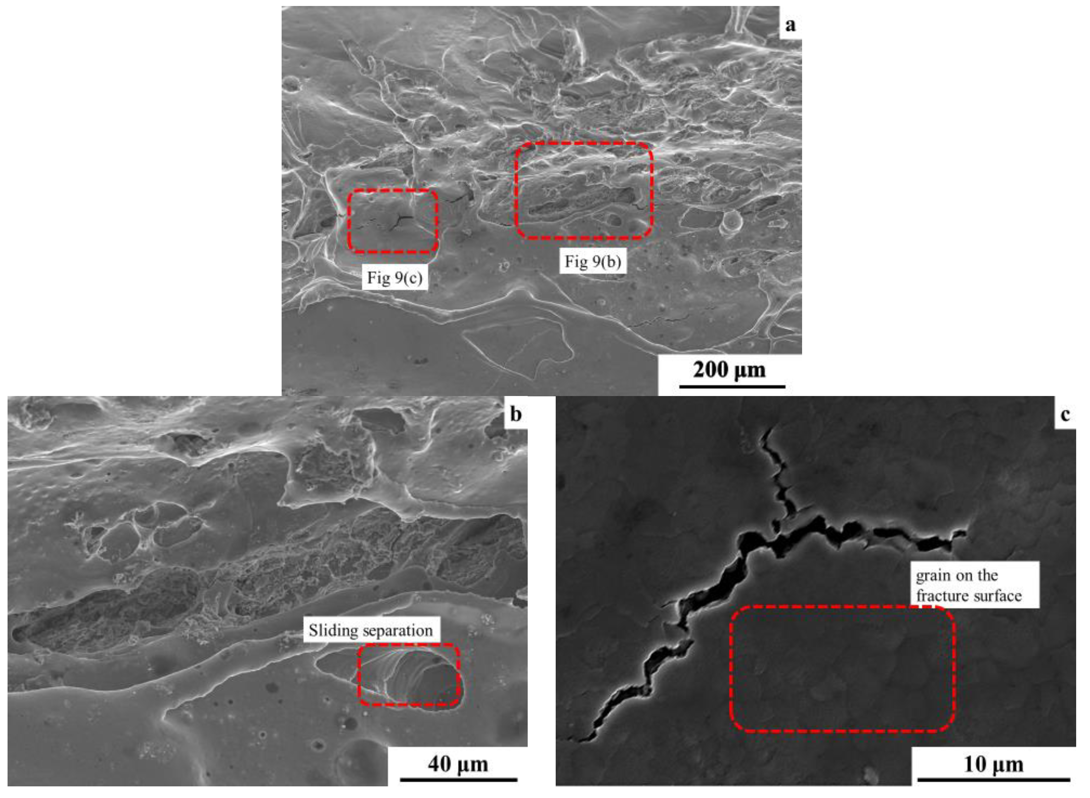
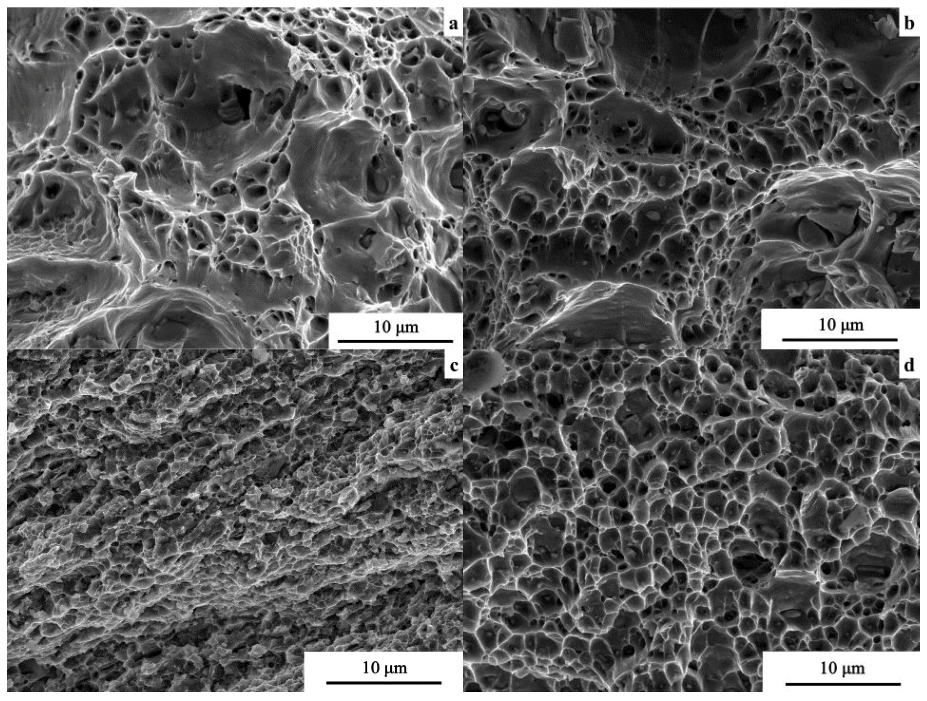
3.1.3. Fracture Appearance

The SEM observations of the fractures which were formed during the tensile test are shown in Figure 6. The fracture of the FSW solution aging sample shown in Figure 6b is a typical alloyed fracture appearance, which is a dispersive distribution of large-sized dimples surrounded by small-sized dimples. Secondary particles can be observed at the bottom of several dimples as well as sharp tearing ridge on the dimples. This is similar to the fracture appearance of the base metal shown in Figure 6a. The fracture of the solution FSW aging sample shown in Figure 6c has a quasi-dissociation fracture appearance. The dimples are shallow and small, with a reduced sharp tearing ridge, which indicates a poor ductility of the 2219 aluminum alloy. The fracture appearance of the solution aging FSW sample shown in Figure 6d has the morphology characteristics of both the FSW solution aging sample and solution FSW aging sample. The large-sized dimples found in Figure 6a,b cannot be found on the fracture surface of the solution aging FSW sample, which presents a more uniformly sized distribution of dimples. It has been established that the appearance of dimples is greatly affected by the secondary particles in the matrix [28]. Accordingly, the size distribution of the secondary phase became more uniform after the FSW process because of the fragmenting of large-sized particles caused by the severe plastic deformation. This distribution led to the formation of the fracture appearance shown in Figure 6d. For the fracture appearance of the solution FSW aging sample, the severe plastic deformation caused by FSW strongly suggested a precipitating rate during the aging processing. Thus, the aging treatment could significantly increase the negative effects of FSW on the mechanical properties, even causing the banded appearance on Figure 6c.

3.2. EMF Treatment

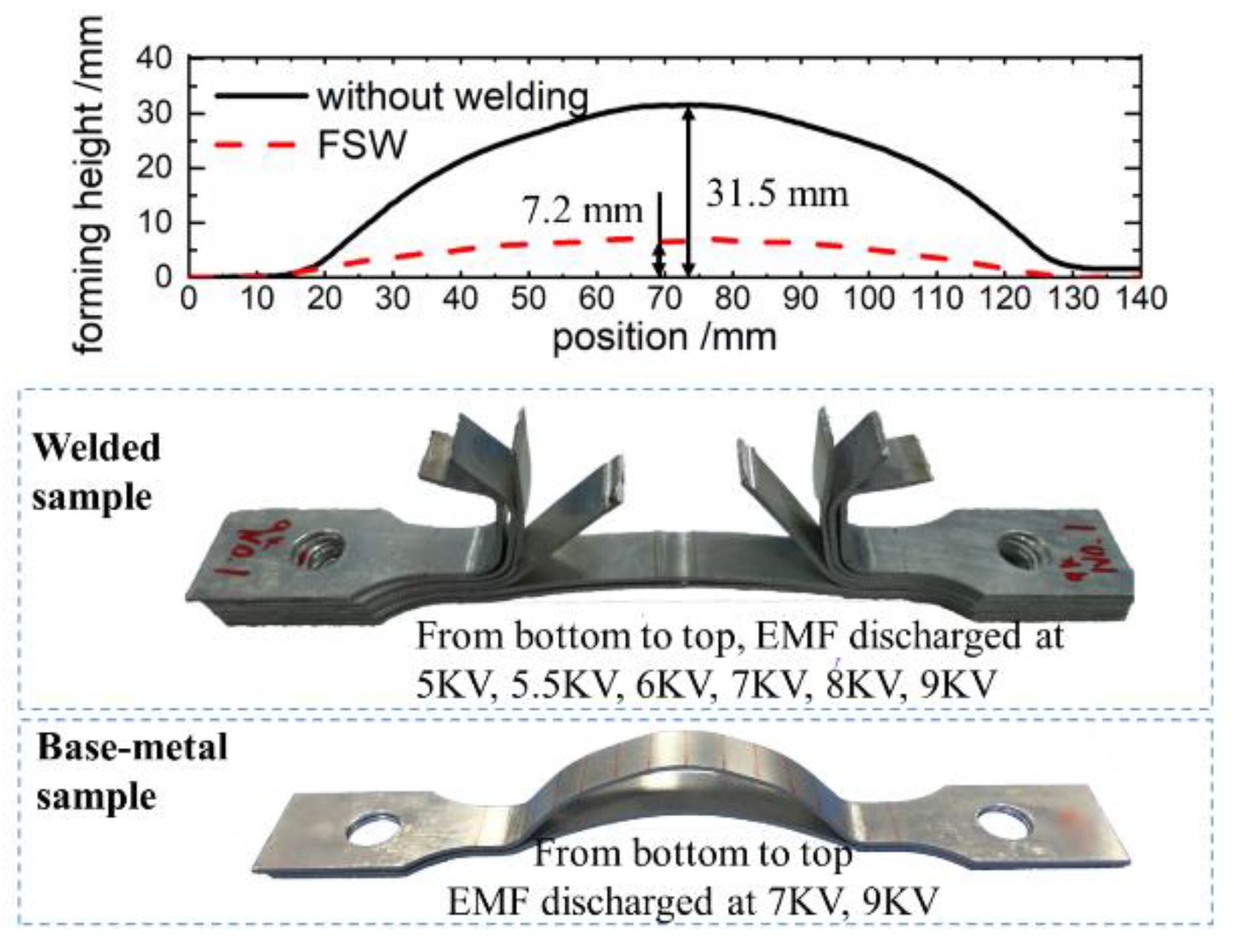
3.2.1. Forming Characteristics

The EMF treatment was performed on the samples under a solution aging treatment and a FSW solution aging treatment, which has demonstrated the optimal properties of all three compound technologies. The results shown in Figure 7 indicate that welded samples tended to fracture at lower discharging voltage compared with the base metal samples. The comparison of the forming height shows that the maximal strain of welded samples was significantly lower than the base metal samples. The fracture location on welded samples was approximately the middle of the welding joint where the NZ was located. Simultaneously, the fracture of the base-metal samples was located at the die corner where the stress concentration occurred.

3.2.2. Fracture Appearance

The fracture appearance of the welded sample and base metal sample is shown in Figure 8. Clearly, both contained bright silver regions on the fracture surface as shown in Figure 8a,e. Under further observation, which was performed by SEM and shown in Figure 8b,f, this structure was a large-scale surface with a molten appearance. Meanwhile, the fracture surface of the friction stir-welded samples had a layered structure which did not appear on the base metal sample. A banded texture was also found on the fracture surface of the welded sample, and further observations are shown in Figure 8c,d.
Observations of Figure 8c indicated an alternative distribution of dimples in different size. A texture on the holistic distribution of dimples also may have caused the banded texture on the fracture surface in Figure 8b, which can be attributed to the onion ring structure in the welding joint. The microstructure of welded material was variable across the onion ring structure. Notably, the density of the precipitated phase was different between the bright and dark layers in the onion structure shown in Figure 4a. The variation of microstructure led to a regular variation in the mechanical properties and caused the corresponding structure on the fracture surface.
The fracture surface shown in Figure 8d indicates a multi-fracture-type structure with few dimple structures, despite its similarity to the fracture appearance shown in Figure 8c in macro level. Brittle fracture appearances were also present such as intergranular fracture in addition to the ductile fracture structure-like dimples or sliding separation. The banded structure was predominantly caused by the plastic flow during the FSW process which was similar to the structure shown in Figure 8c. The multi-fracture-type structure can be attributed to two causes: the lack of the driving force from the welding shoulder, causing a relatively weak region of welding joint, and the heat from the Joule effect of induced current, causing a weakening of the grain boundaries.
Regarding the fracture structure of the base metal sample under the EMF process, a multi-fracture-type structure was also present, as shown in Figure 8g,h, but no banded structure appeared.
Further observations of the large-scale surface with a molten appearance are shown in Figure 9a. Pit structure-like dimples were present with a sliding separation structure on the side wall appearing on the large-scale surface as shown in Figure 9b. Meanwhile, a structure of crack was also found on the surface and observed in high magnification as shown in Figure 9c. It was easy to discern a pattern of grain boundaries as shown around the crack, the size of which was close to the size of the grains in the NZ, which was around 5–10 μm.
In conclusion, the EMF process was greatly affected by the FSW treatment:
FSW treatment causes a weakening in the properties of the welded material attributable to welding defects such as a segregation of the precipitated phase and the liquation cracking [29]. The Joule effect of induced eddy current during EMF also reduced the ductility of the 2219 aluminum alloy during the EMF process. The microstructure variation across the onion ring structure, which was formed during the FSW process, caused a variation of mechanical properties and led to the banded structure on the fracture surface of electromagnetic-formed samples. Because only the upper layer of 2219 aluminum alloy could be affected by the friction of the shoulder during the FSW process, a weak region in the bottom of welding joint as produced. With the addition of the skin effect of the induced eddy current during the EMF process, the fracture type varied in thickness within the sample.
In conclusion, regarding the formation of the large-scale surface, the welding defects and regional precipitated phase segregation caused an increase in electrical resistance and led to a higher temperature under the Joule effect during the EMF process. The strength of the welding joint was weakened under high temperature and an intergranular fracture was formed because of the weakened grain boundaries. When the samples fractured, a strong electric arc occurred which could be clearly seen during the EMF process. The surface of fracture was partially melted under the effect of the arc, and the melted appearance was formed.

4. Conclusions

  • The effects of high temperature during heat treatment caused a coarsening of grains and reprecipitation of precipitated phase in the welding join; it was able to recover the strength reduced during the FSW process, but ductility remained reduced after heat treatment. The performance of FSW after a solid-solution treatment on 2219 aluminum alloy caused an overaging effect during subsequent aging treatment and led to poor ductility.
  • The formability of welded samples under EMF was lower compared with base metal samples because of the poor mechanical properties. The onion ring structure formed during FSW treatment caused a variation in both the microstructure and properties of the 2219 aluminum alloy and led to the banded structure on the fracture surface. A multi-fracture-type structure was generated due to the interaction of plastic flow caused by FSW and induced eddy current caused by EMF.
  • During the EMF process, an intergranular fracture appearance was generated as a result of the Joule effect of the induced eddy current. The induced eddy current also caused the molten surface on the fracture through the electric arc when the fracture occurred. The melted surface covered the original fracture appearance and formed the bright silver appearance on the fracture surface of the 2219 aluminum alloy under EMF treatment.

Author Contributions

Zeyu Wang, Liang Huang, and Xiaoxia Li designed and performed the experiments; Zeyu Wang, Liang Huang, and Huijuan Ma analyzed and discussed the data; Jianjun Li, Hui Zhu, Fei Ma, and Junjian Cui provided guidance for this research; Zeyu Wang and Liang Huang wrote the paper;

Funding

This research was founded by [the National Natural Science Foundation of China] grant number [51575206] and [51435007], [the EU Marie Curie Actions-MatProFuture Project] grant number [FP7-PEOPLE-2012-IRSES-318968], [the Innovation Funds for Aerospace Science and Technology from China Aerospace Science and Technology Corporation] grant number [CASC150704], [the Open Funds from the State Key Laboratory of Advanced Design and Manufacturing for Vehicle Body] grant number [31615006], and [the Fundamental Research Funds for the Central University] grant number [2016YXZD055].

Acknowledgments

This work was supported by the National Natural Science Foundation of China (Grant No. 51575206 and 51435007), the EU Marie Curie Actions-MatProFuture Project (Grant No. FP7-PEOPLE-2012-IRSES-318968), the Innovation Funds for Aerospace Science and Technology from China Aerospace Science and Technology Corporation (Grant No. CASC150704), the Open Funds from the State Key Laboratory of Advanced Design and Manufacturing for Vehicle Body (Grant No. 31615006), and the Fundamental Research Funds for the Central University (Grant No. 2016YXZD055).

Conflicts of Interest

The authors declare no conflict of interest.

References

  1. Narayana, G.V.; Sharma, V.M.J.; Diwakar, V. Fracture behaviour of aluminium alloy 2219-T87 welded plates. Sci. Technol. Weld. Join. 2013, 9, 121–130. [Google Scholar] [CrossRef]
  2. Gupta, R.K.; Panda, R.; Mukhopadhyay, A.K. Study of Aluminum Alloy AA2219 after Heat Treatment. Met. Sci. Heat Treat. 2015, 57, 350–353. [Google Scholar] [CrossRef]
  3. Klett, A.; Hegels, J.; Bartesch, G. Spinforming of Friction Stir Welded AA2219 Circular Blanks for ARIANE 5 Main Stage Tank Bulkheads. DVS Ber. 2004, 229, 90–94. [Google Scholar]
  4. Regensburg, A.; Schürer, R.; Weigl, M. Influence of Pin Length and Electrochemical Platings on the Mechanical Strength and Macroscopic Defect Formation in Stationary Shoulder Friction Stir Welding of Aluminium to Copper. Metals 2018, 8, 85. [Google Scholar] [CrossRef]
  5. Zhang, Z.; Xiao, B.L.; Ma, Z.Y. Effect of welding parameters on microstructure and mechanical properties of friction stir welded 2219Al-T6 joints. J. Mater. Sci. 2012, 47, 4075–4086. [Google Scholar] [CrossRef]
  6. Son, S.K.; Takeda, M.; Mitome, M. Precipitation behavior of an Al-Cu alloy during isothermal aging at low temperatures. Mater. Lett. 2005, 59, 629–632. [Google Scholar] [CrossRef]
  7. Seth, M.; Vohnout, V.J.; Daehn, G.S. Formability of steel sheet in high velocity impact. J. Mater. Process. Technol. 2005, 168, 390–400. [Google Scholar] [CrossRef]
  8. Psyk, V.; Risch, D.; Kinsey, B.L. Electromagnetic forming—A review. J. Mater. Process. Technol. 2011, 211, 787–829. [Google Scholar] [CrossRef]
  9. Zhu, H.; Huang, L.; Li, J. Strengthening mechanism in laser-welded 2219 aluminium alloy under the cooperative effects of aging treatment and pulsed electromagnetic loadings. Mater. Sci. Eng. A 2018, 714, 124–139. [Google Scholar] [CrossRef]
  10. Mohammadi-pour, M.; Khodabandeh, A.; Mohammadi-pour, S. Microstructure and mechanical properties of joints welded by friction-stir welding in aluminum alloy 7075-T6 plates for aerospace application. Rare Metals 2016, 1–9. [Google Scholar] [CrossRef]
  11. Hamilton, C.; Dymek, S.; Blicharski, M. A model of material flow during friction stir welding. Mater. Charact. 2008, 59, 1206–1214. [Google Scholar] [CrossRef]
  12. Krishnan, K.N. On the formation of onion rings in friction stir welds. Mater. Sci. Eng. A 2002, 327, 246–251. [Google Scholar] [CrossRef]
  13. Chu, G.; Sun, L.; Lin, C. Effect of Local Post Weld Heat Treatment on Tensile Properties in Friction Stir Welded 2219-O Al Alloy. J. Mater. Eng. Perform. 2017, 26, 5425–5431. [Google Scholar] [CrossRef]
  14. Wang, S.C.; Starink, M.J. Precipitates and intermetallic phases in precipitation hardening Al-Cu-Mg-(Li) based alloys. Int. Mater. Rev. 2005, 50, 193–215. [Google Scholar] [CrossRef]
  15. An, L.; Cai, Y.; Liu, W. Effect of pre-deformation on microstructure and mechanical properties of 2219 aluminum alloy sheet by thermomechanical treatment. Trans. Nonferr. Met. Soc. China 2012, 22, s370–s375. [Google Scholar] [CrossRef]
  16. Ning, A.; Liu, Z.; Zeng, S. Effect of large cold deformation after solution treatment on precipitation characteristic and deformation strengthening of 2024 and 7A04 aluminum alloys. Trans. Nonferr. Met. Soc. China 2006, 16, 1341–1347. [Google Scholar] [CrossRef]
  17. Owolabi, G.M.; Bolling, D.T.; Odeshi, A.G. The Effects of Specimen Geometry on the Plastic Deformation of AA 2219-T8 Aluminum Alloy Under Dynamic Impact Loading. J. Mater. Eng. Perform. 2017, 26, 5837–5846. [Google Scholar] [CrossRef]
  18. Olasumboye, A.; Owolabi, G.; Odeshi, A. Dynamic Response and Microstructure Evolution of AA2219-T4 and AA2219-T6 Aluminum Alloys. J. Dyn. Behav. Mater. 2018, 1–17. [Google Scholar] [CrossRef]
  19. Tan, J.; Zhan, M.; Liu, S. Guideline for Forming Stiffened Panels by Using the Electromagnetic Forces. Metals 2016, 6, 267. [Google Scholar] [CrossRef]
  20. Liu, Z.; Fan, T.; Hu, H. Possible Mechanism of Plasticity Influenced by Magnetic Field. Chin. Phys. Lett. 2006, 23, 175–177. [Google Scholar]
  21. Ruszkiewicz, B.J.; Grimm, T.; Ragai, I. A Review of Electrically-Assisted Manufacturing with Emphasis on Modeling and Understanding of the Electroplastic Effect. J. Manuf. Sci. Eng. 2017, 139, 110801. [Google Scholar] [CrossRef]
  22. Kaltenboeck, G.; Demetriou, M.D.; Roberts, S. Shaping metallic glasses by electromagnetic pulsing. Nat. Commun. 2016, 7, 10576. [Google Scholar] [CrossRef] [PubMed]
  23. Ringer, S.P.; Hono, K. Microstructural Evolution and Age Hardening in Aluminium Alloys: Atom Probe Field-Ion Microscopy and Transmission Electron Microscopy Studies. Mater. Charact. 2000, 44, 101–131. [Google Scholar] [CrossRef]
  24. Feng, J.C.; Chen, Y.C.; Liu, H.J. Effects of post-weld heat treatment on microstructure and mechanical properties of friction stir welded joints of 2219-O aluminium alloy. Mater. Sci. Technol. 2006, 22, 86–90. [Google Scholar] [CrossRef]
  25. Chen, Y.C.; Feng, J.C.; Liu, H.J. Precipitate evolution in friction stir welding of 2219-T6 aluminum alloys. Mater. Charact. 2009, 60, 476–481. [Google Scholar] [CrossRef]
  26. Gang, L.; Jun, S. A Model for Age Strengthening of plate-like-precipitate-containing Al Alloys. Chin. J. Nonferr. Met. 2001, 11, 337–347. (In Chinese) [Google Scholar]
  27. Ning, A.; Liu, Z.; Zeng, S. Effect of large cold deformation on characteristics of age-strengthening of 2024 aluminum alloys. Trans. Nonferr. Met. Soc. China 2006, 16, 1121–1128. [Google Scholar] [CrossRef]
  28. Mittra, J.; Banerjee, S.; Tewari, R. Fracture behavior of Alloy 625 with different precipitate microstructures. Mater. Sci. Eng. A 2013, 574, 86–93. [Google Scholar] [CrossRef]
  29. Huang, C.; Kou, S. Partially Melted Zone in Aluminum Welds—Liquation Mechanism and Directional Solidification. Weld. J. 2000, 79, 113. [Google Scholar]
Figure 1. Schematic illustration of FSW process.
Metals 08 00305 g001
Figure 2. Schematic illustration of electromagnetic forming (EMF) process.
Metals 08 00305 g002
Figure 3. Schematic illustration of the processing route.
Metals 08 00305 g003
Figure 4. Schematic of FSW joint: (a) full view (b) partial enlarged view of advancing side.
Metals 08 00305 g004
Figure 5. Comparison of quasi-static uniaxial tension result between base metal sample and as-welded sample: (a) base metal (b) FSW solution aging (c) solution FSW aging (d) solution aging FSW.
Metals 08 00305 g005
Figure 6. Schematic of fracture of 2219 aluminum alloy under different compound technology: (a) base metal (b) FSW solution aging (c) solution FSW aging (d) solution aging FSW.
Metals 08 00305 g006
Figure 7. Comparison of EMF between base metal sample and as-welded sample.
Metals 08 00305 g007
Figure 8. Fracture appearance of EMF samples: (ad) as-welded sample (eh) base metal sample.
Metals 08 00305 g008
Figure 9. Appearance of flat fracture surface.
Metals 08 00305 g009
Table 1. Chemical composition of 2219 aluminum alloy (mass fraction %).
AlCuMnTiZrV
bal.6.20.30.0580.150.08

