2. Experimental Procedures
Fe-32Mn-7Cr-1Mo-0.3N austenite steel was used in this work. Before the experiment, the test steel was treated with solid solution at 1100 °C for 90 min and then quenched in water to ensure the single austenitic phase in base metal (BM). The plates for FSW were cut to thickness gauge of 3 mm by using wire-electrode cutting. The thermal physical simulated specimens were cut to cylinders with a length and diameter of 12 and 8 mm, respectively, from the BM by using wire-electrode cutting.
A tungsten-rhenium alloy FSW tool, which consisted of a concave shoulder with 16 mm diameter and an unthreaded pin with 3 mm length, was used during the welding process, and the tilting angle of the tool was 2°. A constant rotation speed of 600 rpm and welding speed of 80 mm/min were used under a protective atmosphere of flowing Ar gas. To determine the effect of FSW on the microstructure in the HAZ, the thermal data from this zone were collected using the OMB-DAQ-2416 data acquisition system. The thermocouples were welded in the plates at 10 mm away from the seam center to capture thermal histories. After FSW, PWHT was performed on the as-welded joints by holding at 1100 °C for 90 min and then quenching in water.
The thermal cycle simulation tests were performed on a Gleeble 3500 thermo-mechanical simulator (Dynamic Systems Inc., Austin, TX, USA) at peak temperatures of 450 °C, 550 °C, and 650 °C. Before the tests, the simulated specimens were stuck in the compression anvils. The pressing force is 60 kgf. During the tests, the heating and cooling rates of all specimens were consistent with the actual thermal cycle of the HAZ. It is worth mentioning that there were two load modes of the compression anvils: (1) no additional load mode: during the whole welding thermal cycle simulation, “force” was selected as the mode of compression anvils, and the pressing force was kept at 60 kgf; and (2) with additional load mode: during the heating stage of the welding thermal cycle simulation, “stroke” was selected as the mode of compression anvils, and the displacement was kept at 0 mm. That is to say, the positions of compression anvils were unchanged. Then, during the cooling stage of the simulation process, “force” was selected as the mode of compression anvils, and the pressing force was changed to 60 kgf. After the thermal cycle simulation tests, the heat treatment process, which was the same as the PWHT, was performed on the simulated specimens.
The microstructures of the FSW joints and simulated specimens were observed by optical microscopy (OM) (Carl Zeiss Jena, Oberkochen, Germany) and orientation imaging microscopy (OIM) (HITACHI, Tokyo, Japan). The Vickers hardness profiles of the joints before and after PWHT were measured in the cross-section perpendicular to the welding direction by using of FM-ARS9000 (FUTURE-TECH, Tokyo, Japan).
3. Experimental Results
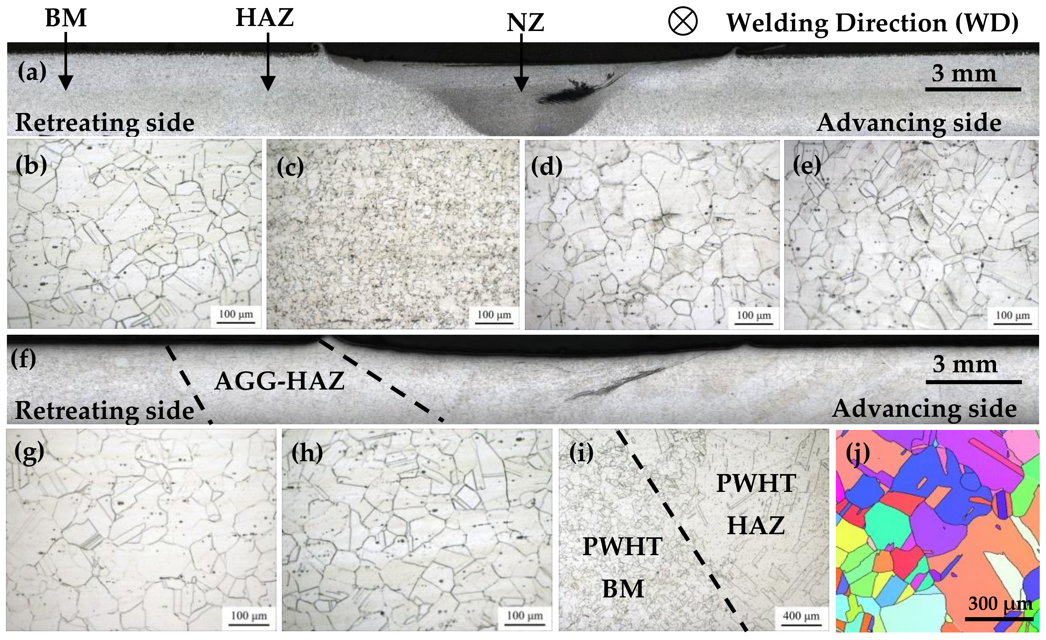
The transverse cross-section microstructures of the as-welded FSW joint of Fe-32Mn-7Cr-1Mo-0.3N steel without internal defects are presented in
Figure 1a. Three typical zones, namely, BM, HAZ, and NZ, are labeled. The BM microstructure in the as-welded joint is shown in
Figure 1b, which is mainly composed of grains with an average size of 52 μm and several annealing twins.
Figure 1c shows that the NZ grains are significantly refined to an average size of approximately 16 μm, which can be attributed to the dynamic recrystallization [
3,
16]. No obvious TMAZ with dynamic recovery is found in the FSW joint. The HAZ microstructure in the as-welded joint is shown in
Figure 1d,e, which is similar to the features of the BM. In addition, there are some slip bands in the grains of the HAZ, which are typical deformation features. As is well known, in FSW, the HAZ is the zone in which no tool-promoted plastic deformation occurs. This zone should be mainly affected by the welding thermal cycle. However, unlike conventional fusion welding, rigid fixation for welded plates is necessary in the FSW process. Therefore, the plates are not the free ends in the direction perpendicular to the welding. In the condition of rigid binding of the plates, the material in the HAZ is subjected to the pressure stress caused by the thermal expansion during the FSW process. Given the relatively low temperature, the dynamical recrystallization and dynamical recovery cannot occur in the HAZ. As a result, the cold deformation characteristics such as the slip bands were preserved.
The joint overview after PWHT is shown in
Figure 1f, and the detailed observations of the regions selected from the joint are shown in
Figure 1g–j. The microstructure of the PWHT BM is stable with initial grain size. In comparison, the NZ grains have grown significantly with an average size of approximately 48 μm, which is roughly close to that of the initial BM. Notably, the AGG phenomenon is observed in the HAZ of the PWHT joint. The grains in the AGG regions have clearly grown to an average size of approximately 320 μm as shown in
Figure 1i,j. Moreover, the width of these regions are estimated to be approximately 12 mm in each side of the joint, which is wider than the regions characterized by slip bands in the as-welded joint (as labeled by the dotted lines in
Figure 1f).
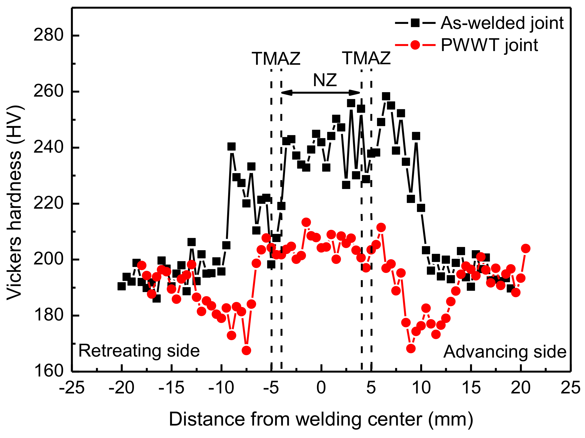
The hardness distributions along the weld cross-section centerline of the as-welded and PWHT joints are shown in
Figure 2. In the as-welded joint, the hardness of the NZ is approximately 250 HV, which is much higher than that of the BM (190 HV). In addition, the hardness of HAZ also increases obviously, which should be related to the plastic deformation that occurred in the HAZ. After PWHT, the hardness of the NZ decreases and almost reaches the BM level, which is due to the grain growth in this zone. Besides that, due to the AGG during PWHT in the HAZ, two softened zones appear in the FSW joint. In addition, the width of the softened zones in the PWHT joint is wider than the hardened regions in the as-welded joint.
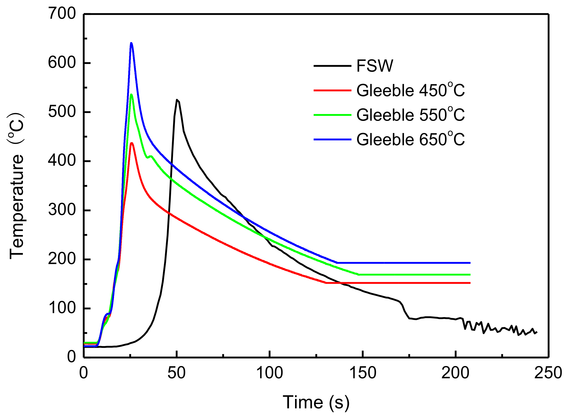
According to the above analysis, the AGG in the HAZ may be related to the welding thermal cycle and the compressive stress caused by the thermal expansion. To reveal the causes of the AGG in the HAZ, thermal physical simulations with various axial stresses were employed. The black curve in
Figure 3 shows the welding thermal cycle experienced by the temperature measuring point set on the HAZ. The other three curves represent simulated thermal cycles at three different peak temperatures according to the same heating and cooling rate of the actual thermal cycle.
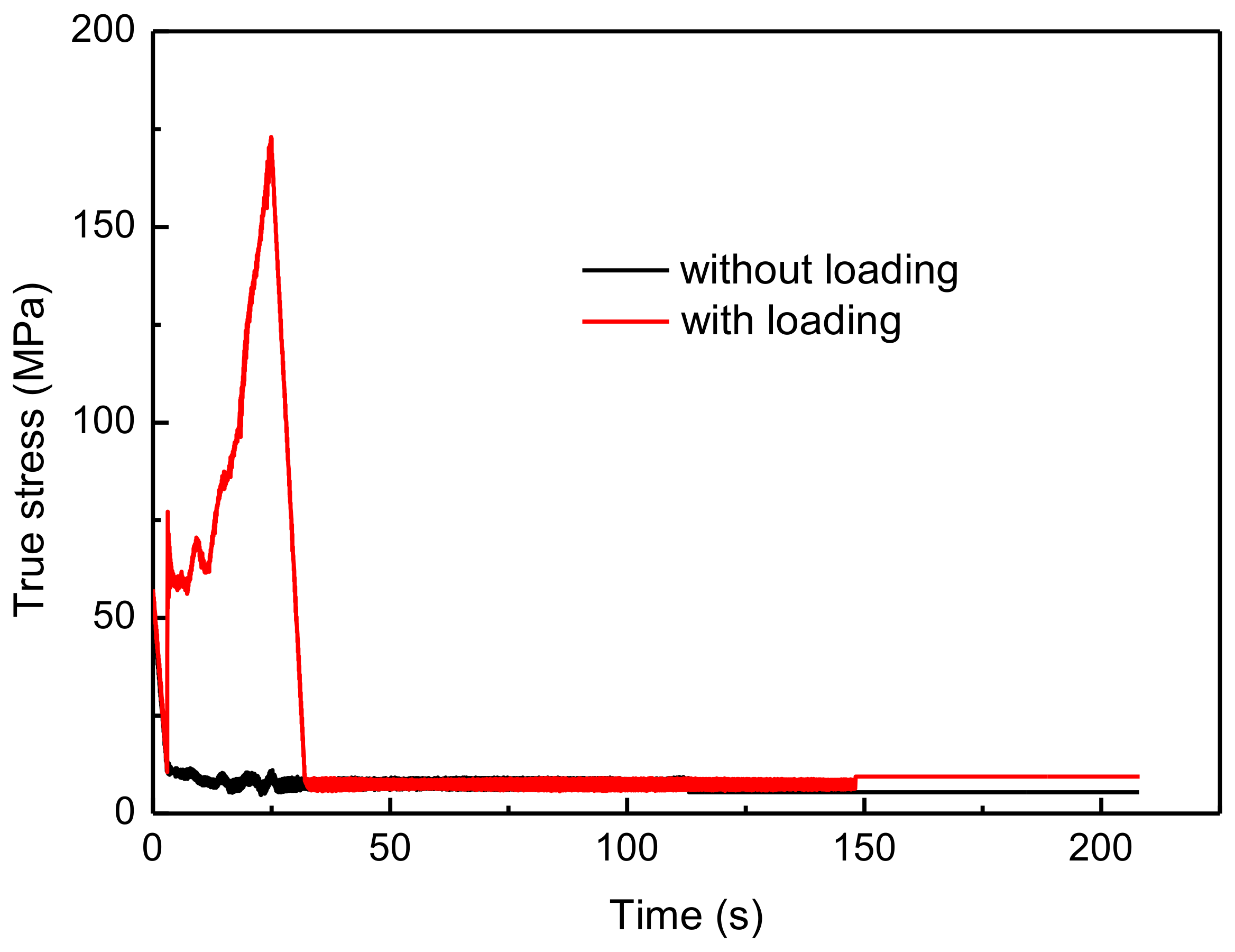
Figure 4 shows the variation of the axial stresses of the thermal cycle simulated specimen with time under two load modes. The stress of the thermal simulated specimen without additional load is almost unchanged, which is always approximately 10 MPa. In this condition, the specimen is only affected by the thermal cycle. However, during the heating stage of the thermal simulated specimen with additional load, “stroke” was selected as the control mode of compression anvils with a constant displacement of 0 mm. The specimen expands due to the increase in temperature. However, the fixation of the compression anvils’ position actually limits the expansion of the thermal simulated specimen. It is equivalent to a compressive load for the specimen. Therefore, as shown in
Figure 4, with the increase in temperature, the stress of the specimen with additional load increases significantly. It reaches approximately 175 MPa. In this condition, the specimen is affected by the effects of the thermal cycle and additional load.
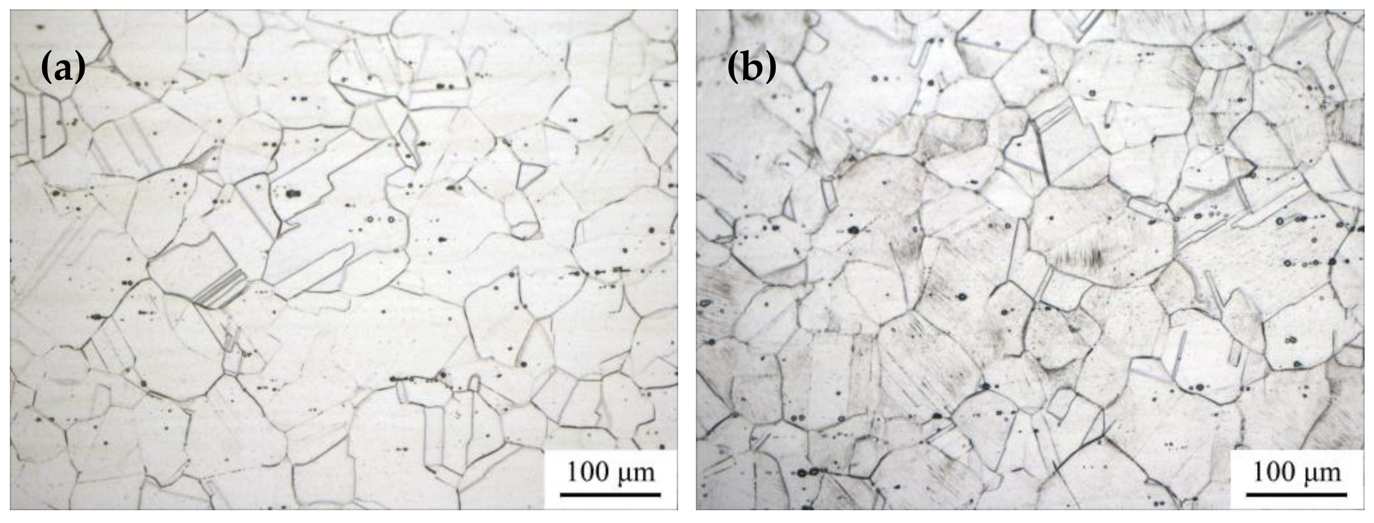
Figure 5 shows the microstructures of the thermal simulated specimens in the two load conditions when the peak temperature is 550 °C. A comparison of
Figure 1 and
Figure 5 shows that the microstructure of the simulated specimen without additional load is similar to that of the BM in the as-welded FSW joint. The average grain size is approximately 55 μm, and there is no slip band in the grains. However, the microstructure of the simulated specimen with additional load is similar to that of the HAZ in actual as-weld FSW joint. Moreover, a small number of slip bands can be observed in the grains. This finding indicates that, during the thermal cycle simulated test process, plastic deformation occurred in this specimen due to the effect of the compression anvils.
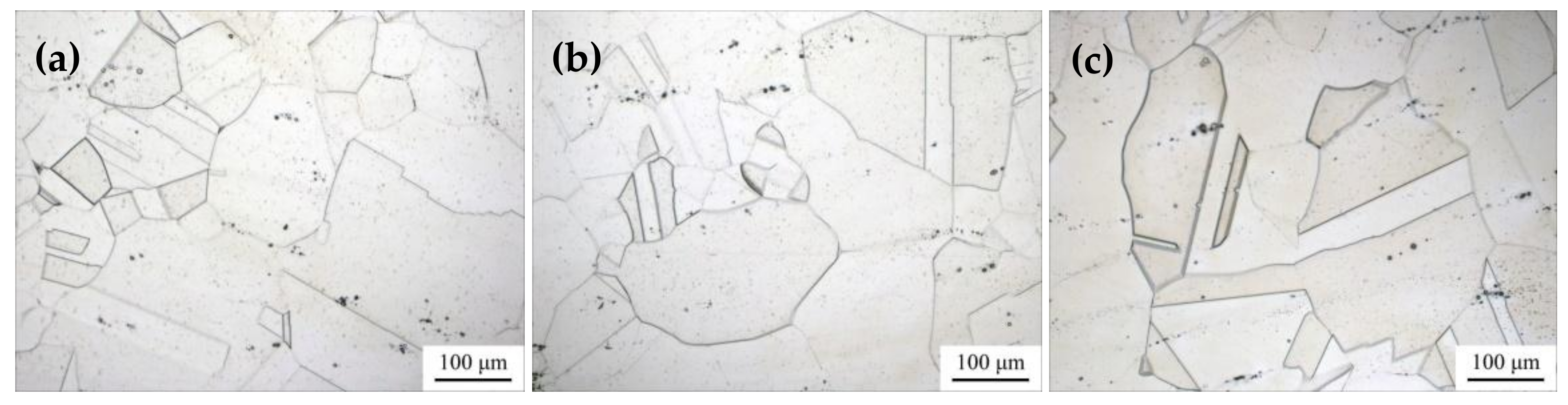
Figure 6 shows the microstructure of the thermal simulated specimens without additional load after heat treatment. First of all, by comparing
Figure 5 and
Figure 6, the grains of the thermal simulated specimens at three different peak temperatures all grow abnormally after heat treatment. This finding indicates that the microstructural stability of the present steel can be weakened only due to the welding thermal cycle. In addition, it causes AGG in the subsequent heat treatment process. The additional load is not a necessary factor for AGG. Second, the grain size of the three thermal simulated specimens after heat treatment is basically the same, which indicates that the peak temperature of the thermal cycle has a limited influence on the degree of AGG in a temperature range.
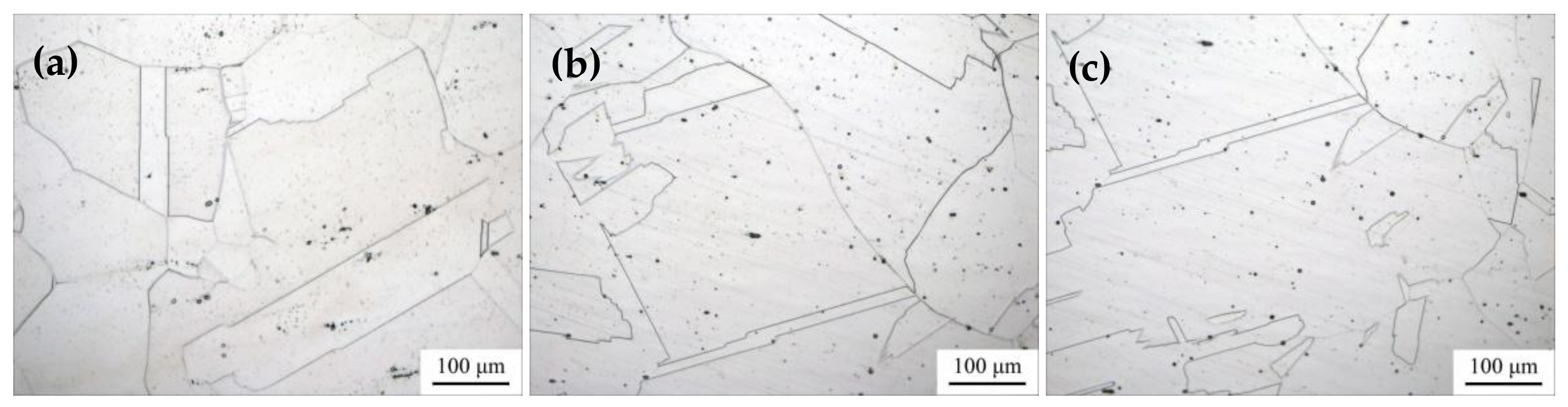
Figure 7 shows the microstructure of the thermal simulated specimens with additional load after heat treatment. First of all, it is similar to the thermal simulated specimens without additional load. After heat treatment, AGG also occurred in all specimens at three different peak temperatures. Second, compared with the thermal simulated specimens without additional load (by comparing
Figure 6 and
Figure 7), the grains in the specimens with slight strain are much coarser after subsequent heat treatment. Therefore, this finding proves that, although the additional load is not a necessary factor to induce AGG, it can promote the degree of grain growth in PWHT.
4. Discussion
Different from the aged-strengthening Al alloy, there are no second phase particles and other precipitates in the present steel. Moreover, due to the heat treatment before welding, the steel consists of single austenite. Therefore, the AGG in the HAZ of the FSW joint during PWHT can hardly be explained by the dissolution of the second phase particles. In addition, unlike the FSW joint of Al alloy, the AGG was not found in the NZ and TMAZ but the HAZ of the PWHT joint for the present steel. Therefore, the AGG that occurred in the HAZ of the PWHT joint was also not related to the non-uniform grain size distribution. From the previous analysis, the local strain that occurred in the HAZ will promote AGG after heat treatment, but the effect of local strain on the AGG of the HAZ should be discussed. The microstructural stability in terms of the mobility of grain boundaries may account for it.
A study [
17] pointed out that, besides the pinning forces due to the second phase particles, the solute atoms in the material will also exert a drag effect on the migration of the grain boundaries. The migration of the grain boundaries will become more difficult if the solute atoms are segregated at the grain boundaries. On the contrary, once the segregation of these atoms disappears or is reduced, the grain boundaries will migrate more easily in the same thermal activation condition, which leads to grain growth.
Generally, the segregation of the solute atoms can be divided into equilibrium segregation and non-equilibrium segregation (NES) [
18]. The equilibrium segregation of the solute atoms is a thermal activation process controlled by the solid temperature. Based on the peak temperature of weld thermal cycle shown in
Figure 3, it can be confirmed that the equilibrium segregation is not the primary mechanism.
The NES of the solute atoms is a kinetic process and has been wildly accepted in terms of the diffusion of atom-vacant couple induced by the following factors: (1) quenching, (2) radiation, (3) low stress, and (4) recrystallization [
17,
18,
19,
20]. The NES of solute atoms at grain boundaries arising from quenching effects was first reported by Aust [
21] and Anthony [
22,
23]. The formation of the solute atom-vacancy complex in the matrix is considered to play a major role in the process. When a sample is maintained at a solution treatment temperature for a period of time and then cooled to a certain low temperature, the equilibrium vacancy concentration will be reduced. Consequently, a loss of vacancies will appear along the grain boundaries as they act as a sink of vacancy. The decrease of vacancy concentration causes the dissolution of the complexes into vacancies and solute atoms, which reduces the concentration of complexes near the grain boundaries. Meanwhile, in the regions far away from the grain boundaries, where no other vacancy traps are present, vacancies will recombine with solute atoms to form new complexes, which also reduces the vacancy concentration and increases the complex concentration. This leads to the increase in complex concentration in the regions remote from the grain boundaries. Therefore, a concentration gradient appears between the grain boundaries and the regions beyond it. This gradient drives the complexes to diffuse from the regions far from the grain boundaries to the grain boundaries. It causes the excessive solute atoms to concentrate in the grain boundaries and results in the NES. After segregating at grain boundaries, the solute atoms tend to diffuse into grains due to the concentration gradient between the grain boundary and the inner grain. Thus, the NES of the solute atoms will disappear in the conditions of sufficient annealing and long-term service.
The NES of solute atoms at grain boundaries induced by recrystallization effects was reported by Jahaz [
17]. The Cottrell atmosphere and recrystallization phenomena are considered to play a major role in this process. According to the theory of Cottrell atmosphere, the solute atoms tend to gather to the dislocations. Once recrystallization occurs, new grain boundaries move towards high-dislocation-density regions and leave low dislocation densities behind them. Moreover, the existing models for NES consider that the grain boundaries are infinite sinks for vacancies and dislocations. Therefore, with the recrystallization process, the solute atoms have been left at the grain boundaries, resulting in the NES.
In addition, the stress also affects the NES of the solute atoms. Xu [
18] pointed out that the grain boundaries emit vacancies when a compression stress is exerted on them and absorb vacancies when a tension stress is exerted. The tensile stress will further promote the NES of the solute atoms at the grain boundaries. On the contrary, the pressure stress will lead to the non-equilibrium dilution of the solute atoms at the grain boundaries.
For high manganese steel and high nitrogen steel, the NES of different solute atoms during quenching process had been previously reported [
24,
25]. Combined with the above discussions, it can be deduced that the transformation of the NES state of the solute atoms at the grain boundaries leads to the AGG in the HAZ of the joint for the present steel during the whole FSW process and the subsequent heat treatment.
In the heat treatment before welding, the NES of solute atoms at the grain boundaries will occur in the whole plate during the process of water quenching. During the subsequent FSW process, the BM area is not affected by the mechanical and thermal effects of the welding. Moreover, it keeps the NES state of solute atoms at grain boundaries. However, due to the effect of the welding thermal cycle, the NES state of the solute atoms disappears in the HAZ. In the NZ, although the welding thermal cycle will lead to the disappearance of the NES state of solute atoms at the grain boundaries, the recrystallization induces the NES of the solute atoms at the grain boundaries in the NZ again due to the dynamic recrystallization that occurred in the NZ. Therefore, after the FSW, the NES state of solute atoms at grain boundaries exists in the BM and NZ of the as-welded joint. However, the NES state in the HAZ has disappeared. In the HAZ, the drag effect of the solute atoms disappears and thus leads to a significant enhancement in the mobility of the grain boundaries.
During the FSW process, due to the grain refinement in the NZ, the interface energy stored in this zone is relatively high. Therefore, the grains here have the driving force for growth. However, the drag effect of the solute atoms leads to the poor mobility of the grain boundaries. Hence, only normal grain growth has occurred in the NZ during the PWHT. The microstructure of the BM has been in a relatively stable state because of the heat treatment before welding. In addition, the mobility of grain boundaries is poor due to the drag effect of the solute atoms here. Thus, there is no obvious grain growth in the BM of the FSW joint during the PWHT either. After the FSW process, the mobility of grain boundaries is enhanced due to the disappearance of the NES of the solute atoms in the HAZ. As a result, the migration of those grain boundaries becomes easier than in other zones in the joint and thus arouses the AGG during the PWHT. As mentioned in the previous section, due to the rigid restraint produced by the fixture, the HAZ is subjected to pressure stress caused by the thermal expansion during the FSW process. This stress state further aggravates the de-segregation of solute atoms in the HAZ. It further promotes the AGG during PWHT (as simulated in
Figure 6 and
Figure 7).
