Dissolution of Scrap in Hot Metal under Linz–Donawitz (LD) Steelmaking Conditions

 ,
,
Abstract
1. Introduction
2. Background of Diffusive Scrap Melting
3. Description of the Experiment
4. Discussion of the Experimental Results
5. Discussion
Author Contributions
Funding
Acknowledgments
Conflicts of Interest
References
- Turkdogan, E.T. Fundamentals of Steelmaking; The Institute of Materials: London, UK, 1996; pp. 209–244. [Google Scholar]
- Ghosh, A.; Chatterjee, A. Ironmaking and Steelmaking Theory and Practice; PHI Learning Private Limited: Delhi, India, 2015; pp. 285–292. [Google Scholar]
- Asai, S.; Muchi, I. Effect of scrap melting on the process variables in LD converter caused by the change of operating conditions. Trans. ISIJ 1971, 11, 107–115. [Google Scholar]
- Gaye, H.; Wanin, M.; Gugliermina, P.; Schittly, P. Kinetics of scrap dissolution in the converter. Theoretical model and plant experimentation. In Proceedings of the 68th Steelmaking Conference, AIME, Detroit, MI, USA, 14–17 April 1985; pp. 91–103. [Google Scholar]
- Isobe, K.; Maede, H.; Ozawa, K.; Umezawa, K.; Saito, C. Analysis of the scrap melting rate in high carbon molten iron. ISIJ 1990, 76, 2033–2040. [Google Scholar]
- Zhang, L.; Oeters, F. Schmelzen und Mischen von Legierungsstoffen in Stahlschmelzen; Verlag Stahleisen GmbH: Düsseldorf, Germany, 2012; pp. 38–40. [Google Scholar]
- Szekely, J.; Chuang, Y.K.; Hlinka, J.W. The melting and dissolution of low-carbon steels in iron-carbon melts. Metall. Trans. 1972, 3, 2825–2833. [Google Scholar] [CrossRef]
- Shukla, A.K.; Deo, B.; Robertson, D.G.C. Scrap Dissolution in Molten Iron Containing Carbon for the Case of Coupled Heat and Mass Transfer Control. Metall. Mater. Trans. B 2013, 44, 1407–1427. [Google Scholar] [CrossRef]
- Den Hartog, H.W.; Kreyger, P.J.; Snoeijer, A.B. Dynamic model of the dissolution of scrap in BOF process. CRM Rep. 1973, 37, 13–22. [Google Scholar]
- Kawakami, M.; Takatani, K.; Brabie, L.C. Heat and Mass Transfer Analysis of Scrap Melting in Steel Bath. Tetsu-to-Hagané 1999, 85, 658–665. [Google Scholar] [CrossRef]
- Kruskopf, A.; Holappa, L. Scrap melting model for steel converter founded on interfacial solid/liquid phenomena. Metall. Res. Technol. 2018, 115, 201–208. [Google Scholar] [CrossRef]
- Sethi, G.; Shukla, A.K.; Das, P.C.; Chandra, P.; Deo, B. Theoretical Aspects of Scrap Dissolution in Oxygen Steelmaking Converters. In Proceedings of the AISTech 2004 Proceedings Volume II, Nashville, TN, USA, 15–17 September 2014; pp. 915–926. [Google Scholar]
- Medzhibozhskiy, M.Y. Basis of Thermodynamic and Kinetic of Steelmaking; Vischa shkola: Kyiv, Ukraine, 1979; p. 229. [Google Scholar]
- Lytvynyuk, Y.; Schenk, J.; Hiebler, M.; Sormann, A. Thermodynamic and Kinetic Model of the Converter Steelmaking Process. Part 1: The Description of the BOF Model. Steel Res. Int. 2014, 85, 537–543. [Google Scholar] [CrossRef]
- Penz, F.M.; Bundschuh, P.; Schenk, J.; Panhofer, H.; Pastucha, K.; Paul, A. Effect of Scrap Composition on the Thermodynamics of Kinetic Modelling of BOF Converter. In Proceedings of the 2nd VDEh-ISIJ-JK Symposium, Stockholm, Sweden, 12–13 June 2017; pp. 124–135. [Google Scholar]
- Zarl, M. Development and Evaluation of a BOF Pre-Processor Model. Master’s Thesis, Montanuniversität Leoben, Leoben, Austria, 2017. [Google Scholar]
- Esser, A.; Grossmann, S. Analytic expression for Taylor-Couette stability boundary. Phys. Fluids 1996, 8, 1814–1819. [Google Scholar] [CrossRef]
- Racina, A. Vermischung in Taylor-Couette Strömung; Universitätsverlag: Karlsruhe, Germany, 2009; pp. 29–40. [Google Scholar]
- Penz, F.M.; Schenk, J.; Ammer, R.; Maunz, B.; Pastucha, K. Dissolution behavior of ULC steel in carbon saturated hot metal. In Proceedings of the 2nd International Congress on Science and Technology of Steelmaking, Venice/Mestre, Italy, 12–13 June 2018. CD-ROM. [Google Scholar]
- Miettinen, J. Calculation of solidification-related thermophysical properties for steels. Metall. Mater. Trans. B 2018, 28 B, 281–297. [Google Scholar] [CrossRef]
- Chapra, S.C.; Canale, R.P. Métodos Numéricos para Engenharia, 4th ed.; McGraw-Hill International do Brasil Ltda: São Paulo, Brazil, 2008; p. 549. [Google Scholar]


| Definition | Hot metal | Scrap |
|---|---|---|
| Carbon content [wt%] | 4.58 | 0.1 |
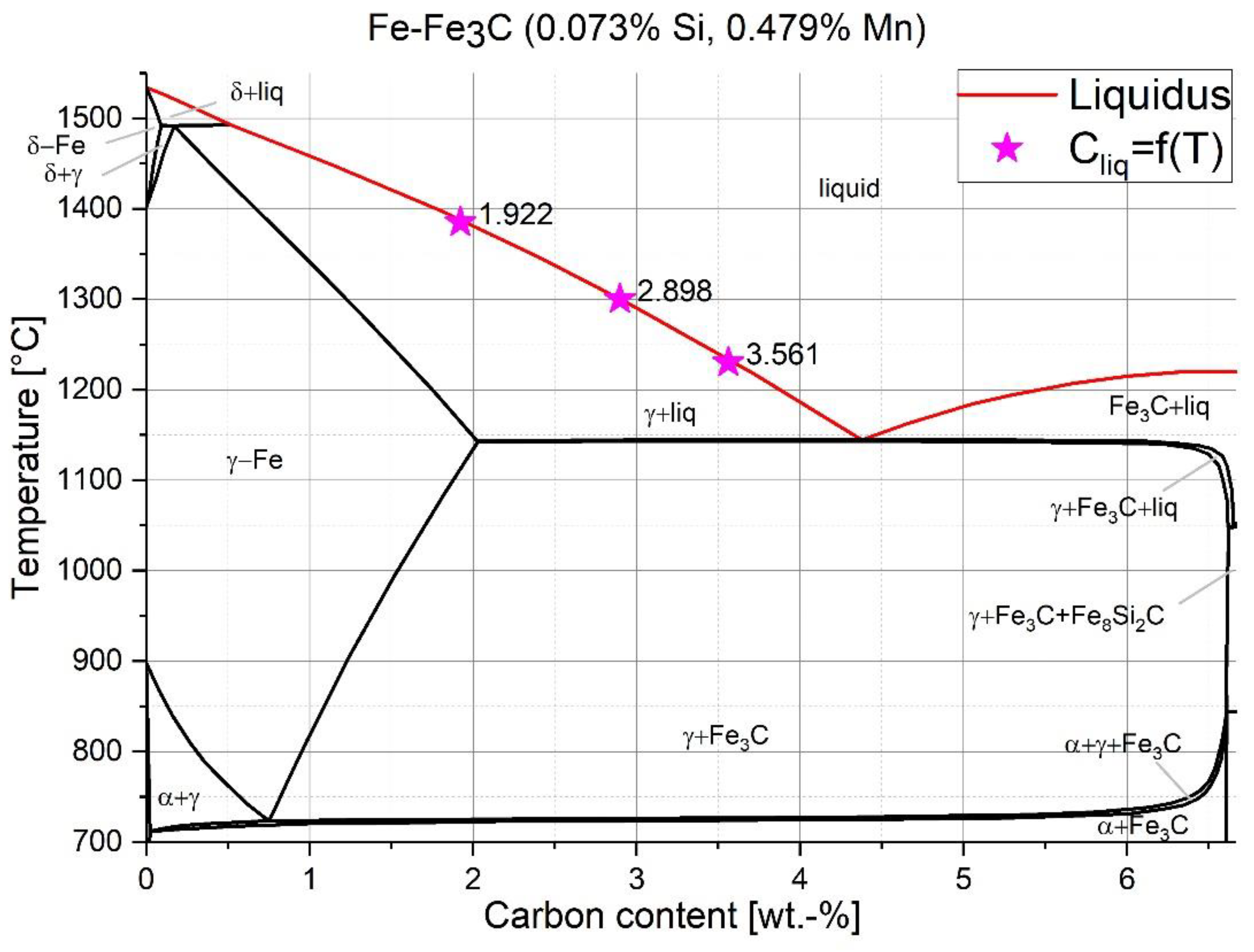
| Silicon content [wt%] | 0.37 | 0.0733 |
| Manganese content [wt%] | 0.63 | 0.479 |
| Phosphorus content [wt%] | 0.07 | 0.01 |
| Mass [g] | 330 | 26.3 |
| Initial temperature [°C] | 1305/1370/1450 | 25 |
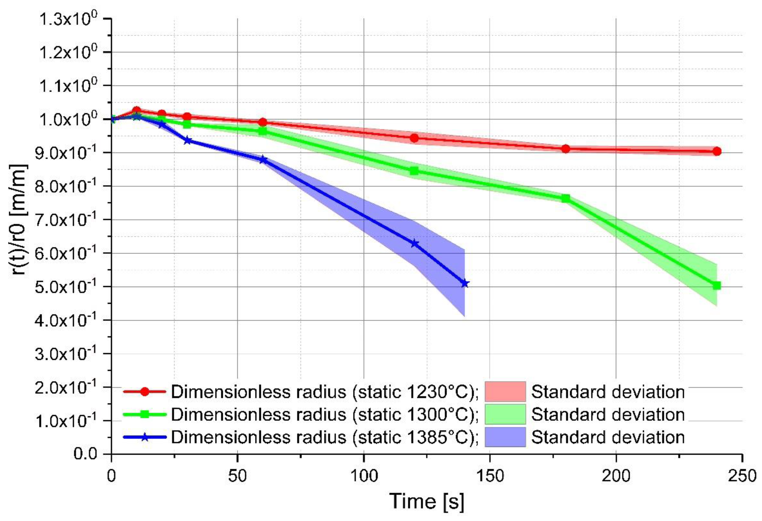
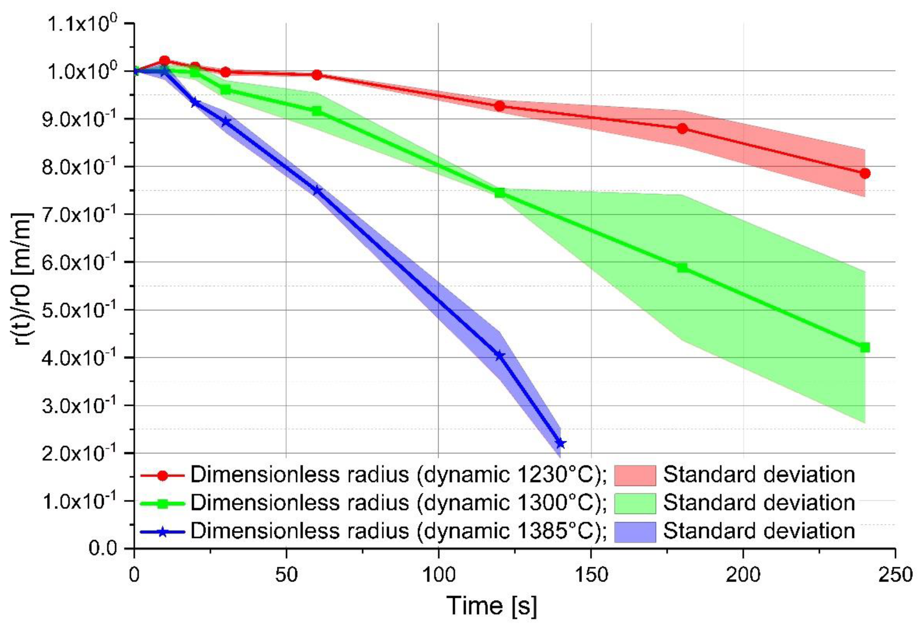
| Equilibrium temperature [°C] | 1230/1300/1385 | 1230/1300/1385 |
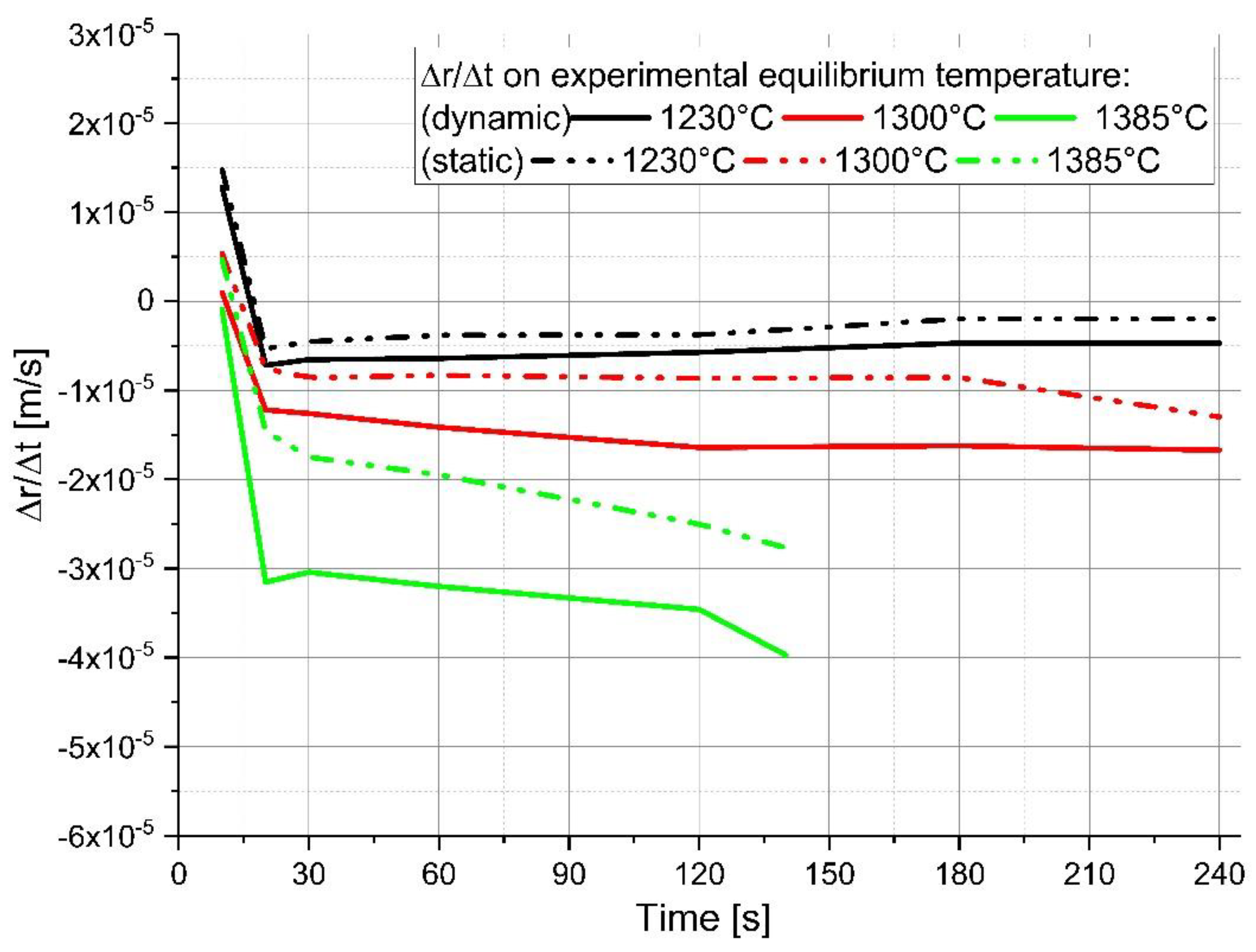
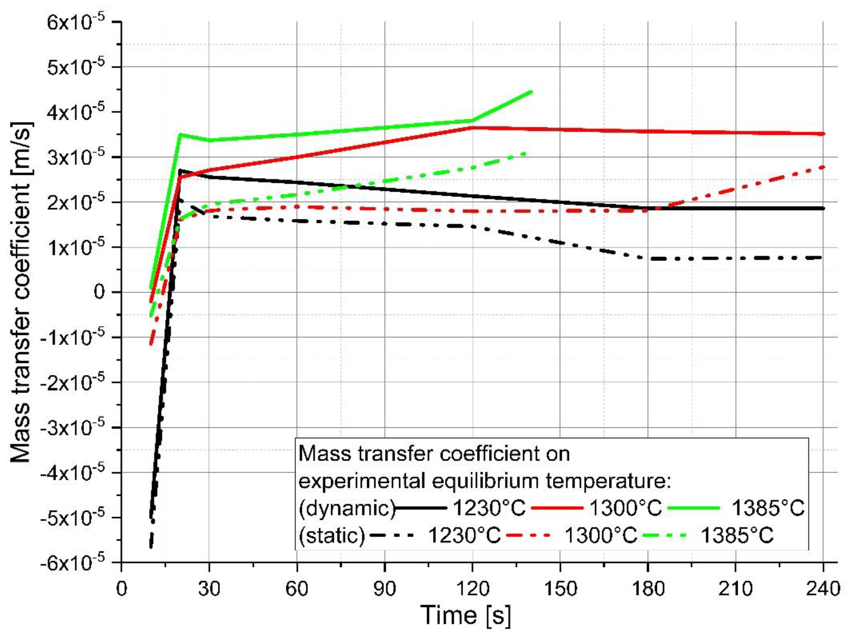
| Equilibrium temperature [°C] | 1230 | 1230 | 1300 | 1300 | 1385 | 1385 |
| Experimental condition | static | dynamic | static | dynamic | static | dynamic |
| Ablation rate [(m/s) × 10−6] | −1.98 to −5.30 | −4.68 to −7.19 | −7.5 to −12.9 | −12.1 to −16.7 | −14.6 to −27.7 | −30.4 to −39.7 |
| Mass transfer coefficient [(m/s) × 10−6] | 7.39–20.4 | 18.5–27.0 | 16.1–26.8 | 25.5–36.5 | 18.2–31.1 | 33.7–44.4 |
© 2018 by the authors. Licensee MDPI, Basel, Switzerland. This article is an open access article distributed under the terms and conditions of the Creative Commons Attribution (CC BY) license (http://creativecommons.org/licenses/by/4.0/).
Share and Cite
Penz, F.M.; Schenk, J.; Ammer, R.; Klösch, G.; Pastucha, K. Dissolution of Scrap in Hot Metal under Linz–Donawitz (LD) Steelmaking Conditions. Metals 2018, 8, 1078. https://doi.org/10.3390/met8121078
Penz FM, Schenk J, Ammer R, Klösch G, Pastucha K. Dissolution of Scrap in Hot Metal under Linz–Donawitz (LD) Steelmaking Conditions. Metals. 2018; 8(12):1078. https://doi.org/10.3390/met8121078
Chicago/Turabian StylePenz, Florian Markus, Johannes Schenk, Rainer Ammer, Gerald Klösch, and Krzysztof Pastucha. 2018. "Dissolution of Scrap in Hot Metal under Linz–Donawitz (LD) Steelmaking Conditions" Metals 8, no. 12: 1078. https://doi.org/10.3390/met8121078
APA StylePenz, F. M., Schenk, J., Ammer, R., Klösch, G., & Pastucha, K. (2018). Dissolution of Scrap in Hot Metal under Linz–Donawitz (LD) Steelmaking Conditions. Metals, 8(12), 1078. https://doi.org/10.3390/met8121078